Article

A Study on the Structure and Properties of NiCr-DLC Films Prepared by Filtered Cathodic Vacuum Arc Deposition

Key Laboratory of Beam Technology of Ministry of Education, School of Physics and Astronomy, Beijing Normal University, Beijing 100875, China
*
Authors to whom correspondence should be addressed.
Coatings 2025, 15(10), 1136; https://doi.org/10.3390/coatings15101136
Submission received: 28 August 2025 / Revised: 9 September 2025 / Accepted: 17 September 2025 / Published: 1 October 2025
(This article belongs to the Section Thin Films)

Abstract

Diamond-like carbon (DLC) films are valued for their high hardness and wear resistance, but their application in harsh environments is limited by high internal stress and poor corrosion resistance. Co-doping with transition metals offers a promising route to overcome these drawbacks by tailoring microstructure and enhancing multifunctional performance. However, the synergistic effects of Ni and Cr co-doping in DLC remain underexplored. In this study, Ni and Cr co-doped DLC (NiCr-DLC) films were fabricated using filtered cathodic vacuum arc deposition (FCVAD). By varying the C2H2 flow rate, the carbon content and microstructure evolved from columnar to fine-grained and compact structures. The optimized film (F55) achieved an ultralow surface roughness (Sa = 0.26 nm), even smoother than the Si substrate. The Ni–Cr co-doping promoted a nanocomposite structure, yielding a maximum hardness of 15.56 GPa and excellent wear resistance (wear rate: 4.45 × 10⁻⁷ mm3/N·m). Electrochemical tests revealed significantly improved corrosion resistance compared to AISI 304L stainless steel, with F55 exhibiting the highest corrosion potential, the lowest current density, and the largest impedance modulus. This work demonstrates that Ni-Cr co-doping effectively enhances the mechanical and corrosion properties of DLC films while improving surface quality, providing a viable strategy for developing robust, multifunctional protective coatings for demanding applications in aerospace, automotive, and biomedical systems.

1. Introduction

Diamond-like carbon (DLC) coating as an effective protective film has been extensively studied recently, due to the excellent properties such as low friction coefficient, high wear resistance, and better chemical inertness [1,2]. The film is mainly amorphous carbon consisting of a network of sp3 and sp2-bonded carbon atoms. Without a transition layer or element doping, the DLC film is very easy to spall from most metal substrates because of the high intrinsic compressive stress [3]. Metal-doped DLC films have been substantially studied recently due to their enhanced toughness, thermal stability, excellent tribological properties, as well as relatively lower residual stresses than those of pure DLC films [4,5,6,7,8,9,10].
Typically, the hetero-elements available for doping can be divided into two categories: one includes carbide-forming elements such as Ti [11,12,13,14,15], Cr [16,17,18], Mo [19], etc. When these metals are incorporated into DLC films, they form stable ionic bonds with carbon atoms and exist in the form of metal carbide nanoparticles within the carbon network. Yongqing Shen et al. [20] fabricated a series of Ti-DLC films using filtered cathodic vacuum arc deposition by tuning the C2H2 flow rate, achieving excellent tribological performance with a minimum coefficient of friction of 0.017 and a lowest wear rate of 5.91 × 10⁻⁸ mm3/N·m C.W. Zou et al. [21] prepared Cr-doped diamond-like carbon (Cr-DLC) films using a combination of medium-frequency magnetron sputtering and ion beam deposition. Their results indicated that Cr-DLC films with low Cr content contain Cr-C nanocrystallites. This structure not only enhances the mechanical properties of the film but also improves its tribological characteristics, allowing it to maintain excellent wear resistance even at an environmental temperature of 400°C.
For metals with nonaffinity for carbon, such as Cu [22], Al [23], and Ni [24]. When non-carbide-forming elements are incorporated into DLC films, strong chemical bonds are difficult to form between the metal and carbon atoms. This results in a certain degree of interfacial sliding ability at the boundaries between metal nanograins and the carbon matrix, effectively reducing the intrinsic stress of the film [2,25,26,27]. Suman Sahay et al. [2] fabricated Ni-C nanocomposite films via electrodeposition and found that the friction coefficient of the films with a DLC structure significantly decreased with increasing Ni content. Among them, the Ni-C composite film with the highest Ni content exhibited the maximum hardness of 7.6 GPa, whereas the pure amorphous DLC film showed the lowest hardness of 2.19 GPa. Han Zhou et al. [28] fabricated Ni/DLC nanocomposite films using filtered cathodic vacuum arc deposition (FCVAD) on unheated silicon (100) substrates by varying the flow rates of CH4 and C2H2. The films exhibited maximum hardness values of 13.2 GPa and 21.64 GPa at CH4 and C2H2 flow rates of 30 sccm and 40 sccm, respectively.
Filtered cathodic vacuum arc (FCVA) deposition is an advanced ion beam-based thin film growth technique developed in recent years. The incorporation of a magnetic filter effectively removes macroparticles and neutral species from the plasma, enabling the generation of a highly pure and dense plasma flux with densities up to 1026 m−3. This high plasma density significantly enhances the deposition rate. The resulting films exhibit smooth and uniform surfaces, with dense and continuous microstructures, leading to outstanding physical and chemical properties. S. N. Chen et al. [29] successfully fabricated AlCrNiTiV high-entropy alloy amorphous films (HEAAFs) using a novel co-filtered cathodic vacuum arc deposition (Co-FCVAD) technique. The resulting films exhibit a high hardness of 12.54 ± 0.65 GPa, surpassing that of most previously reported high-entropy alloy (HEA) films, along with excellent corrosion resistance in 5% H2SO4 solution, as evidenced by a low corrosion current density (Icorr) on the order of 10−7 A·cm−2. Yongqing Shen et al. [30] fabricated patterned diamond-like carbon (DLC) coatings on Si (100) substrates using filtered cathodic vacuum arc (FCVA) deposition. The results demonstrate that a 1 mm2 patterned structure, delimited by 100-μm-wide grooves, effectively enhances the tribological performance. Under dry and oil-lubricated conditions, the friction coefficients of the patterned coatings were measured to be 0.123 and 0.067, respectively, representing reductions of 10% and 21% compared to continuous DLC coatings of the same thickness.
In recent years, Ni-based alloys with high Cr content have gained significant attention as corrosion-resistant coating materials due to their exceptional resistance against oxidation, sulfidation, and hot corrosion. When the Cr content surpasses a critical threshold, a continuous, dense, and strongly adherent Cr2O3 oxide layer forms on the surface, effectively shielding the underlying alloy from environmental degradation. Additionally, Cr readily participates in forming carbide hard phases, which substantially enhances the matrix alloy’s mechanical strength. By optimizing the Cr/C ratio, Ni-Cr-C alloys can be designed to simultaneously achieve outstanding corrosion resistance and wear resistance. Building on this foundation, Ni-Cr-C co-doped diamond-like carbon (DLC) films have emerged as a promising material system. While DLC films co-doped with binary heteroatoms (such as Ti-Al-C [31], Ti-Ag-C [32]) have attracted increasing research interest, studies specifically focusing on the Ni-Cr-C system remain scarce. Particularly, the synergistic effects of Ni and Cr co-doping on the microstructure and multifunctional performance of DLC films—especially those deposited via filtered cathodic vacuum arc deposition (FCVAD)—are still poorly understood. This work addresses this knowledge gap by systematically investigating the influence of C2H2 flow rate on the microstructure and properties of NiCr-DLC films. Given that excessive doping promotes increased metal carbide formation, which degrades tribological performance, precise control over the structure, distribution, and morphology of nanocrystalline carbides and metal clusters is critical for optimizing the film’s functional properties.

2. Materials and Methods

In this study, the films were deposited on austenitic stainless steel (AISI 304L) and (100)-oriented single-crystal silicon substrates using FCVAD. The stainless steel specimens (20 mm × 20 mm × 5 mm) were ultrasonically cleaned in anhydrous ethanol, acetone, and deionized water for 15 min each to remove surface contaminants prior to deposition. A circular Ni-Cr alloy target (atomic ratio 4:1) served as the cathodic vacuum arc source, and the Ni-Cr plasma was guided into the deposition chamber through a 90° magnetic filtering duct, effectively eliminating neutral species and macro-particles. Before deposition, the substrates were subjected to 60 s of sputter cleaning under bias voltages of −800, −600 and −400 V, respectively. During deposition, a Ni-Cr metallic interlayer (~100 nm thick) was first deposited for 10 min, followed by co-deposition of the Ni-Cr-DLC layer through the introduction of C2H2 gas for 50 min. The substrate bias was initially set to −200 V, while maintaining a NiCr target arc current of 100 W, a magnetic filter coil current of 2 A, a positive bias voltage of 24 V, and the cleaned substrates were then mounted on the sample holder within the deposition chamber, which was evacuated to a base pressure below 4.0 × 10⁻⁴ Pa. The C2H2 flow rate was varied at 5, 30 and 55 sccm, designated as F5, F30 and F55, respectively. The deposition was performed without substrate heating, resulting in an average chamber temperature of ~25°C. With increasing the gas flow rate was 5, 30, 55 sccm, respectively, the chamber pressure increased steadily from 1.5 × 10⁻² Pa at 5 sccm to a maximum of 4.8 × 10⁻² Pa at 55 sccm, ensuring process stability and film uniformity.
The surface and cross-sectional morphologies of the films were observed and analyzed using a Hitachi S-4800 cold-field emission scanning electron microscope (SEM, Hitachi, Ltd., Tokyo, Japan). The elemental composition and relative content of the films were determined by an EMAX-350 energy-dispersive X-ray spectrometer (EDS, Horiba, Ltd., Kyoto, Japan) attached to the SEM.
The surface chemical bonding states of the coatings were analyzed using an X-ray photoelectron spectroscope (XPS, ESCALAB 250XI, Thermo Fisher Scientific, Waltham, MA, USA) equipped with an Al K radiation source operated at a constant power of 320 W.
X-ray diffraction (XRD, Xpert Pro MPD, Malvern Panalytical, Almelo, Netherlands) with Cu K α radiation was employed to investigate the structure and phase composition of the deposited films, with a grazing incidence angle of 1° and a 2 θ scanning range of 10–90°. The crystallite size was calculated from the full width at half maximum (FWHM) of the diffraction peaks using the Scherrer equation:
D = K λ β cos θ ,
where D is the crystallite size, K is taken as 0.89, λ is the X-ray wavelength, β is the FWHM of the diffraction peak, and θ is the Bragg diffraction angle. The Scherrer equation provides a lower-bound estimate of crystallite size, as strain effects are not considered.
Raman spectra were acquired using a Jobin-Yvon HR800 monochromator (HORIBA Scientific, Longjumeau, France) with an Ar–Kr laser at a wavelength of 532 nm.
A surface profilometer (Talysurf 5P-120) was employed to measure the curvature and thickness of the films. The internal stress was calculated using the Stoney equation:
σ = E s t s 2 6 1 ν s t 1 R n 1 R s
where E s , ν s   t , t s , R s are Young’s modulus, Poisson ratio, thickness, and radius of curvature of Si substrate, respectively. Rn and Rs are the radius of curvature of the Si substrate before and after deposition of the film.
The surface roughness of the films was measured by atomic force microscopy (AFM, Anton Paar, Graz, Austria) using the ToscaTM analysis software (version 2.0).
The hardness ( H ) and Young’s modulus ( E ) were determined using a Micro Materials Ltd. NanoTest system (MML NenoTest P3, Micro Materials Ltd., Wrexham, UK) equipped with a Berkovich indenter. The indentation depth was maintained at 5–10% of the NiCr-DLC thickness in continuous stiffness measurement mode to minimize the effects of the substrate. Six individual indentations were measured at different locations to obtain the average H and E values. The ratios H / E * and H 3 / E * 2 were used to qualitatively evaluate the toughness of the films, where H is the nanoindentation hardness, E * is the reduced modulus ( E * = E / ( 1 ν 2 ) ), and ν is the Poisson’s ratio of the film material.
A CS300 electrochemical workstation (Wuhan CorrTest Instruments Co., Ltd., Wuhan, China) was employed to evaluate the corrosion behavior of the coatings and substrate in a 3.5 wt% NaCl solution at room temperature. Potentiodynamic polarization measurements were conducted using a saturated calomel electrode (SCE) as the reference electrode and a platinum coil as the auxiliary electrode. The exposed surface area of each sample was 0.5 cm2, and the applied potential ranged from −0.6 to 0.6 V (vs. SCE) with a scanning rate of 2 mV/s.
The tribological tests of the films were performed using a reciprocating RTEC MET-5000 tribometer (RTEC Instruments, Fremont, CA, USA), with specific parameters summarized in Table 2. Following the friction tests, the wear volume was measured using a surface profilometer with a scanning length of 5 mm, and the wear rate was calculated from the measured wear volume according to the following equation:
W s = V S × F
where V , S and F denote the wear volume of the wear tracks, the sliding distance, and the normal load, respectively. The optical microscope images of the wear track of the friction pairs were observed by an optical microscope (Carl Zeiss Axio image A2m, Carl Zeiss AG, BW, Germany).
The tribological properties were evaluated under a load of 1 N, with a sliding length of 5 mm, a frequency of 1 Hz, and a test duration of 1800 s. Tests were conducted at room temperature (25 °C) using a 316L stainless steel ball with a diameter of 6.5 mm.
Tribological tests were performed in triplicate to ensure reproducibility, and the COF and wear rate values reported are averages with standard deviations.
The corrosion resistance of the films was evaluated using a PARSTAT 2273 electrochemical workstation (Princeton Applied Research, Oak Ridge, TN, USA). A standard three-electrode cell was employed, where the sample served as the working electrode, a platinum wire (Pt) as the counter electrode, and a saturated calomel electrode (SCE) as the reference electrode. Tests were conducted in Hank’s balanced salt solution or 3.5 wt.% NaCl solution. The exposed area of the sample was maintained at 0.5 cm2 for both potentiodynamic polarization and electrochemical impedance spectroscopy (EIS) measurements. Potentiodynamic polarization curves were recorded by scanning the potential from −0.8 to 0.8 V (vs. SCE) at a scan rate of 1 mV/s. Corrosion potential and corrosion current density were determined by fitting the polarization data using CorrView software(version 4.4), which was used to assess the corrosion resistance of the films and the substrate.

3. Results and Discussion

3.1. Characteristics of NiCr–DLC Films

In this study, the elemental composition and chemical bonding states of NiCr-DLC films deposited under different C2H2 flow rates were analyzed using X-ray photoelectron spectroscopy (XPS), and the results are shown in Figure 1A. As the C2H2 flow rate increased from 5 sccm to 55 sccm, the carbon content increased from 17.79 at.% to 56.79 at.%, while the Ni content decreased from 66.93 at.% to 31.93 at.%. The Cr content exhibited the smallest variation, decreasing slightly from 15.28 at.% to 11.28 at.%. As shown in Figure 1B, the deposition rate of the films initially decreases and then increases as the C2H2 flow rate increases from 5 sccm to 55 sccm. At a moderate C2H2 flow rate (F30), the chamber pressure rises, reducing the proportion of metal atoms in the plasma, which lowers the deposition rate. Further increasing the C2H2 flow rate (F55) introduces more carbon into the reaction chamber, enhancing the plasma density and increasing the number of active species involved in the deposition process, thereby increasing the deposition rate.
Figure 2 shows the cross-sectional and surface morphologies of NiCr-DLC films deposited under different C2H2 flow rates. Yongqing Shen et al. [20] fabricated a series of Ti-doped diamond-like carbon (Ti-DLC) films using a filtered cathodic vacuum arc (FCVA) technique by varying the C2H2 flow rate, and introduced a Ti metallic interlayer to enhance the film adhesion. Similarly, Fuzeng Zhou et al. [33] prepared nc-ZrCN/a-CNx nanocomposite films with carbon contents ranging from 34 to 61 at.% by FCVA under different C2H2/N2 gas flow ratios, and subsequently deposited Zr and ZrN interlayers to improve interfacial adhesion. As illustrated, the thickness of the NiCr transition layer is approximately 100 nm. The presence of the transition layer helps to enhance the adhesion strength between the Si substrate and the nanocomposite film. As the carbon content in the film increases, the cross-sectional morphology of the film undergoes significant changes. At lower C concentrations (F5), the film exhibits a typical columnar grain structure, as shown in Figure 2A. When the carbon content increases to 43.12% (F30), the cross-sectional morphology of the film transitions to a dense arrangement of elongated nanocrystalline structures, as shown in Figure 2B. At a higher carbon content of 56.79% (F55), the columnar cross-sectional structure gradually disappears and transforms into a granular structure (Figure 2C). This structural evolution can be attributed to the increasing content of amorphous carbon (a-C) phase. As the C2H2 flow rate increases, the proportion of the amorphous phase also increases (as discussed in the XPS and Raman sections), accumulating continuously at the columnar grain boundaries. Eventually, this forms a network structure with amorphous carbon as the matrix, encapsulating the nanocrystallites and resulting in the formation of a nanocomposite film. This structural evolution phenomenon is consistent with the findings reported by several researchers [33,34]. Due to the limited resolution of the microscope used, it was not possible to estimate the grain size from the SEM images.
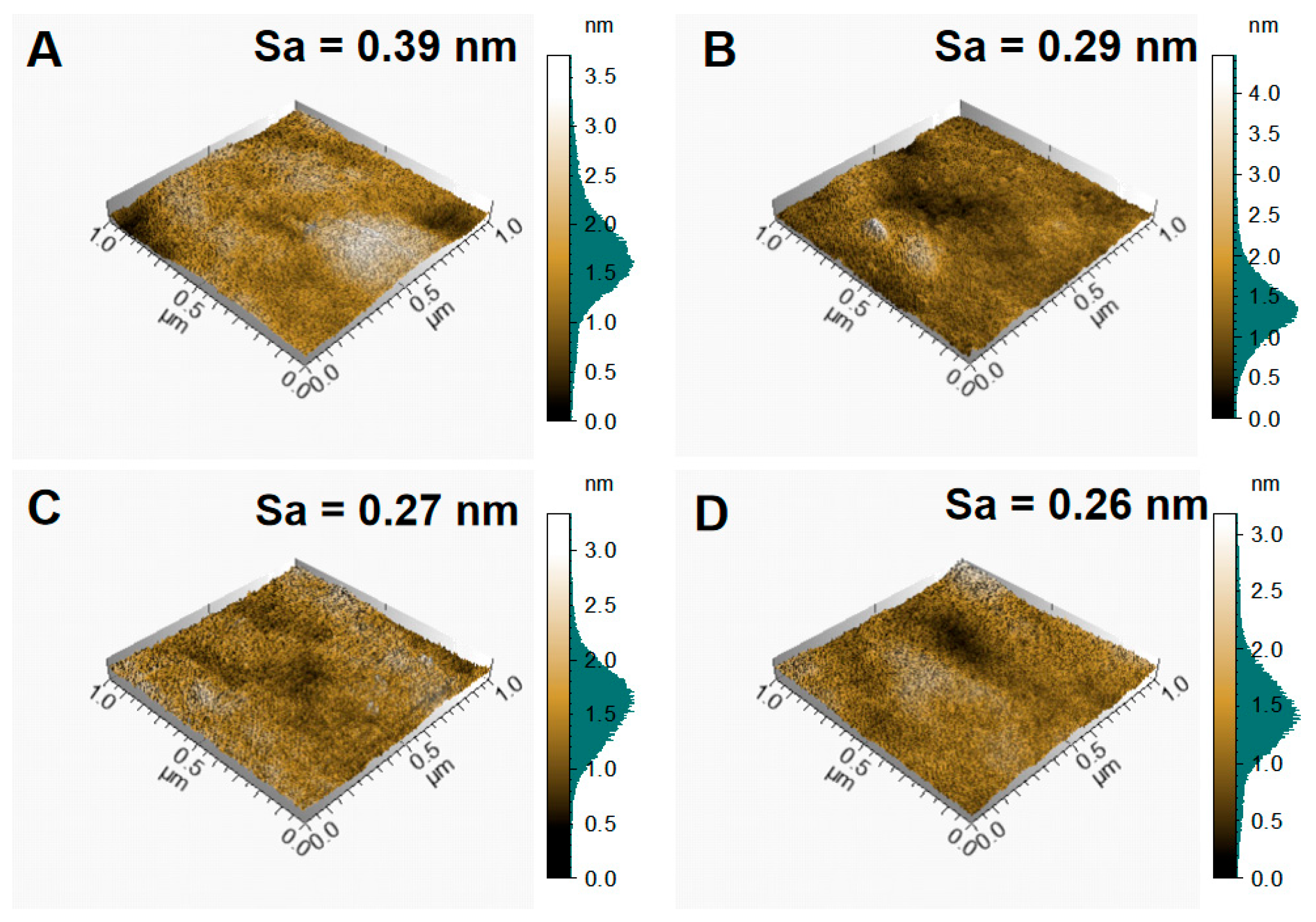
As shown in Figure 2D–F, the surface morphologies of the films deposited at different gas flow rates are all dense and flat. Figure 3 presents the AFM three-dimensional surface topographies and corresponding average surface roughness (Sa) values of NiCr-DLC films at different flow rates, with Figure 3A depicting the Si substrates’ surface morphology. The results indicate that as the C2H2 flow rate increases from 5 sccm to 55 sccm, the film’s surface roughness decreases progressively from 0.29 to 0.26 nm, remaining consistently lower than that of the Si substrate. Moreover, the AFM topographies reveal that, compared to the Si substrate, increasing C2H2 flow rates lead to a significant reduction in the height of nanoscale surface particles, and a gradual decrease in their radius. These findings suggest key conclusions: NiCr-DLC films, formed by the ternary co-deposition of Ni, Cr, and C, substantially reduce surface roughness.
The X-ray diffraction patterns of NiCr-DLC films deposited under different C2H2 flow rates are shown in Figure 4. The diffraction peaks observed near 43°, 50°, and 74° correspond to the substrate peaks. In addition, according to the ICSD 01-1258, the (1 1 1), (2 0 0) and (2 2 0) diffraction peaks of metallic Ni phase are located at 44.37°, 51.60°, 76.08°, respectively, where the preferred orientation is along the (111) plane, revealing the well-defined crystalline phase with face-centered cubic structure; meanwhile, the diffraction peaks of 56.30°and 67.10°are in good accordance with the lattice plane (102) and (110) of Cr2C phase (PDF#14-0519), exhibiting a preferred orientation along the (110) direction, the peak (110) intensity decreases as the increase in carbon content. The preferred orientation is commonly governed by the surface energy [35]. Research found that nanocrystallites can decrease their free energy through transforming preferential orientation [36]. Therefore, the preferential growth of the (111) and (110) planes is attributed to their low surface energy. Meanwhile, the decrease in intensity of the (110) peak suggests that, with increasing gas flow rate, the grain size gradually decreases and the amorphous content increases [37].
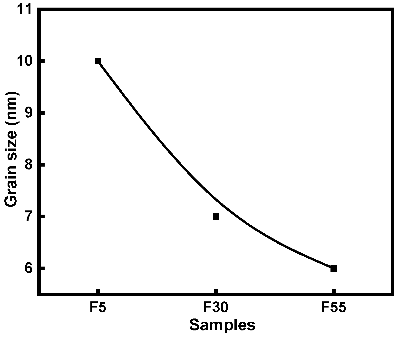
The grain sizes of NiCr-DLC films at different C2H2 flow rates, calculated using the Scherrer equation, are shown in Figure 5. With increasing gas flow rate, the average grain size decreases from 10 nm to 6 nm, corresponding to nanocrystallites of metallic Ni and Cr2C. This grain refinement is ascribed to the inhibition of crystallite growth by the surrounding amorphous carbon matrix as the carbon content increases.
Figure 6 presents the Raman spectra of NiCr-DLC films deposited at different C2H2 flow rates. As shown in Figure 6, with increasing gas flow rate, all samples exhibit a broad and asymmetric Raman scattering band within the range of 1000–1700 cm−1. This enhanced signal can be attributed to the G and D bands of hydrogenated amorphous carbon (a-C:H), located at approximately 1570 cm−1 and 1350 cm−1, respectively [38,39]. The G band corresponds to the bond-stretching vibrations of sp2-hybridized carbon atoms in aromatic rings and chains, whereas the D band originates from the breathing modes of sp2 carbon atoms in aromatic rings [40,41]. These features are characteristic of an amorphous carbon structure. Furthermore, as the C2H2 flow rate increases, the peak intensities and integrated areas of the Raman spectra for samples F5, F30, and F55 progressively increase, indicating a gradual rise in the amorphous carbon content within the films.
Table 1 summarizes the Raman spectral parameters of NiCr-DLC films deposited at different C2H2 flow rates, including the variation trends of the G-peak position, the full width at half maximum (G-FWHM), and ID/IG. As the C2H2 flow rate increases from 5 to 55 sccm, a slight blue shift in the G-peak position is observed, indicating an increase in the sp2-bonded carbon fraction. This phenomenon may be attributed to the incorporation of Cr atoms, which consume part of the sp3-bonded carbon to form carbides. In addition, the non-carbide-forming element Ni can act as a catalyst, promoting the conversion of sp3 bonds into sp2 bonds. With increasing gas flow rate, the ID/IG ratio increases from 0.63 to 0.66 and further to 1.17, suggesting a progressive increase in the defect density within the films. Furthermore, sample F30 exhibits the smallest G-FWHM value, indicating the highest degree of carbon lattice ordering, a more uniform carbon network, and a tendency toward enhanced structural stability of the film.
Furthermore, a detailed XPS analysis was performed on sample F55 (Figure 7). The C 1s spectrum, shown in Figure 7A, can be deconvoluted into four distinct peaks [42,43,44]. Figure 7B and Figure 8C present the Cr 2p and Ni 2p core-level spectra of sample F55, respectively. Compared with the binding energies of metallic Cr (574.25 and 583.45 eV), the Cr 2p peaks (572.82 and 582.27 eV) are shifted toward lower binding energies, indicating that carbon incorporation significantly modifies the chemical environment of Cr. The formation of covalent Cr–C bonds reduces the electron binding energy of Cr. The Cr 2p spectrum was fitted with two asymmetric line shapes corresponding to the Cr 2p3/2 and Cr 2p1/2 doublet features, and further deconvoluted into three components: Cr–Cr [45] (572.82 and 581.97 eV), Cr–C [46] (573.72 and 583.27 eV), and Cr–O (576.02 and 585.67 eV). These results indicate that the Cr species in sample F55 consist of metallic Cr–Cr, Cr–C, and Cr–O bonds. As shown in Figure 7C, the Ni 2p peaks (852.82 and 870.12 eV) exhibit a slight shift toward higher binding energies compared with those of pure metallic Ni [47] (852.70 and 870.00 eV), indicating the presence of oxidized Ni species (Ni2+or Ni3+) due to the interactions with oxygen from the chamber environment. Nevertheless, the dominant chemical state of Ni in sample F55 is still metallic Ni-Ni. Overall, these observations are consistent with the results from XRD and Raman analyses.

3.2. Mechanical Properties of NiCr–DLC Films

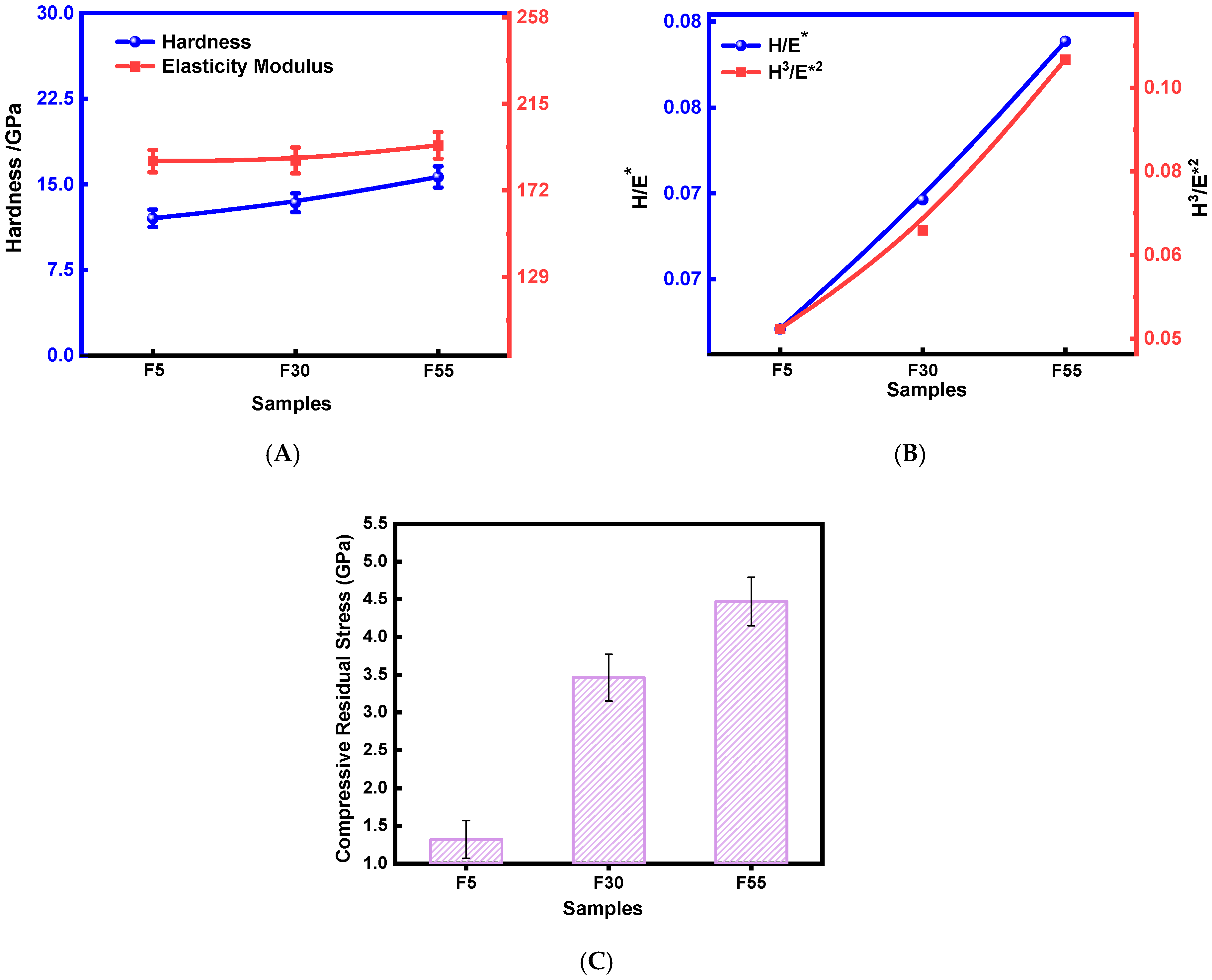
The mechanical properties of the NiCr-DLC films, including hardness (H), Young’s modulus (E), H / E * , H 3 / E * 2 and residual stress, are shown in Figure 8A–C. For sample F5, the hardness and Young’s modulus are 12.02 and 186.60 GPa, respectively. With increasing C2H2 flow rate, both hardness and Young’s modulus increase, reaching maximum values of 15.65 and 194.40 GPa, respectively, at a flow rate of 55 sccm (sample F55), as presented in Figure 8A. As reported in the literature, the H / E * ratio reflects the wear resistance of films, and films with higher H / E * values generally exhibit enhanced wear resistance [48,49,50]. A higher H 3 / E * 2 value typically indicates improved resistance to plastic deformation. Similar to the increasing trends of hardness and elastic modulus with gas flow rate, the H / E * and H 3 / E * 2 values of the films also reach their maxima, 0.08 and 0.10 GPa, respectively.
This substantial enhancement may be attributed to three mechanisms:
(i) Nanocrystalline-amorphous composite structure. Chromium acts as a strong carbide-forming element, forming covalent Cr–C bonds as evidenced by XPS (Figure 7B), leading to the precipitation of Cr–C nanoclusters or Cr2C nanocrystallites, which are further confirmed by XRD. These hard nanophases, together with metallic Ni nanograins, are embedded within the amorphous carbon (a–C) matrix, creating a nanocomposite architecture. This structure enhances hardness through interface strengthening and effectively suppresses plastic deformation, while also promoting the nucleation of the DLC phase during deposition.
(ii) Modulation of the amorphous carbon network. Increasing the C2H2 flow rate elevates the sp3/sp2 carbon ratio, as supported by XPS and Raman analyses. The resulting a-C matrix exhibits a rigid, three-dimensional covalent network with high intrinsic stress, contributing significantly to the improvement in hardness and elastic modulus. Notably, Ni serves as a catalyst for sp2 clustering: the increasing ID/IG ratio and slight downshift of the G-peak in Raman spectra indicate enhanced graphitic ordering, which optimizes the microstructure of the carbon matrix.
(iii) Internal stress relaxation and toughening. While the high sp3 content and nanocrystallite dispersion contribute to high hardness, they may also induce significant residual stress. Metallic Ni (predominantly in the Ni–Ni state, XPS Figure 7C) embedded in the matrix enables interfacial sliding, facilitating stress relaxation and preventing crack initiation. This mechanism improves toughness and adhesion without compromising overall hardness, resulting in a favorable combination of strength and durability.
Collectively, Cr and Ni play complementary roles: Cr enhances structural stability and hardness via carbide formation, while Ni promotes microstructural evolution and mitigates internal stress, thereby enabling the fabrication of DLC coatings with superior mechanical integrity.
Friction tests were conducted on the NiCr-DLC films to evaluate their wear behavior. Tribological tests were conducted as single runs in this study, and while the friction signals showed good stability, the lack of multiple trials is acknowledged as a limitation in statistical evaluation. Figure 9A illustrates the variation in the friction coefficient (COF) as a function of testing cycles. Under a test load of 1 N/2 Hz, the COF curve of sample F5 exhibits pronounced fluctuations and a relatively high average COF of 0.438. Notably, after approximately 22 min of testing, the COF undergoes a sudden fluctuation followed by a sharp increase, subsequently rising continuously to 0.430, suggesting possible surface failure of the film. For samples deposited at higher C2H2 flow rates, the running-in period of the COF curve is shorter, enabling the films to reach a steady-state regime more rapidly. At a C2H2 flow rate of 55 sccm, a low COF of ~0.115 was observed, exhibiting significantly lower frictional behavior. Figure 9B presents the two-dimensional cross-sectional profiles of the wear tracks for NiCr-DLC films deposited at different C2H2 flow rates under the 1N/2 Hz condition. At a C2H2 flow rate of 5 sccm, the wear track is relatively wide and deep, with a depth of approximately 1.20 µm. As the C2H2 flow rate increases, both the width and depth of the wear track gradually decrease. Notably, the wear depth of sample F55 is only about 0.14 µm, demonstrating excellent wear resistance. Small peaks are observed at the edges of the profiles between the wear tracks and the film surface, primarily due to the accumulation of wear debris and substrate deformation induced by extrusion from the counterpart material [51].
Table 2 presents the friction coefficients and wear rates of NiCr-DLC films deposited at different C2H2 flow rates. As the C2H2 flow rate increases from 5 to 55 sccm, the wear rate of the coatings decreases significantly from 1.18 × 10⁻⁴ to 4.45 × 10⁻⁷ mm3/(N·m), with sample F55 exhibiting the lowest wear rate. These results indicate that the tribological performance of NiCr-DLC films can be substantially enhanced by optimizing the deposition parameters [52,53].
Table 2. Friction coefficient and wear rate for different samples.
SamplesFriction CoefficientWear Rate mm3/(N·m)
F50.415 ± 0.0031.18 × 10−4
F300.182 ± 0.0022.30 × 10−6
F550.115 ± 0.0014.45 × 10−7
To further investigate the friction mechanisms, the optical microscopy images of the wear tracks of NiCr-DLC films deposited at various C2H2 flow rates are presented in Figure 10 [33]. At a flow rate of 5 sccm (Sample 5), cracks are observed on the wear scar after the friction test. For all samples, a substantial amount of wear debris accumulates on both sides of the wear track, while only patchy debris is observed on the wear surface. This observation suggests that the debris forms within the wear track and is subsequently removed from the wear scar during sliding [53,54]. When the C2H2 flow rate is increased to 30 sccm, plough marks appear on the wear track, attributed to the action of abrasive particles [55]. The width of the wear track of 55 sccm is narrow, and no cracks or spallation are observed on the wear track. The sample F55 exhibits the lowest COF (0.115) and wear rate (4.45 × 10⁻⁷ mm3/(N·m)). The experimental results demonstrate that the wear resistance of NiCr-DLC films improves progressively with increasing C2H2 flow rate.
This enhancement can be attributed to two factors:
(i) Increased hardness (H) and H/E* ratio [56]: As the C2H2 flow rate increases from 5 to 55 sccm, hardness rises from 12.02 to 15.65 GPa, accompanied by a corresponding increase in H/E* (Figure 8). The higher hardness and a stiffer interface effectively suppress plastic deformation and crack propagation, thereby reducing wear debris generation and substrate damage [57].
(ii) Modulation of amorphous carbon phase structure: XPS and Raman analyses reveal that increasing the C2H2 flow rate from 5 to 55 sccm significantly enhances the amorphous carbon (a-C) content in the films, with carbon concentration rising from 17.79% to 56.79%. The I D / I G ratio increases from 0.63 to 1.17 (Table 1), indicating pronounced graphitization of the amorphous carbon phase and the formation of a graphite-like structure dominated by sp2 hybridization. This structural transformation enhances wear resistance by reducing the interfacial friction coefficient and facilitating the formation of a protective transfer film. Moreover, the high intrinsic stress (4.47 GPa, Figure 8C) of the a-C phase suppresses crack initiation and propagation through lattice distortion, further decreasing both the width and depth of the wear track. It should be noted that the wear mechanism analysis was based primarily on wear track morphology and friction behavior, as direct compositional analysis of wear debris and transfer films was not performed in this study.
By integrating the wear track morphology with tribological performance data, an evolution model of the friction mechanism for NiCr–DLC coatings can be proposed:
1. Low gas flow stage (5 sccm): Adhesive wear is predominant, accompanied by substantial wear debris accumulation and pronounced plastic deformation of the substrate.
2. Medium gas flow stage (30 sccm): Adhesive and abrasive wear coexist, with ploughing features progressively emerging on the wear track.
3. High gas flow stage (55 sccm): Abrasive wear becomes dominant, while the self-lubricating effect of the amorphous carbon phase and the reinforcement provided by nanocrystalline phases act synergistically, leading to a gradual reduction in wear rate.
The potentiodynamic polarization curves of the NiCr-DLC films in 3.5% NaCl solution are presented in Figure 11. The corrosion potential ( E c o r r ) and corrosion current density ( I c o r r ) values were obtained via Tafel extrapolation using linear fitting and are summarized in Table 3. It is widely recognized that the corrosion resistance kinetics of materials are commonly evaluated using the I c o r r value [58], since the corrosion rate is directly proportional to I c o r r . The I c o r r was determined by extrapolating the cathodic Tafel slopes to the corrosion potential [59]. E c o r r denotes the corrosion potential, R p represents the polarization resistance, and β a and β c correspond to the Tafel coefficients for the anodic and cathodic branches, respectively.
Notably, the corrosion potential of the NiCr-DLC films is higher than that of AISI 304L, indicating that their ionization during corrosion is more difficult, thereby leading to a reduced tendency to corrode. Among the NiCr-DLC films, sample F55 exhibits the lowest corrosion tendency based solely on its corrosion potential ( E c o r r = 0.083   V ). Furthermore, R p for sample F55 reaches a maximum of 2.76 × 10⁵ Ω/cm2.
The corrosion potential can be used to evaluate the corrosion tendency of a sample. However, analyzing the corrosion dynamics requires consideration of both the corrosion rate and the corrosion current density. As shown in Table 3, I c o r r for sample F5 is 6.82 × 10⁻⁷ A/cm2. This value decreases markedly to 1.22 × 10⁻⁷ A/cm2 when the C2H2 flow rates increase to 55 sccm. It is worth noting that the I c o r r of the NiCr-DLC films is lower than that of AISI 304L, indicating that the coatings possess enhanced corrosion resistance. The fitted curves are presented in the Nyquist and Bode plots (Figure 11B–D). In Figure 11B, the Nyquist plot of the NiCr-DLC films exhibits a semicircular arc corresponding to capacitive reactance. It is observed that when the C2H2 flow rate is 55 sccm, the radius of the capacitive reactance arc is the largest. A larger arc radius corresponds to higher resistance during corrosion, thereby indicating better corrosion resistance. Hence, the NiCr-DLC films exhibit the best corrosion resistance of the NiCr-DLC films at 55 sccm. According to Figure 11C,D, the impedance phase angles in the Bode plots of the NiCr-DLC films show similar changes with frequency. The Nyquist plot suggests the presence of at least two time constants, as evidenced by the broad impedance peak observed at a flow rate of 55 sccm. The impedance amplitudes of the NiCr-DLC films remain nearly constant in the high-frequency region, consistent with the constant impedance observed in the same electrolyte in this study. At the lowest frequency, the impedance amplitudes |Z| of the NiCr-DLC films exceed 1.1 × 10⁴ Ω /cm2. Among the different flow rates, the NiCr-DLC films with a flow rate of 55 sccm exhibit the largest impedance amplitude |Z|, with a value of 1.68 × 10⁵ Ω/cm2. These results indicate that an appropriate gas flow rate can enhance the corrosion resistance of the NiC-DLC films.

4. Conclusions

This study fabricated NiCr-DLC films with varying carbon contents by adjusting the C2H2 flow rate via FCVAD technology and systematically investigated the effects of carbon content on the film’s structure, hardness, tribological behavior, and corrosion resistance. The experimental results showed that increasing the C2H2 flow rate from 5 to 55 sccm raised the carbon content in the films from 17.79% to 56.79%. Combined XRD, XPS, SEM, and Raman analyses consistently confirmed that the films possessed a typical nanocomposite structure, comprising Ni and Cr2C nanocrystalline grains embedded within an amorphous carbon (a-C) matrix.
The hardness of the NiCr-DLC films increased progressively with the C2H2 flow rate, from 12.02 GPa at 5 sccm to 15.56 GPa at 55 sccm. The co-doping of Ni and Cr into the DLC matrix effectively balances the mechanical properties of the films, particularly in terms of hardness and toughness. In this nanocomposite system, Cr plays a key role in enhancing hardness through the formation of nanocrystalline Cr2C domains dispersed within the amorphous carbon (a-C) network. Meanwhile, Ni contributes to improved toughness by promoting energy dissipation mechanisms and mitigating brittle fracture, thereby reducing the susceptibility to crack initiation and propagation.
From a corrosion resistance standpoint, the synergistic effect of Ni and Cr is also evident. Cr readily forms a protective, passive Cr2O3 layer on the surface, which acts as a barrier against corrosive species. Concurrently, Ni enhances the electrochemical stability of the film, further suppressing anodic dissolution. This dual protection mechanism results in significantly reduced corrosion current density ( I c o r r ) and improved overall corrosion resistance compared to the substrate.
Finally, AFM measurements revealed a well-defined linear decrease in surface roughness with increasing carbon content. The Ni-Cr-C co-deposited DLC-based films significantly reduced surface roughness, with all samples exhibiting values (0.26–0.29 nm) lower than that of the Si substrate (0.39 nm), demonstrating excellent surface smoothness. With increasing carbon content, the film microstructure evolves from a columnar to a more homogeneous and densely packed nanocomposite structure. This transition, driven by the suppression of columnar growth and enhanced amorphization, leads to a progressive reduction in surface roughness, as confirmed by AFM measurements. The resulting ultrasmooth surface not only improves tribological performance under dry sliding conditions but also minimizes potential sites for localized corrosion initiation.
Collectively, these factors contribute to the superior multifunctional performance observed in the NiCr-DLC films, particularly in sample F55, highlighting their promising potential for advanced protective coating applications in demanding environments.
The conclusions of this study are based on a controlled set of deposition parameters and characterization techniques. While the results demonstrate clear trends, future work should expand the parameter space, increase sample size, and incorporate advanced analytical methods to further validate the proposed mechanisms.

Author Contributions

Validation, X.P., S.W. and X.Z.; investigation, B.Z. and L.Z.; writing—original draft, B.Z.; project administration, X.O. and B.L.; funding acquisition, X.O. All authors have read and agreed to the published version of the manuscript.

Funding

This research was funded by the National Natural Science Foundation of China (No. 12175019).

Institutional Review Board Statement

Not applicable.

Informed Consent Statement

Not applicable.

Data Availability Statement

The data presented in this study are available on request from the corresponding author.

Conflicts of Interest

The authors declare no conflicts of interest.

References

  1. Rajak, D.K.; Kumar, A.; Behera, A.; Menezes, P.L. Diamond-Like Carbon (DLC) Coatings: Classification, Properties, and Applications. Appl. Sci. 2021, 11, 4445. [Google Scholar] [CrossRef]
  2. Sahay, S.; Pandey, M.K.; Kar, A.K. Nickel concentration dependent mechanical and tribological properties of subsurface layer of electrodeposited Ni-C nanocomposite thin films. Thin Solid Film. 2023, 773, 139818. [Google Scholar] [CrossRef]
  3. Liu, X.; Jin, P.; Shu, Z.; Yang, Y.; Gui, B.; Cui, Q.; Wang, J.; Ding, J.; Zhang, S.; Zheng, J. Regulating the structure and performance of amorphous carbon-based films by introducing different interlayers for applications in PEMFC bipolar plates. Surf. Coat. Technol. 2024, 487, 131000. [Google Scholar] [CrossRef]
  4. Dai, W.; Wang, A. Synthesis, characterization and properties of the DLC films with low Cr concentration doping by a hybrid linear ion beam system. Surf. Coat. Technol. 2011, 205, 2882–2886. [Google Scholar] [CrossRef]
  5. Chang, Y.-Y.; Yang, S.-J.; Wang, D.-Y. Characterization of TiCr(C,N)/amorphous carbon coatings synthesized by a cathodic arc deposition process. Thin Solid Film. 2007, 515, 4722–4726. [Google Scholar] [CrossRef]
  6. Zhang, S.; Bui, X.L.; Jiang, J.; Li, X. Microstructure and tribological properties of magnetron sputtered nc-TiC/a-C nanocomposite. Surf. Coat. Technol. 2005, 198, 206–211. [Google Scholar] [CrossRef]
  7. Dub, S.; Pauleau, Y.; Thièry, F. Mechanical properties of nanostructured copper-hydrogenated amorphous carbon composite films studied by nanoindentation. Surf. Coat. Technol. 2004, 180–181, 551–555. [Google Scholar] [CrossRef]
  8. Dai, W.; Ke, P.; Wang, A. Microstructure and property evolution of Cr-DLC films with different Cr content deposited by a hybrid beam technique. Vacuum 2011, 85, 792–797. [Google Scholar] [CrossRef]
  9. Dovydaitis, V.; Milieška, M.; Chimborazo, J.; Gnecco, E.; Marcinauskas, L. The Effect of Chromium on the Microstructure and Transparency of Diamond-like Carbon Films. Processes 2025, 13, 1098. [Google Scholar] [CrossRef]
  10. Łukaszczyk, A.; Zimowski, S.; Pawlak, W.; Dubiel, B.; Moskalewicz, T. Microstructure, Micro-Mechanical and Tribocorrosion Behavior of Oxygen Hardened Ti–13Nb–13Zr Alloy. Materials 2021, 14, 2088. [Google Scholar] [CrossRef]
  11. Wang, J.; Liu, X.; Zhang, Y.; Cai, W.; Wang, L.; Tang, L. Effect of substrate bias on the microstructure and mechanical and tribological properties of ZrNbTiMo refractory high entropy alloy film. Surf. Coat. Technol. 2023, 455, 129214. [Google Scholar] [CrossRef]
  12. Liu, J.; Xiang, J.; Zuo, Z.; Xie, G.; Luo, J.; Sheng, Y. Tribological Properties of Ti-DLC Coatings on Piston-pin Surfaces. J. Wuhan Univ. Technol.-Mater. Sci. Ed. 2023, 38, 1136–1146. [Google Scholar] [CrossRef]
  13. Bootkul, D.; Saenphinit, N.; Supsermpol, B.; Aramwit, C.; Intarasiri, S. Synthesis of Ti-doped DLC film on SS304 steels by Filtered Cathodic Vacuum Arc (FCVA) technique for tribological improvement. Appl. Surf. Sci. 2014, 310, 293–299. [Google Scholar] [CrossRef]
  14. Zemek, J.; Houdkova, J.; Jiricek, P.; Jelinek, M. Amorphous carbon nanocomposite films doped by titanium: Surface and sub-surface composition and bonding. Diam. Relat. Mater. 2018, 81, 61–69. [Google Scholar] [CrossRef]
  15. Li, X.; Ke, P.; Wang, A. Ab initio molecular dynamics simulation on stress reduction mechanism of Ti-doped diamond-like carbon films. Thin Solid Film. 2015, 584, 204–207. [Google Scholar] [CrossRef]
  16. Jelinek, M.; Kocourek, T.; Zemek, J.; Mikšovský, J.; Kubinová, Š.; Remsa, J.; Kopeček, J.; Jurek, K. Chromium-doped DLC for implants prepared by laser-magnetron deposition. Mater. Sci. Eng. C 2015, 46, 381–386. [Google Scholar] [CrossRef]
  17. Zhu, L.-n.; Li, J.-c.; Kang, J.-j.; Tang, L.; Ma, G.-z.; Han, C.-h.; Shi, J.-d.; Wang, H.-d. Different Cr Contents on the Microstructure and Tribomechanical Properties of Multi-Layered Diamond-Like Carbon Films Prepared by Unbalanced Magnetron Sputtering. J. Mater. Eng. Perform. 2020, 29, 7131–7140. [Google Scholar] [CrossRef]
  18. Zheng, J.; Shang, J.; Zhuang, W.; Ding, J.C.; Mei, H.; Yang, Y.; Ran, S. Structural and tribomechanical properties of Cr-DLC films deposited by reactive high power impulse magnetron sputtering. Vacuum 2024, 230, 113611. [Google Scholar] [CrossRef]
  19. Constantinou, M.; Pervolaraki, M.; Koutsokeras, L.; Prouskas, C.; Patsalas, P.; Kelires, P.; Giapintzakis, J.; Constantinides, G. Enhancing the nanoscratch resistance of pulsed laser deposited DLC films through molybdenum-doping. Surf. Coat. Technol. 2017, 330, 185–195. [Google Scholar] [CrossRef]
  20. Shen, Y.; Luo, J.; Liao, B.; Zhang, X.; Zhao, Y.; Zeng, X.; Chen, L.; Pang, P.; Bao, F. Tribocorrosion and tribological behavior of Ti-DLC coatings deposited by filtered cathodic vacuum arc. Diam. Relat. Mater. 2022, 125, 108985. [Google Scholar] [CrossRef]
  21. Zou, C.W.; Wang, H.J.; Feng, L.; Xue, S.W. Effects of Cr concentrations on the microstructure, hardness, and temperature-dependent tribological properties of Cr-DLC coatings. Appl. Surf. Sci. 2013, 286, 137–141. [Google Scholar] [CrossRef]
  22. Ahmed, S.F.; Alam, M.S.; Mukherjee, N. Cu incorporated amorphous diamond like carbon (DLC) composites: An efficient electron field emitter over a wide range of temperature. Phys. E Low-Dimens. Syst. Nanostruct. 2018, 97, 120–125. [Google Scholar] [CrossRef]
  23. Zhang, S.; Ali, N. Nanocomposite Thin Films and Coatings: Processing, Properties and Performance; Imperial College Press: London, UK, 2007; pp. 1–615. [Google Scholar]
  24. Mohammadinia, E.; Elahi, S.M.; Shahidi, S. Structural and optical properties of Ni-embedded hydrogenated diamond-like carbon (Ni-DLC) prepared by co-deposition of RF-Sputtering and RF-PECVD method. Mater. Sci. Semicond. Process. 2018, 74, 7–12. [Google Scholar] [CrossRef]
  25. Balestra, R.M.; Castro, A.M.G.; Evaristo, M.; Escudeiro, A.; Mutafov, P.; Polcar, T.; Cavaleiro, A. Carbon-based coatings doped by copper: Tribological and mechanical behavior in olive oil lubrication. Surf. Coat. Technol. 2011, 205, S79–S83. [Google Scholar] [CrossRef]
  26. Sun, H.; Yang, L.; Wu, H.; Zhao, L. Effects of Element Doping on the Structure and Properties of Diamond-like Carbon Films: A Review. Lubricants 2023, 11, 186. [Google Scholar] [CrossRef]
  27. Liu, Y.; Guo, P.; He, X.; Li, L.; Wang, A.; Li, H. Developing transparent copper-doped diamond-like carbon films for marine antifouling applications. Diam. Relat. Mater. 2016, 69, 144–151. [Google Scholar] [CrossRef]
  28. Zhou, H.; Hou, Q.; Xiao, T.; Wang, Y.; Liao, B.; Zhang, X. The composition, microstructure and mechanical properties of Ni/DLC nanocomposite films by filtered cathodic vacuum arc deposition. Diam. Relat. Mater. 2017, 75, 96–104. [Google Scholar] [CrossRef]
  29. Chen, S.N.; Yan, W.Q.; Zhao, Y.M.; Li, Q.; Chen, L.; Ouyang, X.; Hua, Q.S.; Wu, X.Y.; Zhang, Y.F.; Liao, B.; et al. Strong amorphization of AlCrNiTiV high-entropy alloy films deposited by cofilter cathode vacuum arc deposition. Appl. Surf. Sci. 2022, 592, 153318. [Google Scholar] [CrossRef]
  30. Shen, Y.; Zhou, H.; Wang, H.; Liao, B.; Wu, X.; Zhang, X. Tribological behavior of diamond-like carbon coatings with patterned structure deposited by the filtered cathodic vacuum arc. Thin Solid Film. 2019, 685, 123–130. [Google Scholar] [CrossRef]
  31. Zhang, Y.; Zuo, T.T.; Tang, Z.; Gao, M.C.; Dahmen, K.A.; Liaw, P.K.; Lu, Z.P. Microstructures and properties of high-entropy alloys. Prog. Mater. Sci. 2014, 61, 1–93. [Google Scholar] [CrossRef]
  32. Liu, W.; Wu, B.; Liu, H.; Liu, R.; Mo, Y.; Tian, Z.; Hou, Z.; Xi, T.; Wan, Z.; Huang, C.; et al. Simulation on microstructure evolution and mechanical properties of Mg−Y alloys: Effect of trace Y. Trans. Nonferr. Met. Soc. China 2022, 32, 812–823. [Google Scholar] [CrossRef]
  33. Zhou, F.; Fu, K.; Liao, B.; Yu, J.; Yang, C.; Zhang, X. Effect of carbon content on nanostructural, mechanical and electrochemical characteristics of self-organized nc-ZrCN/a-CNx nanocomposite films. Appl. Surf. Sci. 2015, 327, 350–357. [Google Scholar] [CrossRef]
  34. Nedfors, N.; Tengstrand, O.; Lewin, E.; Furlan, A.; Eklund, P.; Hultman, L.; Jansson, U. Structural, mechanical and electrical-contact properties of nanocrystalline-NbC/amorphous-C coatings deposited by magnetron sputtering. Surf. Coat. Technol. 2011, 206, 354–359. [Google Scholar] [CrossRef]
  35. Pelleg, J.; Zevin, L.Z.; Lungo, S.; Croitoru, N. Reactive-sputter-deposited TiN films on glass substrates. Thin Solid Film. 1991, 197, 117–128. [Google Scholar] [CrossRef]
  36. Arab Pour Yazdi, M.; Lomello, F.; Wang, J.; Sanchette, F.; Dong, Z.; White, T.; Wouters, Y.; Schuster, F.; Billard, A. Properties of TiSiN coatings deposited by hybrid HiPIMS and pulsed-DC magnetron co-sputtering. Vacuum 2014, 109, 43–51. [Google Scholar] [CrossRef]
  37. Jo, Y.J.; Zhang, T.F.; Son, M.J.; Kim, K.H. Synthesis and electrochemical properties of Ti-doped DLC films by a hybrid PVD/PECVD process. Appl. Surf. Sci. 2018, 433, 1184–1191. [Google Scholar] [CrossRef]
  38. Di, Z.; Huang, A.; Fu, R.K.Y.; Chu, P.K.; Shao, L.; Höchbauer, T.; Nastasi, M.; Zhang, M.; Liu, W.; Shen, Q.; et al. Thermal stability of diamondlike carbon buried layer fabricated by plasma immersion ion implantation and deposition in silicon on insulator. J. Appl. Phys. 2005, 98, 053502. [Google Scholar] [CrossRef]
  39. Ong, C.W.; Zhao, X.A.; Cheung, J.T.; Lam, S.K.; Liu, Y.; Choy, C.L.; Chan, P.W. Thermal stability of pulsed laser deposited diamond-like carbon films. Thin Solid Film. 1995, 258, 34–39. [Google Scholar] [CrossRef]
  40. Ferrari, A.C.; Robertson, J. Interpretation of Raman spectra of disordered and amorphous carbon. Phys. Rev. B 2000, 61, 14095–14107. [Google Scholar] [CrossRef]
  41. Berndt, M.; Abrasonis, G.; Kovács, G.J.; Krause, M.; Munnik, F.; Heller, R.; Kolitsch, A.; Möller, W. Bulk diffusion induced structural modifications of carbon-transition metal nanocomposite films. J. Appl. Phys. 2011, 109, 063503. [Google Scholar] [CrossRef]
  42. Greczynski, G.; Hultman, L. X-ray photoelectron spectroscopy: Towards reliable binding energy referencing. Prog. Mater. Sci. 2020, 107, 100591. [Google Scholar] [CrossRef]
  43. Greczynski, G.; Hultman, L. The same chemical state of carbon gives rise to two peaks in X-ray photoelectron spectroscopy. Sci. Rep. 2021, 11, 11195. [Google Scholar] [CrossRef]
  44. Greczynski, G.; Hultman, L. Reliable determination of chemical state in x-ray photoelectron spectroscopy based on sample-work-function referencing to adventitious carbon: Resolving the myth of apparent constant binding energy of the C 1s peak. Appl. Surf. Sci. 2018, 451, 99–103. [Google Scholar] [CrossRef]
  45. Singh, V.; Jiang, J.C.; Meletis, E.I. Cr-diamondlike carbon nanocomposite films: Synthesis, characterization and properties. Thin Solid Film. 2005, 489, 150–158. [Google Scholar] [CrossRef]
  46. Dai, W.; Zheng, H.; Wu, G.; Wang, A. Effect of bias voltage on growth property of Cr-DLC film prepared by linear ion beam deposition technique. Vacuum 2010, 85, 231–235. [Google Scholar] [CrossRef]
  47. Bayer, B.C.; Bosworth, D.A.; Michaelis, F.B.; Blume, R.; Habler, G.; Abart, R.; Weatherup, R.S.; Kidambi, P.R.; Baumberg, J.J.; Knop-Gericke, A.; et al. In Situ Observations of Phase Transitions in Metastable Nickel (Carbide)/Carbon Nanocomposites. J. Phys. Chem. C 2016, 120, 22571–22584. [Google Scholar] [CrossRef]
  48. Zhao, Y.; Ju, P.; Liu, H.; Pei, L.; Ji, L.; Li, H.; Xue, D.; Zhou, H.; Chen, J. A strategy to construct long-range fullerene-like nanostructure in amorphous carbon film with improved toughness and carrying capacity. J. Phys. D Appl. Phys. 2020, 53, 335205. [Google Scholar] [CrossRef]
  49. Leyland, A.; Matthews, A. On the significance of the H/E ratio in wear control: A nanocomposite coating approach to optimised tribological behaviour. Wear 2000, 246, 1–11. [Google Scholar] [CrossRef]
  50. Chen, S.N.; Zhao, Y.M.; Zhang, Y.F.; Chen, L.; Liao, B.; Zhang, X.; Ouyang, X.P. Influence of carbon content on the structure and tribocorrosion properties of TiAlCN/TiAlN/TiAl multilayer composite coatings. Surf. Coat. Technol. 2021, 411, 126886. [Google Scholar] [CrossRef]
  51. Aoki, Y.; Ohtake, N. Tribological properties of segment-structured diamond-like carbon films. Tribol. Int. 2004, 37, 941–947. [Google Scholar] [CrossRef]
  52. Xu, P.; Cao, X.; Zhang, M.; Yue, W.; Zhang, G. Friction and wear behaviors of different DLC films sliding against SiC and Si3N4 balls under high relative humidity. Diam. Relat. Mater. 2020, 108, 107977. [Google Scholar] [CrossRef]
  53. Xiao, L.; Xu, Y.; Chen, Z. Fretting tribological performance of DLC, TiAlN and DLC/TiAlN coatings deposited on carburized 18CrNi4A steel. Surf. Topogr. Metrol. Prop. 2022, 10, 015009. [Google Scholar] [CrossRef]
  54. Mussa, A.; Krakhmalev, P.; Bergström, J. Sliding wear and fatigue cracking damage mechanisms in reciprocal and unidirectional sliding of high-strength steels in dry contact. Wear 2020, 444–445, 203119. [Google Scholar] [CrossRef]
  55. Rani, R.; Panda, K.; Kumar, N.; Titovich, K.A.; Ivanovich, K.V.; Vyacheslavovich, S.A.; Lin, I.N. Tribological Properties of Ultrananocrystalline Diamond Films: Mechanochemical Transformation of Sliding Interfaces. Sci. Rep. 2018, 8, 283. [Google Scholar] [CrossRef]
  56. Erdemir, A.; Martin, J.M. Superior wear resistance of diamond and DLC coatings. Curr. Opin. Solid State Mater. Sci. 2018, 22, 243–254. [Google Scholar] [CrossRef]
  57. Li, L.; Liu, L.-L.; Li, X.; Guo, P.; Ke, P.; Wang, A. Enhanced Tribocorrosion Performance of Cr/GLC Multilayered Films for Marine Protective Application. ACS Appl. Mater. Interfaces 2018, 10, 13187–13198. [Google Scholar] [CrossRef]
  58. Aliyu, A.; Srivastava, C. Microstructure-corrosion property correlation in electrodeposited AlCrFeCoNiCu high entropy alloys-graphene oxide composite coatings. Thin Solid Film. 2019, 686, 137434. [Google Scholar] [CrossRef]
  59. Zhou, H.; Chhin, D.; Morel, A.; Gallant, D.; Mauzeroll, J. Potentiodynamic polarization curves of AA7075 at high scan rates interpreted using the high field model. npj Mater. Degrad. 2022, 6, 20. [Google Scholar] [CrossRef]
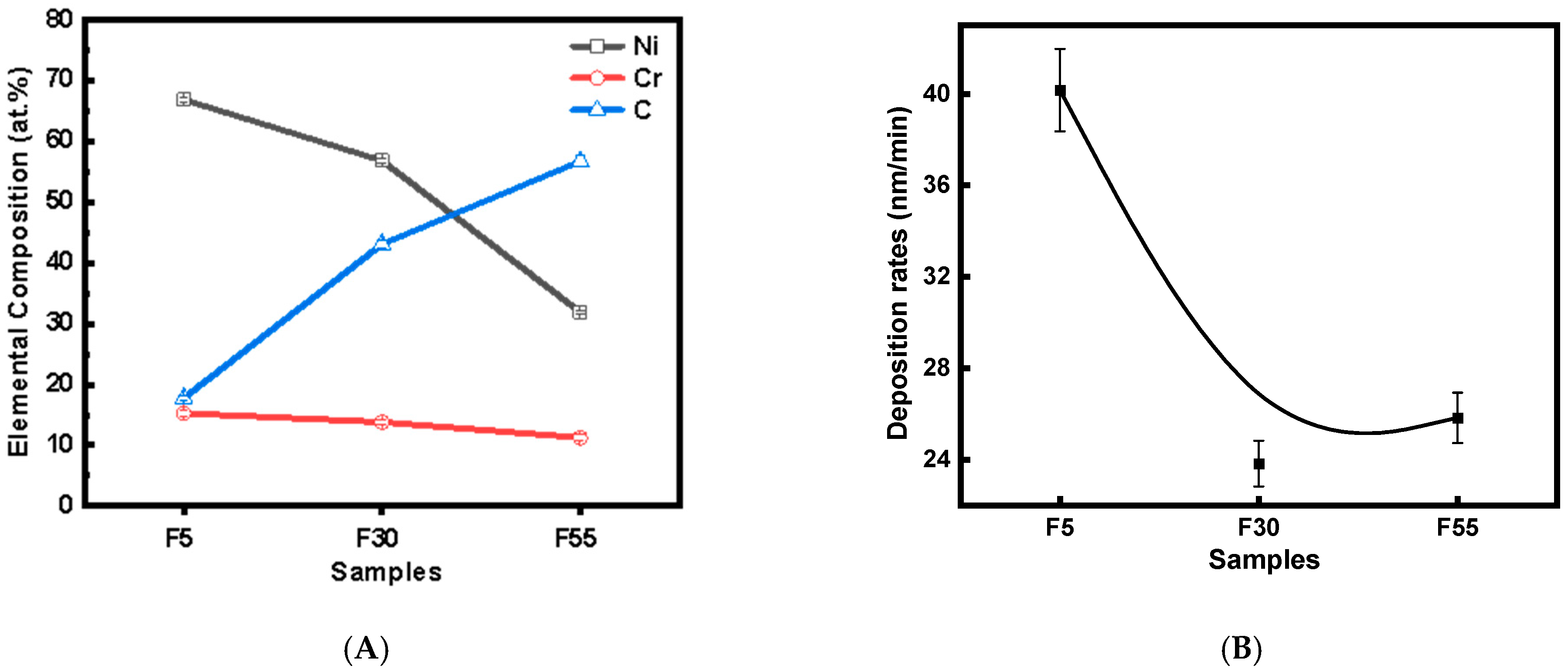
Figure 1. Element compositions of the NiCr-DLC films at different C2H2 flow rates (A). Deposition rate of NiCr-DLC films at different C2H2 flow rates (B).
Coatings 15 01136 g001
Figure 2. Cross-sectional and surface structures of NiCr-DLC films at varying C2H2 flow rates: (A,D) F5, (B,E) F30, (C,F) F55.
Coatings 15 01136 g002
Figure 3. The surface morphology and Sa roughness of NiCr-DLC films at different C2H2 flow rates: (A) Si substrate, (B) F5, (C) F30, (D) F55.
Coatings 15 01136 g003
Figure 4. The X-ray diffraction patterns of NiCr-DLC films deposited at different C2H2 flow rates.
Coatings 15 01136 g004
Figure 5. The grain size of the films at different C2H2 flow rates.
Coatings 15 01136 g005
Figure 6. Raman spectra at different C2H2 flow rates.
Coatings 15 01136 g006
Figure 7. XPS spectra of C 1s, Cr 2p and Ni2p for the sample F55, (A) C1s, (B) Cr 2p, (C) Ni2p.
Coatings 15 01136 g007
Figure 8. Mechanical properties of NiCr-DLC films: (A) Hardness and Elasticity Modulus, (B) H / E * and H 3 / E * 2 , (C) compressive residual stress at different C2H2 flow rates.
Coatings 15 01136 g008
Figure 9. Tribological behavior of NiCr-DLC films at varied C2H2 flow rates: (A) friction coefficient at 1 N/2 Hz, (B) cross-section profiles of the wear tracks.
Coatings 15 01136 g009
Figure 10. The optical microscopy images of the wear track of NiCr–DLC films at various C2H2 flow rates.
Coatings 15 01136 g010
Figure 11. The Corrosion behavior of NiCr-DLC films in 3.5wt%: (A) potentiodynamic polarization, (B) Nyquist plots, (C) Bode magnitude, (D) phase angle.
Coatings 15 01136 g011
Table 1. Parameters of Raman spectroscopy at different C2H2 flow rates.
SampleD Peak
Position/cm−1
G Peak
Position/cm−1
FWHM of D PeakFWHM of G PeakID/IG
F51417.311572.84258.03112.150.63
F301376.031572.2582.3867.580.66
F551347.161565.92347.12116.481.17
Table 3. The electrochemical parameters of samples from the polarization curves.
Samples E c o r r (V) I c o r r (A/cm2) β a (mV) β c (mV) R p (Ω/cm2)η
AISI304L−0.22 ± 0.0059.94 × 10−7 ± 0.22436.95142.914.79 × 104
F5−0.08 ± 0.0046.82 × 10−7 ± 0.12176.70236.607.36 × 10431.4%
F300.003 ± 0.0012.27 × 10−7 ± 0.15244.53181.841.87 × 10577.2%
F550.083 ± 0.0011.22 × 10−7 ± 0.17183.21280.782.76 × 10587.7%
Disclaimer/Publisher’s Note: The statements, opinions and data contained in all publications are solely those of the individual author(s) and contributor(s) and not of MDPI and/or the editor(s). MDPI and/or the editor(s) disclaim responsibility for any injury to people or property resulting from any ideas, methods, instructions or products referred to in the content.