Article

Experimental Study on Tool Performance in the Machining of AISI 4130 Alloy Steel with Variations in Tool Angle and Cutting Parameters

1
School of Physics and Mechatronic Engineering, Guizhou Minzu University, Guiyang 550025, China
2
Guiyang Xianfeng Machine Tool Co., Ltd., Guiyang 550601, China
3
School of Mechanical Engineering, Guizhou University, Guiyang 550025, China
*
Author to whom correspondence should be addressed.
Coatings 2025, 15(10), 1115; https://doi.org/10.3390/coatings15101115
Submission received: 22 August 2025 / Revised: 17 September 2025 / Accepted: 19 September 2025 / Published: 23 September 2025
(This article belongs to the Special Issue Alloy/Metal/Steel Surface: Fabrication, Structure, and Corrosion)

Abstract

The high hardness and toughness of AISI 4130 alloy present significant challenges during machining, including excessive cutting forces, rapid tool wear, and poor surface finish control. To address these issues, this study combines numerical simulation with turning experiments to systematically investigate the effects of tool geometry and cutting parameters on cutting force, temperature, and surface roughness. Through Deform-3D finite element modeling, one-factor, and orthogonal simulation tests, it was found that the optimal tool geometric combination (λs = 2°, κr = 99°, γ0 = 5°) reduces the cutting forces by 21.86% as compared to the baseline parameters. Experimental validation showed that the agreement between simulated and measured cutting forces was 86.73%–87.8%, with simulated values being 10%–13.27% higher due to idealized boundary conditions. Surface morphological analysis by Bruker Contour Elite K shows that the surface roughness of the workpiece decreases with an increasing cutting speed and increases with an increasing feed rate and depth of cut. The above studies provide a certain research basis for optimizing the tool angle and improving the cutting efficiency.

1. Introduction

AISI 4130 chromium–molybdenum alloy steel is widely used in the manufacture of critical aerospace components (e.g., engine rotors) and oil drilling equipment due to its excellent strength-to-weight ratio and fatigue resistance [1,2,3]. However, the high hardness and toughness of this material also bring a series of machining challenges, such as rapid tool wear, excessive cutting forces, difficulties in controlling surface quality, and high cutting temperatures [4,5,6]. These problems not only increase the machining cost but also directly affect the manufacturing accuracy and final service performance of the parts [7,8,9].
In order to cope with the difficulties of machining high-hardness and high-toughness materials, studies have been carried out to explore them through experiments and finite element simulation methods [10,11,12]. Özel et al. [13] developed a finite element model for orthogonal cutting of AISI 1045 steel using the explicit dynamic Arbitrary Lagrangian–Eulerian (ALE) method and successfully predicted the chip morphology, temperature field, and stress distribution. Usca et al. [14] used Al/TiN-coated tools to machine Cu-B-CrC composites and found that the ratio of reinforcing phases was the key factor affecting surface roughness, tool wear, and cutting temperature. Increasing the cutting speed reduces the surface roughness but increases tool wear; increasing the feed increases the roughness, and the combined effect is synergistically regulated by the ratio of cutting speed to enhanced phase. Şap et al. [15] pointed out through turning experiments that the volume fraction of the particulate reinforcing phase significantly affects the surface roughness, tool wear, and cutting temperature of copper/molybdenum–silicon carbide composites, and that the change in the reinforcement rate also induces a change in the chip morphology and wear mechanism. Demirpolat et al. [16] used a two-level full factorial experimental design to systematically analyze the effects of three core parameters, namely, cutting speed, depth of cut, and feed rate, as well as the cutting environment. Liu et al. [17] developed a wear prediction model based on finite element simulation for the tool wear problem during end milling of titanium alloy TC4, which revealed the law of wear change with time and provided a reliable simulation tool for optimizing the machining parameters of titanium alloys and extending the tool life.
When machining high-hardness and high-toughness materials such as AISI 4130, the reasonable selection of the tool angle is especially critical to inhibit work hardening, control cutting forces, and improve heat dissipation. However, there is still a relative lack of research on the mechanism of the effect of the tool geometric angle on cutting forces and cutting temperatures. Shi et al. [18] proposed a tool wear evolution simulation method based on three-dimensional finite element modeling, which realized the accurate prediction of uncoated carbide tool wear in the cutting process of AISI 1045 steel, and systematically analyzed the influence of wear on the actual rake angle, cutting force, stress distribution, and temperature, which revealed the wear mechanism of the front face–chip interface, and provided a theoretical basis for the design of the tool and the optimization of the process. Liu et al. [19], on the other hand, investigated the mechanism of tool geometry’s influence on residual stresses in Inconel 718 orthogonal cutting through numerical simulations coupled with experimental validation of the Euler–Lagrange (CEL) method.
Early studies by Shaw [20] and Trent [21] laid down the basic theory of metal cutting mechanics, while modern simulation tools such as Deform-3D achieve more accurate thermal force coupling analysis, which provides a new way to study the material behavior, stress distribution, and heat transfer mechanism in the cutting zone [22,23,24]. Klocke [25] and Singh [26] emphasized the critical role of tool geometry in the cutting of difficult-to-machine materials, while Sivalingam [27] and Peng [28] concentrated on the study of the effect of cutting parameters on surface integrity. In recent years, scholars have further explored the synergistic effects of tool microgeometry and cooling strategies to extend tool life [29], and multi-objective optimization algorithms to balance surface quality and machining efficiency [30]. Studies by Özbek et al. [31] and Salur et al. [32] have shown that hybrid lubrication techniques (e.g., microlubrication MQL) are effective in reducing cutting temperature and improving surface quality.
The aim of this study is to construct a process optimization framework for practical applications by combining numerical simulation and experimental validation. Single factor and orthogonal tests were used to systematically investigate the influence laws of tool geometric angles (inclination angle, main cutting edge angle, and rake angle) and cutting parameters (cutting speed, feed, and depth of cut) on the cutting force and cutting temperature [33,34]; minimization of the cutting force was achieved by optimizing the geometric configurations of the tool [35]; and the correlation between the surface roughness of the workpiece and the cutting parameters was analyzed at the same time [36,37,38]. The experimentally calibrated finite element model is finally established to provide a theoretical basis and empirical support for the efficient machining, process optimization, and surface quality control of AISI 4130 steel.

2. Experimental Principles and Methods

2.1. Theoretical Analysis of the Cutting Process

Merchant’s assumption [39] is a classic theory in cutting mechanics. This theory is based on the premise that the tool is completely sharp, and it posits that shear stress is independent of the shear angle, while cutting force decreases as the sharpness of the tool increases. When the tool is extremely sharp, the shape of the chip and the cutting force primarily depend on the cutting speed and the rake angle. Furthermore, it is assumed that the magnitude of the shear angle ∅ is independent of shear strain and depends solely on the rake angle, cutting speed, and the mechanical properties of the material. Based on the above considerations, the following formula can be derived:
= π 4 β 2 + γ 0 2 ,
In Equation (1), β is the friction angle and γ 0 is the rake angle.
A s = A D s i n ,
F s = τ s A s = τ s A D s i n ,
In Equation (2), As is the area of the main shear plane; and AD is the area of the cutting layer. In Equation (3), Fs is the shear force along the main shear plane; and τs is the shear stress.
According to Figure 1, the relationship between cutting force, principal cutting force, and shear force can be obtained, as shown in Equations (4) and (5).
F = F s c o s ( + β γ 0 ) ,
F c = F c o s β = F s c o s ( β γ 0 ) c o s ( + β γ 0 ) ,

2.2. Analysis of the Influence of Tool Angles on the Cutting Process

Tool angles (inclination angle, main cutting edge anglen and rake angle) are key parameters that determine the cutting performance, directly affecting the machining accuracy, surface quality, and efficiency.
A positive inclination angle directs chips toward the unmachined surface, while a negative value directs them toward the machined surface. A negative inclination angle enhances tool tip strength, but an excessively large absolute value reduces strength, which is particularly noticeable during interrupted cutting. Additionally, a positive inclination angle extends the chip cooling time, reducing thermal damage to the workpiece.
Reducing the main cutting edge angle distributes cutting loads but decreases system rigidity, while increasing the main rake angle reduces back forces and improves heat dissipation efficiency but may increase surface texture.
Increasing the rake angle reduces the cutting force and temperature, but exceeding the critical value weakens edge strength. A balance between sharpness and strength must be maintained to avoid fluctuations in surface quality.
In summary, the various angles of the tool must be systematically matched to optimize the cutting force, heat dissipation, and surface quality.

2.3. Experimental Study on the Effect of Tool Angle on the Cutting Process

2.3.1. Cutting Simulation Model Establishment

Cemented carbide materials are widely used in tool manufacturing because of their outstanding wear resistance, excellent high-temperature performance, and stable resistance to chemical corrosion. The carbide tools used in this study were based on WC, a tungsten carbide-based cemented carbide. WC cemented carbide cutting tools are ultra-high-hardness, high-wear-resistant cutting tools made by a powder metallurgic process with tungsten carbide as the main hard phase and cobalt (Co) and other metals as the binder phase.
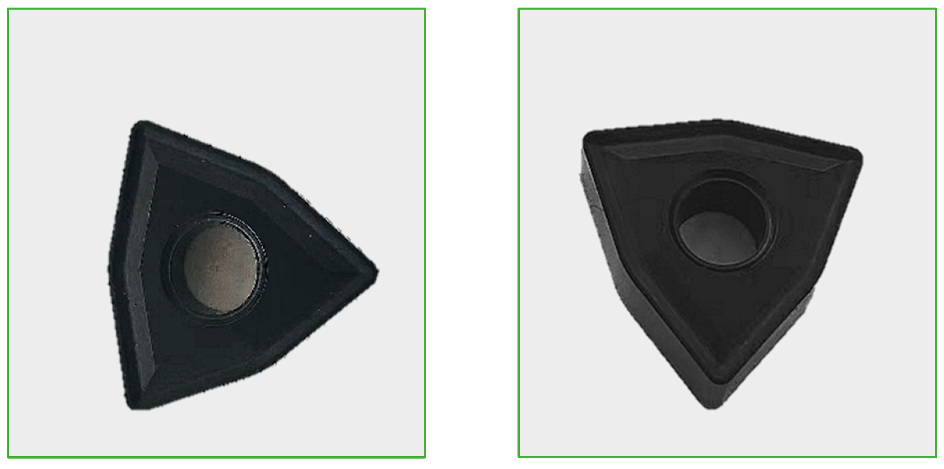
The surface of the WC carbide tool is covered with a TiAlN coating with a thickness of 5 microns. TiAlN (titanium aluminum nitride) coatings are high-performance hard coatings applied to the surface of cutting tools by the physical vapor deposition (PVD) process, which is essentially a composite material consisting of the elements titanium (Ti), aluminum (Al), and nitrogen (N), and presenting a purplish black or dark grey appearance. The core advantage of the coating is its excellent thermal stability. Under the high temperatures generated by high-speed dry cutting (up to 800–900 °C), a dense protective film of aluminum oxide (Al2O3) rapidly forms on the surface of the coating, effectively resisting further oxidation, while its low thermal conductivity acts as a thermal barrier to keep the cutting heat out of the tool. In addition, the hardness of TiAlN coatings ranges from 29.2 to 34.9 GPa, and Young’s modulus ranges from 482 to 511 GPa [40]. This is shown in Figure 2 below. WC carbide tools are one of the preferred tools for cutting AISI 4130 material.
AISI 4130 is a high-performance chromium–molybdenum alloy steel known for its well-balanced comprehensive properties. It combines high strength to withstand high-impact loads with stable performance under low-temperature conditions. The material also demonstrates good resistance to hydrogen sulfide corrosion environments and exhibits reduced susceptibility to stress corrosion cracking. Machining of AISI 4130 generally requires the use of high-performance tool materials due to its mechanical properties. The chemical composition of the workpiece material is provided in Table 1, while the physical properties of both the workpiece and cutting tool are summarized in Table 2.
During cutting operations, the contact interface between the tool and the workpiece is exposed to high temperatures and pressures. Elevated temperatures significantly enhance the diffusion of material constituents, thereby accelerating tool wear and degrading machining quality. Optimizing geometric parameters to reduce cutting temperatures and cutting forces, as well as minimizing hardening and chemical reactions during machining, plays a critical role in extending tool life and improving the surface roughness of the workpiece.
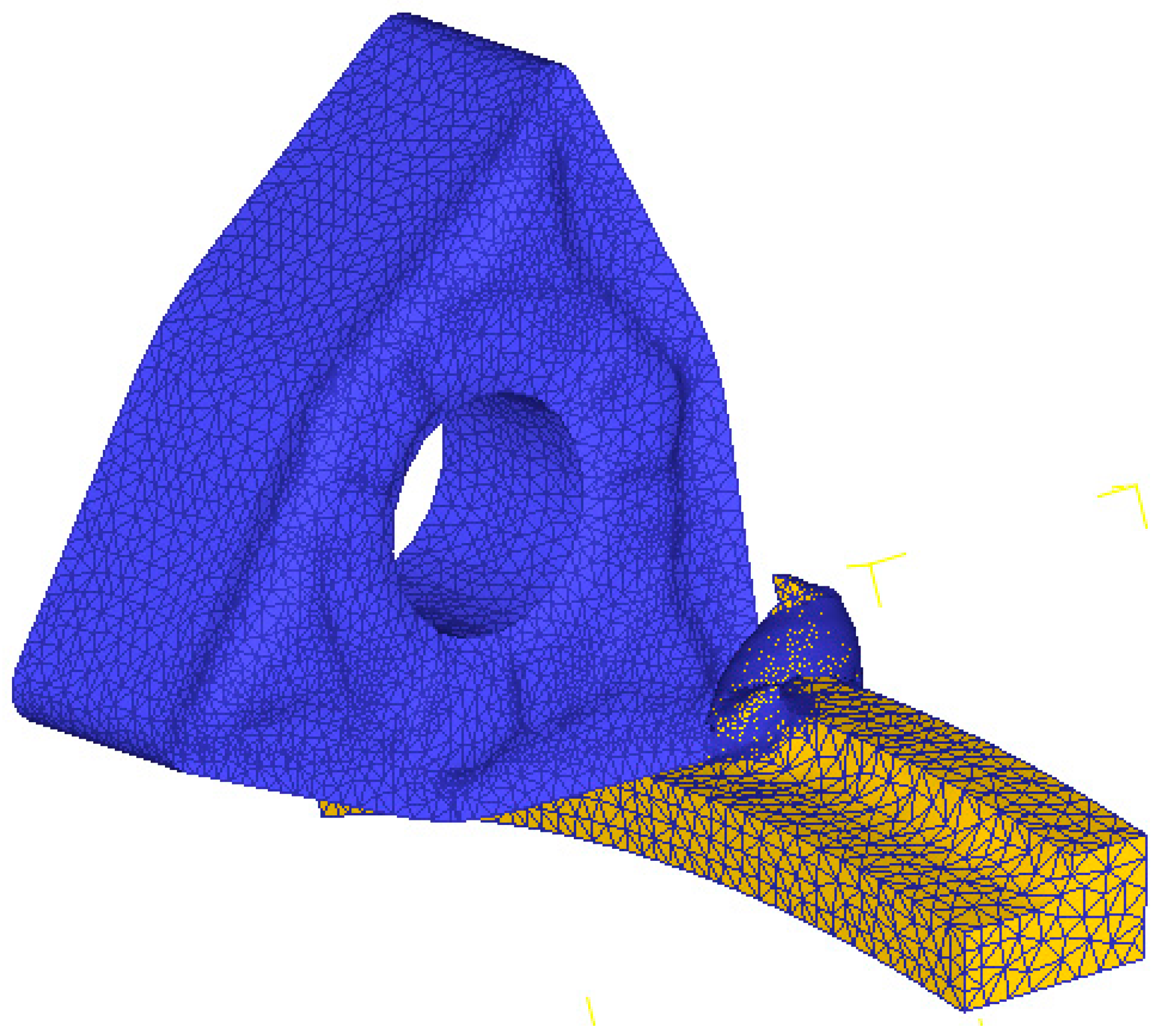
The geometric model of the cutting tool is imported into the pre-processing module of Deform. The tool model is defined as a rigid body, while the workpiece material is defined as a plastic body. The workpiece to be machined is a cylindrical body with a diameter of 100 mm and an arc angle of 20°. Based on actual cutting conditions, dynamic mesh adaptive partitioning technology is employed to discretize the mesh and construct a cutting simulation model (as shown in Figure 3).
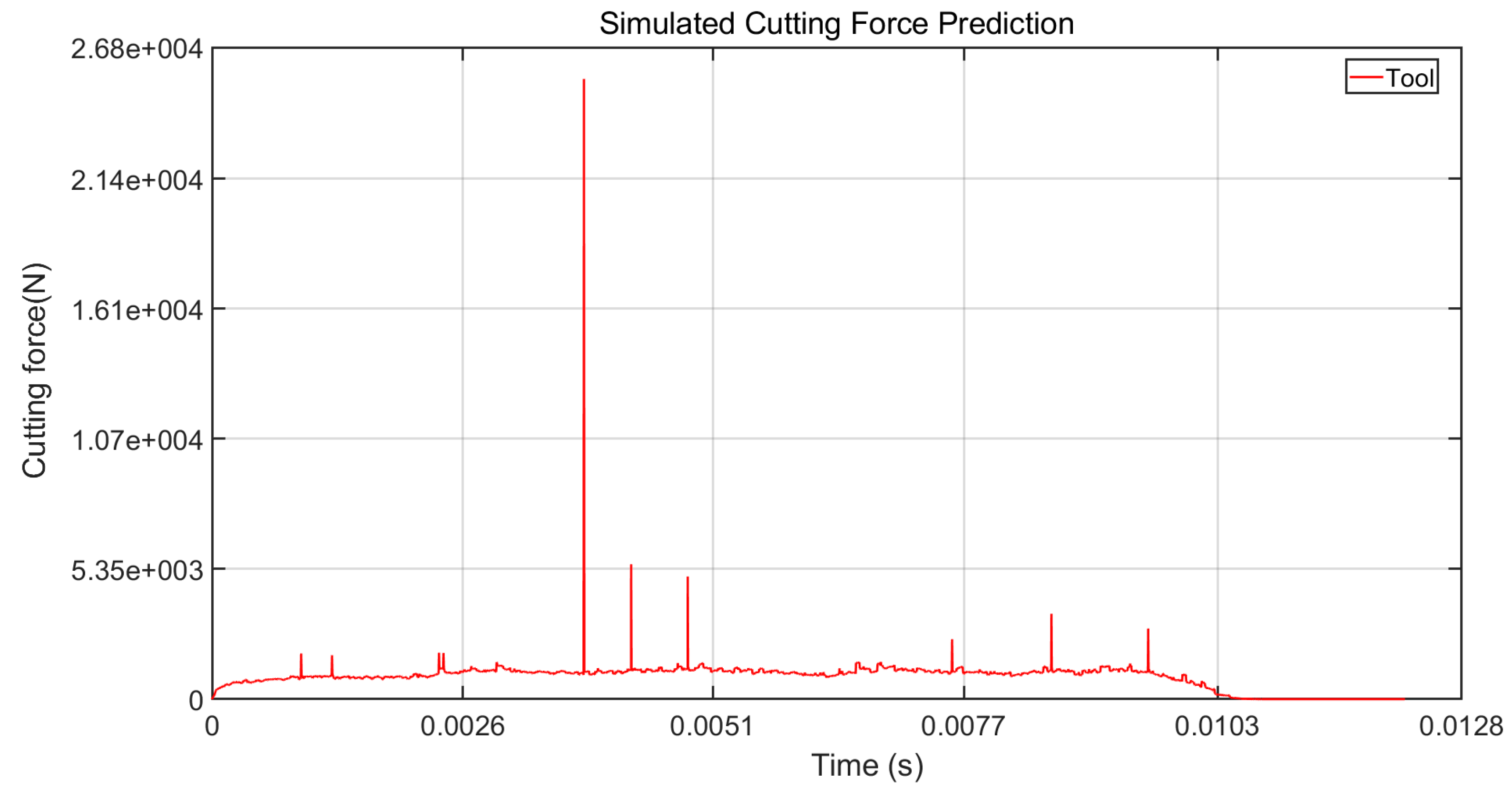
The cutting force and temperature distributions obtained from the tool simulation are shown in Figure 4 and Figure 5.
In view of the specificity of numerical simulation, the following basic assumptions were made in this study: (1) the workpiece was set to be stationary and the tool to be in rotary cutting motion around the workpiece axis when the kinematic model was established; (2) the friction coefficient at the interface between the tool and the workpiece was set to be a constant value, which was 0.4; (3) the heat exchange process between the tool and the surrounding medium was uniformly distributed; (4) the heat transfer coefficient at the interface of friction between the tool and workpiece was set to be 2000 W/(m2-K); (5) the initial temperature of both the tool and workpiece was set to be 20 °C.

2.3.2. Study on the Influence of Tool Angles on Cutting Force and Cutting Temperature

When machining AISI 4130 chromium–molybdenum alloy steel, the material exhibits severe friction and extensive plastic flow in the cutting zone, which exacerbates the force–heat coupling effect at the tool–workpiece interface. In metal cutting processes, proper geometric angles play a crucial role in determining machining quality. This section investigates the influence of the tool rake angle, main cutting edge angle, and inclination angle on the performance of the cutting zone. The principal cutting force and temperature are selected as evaluation metrics to examine the impact of individual geometric parameters. The cutting parameters used are as follows: cutting speed vc = 130 m/min, cutting depth ap = 1.1 mm, and feed rate f = 0.11 mm/r. The tool geometric parameters are configured as presented in Table 3.
A cutting simulation model was developed using the Deform-3D platform. The principal cutting force and cutting heat data for each set of experimental parameters were obtained through three-dimensional finite element analysis. The load–time and temperature–time curves during the cutting process were collected. The average values from the stable cutting phase were selected, and they are recorded as the effective simulation results in Table 4.
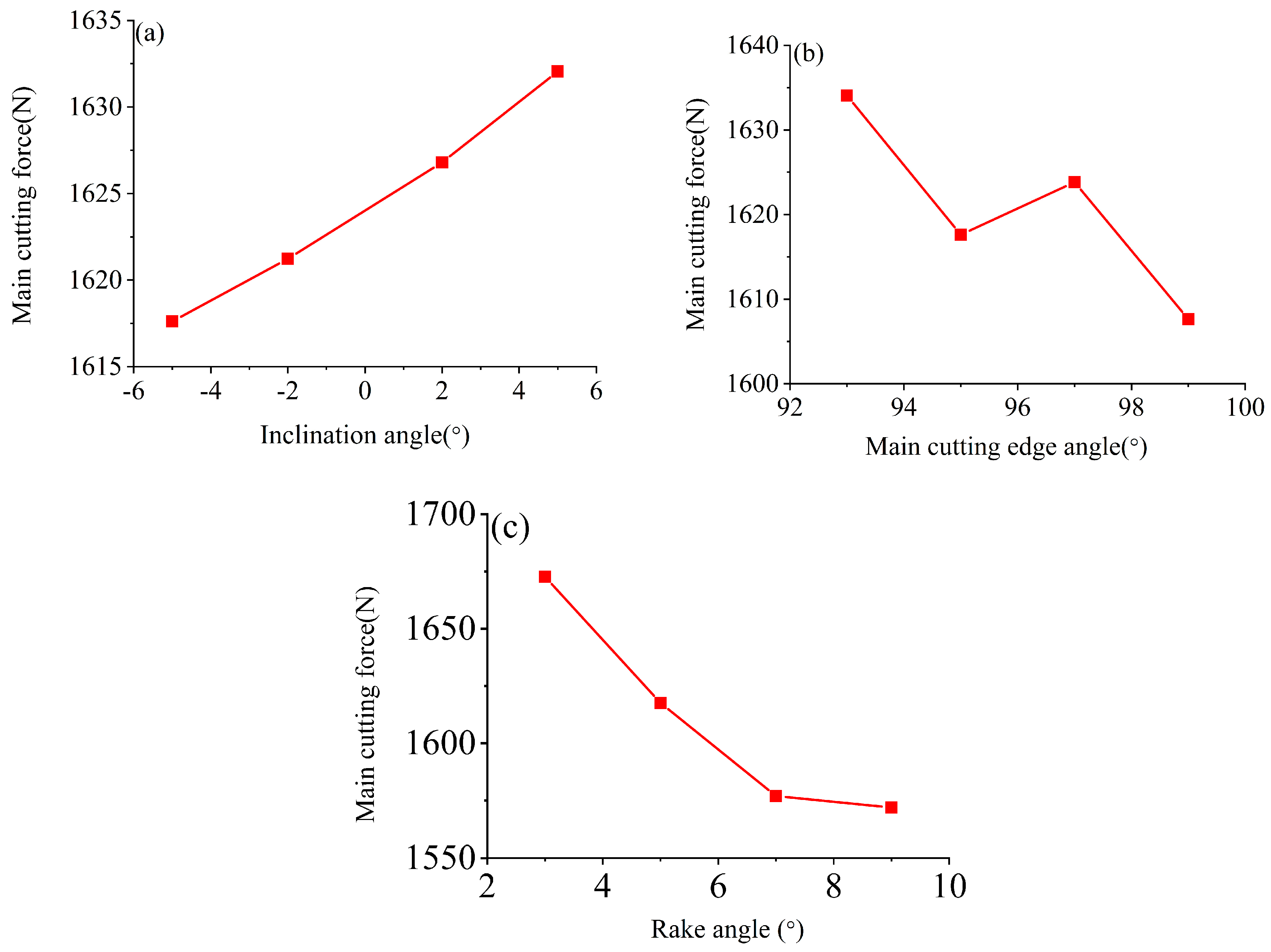
Based on this dataset, a mapping relationship between geometric angle parameters and cutting force and cutting temperature was established, and curves showing the effects of angle parameters on the main cutting force and temperature were plotted, as shown in Figure 6 and Figure 7.
Within the given parameter range, Figure 6a shows that the cutting force generally increases as the inclination angle increases. Figure 6b shows that increasing the main cutting edge angle reduces the overall cutting force. Figure 6c shows that increasing the rake angle causes an overall decrease in cutting force.
Figure 7a shows that the cutting temperature generally increases as the inclination angle increases. Figure 7b shows that the cutting temperature is positively correlated with the main cutting edge angle. Figure 7c shows that the cutting temperature is negatively correlated with the rake angle.

2.3.3. Tool Angle Optimization Based on Orthogonal Experiments

An orthogonal matrix L16(43) was used to construct a parameter combination scheme. A three-factor, four-level orthogonal experimental model was established with the inclination angle, main cutting edge angle, and rake angle as independent variables to quantitatively analyze the influence of different parameter combinations on the main cutting force.
Multiple cutting simulation experiments were conducted based on orthogonal experiments, and tool force data was exported using the Deform-3D post-processing module. To improve data reliability, each parameter combination set underwent three rounds of dataset processing.
Based on the experimental data shown in Table 5, the range was calculated to analyze the weight of the influence of different angles on the main cutting force. The results are shown in Table 6. The definitions and calculation principles of the parameters in the orthogonal experiments in Table 6 are presented as follows:
  • Meaning and principles of calculation of M1, M2, M3, M4:
  • In the polar analysis of orthogonal experiments, M1, M2, M3, and M4 represent the average of all the results of the main cutting force (Fc) corresponding to a certain geometric angle factor at each level, respectively.
  • Calculation principle: For a certain level of a factor, all rows appearing at that level were screened from all 16 sets of experiments, and the main cutting force (Fc) values corresponding to these rows were arithmetically averaged to obtain the mean value M at that level.
2.
The way in which the polar R-value is formed:
  • The extreme variance R is the difference between the maximum and minimum values of the four water means (M1, M2, M3, M4) for the same factor, i.e., R = max (M1, M2, M3, M4) − min (M1, M2, M3, M4).
  • Significance of R-value: This reflects the magnitude of the effect of the change in the level of the factor on the outcome. The larger the R-value, the more significant the change in the level of the factor is in influencing the results.
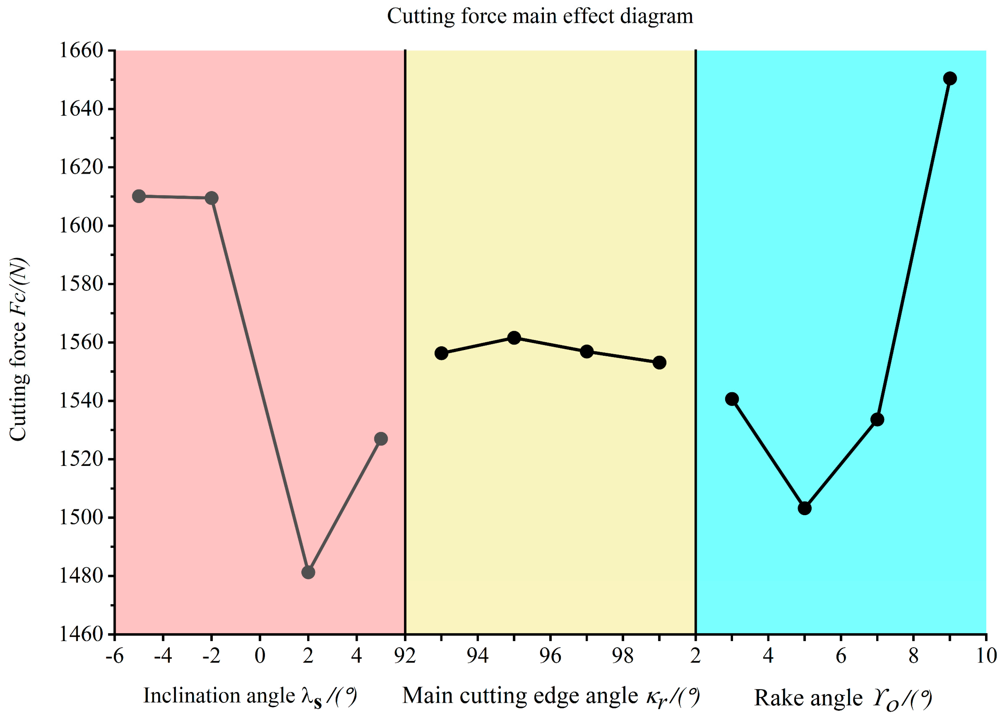
Figure 8 shows the effect of different geometric angles on the main cutting force during the cutting process. The minimum value of M is selected as the optimal parameter with the aim of reducing the main cutting force, resulting in the optimal geometric angle combination. According to Figure 8, the geometric angle combination with the smallest principal cutting force is C2A3B4, the inclination angle λs = 2°, the main cutting edge angle κr = 99°, and the rake angle γ0 = 5°.
Extreme value analysis indicates that, within a given geometric angle range, the rake angle has the most significant effect on the principal cutting force, followed by the inclination angle, while the main cutting edge angle has a relatively minor impact. During machining, to reduce the principal cutting force, the rake angle of the tool should be optimized first, followed by the selection of the edge inclination angle and main cutting edge angle.
Under simulation conditions with cutting speed vc = 130 m/min, feed rate f = 0.11 mm/r, and cutting speed ap = 1.1 mm, the optimal geometric angles are set as follows: inclination angle λs = 2°, main cutting edge angle κr = 99°, and rake angle γ0 = 5°. Under these conditions, the main cutting force decreases by 21.86%.

2.4. Study on the Influence of Cutting Parameters on the Cutting Process

2.4.1. Simulation Analysis of the Influence of Cutting Parameters on Cutting Force and Cutting Temperature

In the machining process, different cutting parameters have varying effects on workpiece processing. This section establishes a cutting process analysis model with the three cutting parameters as control variables. The experimental study in this section employs a single-variable control method to design experiments, focusing on the effects of tool cutting parameters on cutting force and cutting temperature in the cutting zone. The single-factor simulation scheme is shown in Table 7.
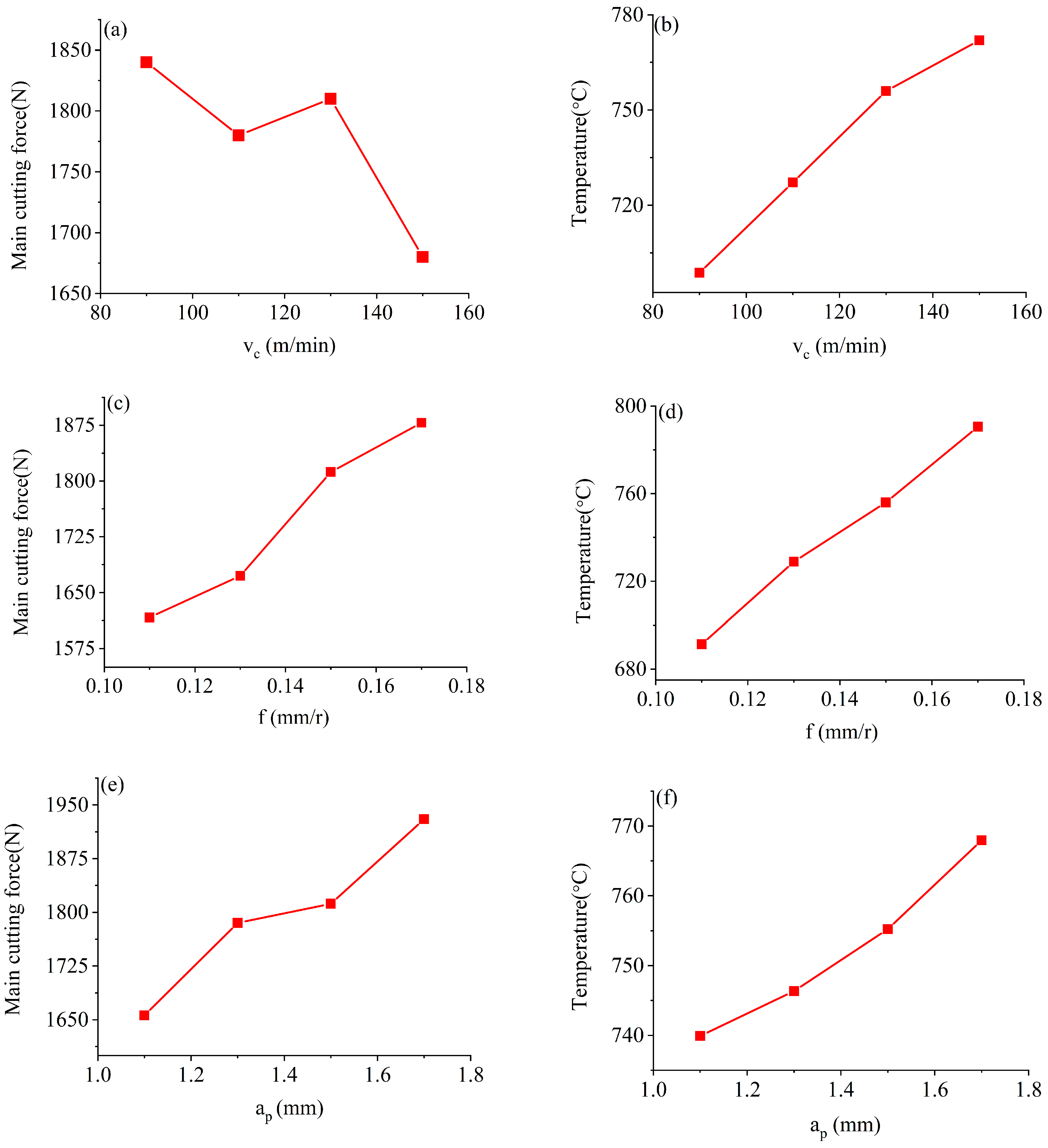
Based on the data obtained from the cutting simulation, the relationship curves be-tween the main cutting force and cutting temperature with the cutting parameters are plotted, as shown in Figure 9.
As illustrated in Figure 9a, within the tested parameter range, the overall cutting force (Fc) exhibits a negative correlation with cutting speed—higher cutting speeds result in reduced cutting forces. Conversely, Figure 9b demonstrates that the cutting temperature rises proportionally with an increasing cutting speed. A positive correlation is observed between the principal cutting force and the feed rate, as depicted in Figure 9c, while Figure 9d further confirms that the cutting temperature escalates with higher feed rates. Additionally, Figure 9e,f reveal that both the cutting force and the cutting temperature increase with greater cutting depths.

2.4.2. Turning Experiment Verification

Single-factor turning experiments were performed on a C6136HK CNC lathe, employing carbide tools with a WC substrate and TiAlN coating. The workpiece material consisted of an AISI 4130 bar stock with a diameter of 80 mm and a length of 200 mm. To evaluate the simulation model’s applicability under actual machining conditions, the experimental data was systematically compared with simulation results. During the turning process, a Kistler force gauge was utilized to measure the main cutting force, as illustrated in Figure 10. The acquired cutting force data for each tooling combination was subsequently exported via a computer for analysis.
Table 8 records the simulated and measured values of the principal cutting force under multiple cutting parameter combinations. Based on the data, trend curves of the principal cutting force as a function of cutting parameters are plotted to analyze the control mechanisms of the principal cutting force under different cutting parameter combinations.
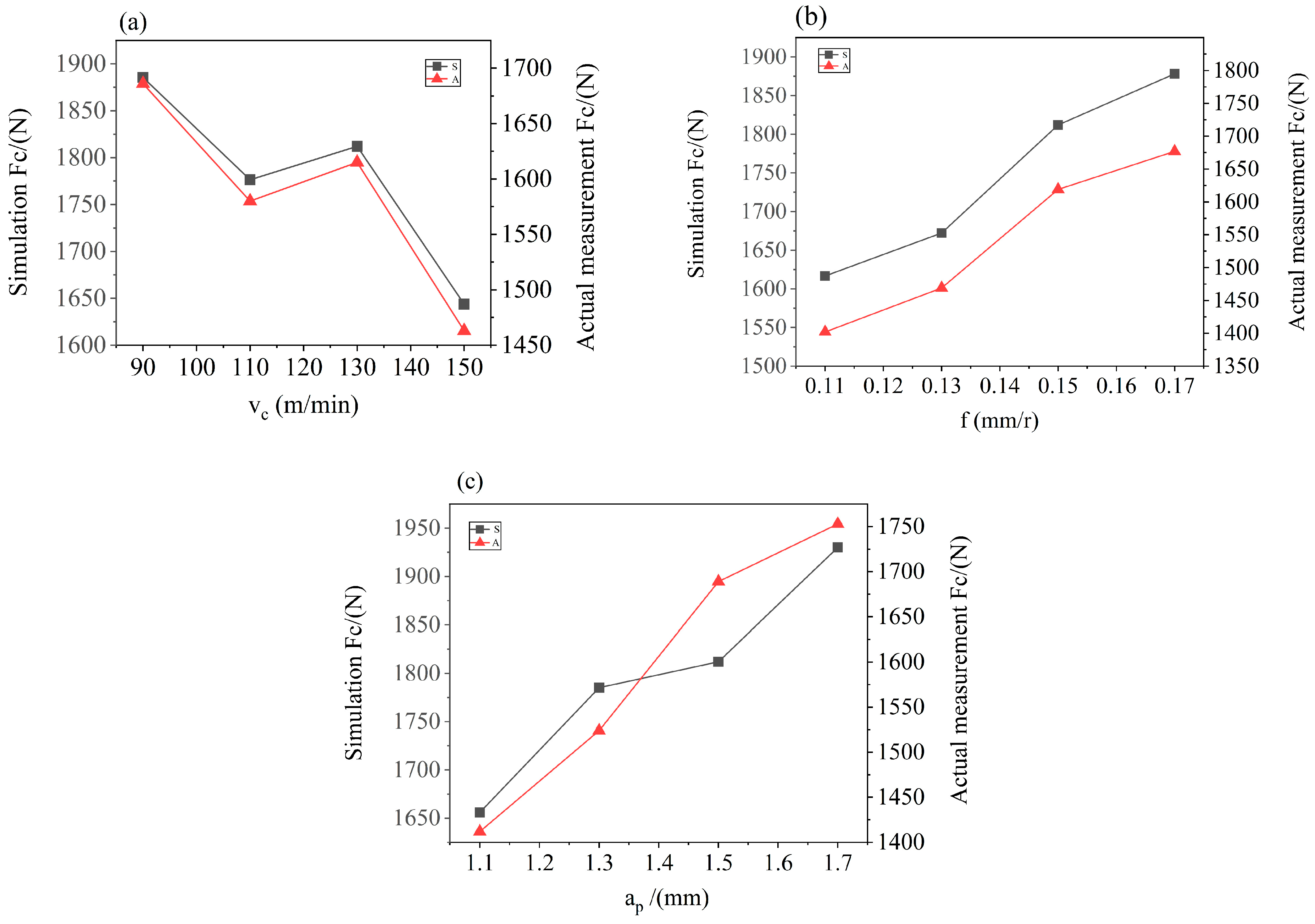
The simulated and experimentally measured results for various cutting parameters are presented in Figure 11.
According to the cutting force simulation values and actual measured values in Table 8 above, RMSE and MAPE were used as evaluation indexes for quantitative verification, and the results are shown in Table 9.
As shown in Table 8 and Table 9, under a constant feed rate and depth of cut, the simulation and experimental results exhibit a highly consistent trend regarding the variation in cutting speed gradient. As the cutting speed increases, the primary cutting force gradually decreases. However, at the same cutting speed, the simulated values are consistently approximately 12.20% higher than the experimentally measured values, which may be attributed to the simplified boundary conditions in the numerical model. The primary cutting force demonstrates a linear correlation with the feed rate; nevertheless, across all tested feed rates, the simulation results consistently overestimate the values by approximately 13.27%, potentially indicating discrepancies in energy dissipation within the virtual machining environment. Under fixed feed rate and cutting speed conditions, both datasets respond consistently to changes in depth of cut, with the simulated values exceeding the experimental measurements by approximately 12.95%.

2.4.3. Study on the Effect of Cutting Parameters on Surface Roughness

Cutting parameters directly determine the surface roughness of the workpiece. In this section, the experimental plan in Table 6 is adopted. After turning, the workpiece is placed under the Bruker Contour Elite K optical profilometer (as shown in Figure 12) to collect the surface roughness values of the machined surface.
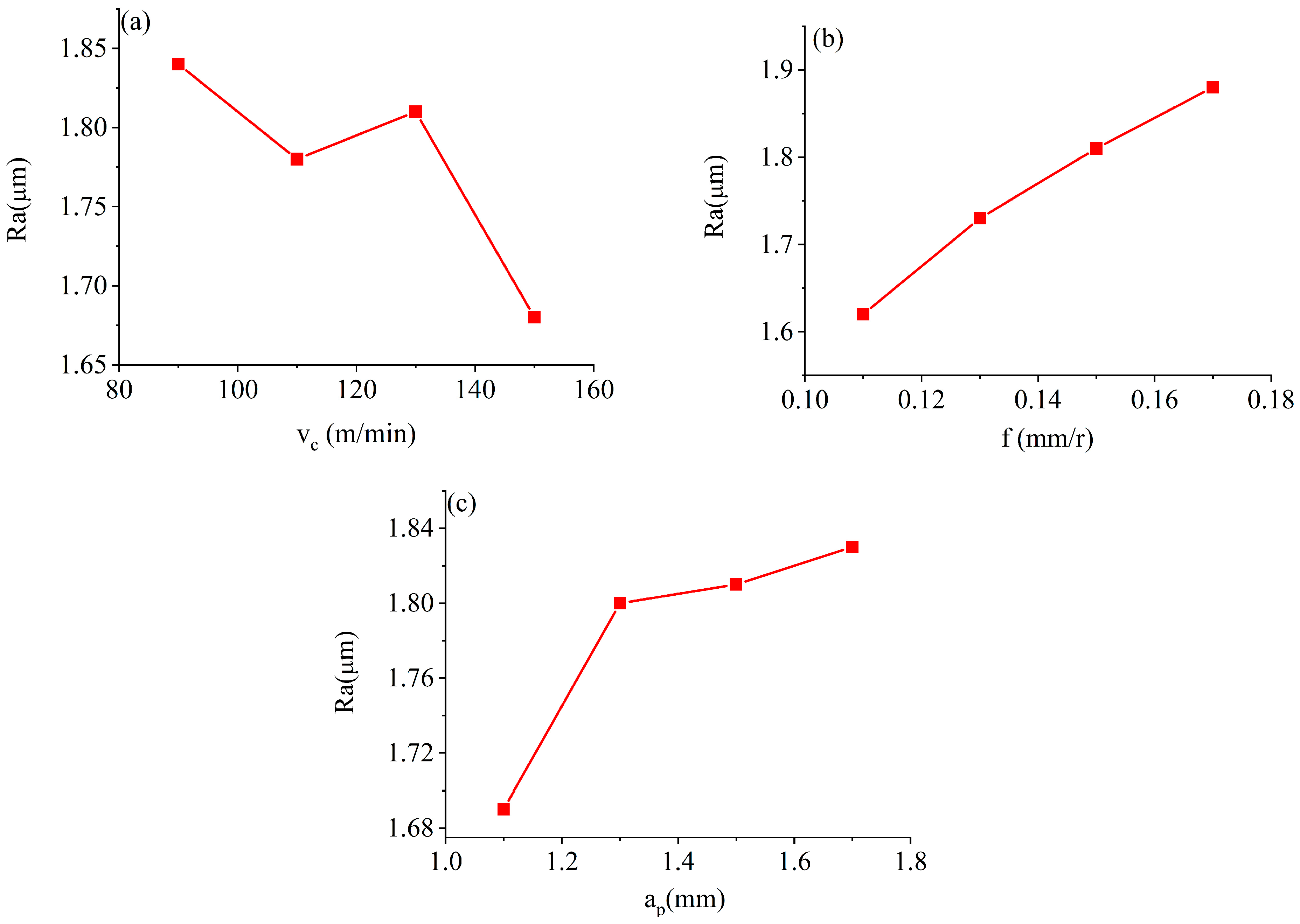
This paper primarily investigates the influence of cutting parameters (cutting speed, feed rate, and cutting depth) on surface quality. The focus of the cutting operations is mainly on semi-finishing of shaft-type components, with the desirable surface roughness (Ra) falling within the range of 1.7–1.9. Based on the measurement data, we plot the curve showing the effect of cutting parameters on the surface roughness of the workpiece, as shown in Figure 13.
Figure 13a shows a significant negative correlation between surface roughness values and cutting speed. As shown in Figure 13b, the feed rate is positively correlated with workpiece surface roughness. Figure 13c shows that as the cutting depth increases, the surface roughness of the workpiece generally increases.

3. Results and Discussion

3.1. Discussion on the Effect of Tool Angle on Cutting Force and Cutting Temperature

This paper analyzes the influence of the tool angle and the cutting parameters on the cutting performance of the tool, and it explores the relationship between the cutting parameters and the surface quality of the workpiece through the measurement of the surface roughness of the workpiece.
The cutting force increases with an increasing inclination angle. This is because when the inclination angle increases, the actual length of contact between the tool and the workpiece increases, and the length of the chip flow through the tool is extended, thus increasing the cutting resistance. As the inclination angle increases, the cutting temperature shows a decreasing and then increasing trend. This is because when the absolute value of the inclination angle is large, the effective working length of the cutting edge increases, the chip flows to the machined surface, and the frictional contact area increases, resulting in a rise in frictional heat. The overall friction between the tool and the chip is more intense when the inclination angle is positive. Therefore, the cutting temperature reaches its maximum at an inclination angle of 5 degrees.
Increasing the main cutting edge angle reduces the overall cutting forces. This is due to the fact that as the main cutting edge angle increases, the thickness of the cutting layer decreases, leading to a more concentrated deformation in the shear zone, which reduces the resistance to deformation in the material removal process, and thus reduces the main cut. As the main cutting edge angle increases, the actual cutting edge length involved in cutting increases, which increases frictional resistance, leading to increased frictional heat and a temperature rise.
Increasing the rake angle improves the sharpness of the cutting edge, reduces the deformation of the material in the extrusion process, and significantly reduces the deformation work in the shear zone. In addition, the larger rake angle reduces the contact area between the chip and the front face, which significantly weakens the frictional resistance and thus reduces the main cutting force. The larger the rake angle, the smaller the material deformation and friction contact area, which directly reduces heat generation. In addition, the larger rake angle increases the radius of chip curl and shortens the contact time between the chip and the front cutting edge, further suppressing the temperature rise.
In the studies of Abdalrahman et al. [41] and Li et al. [42], it was proved that decreasing the inclination and increasing the rake angle can reduce the cutting forces and cutting temperatures during cutting machining, and it has a good effect on mitigating the tool wear to extend the tool life. Mikołajczyk et al. [43] found that an increase in main cutting edge angle reduces the thickness of the cutting layer during machining and reduces the main cutting force, which is good for improving machining stability and suppressing vibration.

3.2. Discussion on the Influence of Cutting Parameters on Cutting Force and Cutting Temperature

At low cutting speeds, the friction between the chip and the front face is significant, leading to an expansion of the material deformation zone, and thus increasing the main cutting force. However, as the cutting speed is increased, the chip flow is accelerated, which increases the actual front angle of the tool and narrows the material deformation zone, thus reducing the cutting resistance. In addition, high-speed cutting reduces the friction between the tool and the chip, further reducing the main cutting forces. However, the cutting temperature rises with increasing speed, which is due to the intense friction generated by the bottom layer of chips flowing through the front face, while the heat carried away by the chips is relatively limited, resulting in an overall increase in temperature.
Cutting forces and temperatures rise with increasing feed. Increased feed increases the material removal rate, thickens the cutting layer, and reduces the average chip deformation. The increase in shear surface area leads to an increase in shear resistance, while the expansion of the contact area between the chip and the front face intensifies the frictional resistance, contributing to an increase in cutting heat and pushing up the main cutting force. Thick chips prevent rapid heat dissipation, further exacerbating the temperature rise.
As the depth of cut increases, the cutting force and temperature rise in tandem. An increase in the depth of cut leads to an increase in the cross-sectional area of the cutting layer, an increase in the total amount of material deformation, and a corresponding increase in the shear stress that the tool has to overcome. The increased material removal rate increases the chip thickness, lengthens the heat conduction path to the workpiece and the tool, and leads to a rise in the total amount of heat of deformation and friction per unit time. In addition, the increase in depth extends the effective working length of the cutting edge, which expands the heat dissipation area, but it is difficult to dissipate the heat in the center of the chip effectively.
The findings of Shah et al. [44]. verified that the cutting speed, feed, and depth of cut have a greater effect on the cutting force and cutting temperature during cutting operations. Srivastava et al. [45] concluded from their review that the cutting speed, feed, and depth of cut have a great influence on the cutting temperature and surface roughness when cutting aluminum alloys. Choosing the right cutting parameters not only improves surface quality but also extends tool life to a great extent.
Future research should build a digital twin system integrating multi-physics field simulation and intelligent algorithms to capture the strain–temperature coupling field in the cutting zone in real time by implanting micro-sensors, and to decouple the interactive effects of tool geometry and cutting parameters by combining machine learning. Focus should be on the development of cross-scale in situ observation technology, synchronized tracking of micro-area frictional heat flow distribution characteristics at the tool–chip interface, and the establishment of a transfer function model of geometric angle–microscopic contact behavior in the macroscopic force heat response. Ultimately, a self-decision-making tool design paradigm based on bionic structural optimization will allow us to realize the precise regulation of energy distribution in the cutting process.

4. Conclusions

This paper investigates the effects of tool angles and cutting parameters on the cutting force and cutting temperature when machining AISI 4130 alloy steel using cemented carbide tools. The findings provide a research foundation for optimizing tool angles and improving cutting efficiency. The specific conclusions are as follows:
  • Through cutting simulation, it was found that as the inclination angle increases, the cutting force increases and the cutting temperature decreases; as the main cutting edge angle increases, the cutting force decreases and the cutting temperature rises; and as the rake angle increases, both the cutting force and cutting temperature decrease.
  • Orthogonal experiments revealed that the tool angle combination with the smallest principal cutting force was the inclination angle λs = 2°, the main cutting edge angle kr = 99°, and the rake angle γ0 = 5°.
  • As the cutting speed increases, the cutting force decreases and the cutting temperature rises; as the feed rate increases, both the cutting force and cutting temperature increase; and as the cutting depth increases, both the cutting force and cutting temperature increase. Through actual cutting experiments, it has been verified that cutting simulation and actual cutting exhibit consistent trends.
  • By measuring the surface quality of the workpiece, it was found that the surface roughness of the workpiece decreases with an increasing cutting speed, increases with an increasing feed rate, and increases with an increasing cutting depth.

Author Contributions

Conceptualization, J.W., Y.Z. and R.Y.; methodology, J.W. and W.H.; software, J.W. and C.W.; validation, J.W., W.H. and R.Y.; formal analysis, J.W.; investigation, J.W. and Z.Y.; resources, J.W., R.Y., W.H., C.W. and Z.Y.; data curation, W.H. and Y.Z.; writing—original draft preparation, J.W.; writing—review and editing, R.Y., C.W. and Z.Y.; visualization, R.Y. and Y.Z. supervision, R.Y., C.W. and Z.Y. project administration, J.W. and R.Y. funding acquisition, J.W., C.W. and Z.Y. All authors have read and agreed to the published version of the manuscript.

Funding

This study was supported by the Natural Science Foundation of Guizhou Minzu University (Grant No: GZMUZK [2022] YB01); Doctoral Student Training Fund Project of Guizhou Minzu University (Grant No: GZMUZK [2024] QD72); Guizhou Provincial Science and Technology Project (Grant No: KJZY [2025] 082); and Guizhou Provincial Science and Technology Project (Grant No: KJZY [2025] 080).

Data Availability Statement

The original contributions presented in this study are included in the article; further inquiries can be directed to the corresponding author.

Conflicts of Interest

Authors Jinxing Wu, Yi Zhang, Wenhao Hu, Changcheng Wu, Zuode Yang were employed by the company Guiyang Xianfeng Machine Tool Co., Ltd. The remaining authors declare that the research was conducted in the absence of any commercial or financial relationships that could be construed as a potential conflict of interest.

References

  1. Wang, J.; Xia, J.; Liu, Z.; Xu, L.; Liu, J.; Xiao, Y.; Jiao, J. A comprehensive review of metal laser hardening: Mechanism, process, and applications. Int. J. Adv. Manuf. Technol. 2024, 134, 5087–5115. [Google Scholar] [CrossRef]
  2. Kanovic, Z.; Vukelic, D.; Simunovic, K.; Prica, M.; Saric, T.; Tadic, B.; Simunovic, G. The modelling of surface roughness after the ball burnishing process with a high-stiffness tool by using regression analysis, artificial neural networks, and support vector regression. Metals 2022, 12, 320. [Google Scholar] [CrossRef]
  3. Moghanian, A.; Mohammadi, M.A.; Ansari, J.; Asadi, P.; Akbari, M.; Yazdi, M.S.; Safaee, S. Enhancing corrosion resistance of AISI 4130 steel through optimized HVOF tungsten carbide coatings. Results Surf. Interfaces 2025, 18, 100450. [Google Scholar] [CrossRef]
  4. Khatir, F.A.; Sadeghi, M.H.; Akar, S. Investigation of surface integrity in laser-assisted turning of AISI 4340 hardened steel: Finite element simulation with experimental verification. Opt. Laser Technol. 2022, 147, 107623. [Google Scholar] [CrossRef]
  5. Bakhtiari, M.; Fayazi Khanigi, A.; Farnia, A. Improving the wear properties of AISI4130 steel using laser surface hardening treatment. Arab. J. Sci. Eng. 2023, 48, 11801–11818. [Google Scholar] [CrossRef]
  6. Arsene, B.; Gheorghe, C.; Sarbu, F.A.; Barbu, M.; Cioca, L.I.; Calefariu, G. MQL-assisted hard turning of AISI D2 steel with corn oil: Analysis of surface roughness, tool wear, and manufacturing costs. Metals 2021, 11, 2058. [Google Scholar] [CrossRef]
  7. Kuo, C.; Liu, J.; Chang, T.; Ko, S. The effects of cutting conditions and tool geometry on mechanics, tool wear and machined surface integrity when routing CFRP composites. J. Manuf. Process. 2021, 64, 113–129. [Google Scholar] [CrossRef]
  8. Ashworth, S.; Fairclough, J.P.A.; Meredith, J.; Takikawa, Y.; Kerrigan, K. Effects of tool coating and tool wear on the surface quality and flexural strength of slotted CFRP. Wear 2022, 498, 204340. [Google Scholar] [CrossRef]
  9. Zhou, X.; He, L.; Zhou, T.; Yuan, S.; Tian, P.; Zou, Z. A comprehensive review of tool surface texturing in the cutting process. Int. J. Adv. Manuf. Technol. 2022, 123, 2427–2467. [Google Scholar] [CrossRef]
  10. Rahman, H.A.; Ghani, J.A.; Rasani, M.R.M.; Mahmood, W.M.F.W.; Yaaqob, S.; Abd Aziz, M.S. Application of finite element analysis and computational fluid dynamics in machining AISI 4340 steel. Tribol. Int. 2025, 207, 110616. [Google Scholar] [CrossRef]
  11. Aslantas, K.; Ucun, I.; Cicek, A. Tool life and wear mechanism of coated and uncoated Al2O3/TiCN mixed ceramic tools in turning hardened alloy steel. Wear 2012, 274, 442–451. [Google Scholar] [CrossRef]
  12. Deng, L.C.; Li, X.Z.; Chen, Y.W.; Zhuang, Q.W.; Zhu, L.H.; Zhang, C. Investigations on cutting force and temperature field of pick cutter based on single factor and orthogonal test methods. Rock Mech. Rock Eng. 2023, 56, 619–645. [Google Scholar] [CrossRef]
  13. Özel, T.; Zeren, E. Finite element method simulation of machining of AISI 1045 steel with a round edge cutting tool. In Proceedings of the 8th CIRP International Workshop on Modeling of Machining Operations, Chemnitz, Germany, 10–11 May 2005; pp. 533–542. [Google Scholar]
  14. Usca, Ü.A.; Uzun, M.; Şap, S.; Kuntoğlu, M.; Giasin, K.; Pimenov, D.Y.; Wojciechowski, S. Tool wear, surface roughness, cutting temperature and chips morphology evaluation of Al/TiN coated carbide cutting tools in milling of Cu–B–CrC based ceramic matrix composites. J. Mater. Res. Technol. 2022, 16, 1243–1259. [Google Scholar] [CrossRef]
  15. Şap, E.; Usca, U.A.; Gupta, M.K.; Kuntoğlu, M. Tool wear and machinability investigations in dry turning of Cu/Mo-SiCp hybrid composites. Int. J. Adv. Manuf. Technol. 2021, 114, 379–396. [Google Scholar] [CrossRef]
  16. Demirpolat, H.; Binali, R.; Patange, A.D.; Pardeshi, S.S.; Gnanasekaran, S. Comparison of tool wear, surface roughness, cutting forces, tool tip temperature, and chip shape during sustainable turning of bearing steel. Materials 2023, 16, 4408. [Google Scholar] [CrossRef] [PubMed]
  17. Liu, Z.; Yue, C.; Li, X.; Liu, X.; Liang, S.Y.; Wang, L. Research on tool wear based on 3D FEM simulation for milling process. J. Manuf. Mater. Process. 2020, 4, 121. [Google Scholar] [CrossRef]
  18. Shi, Z.Y.; Li, X.; Duan, N.M.; Yang, Q.B. Evaluation of tool wear and cutting performance considering effects of dynamic nodes movement based on FEM simulation. Chin. J. Aeronaut. 2021, 34, 140–152. [Google Scholar] [CrossRef]
  19. Liu, Y.; Xu, D.; Agmell, M.; M’Saoubi, R.; Ahadi, A.; Stahl, J.E.; Zhou, J. Numerical and experimental investigation of tool geometry effect on residual stresses in orthogonal machining of Inconel 718. Simul. Model. Pract. Theory 2021, 106, 102187. [Google Scholar] [CrossRef]
  20. Shaw, M.C.; Cookson, J.O. Metal Cutting Principles; Oxford University Press: New York, NY, USA, 2005. [Google Scholar]
  21. Trent, E.M. Some factors affecting wear on cemented carbide tools. Proc. Inst. Mech. Eng. 1952, 166, 64–74. [Google Scholar] [CrossRef]
  22. Li, C.; Huang, L.; Xu, M.; Chen, Y.; Chen, J.; Li, S.; Ko, T.J. Processing mechanism of electrical discharge-assisted milling titanium alloy based on 3D thermal-mechanical coupling cutting model. J. Manuf. Process. 2022, 78, 107–119. [Google Scholar] [CrossRef]
  23. Zhang, Y.; Bai, Q.; Qing, L.; Chen, S. 3D coupled thermo-mechanical simulation of surface roughness and residual stress in end milling aluminum alloy. Int. J. Adv. Manuf. Technol. 2022, 123, 4489–4504. [Google Scholar] [CrossRef]
  24. Miller, L.; Zhou, K.; Tang, J.; Frame, L.D.; Hebert, R.J.; Narayan, L.R.; Kim, J. Thermomechanical finite element simulation and correlation analysis for orthogonal cutting of normalized AISI 9310 steels. Int. J. Adv. Manuf. Technol. 2021, 114, 3337–3356. [Google Scholar] [CrossRef]
  25. Klocke, F.; Kratz, H. Advanced tool edge geometry for high precision hard turning. CIRP Ann. 2005, 54, 47–50. [Google Scholar] [CrossRef]
  26. Singh, D.; Venkateswara Rao, P. Optimization of tool geometry and cutting parameters for hard turning. Mater. Manuf. Process. 2007, 22, 15–21. [Google Scholar] [CrossRef]
  27. Sivalingam, V.; Zhao, Y.; Thulasiram, R.; Sun, J.; Nagamalai, T. Machining behaviour, surface integrity and tool wear analysis in environment friendly turning of Inconel 718 alloy. Measurement 2021, 174, 109028. [Google Scholar] [CrossRef]
  28. Peng, Z.; Zhang, X.; Liu, L.; Xu, G.; Wang, G.; Zhao, M. Effect of high-speed ultrasonic vibration cutting on the microstructure, surface integrity, and wear behavior of titanium alloy. J. Mater. Res. Technol. 2023, 24, 3870–3888. [Google Scholar] [CrossRef]
  29. Soori, M.; Arezoo, B. The effects of coolant on the cutting temperature, surface roughness and tool wear in turning operations of Ti6Al4V alloy. Mech. Based Des. Struct. Mach. 2024, 52, 3277–3299. [Google Scholar] [CrossRef]
  30. Bhandarkar, L.R.; Behera, M.; Mohanty, P.P.; Sarangi, S.K. Experimental investigation and multi-objective optimization of process parameters during machining of AISI 52100 using high performance coated tools. Measurement 2021, 172, 108842. [Google Scholar] [CrossRef]
  31. Özbek, O.; Saruhan, H. The effect of vibration and cutting zone temperature on surface roughness and tool wear in eco-friendly MQL turning of AISI D2. J. Mater. Res. Technol. 2020, 9, 2762–2772. [Google Scholar] [CrossRef]
  32. Salur, E.; Kuntoğlu, M.; Aslan, A.; Pimenov, D.Y. The effects of MQL and dry environments on tool wear, cutting temperature, and power consumption during end milling of AISI 1040 steel. Metals 2021, 11, 1674. [Google Scholar] [CrossRef]
  33. Deepanraj, B.; Senthilkumar, N.; Hariharan, G.; Tamizharasan, T.; Tefera Bezabih, T. Numerical Modelling, Simulation, and Analysis of the End-Milling Process Using DEFORM-3D with Experimental Validation. Adv. Mater. Sci. Eng. 2022, 2022, 5692298. [Google Scholar] [CrossRef]
  34. Gupta, M.K.; Korkmaz, M.E.; Sarıkaya, M.; Krolczyk, G.M.; Günay, M.; Wojciechowski, S. Cutting forces and temperature measurements in cryogenic assisted turning of AA2024-T351 alloy: An experimentally validated simulation approach. Measurement 2022, 188, 110594. [Google Scholar] [CrossRef]
  35. Paturi, U.M.R.; Methuku, S.; Siripragada, S.S.; Sangishetty, Y.; Gunda, R.K. Finite element simulations of machinability parameters in turning of Inconel 718. Mater. Today Proc. 2021, 38, 2658–2663. [Google Scholar] [CrossRef]
  36. Muhammad, A.; Kumar Gupta, M.; Mikołajczyk, T.; Pimenov, D.Y.; Giasin, K. Effect of tool coating and cutting parameters on surface roughness and burr formation during micromilling of inconel 718. Metals 2021, 11, 167. [Google Scholar] [CrossRef]
  37. Szczotkarz, N.; Maruda, R.W.; Dębowski, D.; Leksycki, K.; Wojciechowski, S.; Khanna, N.; Królczyk, G.M. Formation of surface topography during turning of AISI 1045 steel considering the type of cutting edge coating. Adv. Sci. Technol. Res. J. 2021, 15, 253–266. [Google Scholar] [CrossRef]
  38. Hashmi, A.W.; Mali, H.S.; Meena, A.; Khilji, I.A.; Hashmi, M.F. Machine vision for the measurement of machining parameters: A review. Mater. Today Proc. 2022, 56, 1939–1946. [Google Scholar] [CrossRef]
  39. Merchant, M.E. Mechanics of the metal cutting process. orthogonal cutting. J. Appl. Phys. 1945, 16, 318–324. [Google Scholar] [CrossRef]
  40. Sousa, V.F.; Da Silva, F.J.G.; Pinto, G.F.; Baptista, A.; Alexandre, R. Characteristics and wear mechanisms of TiAlN-based coatings for machining applications: A comprehensive review. Metals 2021, 11, 260. [Google Scholar] [CrossRef]
  41. Abdalrahman, R.M.; Rostam, S.; Deboucha, A. Effect of Cutting Tool Rake and Inclination Angles and Feeding Method on Cutting Force and Surface Quality in Single-point Threading. Kurd. J. Appl. Res. 2025, 10, 55–67. [Google Scholar] [CrossRef]
  42. Li, P.; Chang, Z. Accurate modeling of working normal rake angles and working inclination angles of active cutting edges and application in cutting force prediction. Micromachines 2021, 12, 1207. [Google Scholar] [CrossRef] [PubMed]
  43. Mikołajczyk, T.; Latos, H.; Pimenov, D.Y.; Paczkowski, T.; Gupta, M.K.; Krolczyk, G. Influence of the main cutting edge angle value on minimum uncut chip thickness during turning of C45 steel. J. Manuf. Process. 2020, 57, 354–362. [Google Scholar] [CrossRef]
  44. Shah, D.R.; Pancholi, N.; Gajera, H.; Patel, B. Investigation of cutting temperature, cutting force and surface roughness using multi-objective optimization for turning of Ti-6Al-4 V (ELI). Mater. Today Proc. 2022, 50, 1379–1388. [Google Scholar] [CrossRef]
  45. Srivastava, V.S.; Gupta, T.K.; Srivastava, A.K.; Chauhan, S.; Chauhan, P.K. Effects of cutting parameters on aluminium alloys-A review. Mater. Today Proc. 2021, 47, 3823–3827. [Google Scholar] [CrossRef]
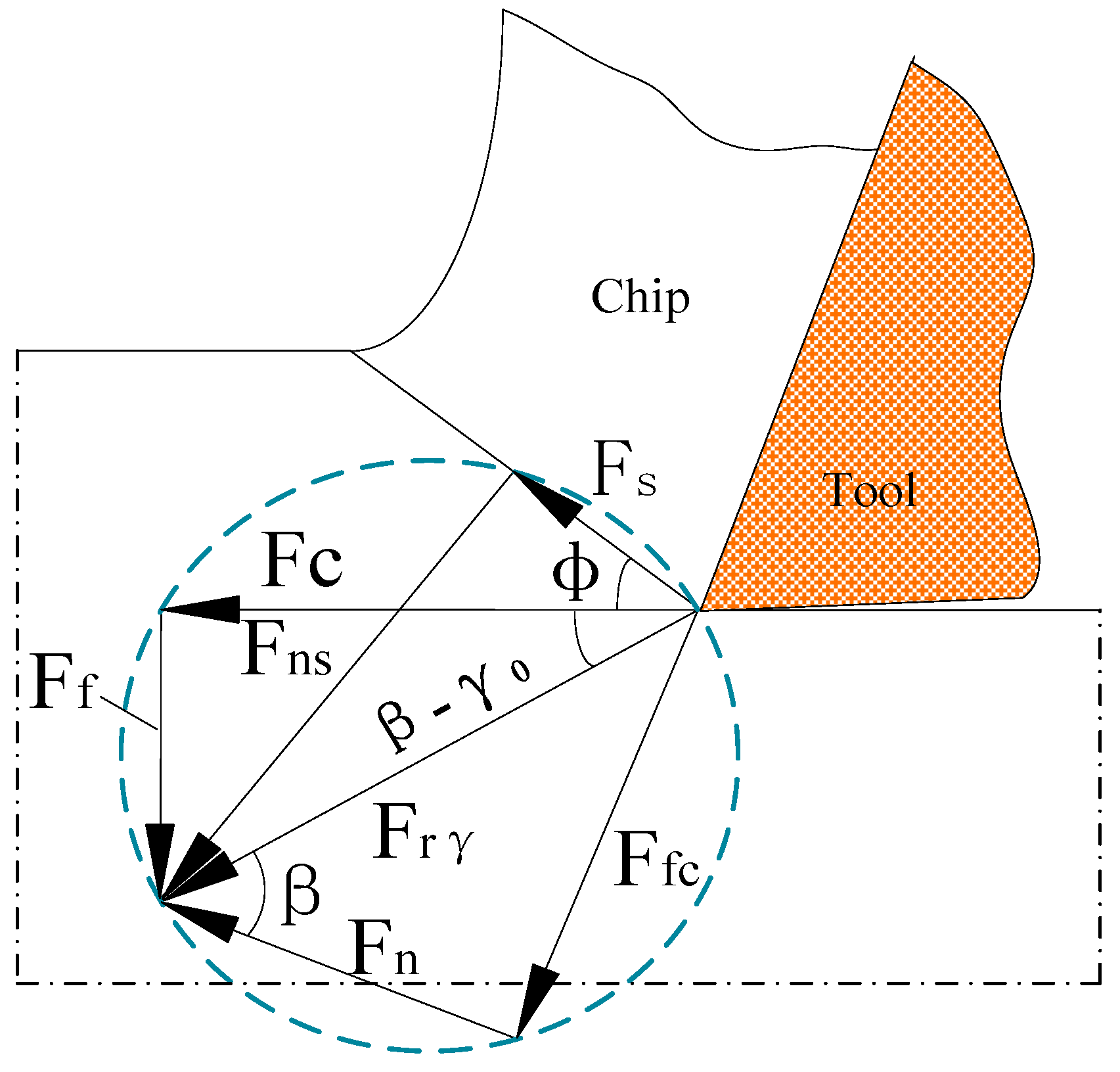
Figure 1. The relationship between tool angle and cutting force.
Coatings 15 01115 g001
Figure 2. WC carbide cutting tool.
Coatings 15 01115 g002
Figure 3. Tool cutting simulation.
Coatings 15 01115 g003
Figure 4. Cutting force distribution.
Coatings 15 01115 g004
Figure 5. Cutting temperature distribution.
Coatings 15 01115 g005
Figure 6. (a) Variation in cutting force with inclination angle. (b) Variation in cutting force with main cutting edge angle. (c) Variation in cutting force with rake angle.
Coatings 15 01115 g006
Figure 7. (a) Variation in temperature with inclination angle. (b) Variation in temperature with main cutting edge angle. (c) Variation in temperature with rake angle.
Coatings 15 01115 g007
Figure 8. Main cutting force main effect diagram.
Coatings 15 01115 g008
Figure 9. (a) Variation in main cutting force with cutting speed. (b) Variation in temperature with cutting speed. (c) Variation in main cutting force with feed rate. (d) Variation in temperature with feed rate. (e) Variation in main cutting force with cutting depth. (f) Variation in temperature with cutting depth.
Coatings 15 01115 g009
Figure 10. (a) Experimental platform. (b) Data acquisition device.
Coatings 15 01115 g010
Figure 11. (a) Simulated versus experimental results at different cutting speeds. (b) Simulated versus experimental results at different feed rates. (c) Simulated versus experimental results at different depths of cut.
Coatings 15 01115 g011
Figure 12. (a) Bruker optical profilometer. (b) Surface measurement results.
Coatings 15 01115 g012
Figure 13. (a) Effect of cutting speed on surface roughness. (b) Effect of feed rate on surface roughness. (c) Effect of cutting depth on surface roughness.
Coatings 15 01115 g013
Table 1. Chemical composition of AISI 4130 material.
Chemical CompositionCCrMoMnSiNi
Mass fraction ratio (wt%)0.28–0.330.80–1.10.15–0.250.4–0.60.15–0.35≤0.25
Table 2. Physical properties of cutting tools and workpiece materials.
Performance ParametersDensity
(g/cm3)
Modulus of Elasticity (GPa)Tensile Strength (MPa)Thermal Conductivity
(W/m·K)
Poisson
Ratio
Hardness
AISI 41307.85190–210≥93042.70.28≤229 HB
Tool (WC)13.66502000720.2389–94 HRA
Table 3. Tool geometric angle parameter setting.
Tool AngleAngle Change (°)
Inclination angle−5, −2, 2, 5
Main cutting edge angle93, 95, 97, 99
Rake angle3, 5, 7, 9
Table 4. Main cutting force and cutting temperature vary with tool angle.
Simulated ExperimentInclination Angle
λs/(°)
Main Cutting
Edge Angle
κr/(°)
Rake Angle
γ0/(°)
Principal Cutting Force
Fc/(N)
Cutting Temperature
t/(°C)
1−59551617.61700.1
2−29551619.23714.71
329551642.8807.89
459551657.05750.03
5−59351668.06685.61
6−59551617.61700.1
7−59751642.82711.35
8−59951639.63721.45
9−59531672.65712.81
10−59551617.61700.1
11−59571576.96707.44
12−59591571.94692.25
Table 5. Orthogonal experiment on cutting parameters for cemented carbide tools.
Simulated ExperimentInclination Angle
λs/(°)
Main Cutting
Edge Angle
κr/(°)
Rake Angle
γ0/(°)
Principal
Cutting Force
Fc/(N)
1−59331539.09
2−59551598.69
3−59771619.71
4−59991776.11
5−29351520.22
6−29571610.11
7−29791631.84
8−29931670.43
929371473.72
1029591564.96
1129751445.3
1229931311.23
1359391679.73
1459531449.03
1559751489.33
1659971432.93
Table 6. Extreme difference data on the effect of geometric angles on the main cutting force.
Analysis DataInclination Angle λs/(°)Main Cutting Edge Angle κr/(°)Rake Angle γ0/(°)
ABC
M11610.1731556.3451540.66
M21609.5231561.5981503.23
M31481.3081556.9131533.648
M41527.0131553.171650.478
R128.8658.4275147.2475
Primary–Secondary FactorsC-A-B
Best levelC2A3B4
Table 7. Single-factor cutting simulation experimental plan.
Simulation
Experiments
Cutting Speed
vc/(m/min)
Feed Rate
f/(mm/r)
Cutting Depth
ap/(mm)
1900.151.5
21100.151.5
31300.151.5
41500.151.5
51300.111.5
61300.131.5
71300.151.5
81300.171.5
91300.151.1
101300.151.3
111300.151.5
121300.151.7
Table 8. Simulated values and measured values of cutting experiments under different cutting conditions.
NumberVariation in Cutting
Parameters
Simulation
Fc/(N)
Actual Measurement Fc/(N)
1cutting speed
vc/(m/min)
901885.481686
21101776.391580
31301812.031615
41501643.771463
5feed rate f/(mm/r)0.111616.681402
60.131672.331469
70.151812.031619
80.171878.271677
9cutting depth
ap/(mm)
1.11656.021412
101.31785.231524
111.51812.031689
121.71930.041753
Table 9. Quantitative validation results for each cutting parameter.
Evaluation IndicatorCutting Speed
vc/(m/min)
Feed Rate f/(mm/r)Cutting Depth
ap/(mm)
RMSE193.56203.22208.73
MAPE12.20%13.27%12.95%
Disclaimer/Publisher’s Note: The statements, opinions and data contained in all publications are solely those of the individual author(s) and contributor(s) and not of MDPI and/or the editor(s). MDPI and/or the editor(s) disclaim responsibility for any injury to people or property resulting from any ideas, methods, instructions or products referred to in the content.