Article

Comparison of the Erosive Wear Resistance of Ductile Cast Iron Following Laser Surface Melting and Alloying

by
Jacek Górka
,
Aleksandra Lont
*,
Damian Janicki
,
Tomasz Poloczek
and
Agnieszka Rzeźnikiewicz
Welding Department, Faculty of Mechanical Engineering, Silesian University of Technology, Konarskiego Street 18A, 44-100 Gliwice, Poland
*
Author to whom correspondence should be addressed.
Coatings 2024, 14(5), 646; https://doi.org/10.3390/coatings14050646
Submission received: 15 April 2024 / Revised: 15 May 2024 / Accepted: 17 May 2024 / Published: 20 May 2024
(This article belongs to the Special Issue Laser-Assisted Coating Techniques and Surface Modifications)

Abstract

:
This article presents research results on the influence of the laser surface melting and alloying processes on the erosive wear resistance of ductile cast iron. For the research, an EN-GJS 350-22 ductile cast iron surface was laser-melted and laser-alloyed with titanium powder in an argon and nitrogen atmosphere. Solid-particle erosion tests were carried out on the laser-melted and -alloyed surface layers and the base material according to the ASTM G76-04 standard with 30° and 90° impingement angles. The erosive wear resistance results were correlated with Vickers hardness and microstructural test results with the use of SEM (scanning electron microscopy), TEM (transmission electron microscopy), EDS (energy dispersive spectroscopy), and XRD (X-ray diffraction). The mechanisms of erosive wear were also analyzed for the laser-treated surface layers and the base material. The research showed that the laser melting and alloying processes with titanium powder had a positive effect on the hardness and erosive wear resistance of the ductile cast iron surface due to microstructure modification. Moreover, despite the lower hardness of the laser-alloyed surface layers, their composite microstructure had a positive impact on the erosive wear resistance in comparison to the laser-melted surface layers.

1. Introduction

The ductile cast irons (DCIs) are alloys commonly used for machine parts due to their high mechanical and fatigue strengths and plastic properties. DCIs also show a low stress concentration tendency, vibration-damping abilities, and good casting properties and machinability, which makes them relatively cheap and easy to form, even into complex shapes. The disadvantage that limits the use of DCIs in some applications is their insufficient hardness and wear resistance [1]. The degradation of materials due to wear mechanisms is a serious problem for many applications in industry. In response to this problem, and the need for wear-resistant materials with high strength, plastic, and fatigue properties, the various surface treatment technologies are constantly improved to meet the demands of industry [2,3,4,5]. Among the many surface treatment technologies, laser surface treatment provides many possibilities and potential applications for a wide range of materials. The high power density of the laser beam results in a low heat impact on the processed material, and low deformation and stress level, and enables precise treatment of small areas. High heating and cooling rates result in the formation of fine-grained structures with unique properties [6,7]. In the case of DCIs, in order to improve their surface hardness and wear resistance while maintaining the beneficial properties of the core, surface treatment technologies can be used, including laser surface treatment. For DCIs, the main laser surface treatments used are laser transformation hardening (LTH) [8,9], laser surface melting (LSM) [10,11], laser surface alloying (LSA) [12,13,14], and laser cladding (LC) [15,16,17,18].
It was previously reported that during the LSM process of DCI, a thin surface layer of the material is melted and the graphite precipitate dissolves in the liquid metal causing its enrichment with carbon. After passing the laser beam, dynamic cooling and crystallization of the metal occurs, resulting in the formation of a fine-grained, dendritic structure of the surface layer. In the melted zone, as a result of the high cooling rate, carbon precipitates as cementite, causing an increase in the hardness in comparison to the base material [19]. The structural modification obtained in the laser-melted surface layer of DCIs results in wear resistance improvement in comparison to the base material [20,21,22].
LSA provides much wider possibilities of shaping the structure and properties of the DCI surface layer in comparison to LSM by the addition of alloying elements or reinforcing particles [23,24,25]. The LSA process also enables the formation of metal–matrix composite (MMC) surface layers, which are commonly used in industry for machine parts exposed to wear in order to extend their service life, and therefore, reduce operating costs [26]. It was previously proven that due to the high carbon content in the liquid metal and the low Gibbs free energy for the formation of the TiC phase, with the addition of titanium powder in the LSA process of DCI, an in situ MMC structure can be formed in the surface layer. Selecting the proper process parameters enables the formation of the homogeneous MMC structure and enables control of the fraction, size, and morphology of titanium carbides. As shown by research conducted on this topic, such structural modifications result in increased hardness and wear resistance in comparison to the substrate material [27,28].
In previous work [29], an analysis of the influence of nitrogen in the LSA process of DCI with titanium powder was carried out. Due to the strong affinity of titanium to both carbon and nitrogen, the process led to titanium carbonitride precipitation in the surface layers. The current work aims to compare the influence of the LSM and LSA processes with titanium powder on the erosive wear resistance of the DCI surface. The influence of the process atmosphere (argon and nitrogen), structure (TiC/TiCN fraction, cementite fraction), and hardness on the erosive wear resistance are analyzed, as well as the erosion mechanisms.

2. Materials and Methods

For the research, ductile cast iron of grade EN-GJS-350-22 was selected as the substrate material. The chemical composition of the used DCI is presented in Table 1. The microstructure of the selected DCI is composed of about 20 vol.% spheroidal graphite precipitate in a ferritic matrix (Figure 1). Prior to the laser processing, the substrate surface was ground to an Ra of 0.5 µm and degreased with ethyl alcohol. For the LSA processes, 99.0% pure titanium powder (H.C. Starck Amperit 154) with 45–70 µm gradation was used, which was dried directly before the process in an oven at 50 °C for 30 min. As shielding and powder-transporting gases for the LSM and LSA processes, 99.999% pure nitrogen and argon were used.
The laser processing was carried out using a stand equipped with the high-power direct diode laser (HPDDL) Rofin Sinar DL020. The technical specifications of the laser are presented in Table 2. The stand was also equipped with a numerically controlled positioning system for the laser head and substrate material. The movement of the traverse was parallel to the short axis of the laser beam focus. For the powder feeding for the LSA process, a disk powder-feeding system with a vibrator was used. The titanium powder was fed directly into the area of laser beam impact at an angle of 45° to the substrate surface. The powder nozzle’s shape and size were adapted to the laser beam focus’s shape and size in order to ensure uniform powder injection (Figure 2). The rectangular laser beam spot, of size 1.5 × 6.6 mm and uniform density distribution along the focus axis, was focused on the substrate surface. Single-scan LSM and LSA processes were carried out without preheating. The flow rates and powder feed rates of the powder-transporting gases and shielding gases, and the laser beam power and speed were selected on the basis of preliminary tests. A list of the samples made for the research and the process parameters is presented in Table 3. The shielding gas flow rate for the LSM process was 20 L/min and for the LSA process 15 L/min. The powder-transporting gas flow rate for the LSA process was 3 L/min.
The macroscopic observations were carried out using an Olympus SZX9 optical microscope (Olympus, Tokyo, Japan) manufacturer, city, state (only for USA and Canada), country). Microstructural characterization was performed using a Phenom-World PRO scanning electron microscope (SEM, Thermo Fisher Scientific, Waltham, MA, USA) and FEI TITAN 80/300 transmission electron microscope (TEM, Scientific and Technical Instruments, Hillsboro, OR, USA) with energy dispersive spectroscopy analysis (EDS). The thin foil for TEM investigations was prepared using Xe-PFIB technology. Samples for the macro- and microscopic observations were etched in 4% Nital solution. The phase compositions of the processed surface layers were determined using X-ray diffraction (XRD) analysis with a PANalytical X’Pert PRO MPD diffractometer (Malvern Panalitycal, Malvern, UK) equipped with a PIXcel3D 1 × 1 detector using filtered radiation from a lamp with a cobalt anode. The average TiC(N) precipitate and cementite fractions were measured using the Image-Pro Plus software (version 4.5.0.29) on a total of 8 SEM images of nonetched LSA surface-layer cross-sections (4 near the surface and 4 near the fusion line).
The Vickers hardness was measured using a Wilson Wolpert 401 MVD tester (Wilson Instruments, Instron Company, Norwood, MA, USA) for each surface-layer cross-section with a load of 200 g and dwell time of 10 s. The hardness tests were performed in three measuring lines from the surface to the substrate with a 0.1 mm step (Figure 3).
The solid-particle erosion tests of the laser-processed layers and substrate material were performed on a test stand that met the requirements of the ASTM G76-04 standard [30]. Angular 50 μm Al2O3 was used as the erodent material in a stream of dry compressed air with a velocity of 70 m/s and a feed rate of 2 g/min. The erodent was injected onto the tested surface for 10 min through a 1.5 mm diameter and 50 mm long nozzle. The distance between the nozzle and the material’s surface was 10 mm. The solid-particle erosion tests were carried out using impingement angles of 30° and 90°. To determine average results (steady-state erosion rate and erosion value according to ASTM G76-04 [30]) for each surface layer and impingement angle, 3 tests were performed. The mass loss was obtained using a laboratory scale with 0.001 g accuracy. The tested surface layers and the substrate densities were determined using the Archimedes method. In order to determine the erosive wear mechanism, SEM microscopic observations of the crater surfaces were carried out.

3. Results and Discussion

The macrographs of the representative surface layers are shown in Figure 4. The SEM microstructures of the laser-treated surface layers are shown in Figure 5 and the microstructural parameters are presented in Table 4. The representative EDS maps of the laser-alloyed surface layers are shown in Figure 6. Figure 7 presents the EDS line-scan profile of the composition of the TiCN precipitate from the TEM. The XRD results are presented in Figure 8. In general, the mechanism of fluid flow during laser surface processing is a surface tension gradient (Marangoni convection) [31]. The shapes of the fusion zones of the laser-melted and -alloyed surface layers indicate that during those processes the surface tension was highest at the center of the molten pool and produced fluid flow inward along the molten pool surface. The laser surface melting processes in the argon and nitrogen atmospheres caused the graphite precipitate’s dissolution in the liquid metal pool, which resulted in carbon enrichment of the liquid metal. As a result of the fast cooling of the metal pool, during crystallization graphite did not precipitate. After the laser beam passing, due to the cooling by heat conduction to the base metal, the primary austenite dendrites grew from the fusion line, then the eutectic austenite and cementite precipitated in the interdendritic spaces. Then, due to the high cooling rate, the martensitic transformation occurred. The microscopic analysis did not show any influence of nitrogen compared to argon shielding on the microstructure or chemical and phase compositions of the LSM surface layers. The XRD analysis for both of the atmospheres used indicated the presence of α-Fe (martensite), γ-Fe (retained austenite), and Fe3C (cementite) in the structures. No significant differences in the fractions of these components were noted for the same LSM process parameters. For both atmospheres used, for samples laser-melted with a 2000 W laser beam power and speeds of 0.2 and 0.4 cm/min, the increased speed caused the cementite fraction to decrease (by 10.7 vol.% and 6.8 vol.% for the argon and nitrogen shields, respectively) and the retained austenite fraction to increase (by 19.3 wt.% and 22.0 wt.% for the argon and nitrogen shields, respectively), due to the cooling rates resulting from the process parameters.
The LSA process on the DCI’s surface caused in situ metal–matrix composite microstructure formation in the surface layers, in which the matrix was composed of primary austenite dendrites transformed to martensite and ledeburite in the interdendritic regions, which is similar to the LSM surface layers’ microstructure. Depending on the process parameters (mainly titanium powder feed rate) the cubic or dendritic phases precipitated from the liquid metal during crystallization. The EDS and XRD analyses proved that those precipitates were titanium carbides or titanium carbonitrides for the process being carried out in an argon or nitrogen shield, respectively. In general, the analyzed process parameters produced homogeneous in situ metal–matrix composite surface layers reinforced by 5.5–20.1 vol.% of TiC precipitate and 4.8–10.1 vol.% of TiCN precipitate for the argon and nitrogen shields, respectively. With a titanium content increase in the liquid metal pool, the TiC(N) precipitate fraction increased. In comparison to LSM processes, the cementite fractions are lower for LSA surface layers. The cementite fraction also decreased with titanium content increases. This is due to the order of phase formation during cooling of liquid metal in the Fe-Ti-C and Fe-Ti-C-N systems [32,33,34,35,36]. The lower Gibbs free energy for TiC and TiCN resulted in the formation of those phases from the liquid metal first during cooling. With the increase in the titanium content and simultaneous increase in the TiC(N) precipitate fraction, the carbon content in the remaining liquid decreased, which resulted in a lower cementite fraction in the matrix. The titanium content did not affect the retained austenite fraction.
The average Vickers hardness and solid-particle erosion test results are presented in Table 5. For all analyzed samples, the laser surface treatment process caused the average hardness to increase. In the case of the LSM process, the hardness increased by 524–639 HV0.2 and 587–618 HV0.2 for the argon and nitrogen shields, respectively, in comparison to the base metal. The LSA process resulted in hardness increases of 458–591 HV0.2 and 391–460 HV0.2 for the argon and nitrogen shields, respectively, in comparison to the base metal. The higher hardness results of the LSM surface layers in comparison to the LSA surface layers are affected by the higher fraction of cementite in the microstructure. In general, the cementite fraction influenced the hardness results the most for the laser-melted and -alloyed surfaces, regardless of the shielding gas used. The hardness measurements distribution profiles are presented in Figure 9. The LSM surface layers show highly consistent hardness in the melted zone, due to the high homogeneity of the microstructure. In the case of the LSA surface layers, due to the composite microstructure, a slightly wider range of hardness results was obtained in the alloyed zone. For all laser-treated surface layers, the hardness gradually decreased in the heat-affected zone, reaching values typical for the substrate material.
The solid-particle erosion test results show that the laser surface melting and alloying processes carried out to modify the ductile cast iron surface had a positive effect on improving its erosion wear resistance. The average erosion values of all the tested surface layers and the substrate material are higher for the impingement angle of 30° than for 90°. Such results are typical for plastic materials [37]. In the case of the LSM surface layers, the average erosion values and rates for all samples are similar, so the shielding gas did not influence the erosion wear resistance of the layers. Generally, the laser surface melting process caused the average erosion values to decrease for the impingement angle of 30° in comparison to the base material, by up to 24% and 30% for the argon and nitrogen shields, respectively. For the 90° angle, the erosion rates and values are similar for LSM surface layers and the substrate. In the case of the LSA process, for both the tested impingement angles, the average erosion value decreased in comparison to the substrate material. In the case of the 30° impingement angle, the erosion values decreased by up to 48% and 40% for the argon and nitrogen shields, respectively. For the 90° impingement angle, the average erosion values decreased by up to 26% and 23% for the argon and nitrogen shields, respectively. The results show that the shielding gas and, consequently, the precipitate’s chemical composition did not significantly influence the erosion wear resistance. Despite the lower average hardness of the LSA surface layers in comparison to LSM, the erosion test results showed better resistance of the alloyed layers. This result is related to the composite microstructure of the LSA surface layers—the presence of an evenly dispersed TiC(N) precipitate in the structure.
The SEM images of the surfaces after the solid-particle erosion tests are presented in Figure 10. The observations allow us to specify the erosion mechanisms of the tested surface layers and the substrate material. In the case of the ductile cast iron surface, during erosion, plastic deformation occurred and scars, grooves, and craters can be observed on the surface for both the tested impingement angles. Additionally, embedded erodent particles can be observed on the surface due to the low hardness of the material. The erosion mechanism of the used ductile cast iron is therefore ductile. On the LSM surface layers, plastic deformation can be observed as a result of erosion, therefore, the erosion mechanism is also ductile for these layers. In this case, no embedded erodent particles were observed, which is due to the higher hardness of the surface. For the LSA surface layers, the erosion behavior is more complex due to the composite microstructure. In the matrix, plastic deformation occurred during erosion similar to in the LSM layers. However, for the in situ-formed TiC(N) precipitate, cracks were observed, indicating a brittle erosion mechanism. Additionally, on the composite layer’s surfaces, voids were also observed on the surfaces, from which the precipitate was torn out during erosion.

4. Conclusions

Based on the analysis of the achieved research results, the following conclusions have been reached:
  • The laser surface melting processes of the EN-GJS-350-22 ductile cast iron in argon and nitrogen shields caused modification of the microstructure of the surface layers that consist of primary austenite dendrites, partly after martensitic transformation, and eutectic austenite and ledeburite in the interdendritic spaces. The use of the nitrogen shield did not affect the microstructure or nitrogen’s presence in the surface layer’s chemical composition.
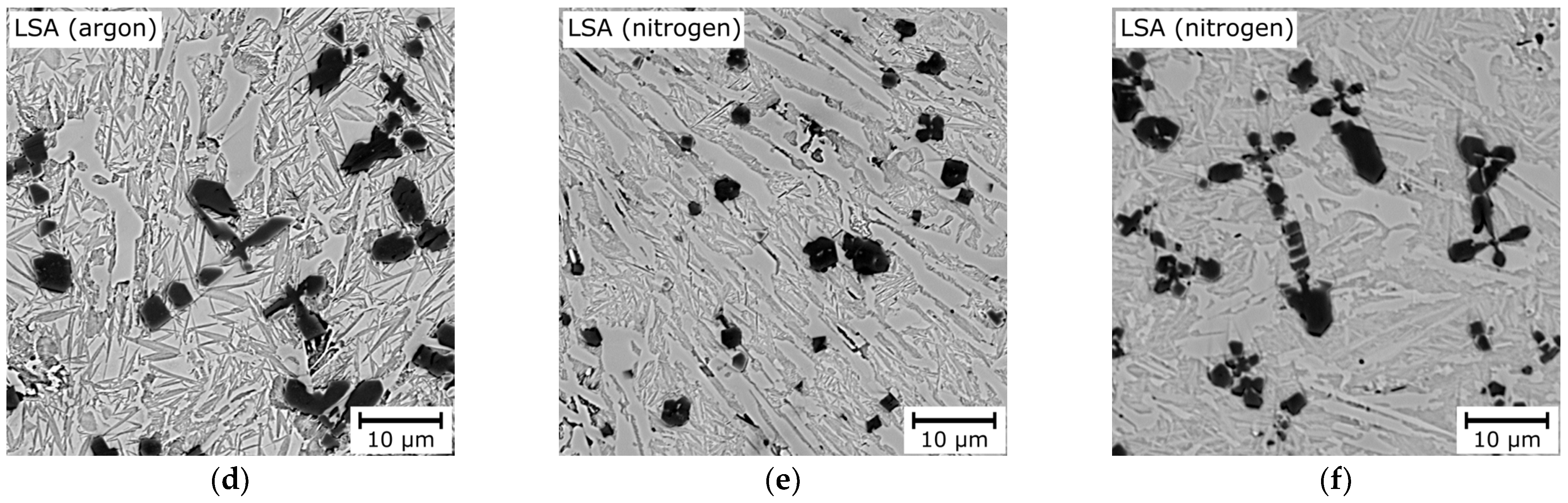
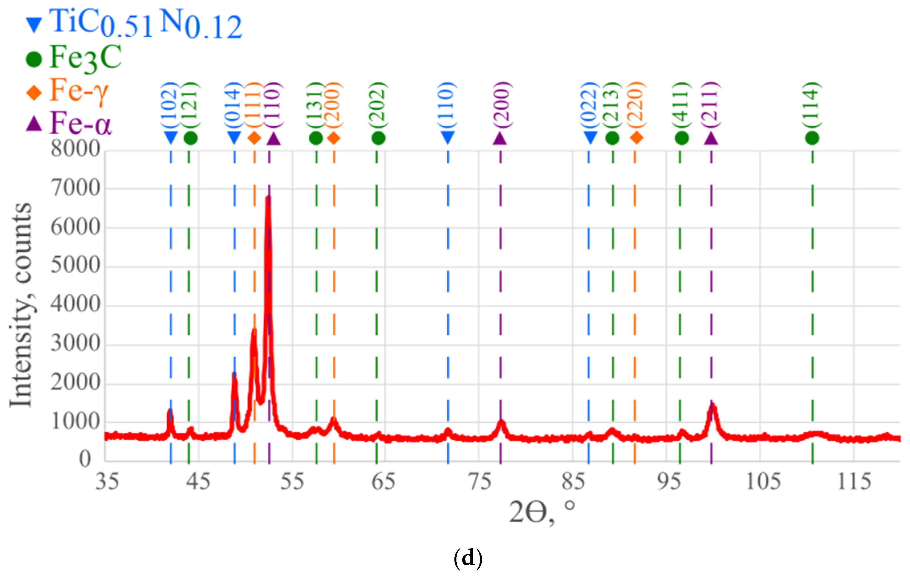
  • The laser surface alloying process of the EN-GJS-350-22 ductile cast iron with titanium allowed the formation of homogeneous in situ metal–matrix composite surface layers. Depending on the shielding gas (argon or nitrogen), cubic or dendritic TiC/TiCN particles precipitated from the liquid metal. The matrix microstructure consisted of primary austenite dendrites, partly after martensitic transformation, and ledeburite in the interdendritic spaces.
  • By the selection of the LSA process parameters it is possible to shape the structure of the surface layers, in particular the titanium concentration, precipitate’s morphology, fraction, and chemical composition. The parameters selected for the research allowed surface layers reinforced with 5.5–20.2 vol.% of TiC and 4.8–10.1 vol.% of TiCN to be produced.
  • The modification of the microstructure by the laser surface melting of ductile cast iron resulted in the average Vickers hardness increasing by a maximum of 370% and 362% for the argon and nitrogen shields, respectively. The laser-alloyed surface layers showed average Vickers hardness increases of a maximum of 297% and 295% for the argon and nitrogen shields, respectively.
  • The laser surface melting and alloying processes caused an erosion resistance increase in the ductile cast iron. The erosion values of the LSM and LSA surface layers for a 30° impingement angle decreased by a maximum of 30% and 48%, respectively. In the case of the 90° impingement angle, the LSM layers showed similar erosion values, and for LSA layers, the erosion values decreased by up to 26% in comparison to the substrate material. The composite microstructure of the LSA surface layers caused a higher increase in the erosion resistance in comparison to LSM layers in addition to the lower hardness.
  • The erosion mechanism of the substrate material and laser-melted surface layers is ductile. For the laser-alloyed surface layers, the erosion mechanism is more complex, being ductile for the matrix material and brittle for the TiC(N) precipitate.

Author Contributions

Conceptualization, J.G., A.L. and D.J.; methodology, D.J., A.L. and T.P.; software, A.L. and A.R.; validation, J.G., A.L., D.J., T.P. and A.R.; formal analysis J.G., A.L., D.J., T.P. and A.R.; investigation, A.L. and D.J.; resources, J.G. and T.P.; data curation, A.L. and A.R.; writing—original draft preparation, A.L.; writing—review and editing, J.G. and D.J. All authors have read and agreed to the published version of the manuscript.

Funding

This research received no external funding.

Institutional Review Board Statement

Not applicable.

Informed Consent Statement

Not applicable.

Data Availability Statement

The original contributions presented in the study are included in the article, further inquiries can be directed to the corresponding author.

Conflicts of Interest

The authors declare no conflicts of interest.

References

  1. Elliot, R. Cast Iron Technology, 1st ed.; Butterworth & Co.: London, UK, 1988; pp. 13–20. [Google Scholar]
  2. Czupryński, A.; Żuk, M. Matrix Composite Coatings Deposited on AISI 4715 Steel by Powder Plasma-Transferred Arc Welding. Part 3. Comparison of the Brittle Fracture Resistance of Wear-Resistant Composite Layers Surfaced Using the PPTAW Method. Materials 2021, 14, 6066. [Google Scholar] [CrossRef] [PubMed]
  3. Poloczek, T.; Lont, A.; Górka, J. The Structure and Properties of Laser-Cladded Inconel 625/TiC Composite Coatings. Materials 2023, 16, 1265. [Google Scholar] [CrossRef] [PubMed]
  4. Krella, A. Resistance of PVD Coatings to Erosive and Wear Processes: A Review. Coatings 2020, 10, 921. [Google Scholar] [CrossRef]
  5. Jonda, E.; Szala, M.; Sroka, M.; Łatka, L.; Walczak, M. Investigations of cavitation erosion and wear resistance of cermet coatings manufactured by HVOF spraying. Appl. Surf. Sci. 2023, 608, 155071. [Google Scholar] [CrossRef]
  6. Cui, C.; Wu, M.; Miao, X.; Gong, Y.; Zhao, Z. The effect of laser energy density on the geometric characteristics, microstructure and corrosion resistance of Co-based coatings by laser cladding. JMR&T 2021, 15, 2405–2418. [Google Scholar]
  7. Anas, A.S.; Avanish, K.D. Recent trends in laser cladding and surface alloying. Opt. Laser Technol. 2021, 134, 106619. [Google Scholar]
  8. Malek Ghaini, F.; Ameri, M.H.; Torkamany, M.J. Surface transformation hardening of ductile cast iron by a 600w fiber laser. Optik 2020, 203, 163758. [Google Scholar] [CrossRef]
  9. Ion, J.C. Laser Transformation Hardening. Mater. Surf. Eng. 2002, 18, 14–31. [Google Scholar] [CrossRef]
  10. Kotarska, A.; Janicki, D.; Górka, J.; Poloczek, T. Solid particle erosion of laser surface melted ductile cast iron. Arch. Foundry Eng. 2020, 20, 105–111. [Google Scholar] [CrossRef]
  11. Murakami, R.; Narita, I.; Miyahara, H. Surface microstructure and properties of nodular cast iron rapidly solidified by laser surface melting. Mater. Trans. 2018, 59, 1465–1470. [Google Scholar] [CrossRef]
  12. Jeyaprakash, N.; Yang, C.H.; Duraiselvam, M.; Prabu, G. Microstructure and tribological evolution during laser alloying WC-12%Co and Cr3C2-25%NiCr powders on nodular iron surface. Results Phys. 2019, 12, 1610–1620. [Google Scholar] [CrossRef]
  13. Yan, H.; Wang, A.; Xiong, Z.; Xu, K.; Huang, Z. Microstructure and wear resistance of composite layers on a ductile iron with multicarbide by laser surface alloying. Appl. Surf. Sci. 2010, 256, 7001–7009. [Google Scholar] [CrossRef]
  14. Paczkowska, M. The Comparison of the Effects of Nodular Cast Iron Laser Alloying with Selected Substances. Materials 2022, 15, 7561. [Google Scholar] [CrossRef] [PubMed]
  15. Sun, F.; Cai, K.; Li, X.; Pang, M. Research on Laser Cladding Co-Based Alloy on the Surface of Vermicular Graphite Cast Iron. Coatings 2021, 11, 1241. [Google Scholar] [CrossRef]
  16. Li, Y.; Dong, S.; Yan, S.; Liu, X.; He, P.; Xu, B. Microstructure evolution during laser cladding Fe-Cr alloy coatings on ductile cast iron. Opt. Laser Technol. 2018, 108, 255–264. [Google Scholar] [CrossRef]
  17. Arias-Gonzalez, F.; del Val, J.; Comesana, R.; Penide, J.; Lusquinos, F.; Quintero, F.; Riveiro, A.; Boutinguiza, M.; Pou, J. Fiber laser cladding of nickel-based alloy on cast iron. Appl. Surf. Sci. 2016, 374, 197–205. [Google Scholar] [CrossRef]
  18. Li, Y.; Dong, S.; He, P.; Yan, S.; Li, E.; Liu, X.; Xu, B. Microstructure characteristics and mechanical properties of new-type FeNiCr laser cladding alloy coating on nodular cast iron. J. Mater. Process. Technol. 2019, 269, 163–171. [Google Scholar] [CrossRef]
  19. Grum, J.; Sturm, R. Microstructure analysis of nodular iron 400-12 after laser surface melt hardening. Mater. Charact. 1996, 37, 81–88. [Google Scholar] [CrossRef]
  20. Yang, H.; Zhou, T.; Wang, Q.; Zhou, H. Effects of Laser Melting Distribution on Wear Resistance and Fatigue Resistance of Gray Cast Iron. Metals 2020, 10, 1257. [Google Scholar] [CrossRef]
  21. Pagano, N.; Angelini, V.; Ceschini, L.; Campana, G. Laser remelting for enhancing tribological performances of a ductile iron. Proc. CIRP 2016, 41, 987–991. [Google Scholar] [CrossRef]
  22. Alabeedi, K.F.; Abboud, J.H.; Benyounis, K.Y. Microstructure and erosion resistance enhancement of nodular cast iron by laser melting. Wear 2009, 266, 925–933. [Google Scholar] [CrossRef]
  23. Paczkowska, M.; Makuch, N.; Kulka, M. The influence of various cooling rates during laser alloying on nodular iron surface layer. Opt. Laser Technol. 2018, 102, 60–67. [Google Scholar] [CrossRef]
  24. Chen, Z.; Meng, C.; Dong, J.; Zhou, T.; Tong, X.; Zhou, H. The comparative study of W/Cr addition in Fe-base by laser surface alloying on fatigue wear resistance of GCI. Surf. Coat. Technol. 2016, 286, 25–35. [Google Scholar] [CrossRef]
  25. Yilbas, B.S.; Akhtar, S.S.; Karatas, C.; Boran, K. Laser treatment of dual matrix cast iron with presence of WC particles at the surface: Influence of self-annealing on stress fields. Opt. Laser Technol. 2016, 76, 6–18. [Google Scholar] [CrossRef]
  26. Janicki, D. The friction and wear behaviour of in-situ titanium carbide reinforced composite layers manufactured on ductile cast iron by laser surface alloying. Surf. Coat. Technol. 2021, 406, 126634. [Google Scholar] [CrossRef]
  27. Kotarska, A. The Laser Alloying Process of Ductile Cast Iron Surface with Titanium. Metals 2021, 11, 282. [Google Scholar] [CrossRef]
  28. Janicki, D. Shaping the Structure and Properties of Surface Layers of Ductile Cast Iron by Laser Alloying, 1st ed.; Wydawnictwo Politechniki Śląskiej: Gliwice, Poland, 2018; p. 29. [Google Scholar]
  29. Lont, A.; Górka, J.; Janicki, D.; Matus, K. The Laser Alloying Process of Ductile Cast Iron Surface with Titanium Powder in Nitrogen Atmosphere. Coatings 2022, 12, 227. [Google Scholar] [CrossRef]
  30. ASTM G76-04; Standard Test Method for Conducting Erosion Tests by Solid Particle Impingement Using Gas Jets. ASTM International: West Conshohocken, PA, USA, 2004.
  31. Kundakcıoğlu, E.; Lazoglu, I.; Poyraz, Ö.; Yasa, E.; Cizicioğlu, N. Thermal and molten pool model on selective laser melting process of Inconel 625. Int. J. Adv. Manuf. Technol. 2018, 95, 3977–3984. [Google Scholar] [CrossRef]
  32. Frisk, K. A revised thermodynamic description of the Ti-C system. Calphad 2003, 27, 367–373. [Google Scholar] [CrossRef]
  33. Zhu, H.; Dong, K.; Wang, H.; Huang, J.; Li, J.; Xie, Z. Reaction mechanisms of the TiC/Fe composite fabricated by exothermic dispersion from Fe-Ti-C element system. Powder Technol. 2013, 246, 456–461. [Google Scholar] [CrossRef]
  34. Jonsson, S. Calculation of the Ti-C-N system. Z. Metallkde 1996, 87, 713–720. [Google Scholar] [CrossRef]
  35. Dumitrescu, L.F.S.; Hillert, M.; Sundman, B. A reassessment of Ti-C-N based on a critical review of available assessments of Ti-N and Ti-C. Z. Metallkde 1999, 90, 534–541. [Google Scholar] [CrossRef]
  36. Gorbachev, I.I.; Popov, V.V. Analysis of the solubility of carbides, nitrides and carbonitrides in steels using methods of computer thermodynamics: III. Solubility of carbides, nitrides and carbonitrides in the Fe-Ti-C, Fe-Ti-N and Fe-Ti-C-N systems. Phys. Met. Metallogr. 2009, 108, 484–495. [Google Scholar] [CrossRef]
  37. Stachowiak, G.W.; Batchelor, A.W. Engineering Tribology, 4th ed.; Butterworth-Heinemann: Oxford, UK, 2014; pp. 551–556. [Google Scholar]
Figure 1. The EN-GJS-350-22 ductile cast iron’s microstructure (optical microscope).
Coatings 14 00646 g001
Figure 2. Diagram showing the alignment of the powder injection nozzle relative to the laser beam spot [28].
Coatings 14 00646 g002
Figure 3. The Vickers hardness measurement point distribution on the cross-sections of laser-treated surface layers [29].
Coatings 14 00646 g003
Figure 4. The macrographs of representative surface layers: (a) A1, (b) N1, (c) TA3, and (d) TN2 [29]. Designations according to Table 3.
Coatings 14 00646 g004
Figure 5. The SEM microstructures of representative surface layers: (a) A1, (b) N1, (c) TA1, (d) TA3, (e) TN1, (f) and TN3. Designations according to Table 3.
Coatings 14 00646 g005aCoatings 14 00646 g005b
Figure 6. The EDS mapping of the composition of representative laser-alloyed surface layers: (a) TA2 and (b) TN2 [29]. Designations according to Table 3.
Coatings 14 00646 g006
Figure 7. (a) The TEM EDS line-scan profile of the composition of TiCN precipitate from the laser-alloyed surface layer in nitrogen shield; (b) the measuring line from A to B [29].
Coatings 14 00646 g007
Figure 8. The XRD results of representative surface layers: (a) A1, (b) N1, (c) TA2, and (d) TN2. Designations according to Table 3.
Coatings 14 00646 g008aCoatings 14 00646 g008b
Figure 9. The hardness distribution in the representative surface layers from the surface towards the fusion line; designations according to Table 3.
Coatings 14 00646 g009
Figure 10. The SEM images of representative surface layers after solid-particle erosion tests: (a) impingement angle 30° [29], EN-GJS-350-22; (b) impingement angle 90°, EN-GJS-350-22; (c) impingement angle 30°, A3; (d) impingement angle 90°, N1; (e) impingement angle 30°, TA2; (f) impingement angle 90°, TN2; designations according to Table 3.
Coatings 14 00646 g010
Table 1. Chemical composition of EN-GJS-350-22 ductile cast iron.
Chemical Composition, wt.%
CSiMnPSCuTiMgCr
3.662.710.5270.0420.0010.0680.0320.0120.124
Table 2. Technical specifications of the Rofin Sinar DL020 HPDDL.
Wavelength of the Laser Radiation, nm808–940 ± 5
Range of Laser Power, W100–2000
Focal Length, mm82
Laser Beam Spot Size, mm1.5 × 6.6
Range of Laser Power Intensity, W/mm210.1–202.0
Table 3. The laser surface treatment process parameters.
DesignationProcessLaser Beam Power, WTraverse Speed, m/minShielding GasPowder-Transporting GasPowder Feed Rate, mg/mm
A1LSM20000.2argon--
A2LSM20000.4argon--
A3LSM15000.075argon--
N1LSM20000.2nitrogen--
N2LSM20000.4nitrogen--
N3LSM15000.075nitrogen--
TA1LSA20000.075argonargon4
TA2LSA20000.075argonargon8
TA3LSA20000.075argonargon12
TA4LSA20000.075argonargon16
TN1LSA17500.075nitrogennitrogen5.33
TN2LSA20000.075nitrogennitrogen4
TN3LSA20000.075nitrogennitrogen5.33
Table 4. The microstructural parameters of laser surface melted and alloyed ductile cast iron surface layers.
Designation (According to Table 3)Average Titanium Content, wt.%Average TiC(N) Fraction, vol.%Average Fe3C Fraction, vol.%Average Retained Austenite Fraction, wt.%Average Fe-α (Martensite) Fraction, wt.%
A1--55.7 ± 2.8610.9 ± 1.2333.6 ± 1.71
A2--45.0 ± 4.2430.2 ± 1.4119.7 ± 1.83
A3--53.8 ± 1.666.9 ± 0.9139.3 ± 1.75
N1--48.9 ± 1.1710.4 ± 0.9740.9 ± 1.62
N2--42.1 ± 1.8832.4 ± 1.3426.0 ± 0.94
N3--50.9 ± 1.198.2 ± 1.1541.1 ±1.14
TA13.2 ± 0.335.5 ± 1.1332.7 ± 4.3311.3 ± 0.8950.9 ± 2.05
TA25.5 ± 1.79.6 ± 2.2926.6 ± 2.0811.6 ± 1.1753.1 ± 1.62
TA39.1 ± 2.7814.1 ± 3.9113.9 ± 1.5210.1 ± 1.2162.0 ± 1.15
TA412.9 ± 1.7120.1 ± 2.294.7 ± 2.349.5 ± 1.1866.1 ± 1.39
TN13.6 ± 0.886.5 ± 1.7133.4 ± 2.2511.8 ± 1.3148.6 ± 1.81
TN23.2 ± 1.264.8 ± 1.5734.4 ± 5.7612.4 ± 1.0548.7 ± 1.37
TN35.8 ± 1.3510.1 ± 2.2327.1 ± 3.9313.3 ± 0.8849.5 ± 1.42
Table 5. The hardness and solid-particle erosion test results.
Designation (According to Table 3)Average Vickers Hardness, HV0.2Average Erosion Value, mm3/gAverage Steady-State Erosion Rate, mg/min
30°90°30°90°
A1875 ± 19.60.047 ± 0.0040.038 ± 0.0060.69 ± 0.050.57 ± 0.1
A2843 ± 17.20.047 ± 0.0020.043 ± 0.0070.7 ± 0.030.64 ± 0.1
A3792 ± 21.70.050 ± 0.0030.039 ± 0.0020.73 ± 0.050.58 ± 0.04
N1854 ± 19.00.046 ± 0.0080.041 ± 0.0020.69 ± 0.110.61 ± 0.03
N2833 ± 57.30.043 ± 0.0090.048 ± 0.0040.63 ± 0.140.71 ± 0.06
N3832 ± 33.30.048 ± 0.0050.039 ± 0.0040.72 ± 0.070.57 ± 0.06
TA1695 ± 39.50.036 ± 0.0010.025 ± 0.0030.52 ± 0.020.37 ± 0.04
TA2702 ± 33.00.032 ± 0.0010.025 ± 0.0040.45 ± 0.020.36 ± 0.04
TA3694 ± 62.70.039 ± 0.0010.028 ± 0.0020.56 ± 0.020.39 ± 0.02
TA4701 ± 43.70.039 ± 0.0010.031 ± 0.0050.54 ± 0.010.43 ± 0.06
TN1663 ± 54.10.041 ± 0.0030.027 ± 0.0020.6 ± 0.050.39 ± 0.03
TN2696 ± 30.50.037 ± 0.0040.029 ± 0.0040.55 ± 0.040.43 ± 0.04
TN3627 ± 40.80.041 ± 0.0020.026 ± 0.0030.6 ± 0.030.38 ± 0.04
Substrate236 ± 36.40.0617 ± 0.00040.034 ± 0.00320.88 ± 0.010.48 ± 0.05
Disclaimer/Publisher’s Note: The statements, opinions and data contained in all publications are solely those of the individual author(s) and contributor(s) and not of MDPI and/or the editor(s). MDPI and/or the editor(s) disclaim responsibility for any injury to people or property resulting from any ideas, methods, instructions or products referred to in the content.

