Article

Preparation of n-Tetradecane Phase Change Microencapsulated Polyurethane Coating and Experiment on Anti-Icing Performance for Wind Turbine Blades

1
College of Engineering, Northeast Agriculture University, Harbin 150030, China
2
College of Arts and Sciences, Northeast Agriculture University, Harbin 150030, China
*
Authors to whom correspondence should be addressed.
Coatings 2024, 14(5), 645; https://doi.org/10.3390/coatings14050645
Submission received: 26 April 2024 / Revised: 14 May 2024 / Accepted: 17 May 2024 / Published: 19 May 2024

Abstract

:
Icing is a common physical phenomenon, and the icing of wind turbine blades can significantly affect the performance of wind turbines. Therefore, researching methods to prevent icing is of great significance, and the coating method of anti-icing is an effective way to delay icing, with advantages such as low energy consumption and easy implementation. In this study, using the coating method as the background, tetradecane phase change microcapsules were prepared, with a melting enthalpy of 90.8 J/g and a crystallization enthalpy of 96.3 J/g, exhibiting good coverage and energy storage efficiency. After mixing tetradecane phase change microcapsules (PCMS) with polyurethane coating (PUR) and coating them on wind turbine blades, after a 5 min icing wind tunnel test, the coating could significantly delay the icing on the blade surface, with the highest anti-icing rate reaching 60.41%. This indicates that the coating has a good anti-icing effect and provides basic research data for exploring new anti-icing methods.

1. Introduction

With the increasing depletion of fossil fuels, the demand for renewable energy sources continues to rise globally [1,2]. Due to its widespread distribution, vast development potential, and environmental friendliness, wind energy has become a popular choice for renewable energy [3,4,5]. However, the icing of wind turbine blades in cold regions can affect their operation and even lead to accidents [6,7]. When icing on the blades exceeds a certain limit, wind turbines must be shut down to prevent significant impacts on the power grid [8,9,10]. Therefore, researching methods to prevent icing on wind turbine blades is an important research direction.
Currently, there are various methods for preventing icing, among which coating methods have attracted considerable attention. Conductive coatings are special coatings that possess electrical conductivity. Typically composed of conductive materials such as metals or carbon nanotubes, they are applied to the surface of substrates. When electrified, conductive coatings can conduct electricity and have the ability to convert electrical energy into thermal energy. This allows conductive coatings to play a significant role in applications such as anti-icing, heating, or sensing. Lopera-Valle et al. [11] utilized flame spraying to deposit nickel–chromium–aluminum–yttrium (NiCrAlY) coatings on fiber-reinforced polymer composite materials, enabling them to act as heating elements for de-icing through Joule heating when electrically powered. They further developed heat transfer models to predict heating and melting times, considering the coating as an interface heat source, and applied orthogonal expansion techniques and the method of separation of variables to determine temperatures in solids and melting of ice. Golewski et al. [12] investigated the effects of applying new technology to produce various coatings on carbon fiber-reinforced polymer (CFRP) substrates, evaluating their performance through flame exposure and solid particle erosion tests. The results indicated that the quartz sand coating demonstrated significant effectiveness in surface protection and enhancing tensile strength. Liu et al. [13] prepared ice-phobic coatings with photothermal and anticorrosive properties via surface-modified pyrolysis and a hydrothermal reaction using rice straw biogas residue as raw material. The erosion of KOH and surface modification of MoS2 made the material structure rough, and the high-temperature pyrolysis and hydrothermal reaction facilitated dehydrogenation and decarboxylation reactions, reduced the number of oxygen-containing functional groups, and lowered the surface energy of the material. The icing wind tunnel test results showed that the icing area and mass were reduced by 10.54% and 30.08%, respectively, at a wind speed of 10 m s−1 and a temperature of −10 °C. The icing area and mass were reduced by 10.54% and 30.08%, respectively. The photothermal performance test showed that the MoS2-loaded material has good light absorption performance, and the coating can be rapidly warmed up to 58.3 °C under xenon lamp irradiation with photothermal cycling stability. Wei et al. [14], for the development of embedded de-icing elements in polymer matrix composites, prepared nickel–chromium–aluminum–yttrium (NiCrAlY) coatings on fiber-reinforced polymer composite (FRPC) sheets using a flame spraying technique. An electric current was supplied to the metal alloy coating by means of Joule heating (or resistance heating) to generate energy and allow the coating to act as a heating element for the FRPC structure. De-icing tests were conducted at ambient temperatures of −5 °C, −15 °C, and −25 °C, with liquid water sprayed on the samples. A heat transfer model was developed for the heating and melting time of ice during the de-icing process of flame-sprayed coatings. The model is based on the separated variable method for solving the finite-length-scale melting problem and the Stefan problem for a semi-infinite medium, and a coating of about 100 μm thickness can effectively melt the ice accumulation on the polymer composite structure at low temperatures. The agreement between the computational results of the finite-length-scale model and the experimental data indicates that the heat conduction model based on the method of separated variables can be applied to the free boundary problem to predict the phase transition phenomena induced by thermal spray coatings. Zhuang et al. [15] present the results of laboratory tests on a carbon fiber-reinforced polymer (CFRP) composite with a single-sided protective coating. The protective coating consisted of five different powders (Al2O3, aluminum, quartz sand, crystalline silica, and copper) laminated with a single process during the curing of the prepreg substrate to the epoxy resin matrix. The specimens were subjected to flame exposure and solid particle erosion tests followed by uniaxial tensile tests. A digital image correlation (DIC) system was used to observe the damage location and the deformation of the specimens. All coatings subjected to solid particle erosion allowed for an increase in tensile damage force ranging from 5% to 31% compared to reference samples made of pure CFRP. When exposed to flame, only three of the five tested materials (Al2O3, aluminum, and quartz sand) could be used to protect the surface, which resulted in an increase in tensile breaking force of 5.6%. Piscitelli et al. [16] investigated the wettability of a newly developed superhydrophobic coating, which was applied as a general aviation coating using a layer-by-layer approach, and which can be used as a passive anti-icing system for aerospace applications. It was found that the wettability of uncoated samples decreases with increasing roughness to about 115° at Ra = 4 µm. The increase in water contact angle due to the increase in roughness can be attributed to the change in morphology. On the contrary, high contact angle values, i.e., about 158°, can be realized only after coating application. The application of the coating resulted in a reduction in SFE and WA of 99% and 94%, respectively. Sullivan et al. [17] proposed a hybrid anti-icing coating composed of thin-film electric heaters and superhydrophobic coatings, verifying its effectiveness in delaying droplet freezing through cold chamber experiments. Tong et al. [18] prepared a fluorine-free, low-cost superhydrophobic anti-icing coating for aerospace composites for morphological and compositional characterization and found it to have a low-surface-energy, multiscale layered structure. The coating has good water repellency and acid/alkaline drops, long durability, and excellent mechanical stability compared to recent reports. In addition, the coating can delay the ice increase by 120 min and exhibits low ice adhesion strength at 53.6 kPa, which is expected to enable anti-icing applications such as airfoil wind turbine blades. Qin et al. [19] used polytetrafluoroethylene (PTFE) coating to prepare nanoparticles for the anti-icing epoxy resin surface. The spray-coated PTFE particles can improve the anti-icing performance of the epoxy resin surface. The wetting behavior of the spray-coated surface, with a CA of 154° and ROA below 2°, was superior to that of unmodified aluminum, the epoxy resin surface, and the smooth PTFE surface, which had CAs of 81°, 59°, and 115°, respectively, in addition to the absence of effective ROA for the aluminum and epoxy resin surfaces, and 23.3° for smooth PTFE surfaces. The ice attachment strength of the PTFE-coated surfaces was 28 kPa, whereas it was 1120 kPa for polished aluminum, 161 kPa for smooth epoxy, and 137 kPa for smooth PTFE surfaces. This demonstrates the suitability of the coating method for large-area applications with high contact angles and low ice adhesion. Although significant progress has been made by the aforementioned researchers in coating anti-icing methods, further enhancement of the anti-icing effect of coatings is still needed.
Since phase change materials cannot be directly added to the surface of wind turbine blades, phase change microcapsules have become an excellent energy storage material [20]. The uniqueness of phase change microcapsules lies in encapsulating phase change materials in shells, which solves the problem of the possible leakage of phase change materials and successfully stores potential energy [21,22]. Phase change microcapsules can absorb or release heat in a specific temperature range, resulting in a phase change. Combining such microcapsules with a polyurethane coating delays the dramatic decrease in blade surface temperature, thereby improving anti-icing performance. When the temperature drops below a certain threshold, the microcapsules release heat to resist ice formation, effectively preventing icing.
Coating technology is a surface treatment that is used in a wide variety of industries to enhance the performance, appearance, and durability of materials. Common coating technologies include spraying, plating, thermal spraying, and dipping. Impregnation is a method [23,24] in which the material to be coated is immersed in the coating, absorbed, and then removed and dried. Due to its ease of operation, wide range of applications, uniformity of coating, and good adhesion, the dipping technique was chosen as the method for subsequent experiments in this study.
Interfacial polymerization [25,26] is a suitable method for the preparation of phase change microcapsules, in which core materials and oil-containing monomers are added to an aqueous phase, along with hydrophilic monomers and emulsifiers, and subsequently polymerized to form phase change microcapsules. Phase change microcapsules prepared via interfacial polymerization have been widely used because of their high encapsulation efficiency, good mechanical resistance, and simple preparation process [27,28].
Phase change microcapsules are capable of absorbing or releasing heat in a specific temperature range, leading to a phase change. The novelty of this study is that it is the first time that such microcapsules have been used on wind turbine blades in combination with a polyurethane coating, which can slow down the sharp drop in blade surface temperature and thus improve anti-icing performance.
In this study, phase change microcapsules were prepared and characterized via interfacial polymerization using tetradecane (C14) as the core material and isocyanate (IPDI) as the shell material, referring to the method of Zhu et al. [29]. These microcapsules were blended with polyurethane to form PCMS-PUR and applied to wind turbine blade surfaces, and the effectiveness of the coatings was verified with icing wind tunnel experiments. This study provides an important reference for the anti-icing technology of wind turbine blades.

2. Materials Preparation and Blade Model

The research roadmap is illustrated in Figure 1. Firstly, PCMS were prepared. Subsequently, PCMS-PUR was prepared by mixing PCMS with PUR. Finally, this coating was applied to wind turbine blades.

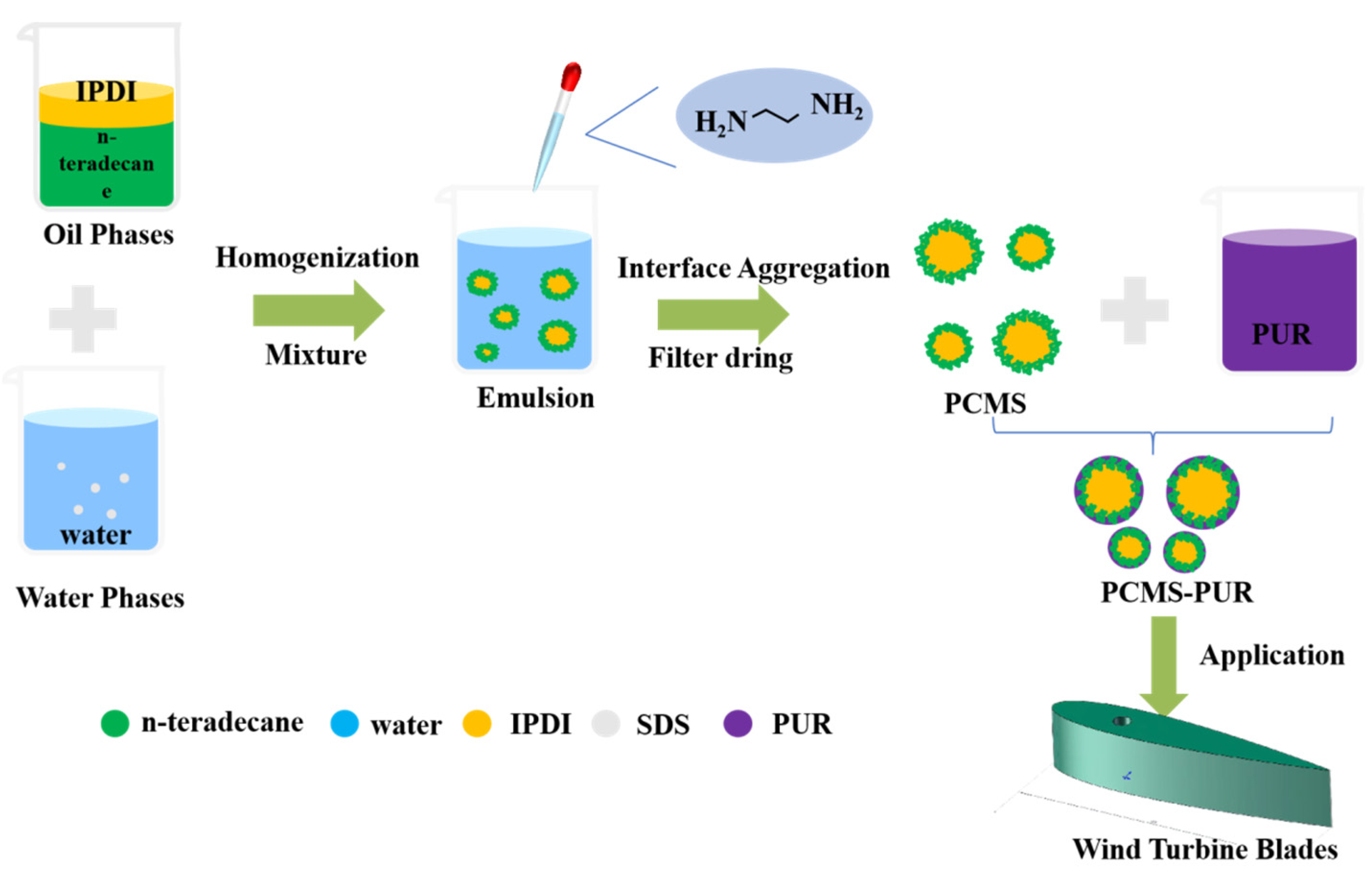
2.1. Preparation of Tetradecane Phase Change Microcapsule Polyurethane Coating

1.
Preparation of Oil Phase Materials;
  • Prepare a mixture of 9.9 g of petroleum ether and 0.1 g of dibutyltin dilaurate as the catalyst.
  • Weigh 3 g of C14 in a beaker and add 0.02 g of the catalyst and 2 g of IPDI dropwise.
  • Seal the beaker with plastic wrap, place it in a heat-collecting constant temperature magnetic stirrer, and heat and stir at 60 °C for 30 min to obtain an oil phase with a core–shell ratio of 6:4.
2.
Preparation of Water Phase Materials;
  • Place 0.05 g of sodium dodecyl sulfate (SDS) in a beaker.
  • Pour 50 g of deionized water into the beaker and place it in a 60 °C water bath.
  • Homogenize for 3 min at 10,000 rpm using a homogenizer to obtain the water phase.
3.
Preparation of PCMS;
  • Prepare an aqueous solution of ethylenediamine: add 1.275 g of ethylenediamine to 24.43 g of water.
  • Add the oil phase to the water phase and homogenize for 3 min at 60 °C and 10,000 rpm.
  • Transfer the mixture to a three-neck flask and react at 60 °C for 6 h.
  • During the intense reaction stage in the first 3 hours, add half of the ethylenediamine aqueous solution, and add the remaining half after 3 hours of reaction.
  • After 6 h of reaction, filter and dry the product using a filtration drying device to obtain PCMS powder.
4.
Preparation of PCMS-PUR.
  • Grind the dried PCMS-PUR into powder.
  • Mix the powder with PUR coating to obtain PCMS-PUR coating.
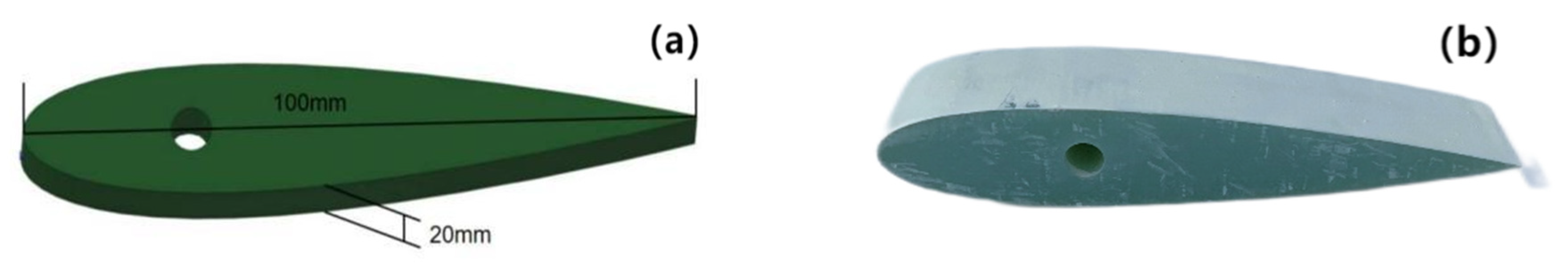
2.2. Blade Model

For this study, a NACA0018 blade made of fiberglass-reinforced plastic (FRP) was chosen as the base material. NACA0018 is a commonly used symmetric airfoil, especially in vertical-axis wind turbines. FRP is a widely used material in large wind turbines. The dimensions of the blade were determined via the icing wind tunnel used in this study, with a chord length of 100 mm and a span height of 20 mm. Refer to Figure 2 for a schematic representation.

3. Material Characterization and Analysis

3.1. Material Characterization

In this study, scanning electron microscopy (SEM, SU8010; Hitachi, Tokyo, Japan) was used for the morphological analysis of PCMS and PCMS-PUR. Differential scanning calorimetry (DSC, *DSC250, TA Instruments, New Castle, DE, USA) was employed to analyze the phase transition temperatures and enthalpies of PCMS and PCMS-PUR over the temperature range of −50 °C to 70 °C at a heating rate of 10 °C/min. The thermal storage characteristics of the PCMS were analyzed, and their encapsulation efficiency and energy storage efficiency were calculated. Thermal gravimetric analysis (TGA SDT 650, TA Instruments, Inc., New Castle, DE, USA) was conducted on PCMS and PCMS-PUR in the temperature range of 30 °C to 600 °C under a nitrogen flow rate of 10 °C/min.

3.2. Analysis of Material Characterization Results
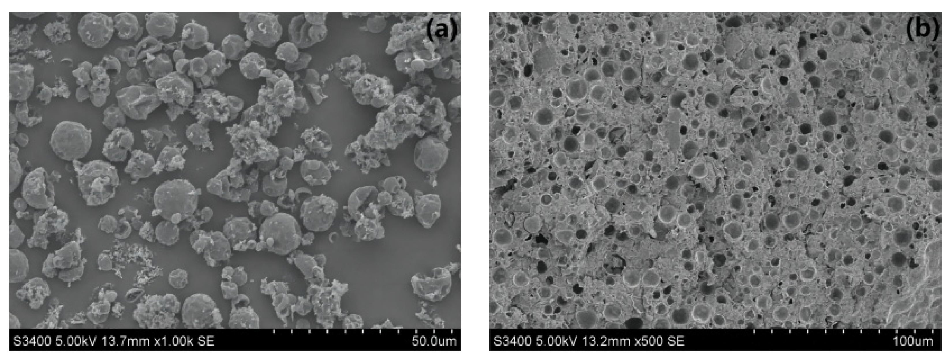
3.2.1. SEM Analysis

SEM was used to analyze the morphology and microstructure of PCMS and PCMS-PUR. First, Figure 3a shows the surface morphology of PCMS. It can be seen that the surface of the microcapsules presents microspheres with uniform size and regular shape. This feature is attributed to the stable oil-in-water emulsion formed at the preparation stage, where pure C14 is completely encapsulated in the shell material after 6 h of reaction and releases the latent heat of phase transition when the phase transition temperature is reached. Secondly, in Figure 3b, we show the attachment of PCMS to the polyurethane surface, where fine pores appear on the coating surface. This surface porous structure helps to improve the stability of the microcapsules and better protects the interior of the encapsulated material, thus extending its lifetime. In addition, the attachment of microcapsules improved the thermal storage properties of the polyurethane. Finally, the results of scanning electron microscopy tests confirmed that the prepared PCMS had a distinct core–shell structure, consistent with the typical structure of microcapsules.

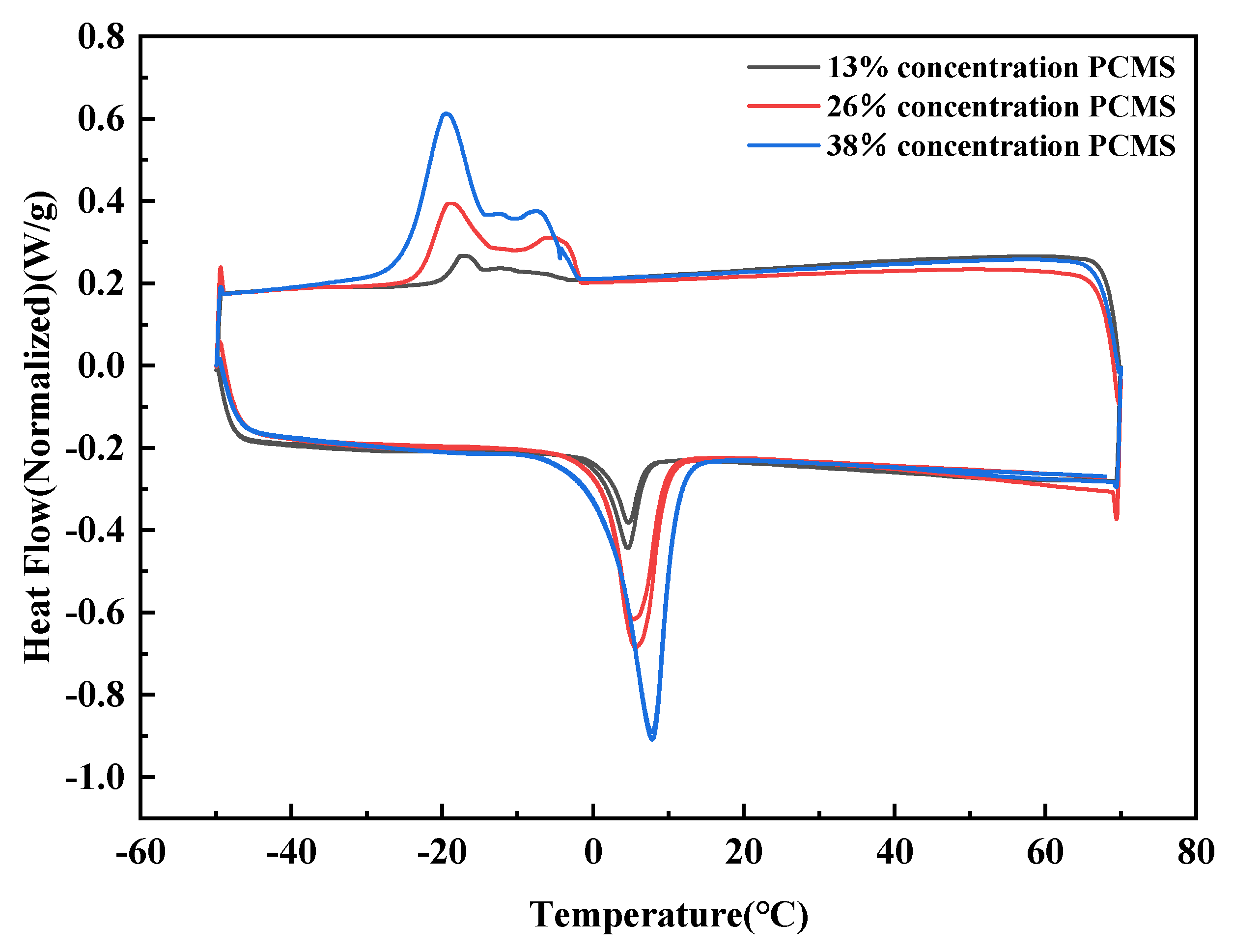
3.2.2. DSC Testing and Calculation of Encapsulation Efficiency and Energy Storage Efficiency

Since encapsulation efficiency and energy storage efficiency are crucial factors and prerequisites for evaluating phase change microcapsule materials, we conducted differential scanning calorimetry (DSC) testing on the prepared PCMS and evaluated their phase change performance.
We investigated the thermal storage characteristics of PCMS at different concentrations to determine the optimal concentration. Firstly, PCMS with concentrations of 13%, 26%, and 38% were selected, mixed with PUR, and subjected to DSC testing, as shown in Figure 4. The following results were obtained:
-
The melting enthalpy (ΔHm) of PCMS at 13% concentration was 3.7 J/g, and the crystallization enthalpy (ΔHc) was 3.3 J/g.
-
The melting enthalpy (ΔHm) of PCMS at 26% concentration was 14.7 J/g, and the crystallization enthalpy (ΔHc) was 14.0 J/g.
-
The melting enthalpy (ΔHm) of PCMS at 38% concentration was 24.9 J/g, and the crystallization enthalpy (ΔHc) was 27.0 J/g.
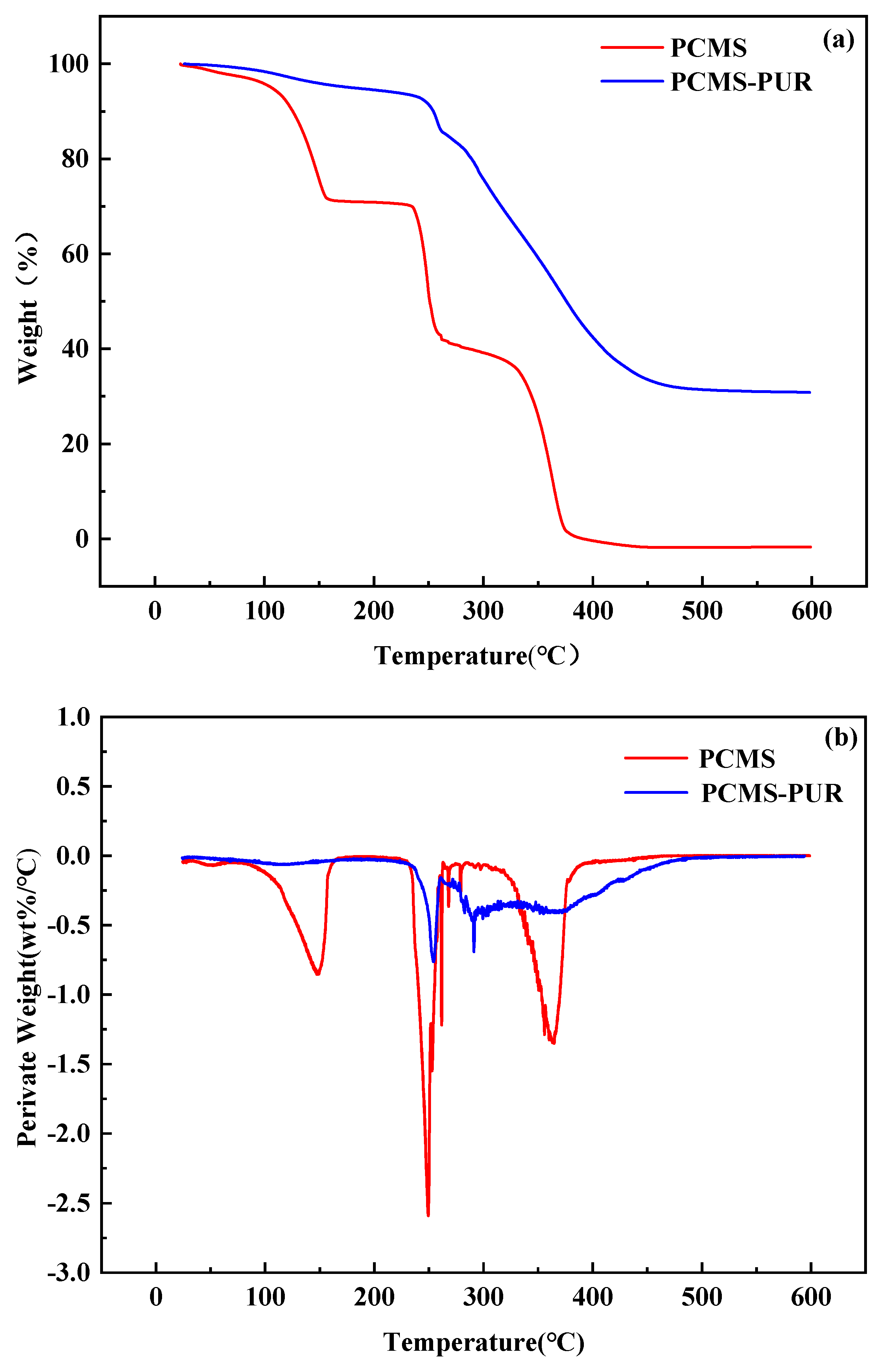
The phase change data are summarized in Table 1. From the results, it can be observed that the higher the concentration of PCMS, the greater the values of melting enthalpy and crystallization enthalpy. This indicates stronger interactions between molecules or ions, resulting in the need for more energy or the release of more energy during the transition between the solid and liquid states or between the solution and solid states. Therefore, the higher the concentration of PCMS, the more energy will be released when water droplets impact the surface.
In summary, we have selected PCMS with a concentration of 38% for further experiments. Next, we will conduct DSC testing and further analysis on C14, PCMS, and PCMS-PUR with a concentration of 38%.
Pure C14 exhibits dual-peak exothermic behavior during the cooling process and quasi-single-peak endothermic behavior during the melting process. Its melting point (Tm) is 7.1 °C, with a melting enthalpy of 172.9 J/g and a crystallization enthalpy of 182.2 J/g.
The PCMS have a Tm of 7.4 °C, a melting enthalpy of 90.8 J/g, and a crystallization enthalpy of 96.3 J/g. The higher crystallization enthalpy compared to the melting enthalpy indicates that more heat is released during the transition from the liquid to the solid state. The PCMS possess high melting and crystallization enthalpies, indicating their significant thermal storage capacity. Moreover, they exhibit sustained heat release within the range of −30 °C to 5 °C, allowing them to function over a wider temperature range and providing thermal storage and release capabilities.
As for the PCMS-PUR, its Tm is 7.8 °C, with a crystallization enthalpy of 24.9 J/g during the exothermic process and a TC of −19.5 °C. This indicates that the coating has a lower phase change temperature and a certain crystallization enthalpy, suggesting its thermal storage capacity. The negative TC value indicates the coating’s good stability and its ability to function at lower temperatures.
According to the following formula, the encapsulation efficiency K of the PCMS can be calculated from the melting enthalpy obtained from DSC:
K = Δ H m , m i c r o P C M Δ H m , P C M × 100 %
where ΔHm,micro-PCM and ΔHm,PCM represent the melting enthalpies of the PCMS and C14, respectively.
Based on the enthalpy of phase change, the energy storage efficiency (E) is typically used as an indicator of the storage and release of latent heat by microcapsules. It can be obtained using the following formula for the energy storage efficiency E of PCM materials:
E = Δ H m , m i c r o P C M + Δ H c , m i c r o P C M Δ H m , P C M + Δ H c , P C M × 100 %
where ΔHc,micro-PCM and ΔHc,PCM represent the crystallization enthalpies of the PCMS and C14, respectively. In comparison to C14, the phase change behavior and thermal storage performance of PCMS were studied. The DSC curve can be seen in Figure 5, and the phase change data are shown in Table 2.
Through calculations, we determined that the PCMS have an encapsulation efficiency and energy storage efficiency of 53%. This indicates excellent latent heat storage capacity during phase change, meeting its application requirements in energy storage.

3.2.3. TGA Testing

To assess the thermal stability of the synthesized PCMS, we conducted TGA testing on the samples, mainly characterizing the temperature of mass loss and the percentage of mass loss. The test conditions were conducted under a nitrogen atmosphere, with a heating rate of 10 °C/min in the temperature range of 30~600 °C.
The TGA curves and the derivative thermogravimetric (DTG) curves of PCMS and PCMS-PUR are shown in Figure 6 after data processing. From the graph, three distinct mass loss processes were observed within the temperature range of 30~600 °C. The first stage of mass loss occurred between 150~200 °C, mainly due to the evaporation of moisture adsorbed on the sample surface during heating. This process of mass loss did not affect the results of the TGA test. The second stage of mass loss occurred in the temperature range of 200~250 °C, during which the PCMS began to release the core material C14, leading to a sharp decrease in mass, and the overall structure may also be disrupted, resulting in mass loss. The third stage of mass loss occurred in the temperature range of 300~350 °C, mainly due to the decomposition of the shell material. As for the PCMS-PUR, it exhibited two mass loss processes, both within the temperature range of 250~300 °C, and the mass loss temperature range was higher than that of the PCMS. After 400 °C, the mass loss tended to stabilize.
These results indicate that the PCMS-PUR has good thermal stability in the temperature range of 30~250 °C, which means it can maintain stability over a wide temperature range, suitable for use on wind turbine blades to delay icing. In summary, the coating has potential applications and can be used to improve the anti-icing performance of wind turbine blades.

4. Ice Protection Testing

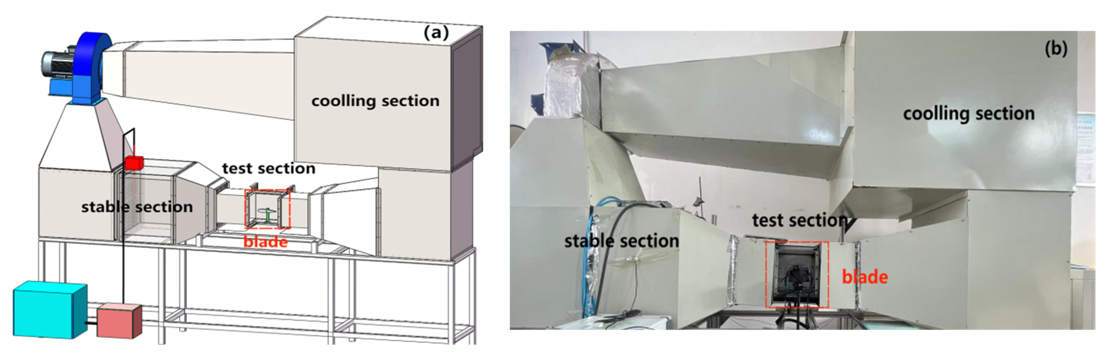
4.1. Icing Wind Tunnel System

The icing wind tunnel test is the most basic research means to carry out wind turbine anti-/de-icing technology. According to the type of wind tunnel, icing wind tunnels can be divided into open-circuit icing wind tunnels and return-flow icing wind tunnels. The open-circuit icing wind tunnel has a simple structure and utilizes the natural low-temperature environment for refrigeration, but due to the influence of the external environment, it is difficult to regulate the temperature of the test environment, which affects the test. The return-type icing wind tunnel, through the refrigeration system, adjusts the temperature of the test environment and the airflow after the test section through the pipeline back to re-use, so as to improve the efficiency of the refrigeration system and improve the quality of the flow field. At the present stage, most of the mainstream icing wind tunnels use reflow icing wind tunnels.
To verify the performance of the anti-icing coating, dynamic icing experiments were conducted using an icing wind tunnel system. Figure 7a shows a schematic diagram of the icing wind tunnel test system, while Figure 7b presents a photograph of the icing wind tunnel test site. In this system, supercooled air and supercooled water mist are uniformly mixed in the mixing section of the wind tunnel. They enter the test section to form a supercooled cloud mist flow. The blade model is mounted on a support in the test section, positioned at the center of the oncoming flow. When the oncoming flow with different temperatures and cloud mist parameters impacts the leading edge of the blade, icing phenomena can occur. The cross-section of the wind tunnel test section is sized at 250 mm × 250 mm, with a controllable temperature range of 0 °C to −20 °C and a wind speed range of 1 m/s to 20 m/s [30].

4.2. Dynamic Icing Test Scheme in the Wind Tunnel

To investigate the ice distribution on the surfaces of uncoated blades, blades coated with PUR coating, and blades coated with PCMS-PUR coating, the blades were horizontally fixed in the wind tunnel system. Flow rates of 40 mL/min and pressures of 0.3 MPa were selected, with temperatures set at −5, −10, and −15 °C under three different temperature conditions, and wind speeds of 3, 6, and 9 m/s were chosen under each temperature condition. The experiment scheme is outlined in Table 3.

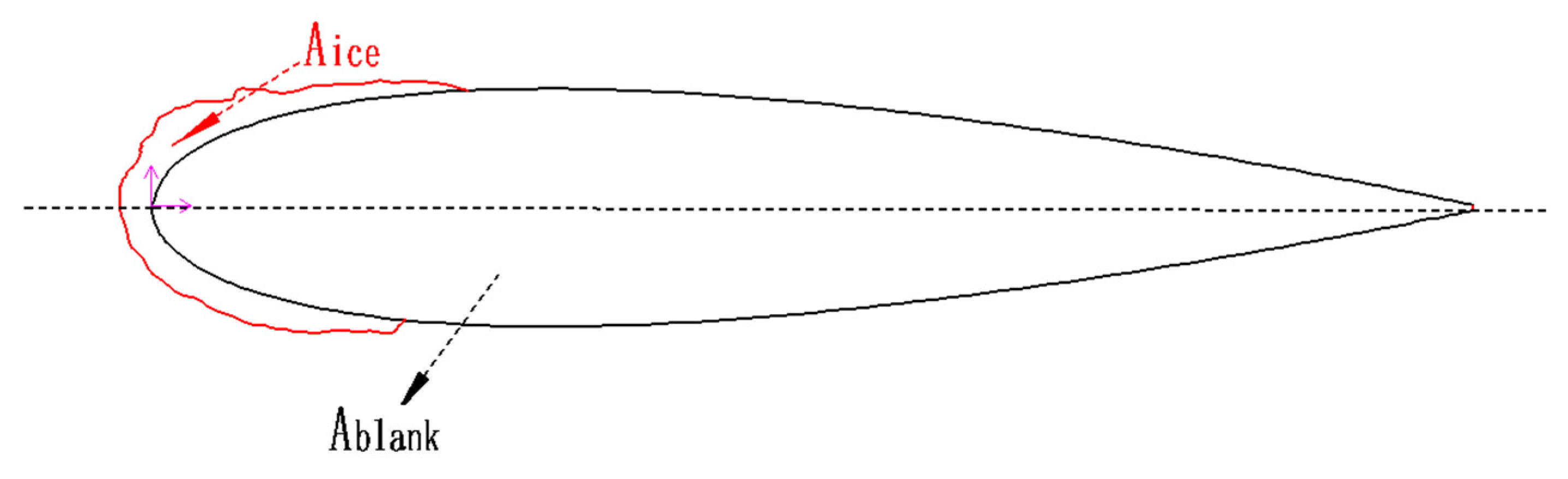
4.3. Evaluation Parameters

After the 5 min icing wind tunnel test was completed, photos of the icing on the three types of materials were captured using a high-speed camera (model 107 Phantom v5.1, boasting a resolution of 1024 × 1024 pixels). These photos were then processed using drawing software to depict the icing contours after 5 min.
To compare the anti-icing effectiveness of the uncoated, PUR coating, and PCMS-PUR coating, the following parameters were used as evaluation indicators:
  • Aice;
  • F;
F = Aice Ablank × 100 %
where F represents the ice coverage area ratio, Aice stands for the ice-covered area, and Ablank indicates the area of the blade contour. In Equation (3), as Aice decreases, F also decreases, indicating a better anti-icing effect of the coating. The schematic diagram of the blade ice coverage area ratio is shown in Figure 8.
3.
R.
The anti-icing rate of the PUR coating:
R 1 = A ice - ( Uncoated ) A ice - ( PUR ) A ice - ( Uncoated ) × 100 %
The anti-icing rate of the PCMS-PUR coating:
R 2 = A ice - ( Uncoated ) A ice - ( PCMS - PUR ) A ice - ( Uncoated ) × 100 %
where R represents the anti-icing rate. Aice-(Uncoated) is the icing area of the uncoated blade, Aice-(PUR) is the icing area of the PUR-coated blade, and Aice-(PCMS-PUR) is the icing area of the PCMS-PUR-coated blade. R1 is the anti-icing rate of the PUR coating, and R2 is the anti-icing rate of the PCMS-PUR coating. When the icing area on the surface of the coating decreases, the anti-icing effect is better, which means the coating can reduce ice formation. Therefore, when the value of R2 is lower, it indicates that the PCMS-PUR coating can reduce icing on the blade surface more effectively, demonstrating better anti-icing performance.

4.4. Results and Discussion

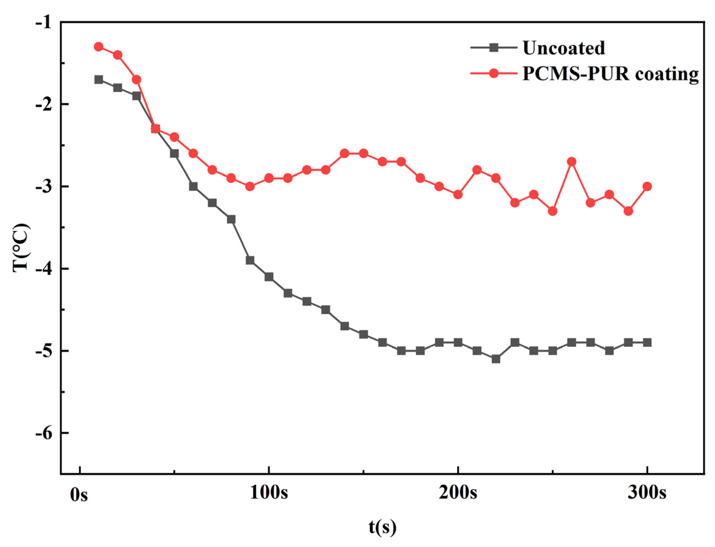
4.4.1. Surface Temperature

To explore the solidification heat release capability of the PCMS-PUR coating, a thermal imager was used to record the temperature variation at the leading edge of the blades during the icing wind tunnel test, as shown in Figure 9. Under the experimental conditions of −5 °C temperatures and 3 m/s wind speeds, the surface temperature changes of the blades with and without the coating were compared over 5 min. The results showed that at the beginning of the experiment, the surface temperature of the uncoated blade was −1.7 °C. Over time, the temperature gradually decreased, eventually reaching −5.9 °C. This indicates that the uncoated blade experienced significant cooling under icing conditions, with the surface temperature dropping rapidly. In contrast, the surface temperature of the blade coated with the PCMS-PUR coating started at −1.3 °C. Compared to the uncoated blade, the temperature decrease was smaller over the same period, stabilizing at around −3 °C in the end. This demonstrates the solidification heat release capability of the coating. The PCMS-PUR coating releases heat when encountering low temperatures, resulting in relatively stable surface temperatures of the coating.
Therefore, blades coated with PCMS-PUR can effectively slow down the rate of surface temperature decrease in low-temperature environments, significantly reducing the likelihood of icing. This provides strong support for improving wind turbine performance and reliability under adverse weather conditions.

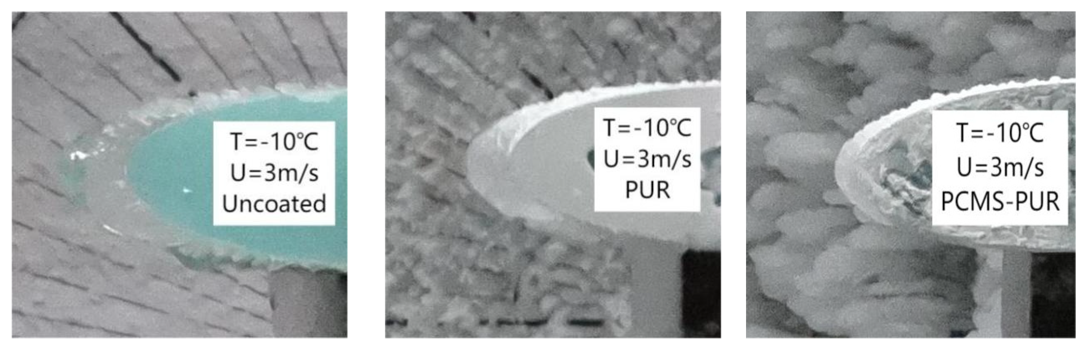
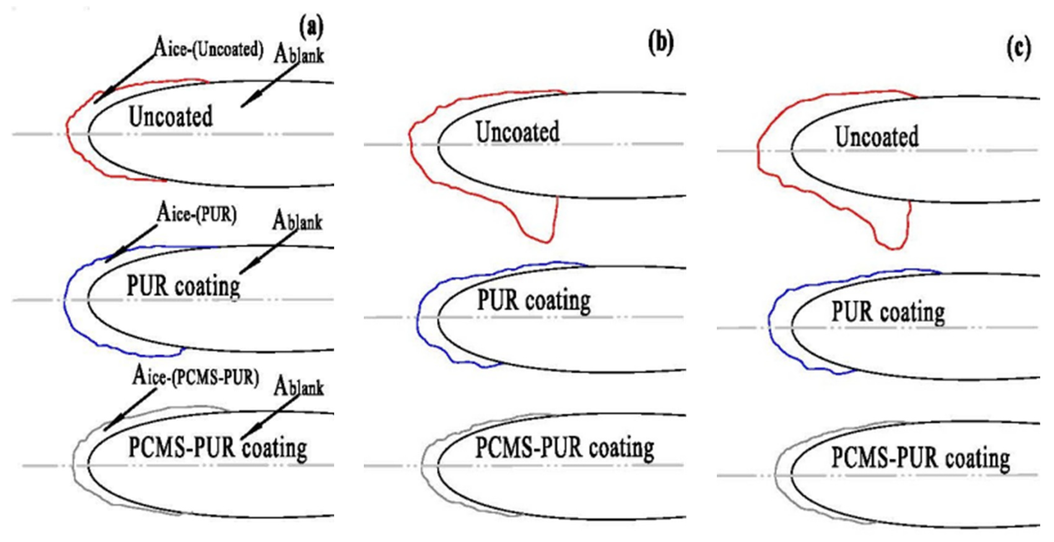
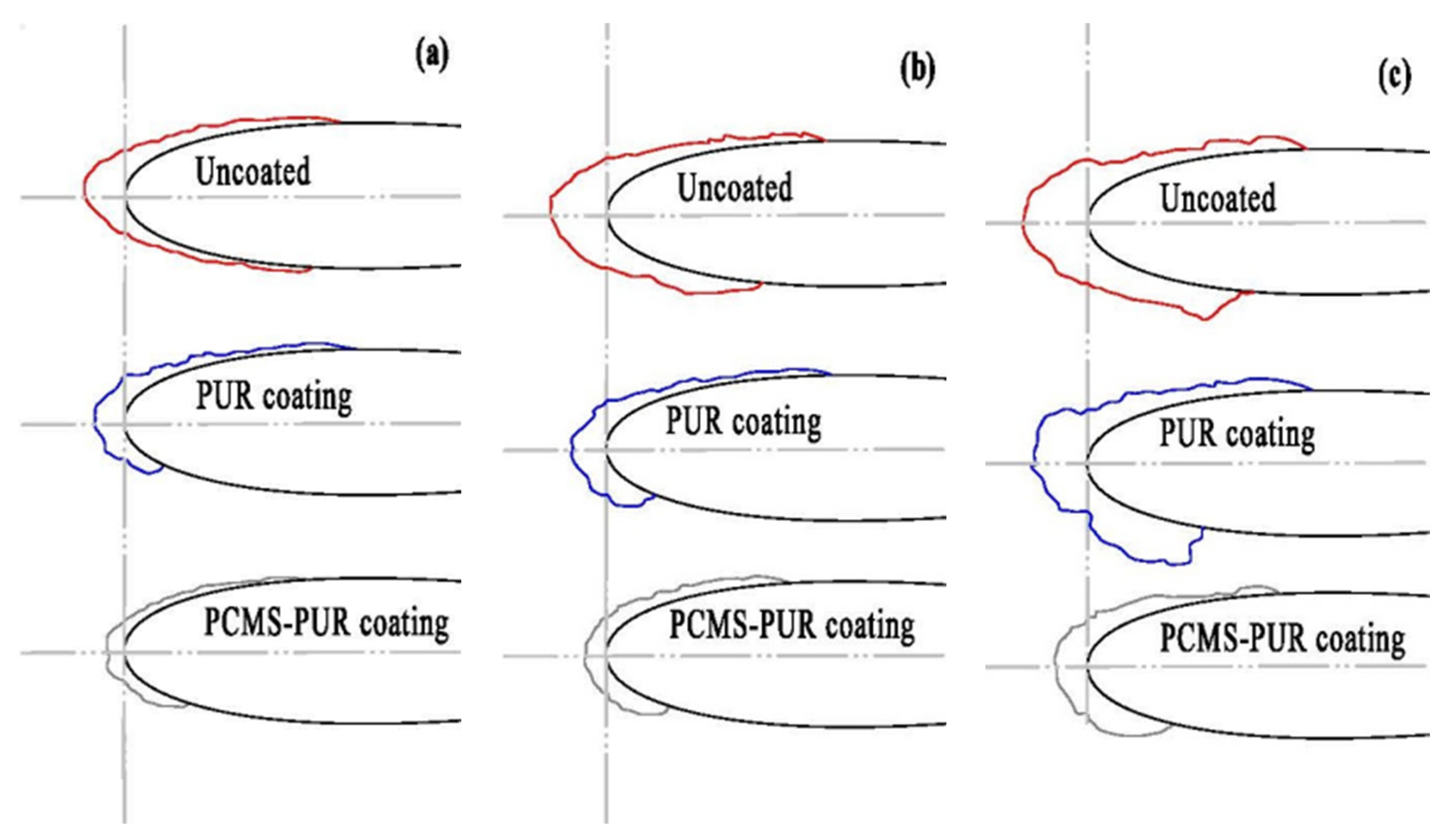
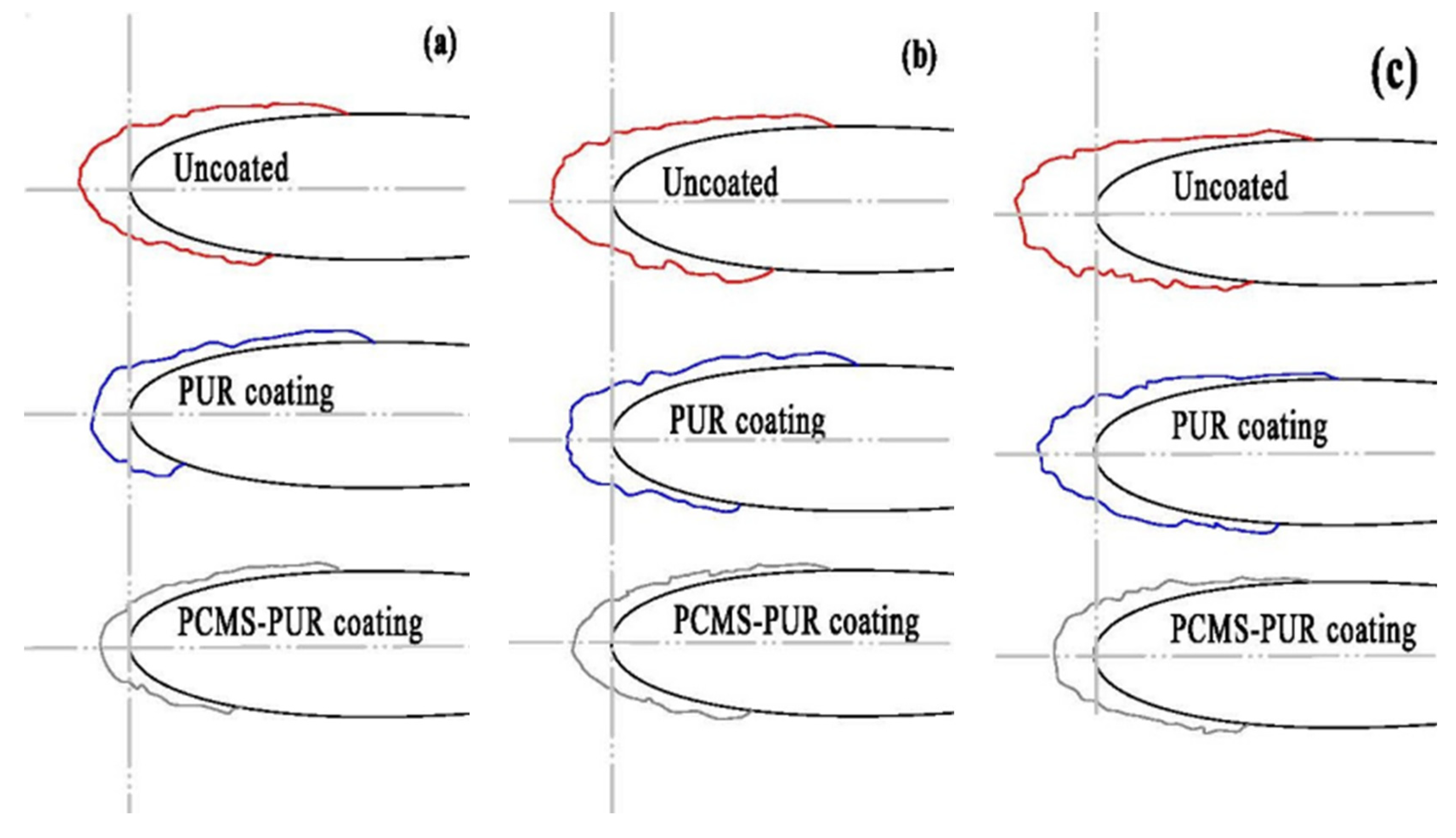
4.4.2. Icing Distribution

The test results for icing after 5 min at −10 °C and 3 m/s for untreated blades, PUR-coated blades, and blades coated with PCMS-PUR are shown in Figure 10.
The icing shapes on the surface of uncoated, PUR-coated, and PCMS-PUR-coated blades were processed using plotting software. Figure 11, Figure 12, and Figure 13 illustrate the icing patterns of the three coatings at wind speeds of 3 m/s, 6 m/s, and 9 m/s and temperatures of −5 °C, −10 °C, and −15 °C, respectively. Blade icing occurred mainly at the leading edge.
When the temperature is constant, the icing tends to increase with the gradual increase in wind speed for all three coatings. This is attributed to the increase in wind speed, the number of impacts of supercooled water droplets on the blade surface per unit of time increases, leading to an increase in the liquid water content, which in turn leads to an increase in the amount of icing on the blade surface. At −5 °C, the amount of ice formation significantly increases on the uncoated leading edge of the blades. This is because the uncoated blades are directly exposed to the environment without any protective layer, making them more susceptible to the influence of supercooled water droplets, resulting in increased ice formation. The increase in icing at the leading edge of the PCMS-PUR-coated blade is smaller because the PCMS-PUR-coated blade is capable of releasing heat at low temperatures, which slows down the sharp decrease in the blade surface temperature and reduces the speed of the freezing of supercooled water droplets. Thus, the increase in the amount of icing is slower.
When the wind speed is certain, with the gradual decrease in temperature, the icing volume of all three coatings will increase. This is because at lower temperatures, water vapor in the air is more likely to condense into the form of supercooled water droplets. Subcooled water droplets are water droplets in the air that are below freezing temperature but still in the liquid state. When these supercooled, water droplets come into contact with the blade surface and they will quickly freeze into ice, increasing the amount of icing on the blade surface. In the case of a wind speed of 6 m/s and a temperature of −5 °C, for example, icicles appeared on the uncoated blade. This phenomenon may be due to the difference in thermal conductivity between the FRP blade and the ice layer. The relatively high thermal conductivity of the ice layer results in faster heat transfer from the blade surface to the ice layer, causing the supercooled water droplets to freeze quickly. However, the lower thermal conductivity of the FRP blades results in a slower rate of heat conduction, so the time required to reach thermal equilibrium between the supercooled water droplets and the blade surface increases, prolonging the freezing time of the supercooled water droplets. During this time, due to the combined effect of airflow and gravity, the unfrozen water droplets begin to flow downward and gradually converge to form icicles. At lower temperatures, such as −10 °C and −15 °C, the freezing speed of the supercooled water droplets is faster due to the lower ambient temperature, making the unfrozen water droplets unable to flow and quickly freeze on the surface of the blades, which reduces the generation of ice columns.
At the same temperature and wind speed, the blank blade has the largest icing area, while the icing area of the PCMS-PUR-coated blade is significantly smaller than that of the PUR-coated blade only. This is because when PCMS-PUR comes into contact with supercooled water, its temperature drops to the freezing point, causing the internal phase change material to solidify, converting the chemical energy into heat, which is then released. This heat transfers to the blade and the water impedes the process of water vapor condensing into ice on the PCMS surface. This phenomenon can be attributed to the properties of the PCMS, such as its solidification temperature and heat release capacity, as well as the structure and properties of the microcapsule surface, which are very effective in preventing ice formation or slowing down ice growth. Liquid phase change microcapsules solidify on contact with surface water droplets and release heat, thus preventing water vapor from condensing on the surface.

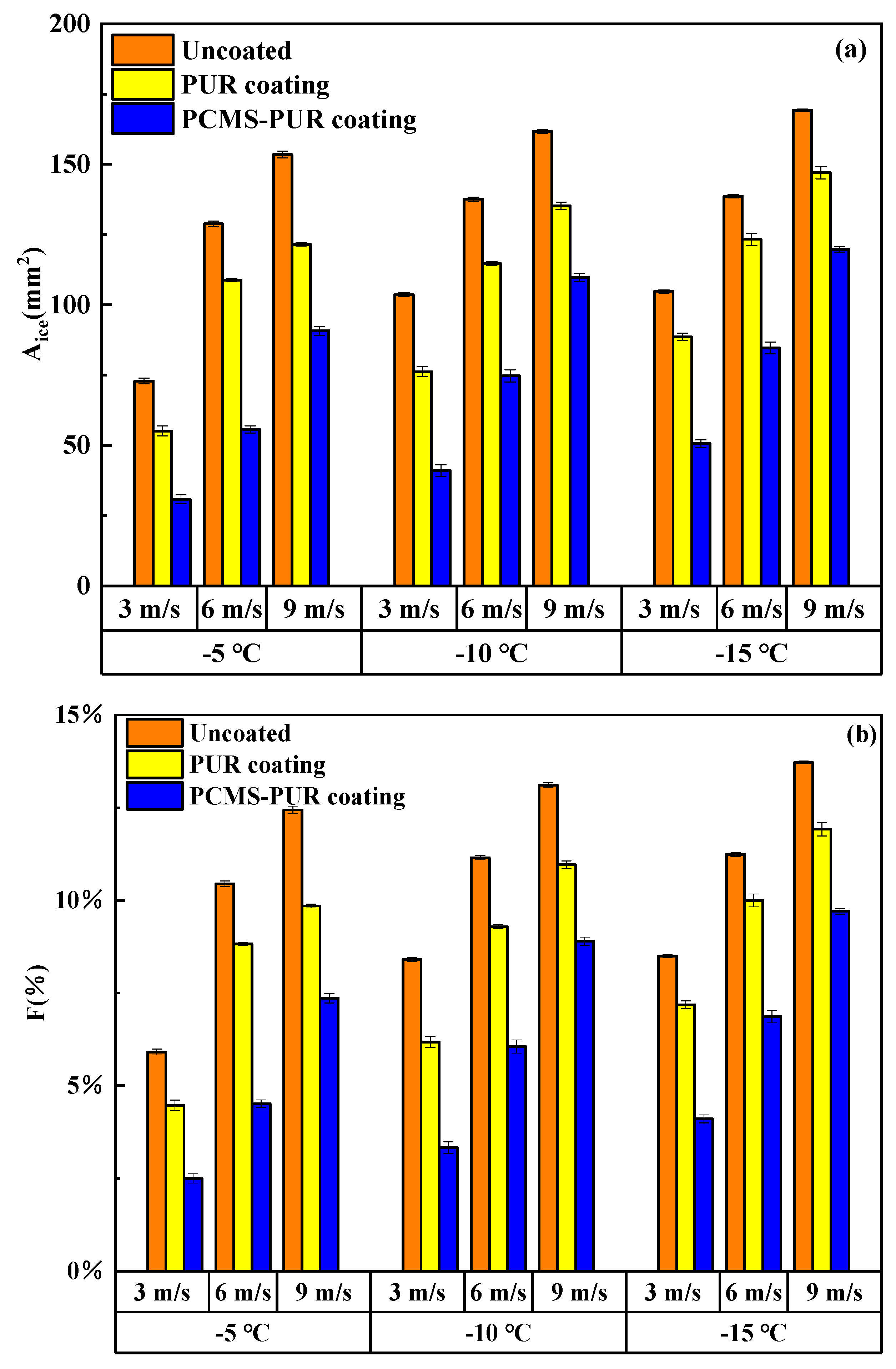
4.4.3. Ice Area Ratio

The bar graph in Figure 14 clearly illustrates the changes in the ice area and ice area ratio on the surfaces of different coated and uncoated blades. When the wind speed is 3 m/s and the temperature is −5 °C, the ice area ratio of the uncoated blade is 5.9%, while that of the blade with PCMS-PUR is 2.5%. When the wind speed is 3 m/s and the temperature is −10 °C, the ice area ratio of the uncoated blade is 8.4%, while that of the blade with PCMS-PUR is 3.3%. When the wind speed is 3 m/s and the temperature is −15 °C, the ice area ratio of the uncoated blade is 8.5%, while that of the blade with PCMS-PUR is 4.1%. With the decrease in ambient temperature, the ice area at the leading edge of all blades tends to increase. This is because at lower temperatures, water is more likely to condense into ice at the leading edge of the blade, leading to an increase in the ice area. The PCMS-PUR exhibits good performance in reducing ice formation on the blade, especially at lower temperatures and wind speeds, demonstrating significant anti-icing effects.
When the temperature is −15 °C and the wind speed is 3 m/s, the ice area ratio of the uncoated blade is 12.4%, while that of the blade with PCMS-PUR is 7.4%. When the temperature is −15 °C and the wind speed is 6 m/s, the ice area ratio of the uncoated blade is 11.2%, while that of the blade with PCMS-PUR is 6.9%. When the temperature is −15 °C and the wind speed is 9 m/s, the ice area ratio of the uncoated blade is 13.7%, while that of the blade with PCMS-PUR is 9.7%. At the same wind speed, with the decrease in temperature, the ice area ratio of both the uncoated blade and the blade with PCMS-PUR tends to increase. This indicates that icing becomes more severe at lower temperatures. In contrast, the blade with PCMS-PUR exhibits a lower ice area ratio. This demonstrates that the coating has good anti-icing effects under different conditions and can effectively reduce blade icing, thereby improving the performance and reliability of wind turbines.
In summary, these data help evaluate the anti-icing performance of the PCMS-PUR under different environmental conditions, providing important references for wind turbine operation.
A comparison was made with the results of previous studies, as shown in Figure 15. In this study, the icing area was 55.7 mm2, 74.7 mm2, and 84.7 mm2 for a wind speed of 6 m/s and ambient temperatures of −5 °C, −10 °C, and −15 °C, respectively, whereas in the study by Liu et al. [13], the icing areas were 88.3 mm2 and 109.3 mm2. A comparison shows that the results of this paper have minor differences from previous studies. These differences mainly stem from the differences in experimental conditions and coatings. However, the n-tetradecane phase change microencapsulated polyurethane coating used in this study showed better anti-icing results.

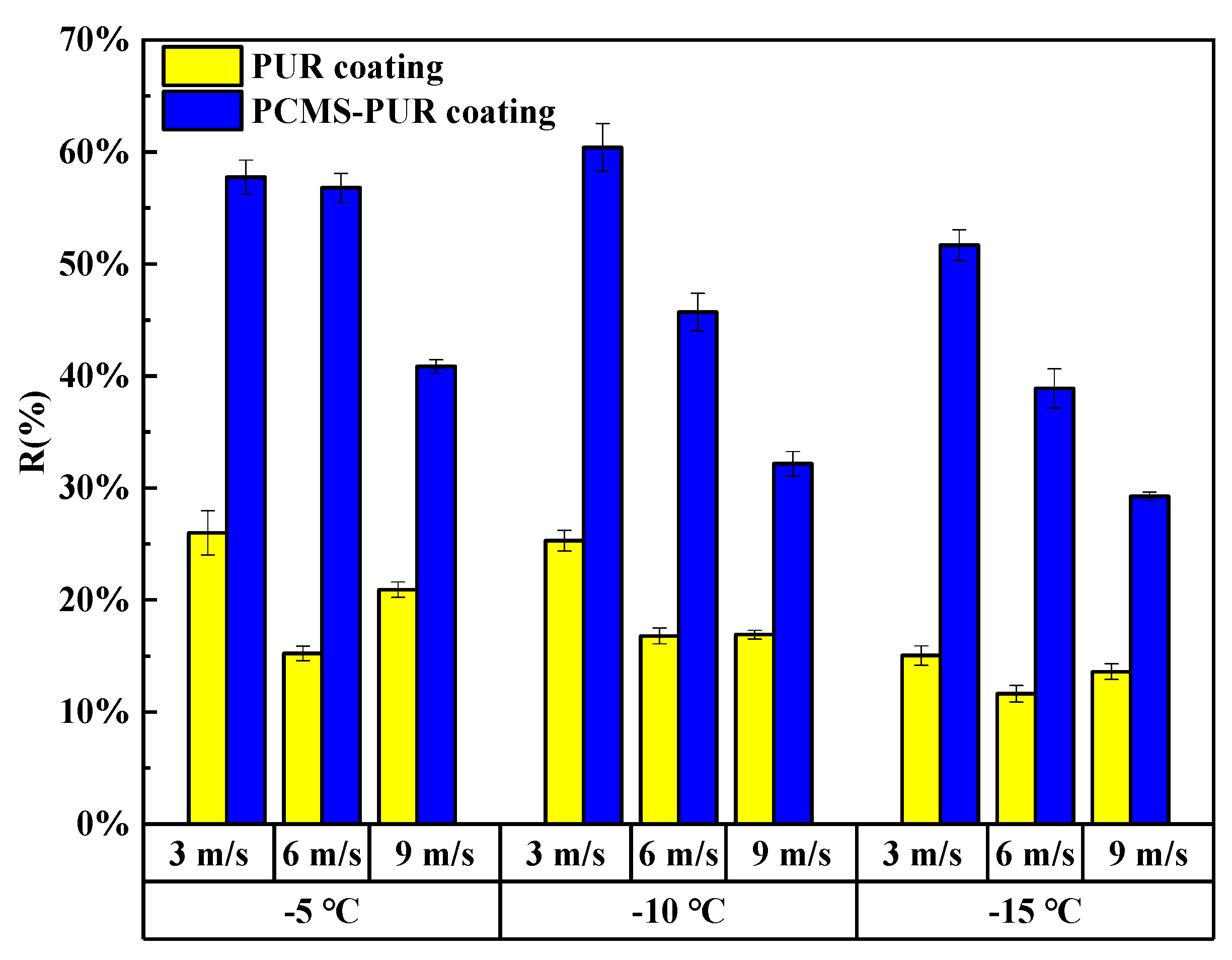
4.4.4. Anti-Icing Rate Analysis

Figure 16 depicts the variations in the anti-icing rates of the two coatings. At an ambient temperature of −15 °C and a wind speed of 3 m/s, the ice protection rate was 51.7%; at an ambient temperature of −5 °C and a wind speed of 3 m/s, the ice protection rate was 57.7%; and at an ambient temperature of −10 °C and a wind speed of 3 m/s, the ice protection rate was 60.4%. Under the same wind speed condition, the highest anti-icing rate was found at a temperature of −10 °C. This phenomenon may be related to the properties of the PCMS-PUR coating since the phase transition temperature of C14 is usually around −10 °C. In this temperature range, the anti-icing coating may release more heat. This heat release helps prevent supercooled water droplets from freezing on the blade surface and reduces leading-edge icing, which improves the efficiency of the anti-icing coating and enhances operational stability and durability in adverse weather conditions. The anti-icing rate is 40.9% when the ambient temperature is −5 °C and the wind speed is 9 m/s; 56.8% when the ambient temperature is −5 °C and the wind speed is 6 m/s; and 57.7% when the ambient temperature is −5 °C and the wind speed is 3 m/s. Under the same temperature conditions, the highest anti-icing rate was found when the wind speed was 3 m/s. With the increase in wind speed, the anti-icing rate gradually decreased. These data further validate the effectiveness of PCMS-PUR coating in reducing icing on the leading edge of the blade.
Coating wind turbine blades with PCMS-PUR significantly improves their anti-icing performance, further validating the potential of this coating in mitigating icing problems.

5. Conclusions and Discussion

  • In this study, PCMS were prepared via interfacial polymerization and added into PUR coating to form PCMS-PUR coating, which was applied to wind turbine blades. The enthalpy of melting of the microcapsules was 90.8 J/g, and the enthalpy of crystallization was 96.3 J/g, indicating that they have excellent thermal energy storage capacity.
  • Through the icing wind tunnel experiment, it is found that at a certain temperature and a certain wind speed, the leading edge of the uncoated blade is more likely to be affected by the supercooled water droplets, leading to an increase in the icing amount. The PCMS-PUR coating can release heat at low temperatures, slowing down the sharp decrease in the surface temperature of the blade, which makes the supercooled droplets slow down the speed of icing. Therefore, the increase in icing is slow.
  • When the wind speed is certain, the icing area ratio gradually increases as the temperature decreases. When the wind speed is 3 m/s and the temperature is −15 °C, the icing area ratio of the uncoated blade is 8.5%, while the icing area ratio of the PCMS-PUR coating blade is 4.1%. When the temperature is certain, the icing area ratio increases gradually with the increase in wind speed. When the temperature is −15 °C and the wind speed is 6 m/s, the icing area ratio of the uncoated blade is 11.2%, while the icing area ratio of the PCMS-PUR coating blade is 6.9%. In comparison, the icing area ratio of the uncoated blade is higher. This indicates that PCMS-PUR coating is more effective in delaying icing and helps to reduce the degree of blade icing.
  • At different wind speeds and the same temperatures, compared with the uncoated blade, the icing area of the blade coated with PCMS-PUR coating is significantly reduced, and the anti-icing rate is as high as 60.41%. At different temperatures and the same wind speed, the anti-icing rate is as high as 57.7%, which indicates that PCMS-PUR coating shows good anti-icing performance at different wind speeds and temperatures, which can effectively reduce the icing on the leading edge of the blade and improve the performance and reliability of the wind turbine.
  • PCMS is able to absorb and release a large amount of heat during the phase change process and has good heat storage and release ability, which is suitable for regulating and stabilizing the surface temperature of the blades, thus delaying the icing. This study provides basic research data for exploring new anti-icing methods and reveals the great potential of PCMS in delaying the icing of wind turbine blades.
Discussion: Through this experimental study, it was found that phase change microcapsules can effectively maintain the blade surface temperature in a high range and avoid its excessive reduction to the ambient temperature level. By adjusting the concentration and content of phase change microcapsules, different degrees of anti-icing effects on wind turbine blades can be realized. Future research will continue to explore more optimized phase change microcapsule concentrations to further improve coating performance and increase wind turbine blade surface temperatures.

Author Contributions

Conceptualization, Y.W., Y.L. and F.F.; Formal Analysis Y.W., Y.L. and F.F.; Funding Acquisition, F.F.; Investigation, Y.W. and H.S.; Methodology, Y.W. and Z.S.; Supervision, Y.L. and F.F.; Validation, Y.W. and H.S.; Writing—Original Draft, Y.W.; Writing—Review and Editing, Y.L. and F.F. All authors have read and agreed to the published version of the manuscript.

Funding

This work was supported by Project grant NO.52076035 supported by the National Natural Science Foundation of China (NSFC).

Institutional Review Board Statement

Not applicable.

Informed Consent Statement

Not applicable.

Data Availability Statement

Data are contained within the article.

Conflicts of Interest

The authors declare no conflict of interest.

References

  1. Balakrishnan, P.; Shabbir, M.S.; Siddiqi, A.F.; Wang, X. Current status and future prospects of renewable energy: A case study. Energy Sources Part A Recovery Util. Environ. Eff. 2020, 42, 2698–2703. [Google Scholar] [CrossRef]
  2. Tong, G.; Li, Y.; Tagawa, K.; Feng, F. Effects of blade airfoil chord length and rotor diameter on aerodynamic performance of straight-bladed vertical axis wind turbines by numerical simulation. Energy 2023, 265, 126325. [Google Scholar] [CrossRef]
  3. Zheng, C.W.; Li, C.Y.; Pan, J.; Liu, M.Y.; Xia, L.L.J.R.; Reviews, S.E. An overview of global ocean wind energy resource evaluations. Energy Rev. 2016, 53, 1240–1251. [Google Scholar] [CrossRef]
  4. Deshmukh, M.K.G.; Sameeroddin, M.; Abdul, D.; Abdul Sattar, M. Renewable energy in the 21st century: A review. Mater. Today Proc. 2023, 80, 1756–1759. [Google Scholar] [CrossRef]
  5. Li, Y.; Yang, S.; Feng, F.; Tagawa, K. A review on numerical simulation based on CFD technology of aerodynamic characteristics of straight-bladed vertical axis wind turbines. Energy Rep. 2023, 9, 4360–4379. [Google Scholar] [CrossRef]
  6. Rastayesh, S.; Long, L.; Dalsgaard Sørensen, J.; Thöns, S. Risk Assessment and Value of Action Analysis for Icing Conditions of Wind Turbines Close to Highways. Energies 2019, 12, 2653. [Google Scholar] [CrossRef]
  7. Katsaprakakis, D.A.; Papadakis, N.; Ntintakis, I. A Comprehensive Analysis of Wind Turbine Blade Damage. Energies 2021, 14, 5974. [Google Scholar] [CrossRef]
  8. Kreutz, M.; Ait-Alla, A.; Varasteh, K.; Oelker, S.; Greulich, A.; Freitag, M.; Thoben, K.-D. Machine learning-based icing prediction on wind turbines. Procedia CIRP 2019, 81, 423–428. [Google Scholar] [CrossRef]
  9. Gao, L.; Hu, H. Wind turbine icing characteristics and icing-induced power losses to utility-scale wind turbines. Proc. Natl. Acad. Sci. USA 2021, 118, e2111461118. [Google Scholar] [CrossRef]
  10. Swenson, L.; Gao, L.; Hong, J.; Shen, L. An efficacious model for predicting icing-induced energy loss for wind turbines. Appl. Energy 2022, 305, 117809. [Google Scholar] [CrossRef]
  11. Lopera-Valle, A.; McDonald, A. Flame-sprayed coatings as de-icing elements for fiber-reinforced polymer composite structures: Modeling and experimentation. Int. J. Heat Mass Transf. 2016, 97, 56–65. [Google Scholar] [CrossRef]
  12. Golewski, P.; Budka, M. The Influence of Flame Exposure and Solid Particle Erosion on Tensile Strength of CFRP Substrate with Manufactured Protective Coating. Materials 2024, 17, 1203. [Google Scholar] [CrossRef] [PubMed]
  13. Liu, Z.; Li, Y.; He, Z. Ice-phobic properties of MoS2-loaded rice straw biogas residue biochar-based photothermal and anti-corrosion coating with low oxygen to carbon ratio. Biochar 2023, 5, 74. [Google Scholar] [CrossRef]
  14. Wei, X.; Cai, F.; Wang, J. Electrothermal/photothermal superhydrophobic coatings based on micro/nano graphite flakes for efficient anti-icing and de-icing. Prog. Org. Coat. 2023, 182, 107696. [Google Scholar] [CrossRef]
  15. Zhuang, A.; Li, C.; Yu, J.; Lu, Y. The Glaze Icing Performance of a Robust Superhydrophobic Film Composed of Epoxy Resin and Polydimethylsiloxane. Coatings 2023, 13, 1271. [Google Scholar] [CrossRef]
  16. Piscitelli, F.; Chiariello, A.; Dabkowski, D.; Corraro, G.; Marra, F.; Di Palma, L. Superhydrophobic Coatings as Anti-Icing Systems for Small Aircraft. Aerospace 2020, 7, 2. [Google Scholar] [CrossRef]
  17. Sullivan, A.; Duan, X.; Yang, J. Energy-efficient anti-icing performance of a hybrid superhydrophobic and electrothermal coating on metallic substrates. Mater. Chem. Phys. 2023, 301, 127700. [Google Scholar] [CrossRef]
  18. Tong, W.; Xiong, D.; Wang, N.; Wu, Z.; Zhou, H. Mechanically robust superhydrophobic coating for aeronautical composite against ice accretion and ice adhesion. Compos. Part B Eng. 2019, 176, 107267. [Google Scholar] [CrossRef]
  19. Qin, C.; Mulroney, A.T.; Gupta, M.C. Anti-icing epoxy resin surface modified by spray coating of PTFE Teflon particles for wind turbine blades. Mater. Today Commun. 2020, 22, 100770. [Google Scholar] [CrossRef]
  20. Peng, G.; Dou, G.; Hu, Y.; Sun, Y.; Chen, Z. Phase Change Material (PCM) Microcapsules for Thermal Energy Storage. Adv. Polym. Technol. 2020, 2020, 9490873. [Google Scholar] [CrossRef]
  21. Liu, H.; Wang, X.; Wu, D. Innovative design of microencapsulated phase change materials for thermal energy storage and versatile applications: A review. Sustain. Energy Fuels 2019, 3, 1091–1149. [Google Scholar]
  22. Sinaga, R.; Darkwa, J.; Omer, S.A.; Worall, M. The microencapsulation, thermal enhancement, and applications of medium and high-melting temperature phase change materials: A review. Int. J. Energy Res. 2022, 46, 10259–10300. [Google Scholar] [CrossRef]
  23. Mahadik, S.A.; Parale, V.; Vhatkara, R.S.; Mahadik, D.B.; Kavale, M.S.; Wagh, P.B.; Gupta, S.; Gurav, J. Superhydrophobic silica coating by dip coating method. Appl. Surf. Sci. 2013, 277, 67–72. [Google Scholar] [CrossRef]
  24. Chou, C.-S.; Chou, F.-C.; Kang, J.-Y. Preparation of ZnO-coated TiO2 electrodes using dip coating and their applications in dye-sensitized solar cells. Powder Technol. 2012, 215–216, 38–45. [Google Scholar] [CrossRef]
  25. Lu, S.; Shen, T.; Xing, J.; Song, Q.; Shao, J.; Zhang, J.; Xin, C. Preparation and characterization of cross-linked polyurethane shell microencapsulated phase change materials by interfacial polymerization. Mater. Lett. 2018, 211, 36–39. [Google Scholar] [CrossRef]
  26. Lu, S.; Wang, Q.; Zhou, H.; Shi, W.; Zhang, Y.; Huang, Y. Preparation of High Thermo-Stability and Compactness Microencapsulated Phase Change Materials with Polyurea/Polyurethane/Polyamine Three-Composition Shells through Interfacial Polymerization. Materials 2022, 15, 2479. [Google Scholar] [CrossRef]
  27. Zhang, F.; Fan, J.-B.; Wang, S. Interfacial Polymerization: From Chemistry to Functional Materials. Angew. Chem. Int. Ed. 2020, 59, 21840–21856. [Google Scholar] [CrossRef]
  28. Raaijmakers, M.J.T.; Benes, N.E. Current trends in interfacial polymerization chemistry. Prog. Polym. Sci. 2016, 63, 86–142. [Google Scholar] [CrossRef]
  29. Zhu, X.; Li, X.; Shen, J.; Wang, B.; Mao, Z.; Xu, H.; Feng, X.; Sui, X. Stable microencapsulated phase change materials with ultrahigh payload for efficient cooling of mobile electronic devices. Energy Convers. Manag. 2020, 223, 113478. [Google Scholar] [CrossRef]
  30. Liu, Z.; Feng, F.; Li, Y.; Sun, Y.; Tagawa, K. A corncob biochar-based superhydrophobic photothermal coating with micro-nano-porous rough-structure for ice-phobic properties. Surf. Coat. Technol. 2023, 457, 129299. [Google Scholar] [CrossRef]
Figure 1. Research Roadmap.
Coatings 14 00645 g001
Figure 2. (a) Blade Model; (b) Wind Turbine Blade with Coating.
Coatings 14 00645 g002
Figure 3. (a) SEM Image of PCMS at 1000× Magnification; (b) SEM Image of PCMS-PUR Coating at 500 × Magnification.
Coatings 14 00645 g003
Figure 4. DSC Curves of PCMS at Different Concentrations.
Coatings 14 00645 g004
Figure 5. DSC Curves of C14, PCMS, and PCMS-PUR.
Coatings 14 00645 g005
Figure 6. (a) TGA Curves of PCMS and PCMS-PUR; (b) DTG Curves of PCMS and PCMS-PUR.
Coatings 14 00645 g006
Figure 7. (a) Schematic diagram of the icing wind tunnel test system; (b) actual photo of the icing wind tunnel test system.
Coatings 14 00645 g007
Figure 8. Schematic Diagram of Ice Coverage Area Ratio.
Coatings 14 00645 g008
Figure 9. Surface Temperature Variation with and without coating.
Coatings 14 00645 g009
Figure 10. Temperatures of −10 °C and wind speeds of 3 m/s on an icing physical map.
Coatings 14 00645 g010
Figure 11. (a) T = −5 °C U = 3 m/s; (b) T = −5 °C U = 6 m/s; (c) T= −5 °C U = 9 m/s.
Coatings 14 00645 g011
Figure 12. (a) T = −10 °C U = 3 m/s; (b) T = −10 °C U = 6 m/s; (c) T = −10 °C U = 9 m/s.
Coatings 14 00645 g012
Figure 13. (a) T = −15 °C U = 3 m/s; (b) T = −15 °C U = 6 m/s; (c) T = −15 °C U = 9 m/s.
Coatings 14 00645 g013
Figure 14. (a) Icing area: Aice; (b) icing area ratio: F.
Coatings 14 00645 g014
Figure 15. Comparison of results.
Coatings 14 00645 g015
Figure 16. Anti-icing rate: R.
Coatings 14 00645 g016
Table 1. PCMS-PUR at Different Concentrations.
ConcentrationMelting ProcessCrystallization Process
Tm (°C)ΔHm (J/g)Tc (°C)ΔHc (J/g)
13%4.73.7−17.33.3
26%5.414.7−18.814.0
38%7.824.9−19.527.0
Tm: melting temperature; ΔHm: enthalpy of melting; Tc: crystallization temperature; ΔHc: enthalpy of crystallization.
Table 2. Phase Change Data.
SampleK
(%)
E
(%)
Melting ProcessCrystallization Process
Tm
(°C)
ΔHm
(J/g)
Tc
(°C)
Tr
(°C)
ΔHc
(J/g)
C14 7.1172.90.8 182.2
PCMS53537.490.8−16.9−1.796.3
PCMS-PUR 7.824.9−19.5 27.0
Tm: melting temperature; ΔHm: enthalpy of melting; Tc: crystallization temperature; ΔHc: enthalpy of crystallization; Tr: reference temperature.
Table 3. Experiment Scheme.
Working ConditionCoating TypeTemperature
(°C)
Wind Velocity
(m/s)
1Uncoated−5 °C/−10 °C/−15 °C3 m/s
2PUR coating3 m/s
3PCMS-PUR coating3 m/s
4Uncoated6 m/s
5PUR coating6 m/s
6PCMS-PUR coating6 m/s
7Uncoated9 m/s
8PUR coating9 m/s
9PCMS-PUR coating9 m/s
Disclaimer/Publisher’s Note: The statements, opinions and data contained in all publications are solely those of the individual author(s) and contributor(s) and not of MDPI and/or the editor(s). MDPI and/or the editor(s) disclaim responsibility for any injury to people or property resulting from any ideas, methods, instructions or products referred to in the content.

