Article

Structural Evolution and Fracture Mechanism of WC-Particle-Reinforced FeCoCrNiMn High-Entropy Alloy Coatings

1
School of Material Science and Engineering, Taiyuan University of Science and Technology, 66 Waliu Road, Taiyuan 030024, China
2
School of Mechanical Engineering and Automation, University of Science and Technology, Anshan 114051, China
*
Authors to whom correspondence should be addressed.
Coatings 2024, 14(4), 403; https://doi.org/10.3390/coatings14040403
Submission received: 20 February 2024 / Revised: 23 March 2024 / Accepted: 25 March 2024 / Published: 29 March 2024
(This article belongs to the Section Surface Characterization, Deposition and Modification)

Abstract

:
A hard-particle-reinforced high-entropy alloy (HEA) coating shows significant potential for tribological applications, but relatively little work on the fracture mechanism of the coating has been reported. In this work, the FeCoCrNiMn HEA coatings, doped with varying contents of WC, were fabricated using a plasma surfacing technique. The structure, mechanical properties, and fracture behaviors of these coatings were investigated through X-ray diffraction (XRD), scanning electron microscopy (SEM), and hardness and tensile tests. The addition of WC particles significantly altered the growth mode of the coating texture from large coarse grains to fine grains. The coating without WC doping had a hardness of 198.8 ± 15.6 HV, a yield strength of 225 MPa, a tensile strength of 478 MPa, and a strain of 53.7%. The hardness, yield strength, tensile strength, and strain were 222.3 ± 34.4 HV, 353 MPa, 704 MPa, and 42.6% for the coating with 10% WC doping and 355.6 ± 51.6 HV, 454 MPa, 627 MPa, and 9.4% for the coating with 20% WC doping. Meanwhile, the coating with 40% WC doping showed the greatest hardness of 514.9 ± 48.1 HV and had the highest yield strength of 457 MPa, but its tensile strength and strain decreased to 517 MPa and 2.7%, respectively. In this article, the detailed structural evolution, strengthening, and fracture failure mechanisms of the coatings are discussed systematically.

1. Introduction

Recently, hard-particle-reinforced metal matrix composite coatings have attracted significant attention due to their commendable mechanical properties and excellent anti-wear characteristics [1,2,3,4]. Thus far, various hard particles such as TiB2 [5], TiC [6], Al2O3 [7], and WC [8] have been incorporated into the metal matrix coatings. Zhou et al. [9] reported that the Ni-based WC composite coatings prepared by laser induction hybrid rapid cladding (LIHRC) showed high hardness and a homogeneous distribution of WC particles. He et al. [10] investigated the tribological behaviors of TiB2-particle-reinforced Ni-base alloy coatings. They found that the composite coatings exhibited a reduction in friction coefficients ranging from 6.8% to 21.6% compared to those of Ni-base alloy coatings, while their wear losses were lower by 27.4% to 43.2% at varying loads. However, regrettably, the inadequate retention and wettability of the traditional metal matrix severely compromised the interface bonding strength between the hard phase and metal matrix, resulting in unsatisfactory mechanical and anti-wear properties [11,12,13]. Therefore, it is imperative to devise viable strategies for enhancing the interface bonding strength between the hard phase and metal matrix.
The recent literature has reported that high-entropy alloy (HEA) has exceptional mechanical properties, favorable wear resistance, and outstanding corrosion resistance [14,15,16,17], exhibiting significant potential for friction and corrosion protection. Moreover, HEA demonstrates favorable retention and wettability towards hard particles [18,19], highlighting its promising potential as a suitable metal matrix material. Various techniques have been developed for the preparation of HEA coatings to date, including plasma spraying, laser cladding, surface welding, and plasma cladding. Among these methods of coating preparation, plasma cladding technology offers advantages such as simple maintenance, low cost, and wide material adaptability [20]. Furthermore, due to its lower heating and cooling rate compared to laser cladding technology, the melting pool can be maintained for a longer duration in the plasma cladding process, which facilitates the formation of homogenized structures. Therefore, plasma cladding technology holds significant advantages in preparing HEA-base coatings.
The wear and corrosion behaviors of hard-particle-reinforced HEA coatings are the focus of current research. Zhang et al. [20] utilized laser cladding (LC) to prepare an HEA/WC coating, reporting that a WC proportion of 60% exhibited the highest hardness and superior wear resistance. Furthermore, they investigated the wear behaviors of LC- and plasma cladding (PC)-fabricated HEA/WC coatings [21]. The results indicated that the LC coating displayed better wear resistance compared to the PC coating. Additionally, the literature has reported a significant degradation in fracture resistance of the HEA coating with the addition of WC. Xie et al. [22] prepared thick Ni-coated WC coatings by using plasma cladding equipment. The results showed that the metallurgical bond was formed between the coating and substrate, and the hardness and the electrochemical behavior of the coating depended on the content of Ni-coated WC powder. Most of the current research focus is on the fabrication and wear behaviors of hard-phase-reinforced HEA coatings, while limited attention has been devoted to investigating the structural evolution and fracture mechanism of this coating at varying WC contents. In this work, FeCoCrNiMn/WC HEA composite coatings with varying WC contents were fabricated by the plasma arc surfacing technique. A comprehensive characterization was conducted to investigate their microstructures and fracture failure behaviors, and we provide a systematic discussion of the fracture mechanism. The purpose of this investigation was to clarify the effect of the WC content on the structure, mechanical properties, and fracture behaviors of the FeCoCrNiMn HEA coating.

2. Materials and Methods

FeCoCrNiMn/WC HEA composite coatings with varying contents of WC were fabricated on a 45# steel matrix using plasma cladding (Shenyang Duomu Industrial Co., Ltd., DML-V03AD, Shenyang, China). In Figure 1, the schematic diagram illustrates the plasma cladding process, wherein a high voltage was applied between the workpiece and the tungsten electrode. Subsequently, this voltage was stimulated by a high-frequency oscillator to ionize the argon gas into an arc. After passing through a nozzle with a small diameter, the arc underwent mechanical compression, thermal compression, and magnetic contraction effects, resulting in a plasma arc with highly concentrated energy. The temperature at the center of the arc could reach 18,000~24,000 K, and the velocity of the flame flow could reach 300 m/s. The utilization of plasma arcs was facilitated for the fabrication of a composite coating. Additionally, the working gas, powder feeding gas, and protective gas employed in the experiment were all composed of argon. The powder was introduced into the plasma flame through a combination of gas flow and gravitational force, where it underwent melting with the base metal material to form a molten pool. Within this pool, the alloy elements were effectively mixed due to convection induced by argon. As a result of heat exchange with argon, rapid cooling occurred, leading to the formation of a coating.
As shown in Figure 2a, the FeCoCrNiMn HEA powder was prepared through the nitrogen atomization method, exhibiting an average diameter ranging from 45 to 105 μm. Conversely, the WC powder had a diameter of approximately 53–150 μm (Figure 2b). These powders were heated and dried at 80 °C for 2 h, and then they were uniformly mixed in a ball mill. The plasma cladding parameters are displayed in Table 1.
The phase structures of the coatings were analyzed using X-ray diffraction (XRD, X’Pert Powder, PANalytical B.V., Almelo, The Netherlands) with a diffraction angle range of 10° to 90°. The surface morphologies of the coatings were characterized by scanning electron microscopy (SEM, Zeiss ∑IGMA HD, CarlZeiss, Jena, Germany). The local compositions of the coatings were detected using energy-dispersive X-ray spectroscopy (EDS, Bruker Instrument, Karlsruhe, Germany) equipped on the SEM instrument. The samples for SEM observation were initially subjected to mechanical grinding and polishing, followed by corrosion treatment with aqua regia. The hardness of the coatings was determined using a Vickers hardness tester (Shanghai Materials Tester Machine Co., HV-1000, Shanghai, China). The applied load was 2 N, and it was maintained for a duration of 10 s. The hardness test was conducted 10 times in order to ensure the repeatability of the results. The fracture behaviors of the coatings were tested using a tensile testing machine (Fule Instrument Technology Co., Ltd., FL4304GL, Shanghai, China). The sizes and morphologies of tensile test samples are displayed in Figure 3a,b. The drawing rate was 2 mm/min. The fractures of the coatings after the tensile test were observed through SEM.

3. Results

The macroscopic photographs of the fabricated coatings are shown in Figure 4, where it can be seen that all surfacing layers exhibited good forming quality.
Figure 5 shows the XRD patterns of the fabricated coatings. The primary phase composition of sample M0 consists predominantly of a single-phase face-centered cubic (FCC) solid solution [20]. The phase structure of sample M1 with 10% WC bears a resemblance to that of M0, indicating that the addition of a small quantity of WC has negligible effects on its phase structure. In contrast, the XRD pattern reveals the emergence of some new phases as the WC content increases to 20% and 40%; apart from the FCC phases, both Fe3W3C and WC phases are also detected in the XRD patterns of samples M2 and M3 [21]. In addition, the XRD analysis reveals a notable leftward shift in the diffraction peak with increasing WC content, indicating an increase in the lattice constant of the FCC solid solution. This phenomenon can likely be attributed to the partial decomposition of WC into W and C atoms during the heating process. The larger atomic radius of W diffuses into the FCC solid solution, leading to severe lattice distortion [23,24]. The plasma cladding is characterized by rapid heating and cooling, which further amplifies the lattice distortion caused by the presence of the W element, resulting in supersaturation of the FCC solid solution [25].
The surface SEM images of the fabricated coatings are presented in Figure 6. As depicted in Figure 6a,b, sample M0 exhibits a coarse crystal morphology accompanied by large-sized grains. However, these WC particles undergo severe decomposition during the surfacing, leading to a pronounced grain refinement effect with an increasing WC content. As shown in Figure 6c,d, sample M1 with a 10% WC content shows a similar microstructure to sample M0; however, it demonstrates a significant reduction in grain size. Moreover, these WC particles are found to be almost completely dissolved within the matrix. As shown in Figure 6e, the microstructure of sample M2 with a 20% WC content exhibits refinement, characterized by the presence of numerous elongated dendrites within its matrix. Meanwhile, a small number of WC particles also disperse in the matrix. The SEM image in Figure 6f further reveals a significant presence of a precipitated phase distributed at the dendrite interface. In comparison, with an increase in the WC content to 40%, as depicted in Figure 6g, the microstructure is further refined. Abundant WC particles disperse within the matrix of sample M3, exhibiting a reticular texture morphology. The high-magnification SEM image in Figure 6h demonstrates that the precipitated phase possesses a continuous network distribution and effectively segregates the matrix alloy.
To further clarify the structural evolution mechanism, a detailed characterization was performed to study the interface reaction behavior between the WC and matrix alloy. As shown in Figure 7, the coating structures can be categorized into four components: the body of the WC particle, the primary massive carbides, the network-precipitated eutectic-phase carbides, and the HEA matrix. These correspond to points A, B, C, and D, respectively. As shown in Figure 7a, the body of the WC particle can be clearly identified in the HEA matrix, but it undergoes severe decomposition during the surfacing, which leads to the formation of massive carbides and network-precipitated eutectic-phase carbides. The structural evolution is related to the amount of WC addition, and the network-precipitated eutectic phase increases with the WC addition. The EDS spectrum of Figure 7b shows that the primary massive carbides near the WC particle contain 4.35 at.% Fe, 0.82 at.% Cr, 0.44 at.% Ni, 0.20 at.% Mn, 17.23 at.% W, and 76.96 at.% C. In contrast, the EDS spectrum of Figure 7d reveals that the network eutectic carbides away from the WC particles are composed of 23.96 at.% Fe, 2.86 at.% Cr, 1.87 at.% Ni, 2.03 at.% Mn, 3.77 at.% W, and 65.50 at.% C. In addition, the composition of the HEA matrix alloy is 35.82 at.% Fe, 1.30 at.% Co, 9.19 at.% Cr, 2.94 at.% Ni, 3.61 at.% Mn, 2.76 at.% W, and 44.38 at.% C, as shown in Figure 7c. According to the EDS characterization results, it can be inferred that the predominant distribution of Fe, Cr, Ni, and Mn elements is observed in network eutectic carbides rather than massive carbides. This is due to the diffusion of WC particles leading to the formation of massive carbides, while network eutectic carbides are formed by a eutectic reaction between free C atoms produced from the decomposition of WC particles and matrix alloy. Furthermore, it can be observed that Fe, Cr, Ni, and Mn elements are more abundant in the HEA matrix compared to those present in the above-mentioned carbides.
Figure 8 shows the cross-sectional SEM images of the fabricated coatings. It can be seen that these coatings experience a significant structural evolution with the increase in the WC content. As displayed in Figure 8a, sample M0 has a coarse macroscopic morphology, with discernible large-sized grains visible in the cross-sectional image. However, numerous grain boundaries can be observed in the cross-sectional SEM images of sample M1; as shown in Figure 8b, some visible grains appear in the SEM image. In Figure 8c, the cross-sectional SEM image of sample M2 is characterized by an abundance of elongated dendrites oriented along the growth direction, and the presence of WC particles can be observed within the growth texture. In contrast, sample M3 exhibits a more refined growth texture, characterized by a reticular pattern, as depicted in Figure 8d. It seems that the cross-sectional SEM characterization results unequivocally validate the grain reinforcement effect induced by WC doping, which is consistent with the findings from surface SEM characterization.
The Vickers hardness of the fabricated composite coatings is illustrated in Figure 9. Sample M0 has a relatively low hardness value of 198.8 ± 15.6 HV, whereas the hardness demonstrates a consistent upward trend with an increasing WC content. Specifically, sample M1 displays a hardness value of approximately 222.3 ± 34.4 HV, which further increases to 355.6 ± 51.6 HV for sample M2 and reaches an impressively high value of 514.9 ± 48.1 HV for sample M3.
The tensile curves and statistical values of the fabricated composite coatings are illustrated in Figure 10, and the stress–strain data of the coatings are presented in Table 2. It is evident that the WC content significantly influences the fracture properties of the coating. The yield strength of the coatings exhibits a consistent upward trend with increasing WC content. Sample M0 demonstrates a minimum yield strength value of 225 MPa, whereas sample M1 shows an increased yield strength value of 353 MPa, and that further increases to 454 MPa for sample M2, ultimately reaching a maximum yield strength value of 457 MPa for sample M3. The tensile strength of sample M0 is recorded at a minimum value of 478 MPa. In contrast, sample M1 exhibits a maximum tensile strength reaching 704 MPa. However, the tensile strength decreases to 627 MPa for sample M2 and further drops to 517 MPa for sample M3. The strain value of the coating demonstrates a consistent decrease with an increase in WC content. The strain value reaches 53.7% for sample M0, but decreases to 42.6% for sample M1 and further drops to 9.4% for sample M2. In contrast, sample M3 exhibits the lowest strain value of 2.7%, indicating poor ductility.
The macroscopic photographs of the fabricated coatings after the tensile tests are shown in Figure 11. Sample M0 exhibits significant texture shrinkage after the tensile test, as depicted in Figure 11a, and visible plastic deformation occurs along the direction of tension. Similarly, sample M1 also experiences severe texture shrinkage and plastic deformation after the tensile test (Figure 11b). In contrast, sample M2 shows very slight texture shrinkage after the tensile test (Figure 11c), indicating degraded ductility. Meanwhile, sample M3 shows a typical brittle fracture, without texture shrinkage or plastic deformation, indicating poor ductility (Figure 11d).
The fracture images of the fabricated coatings after the tensile tests are presented in Figure 12. As depicted in Figure 12a, sample M0 demonstrates a typical ductile fracture, accompanied by significant neck shrinkage and plastic deformation. Numerous dimples appear on the fracture surface (Figure 12a1). These deep dimples are evenly distributed on the fracture, and their size is in the range of 5–20 um (Figure 12a2). The tensile test of sample M1 also exhibits neck shrinkage, as depicted in Figure 12b, but the extent of neck shrinkage is significantly mitigated, indicating a deterioration in ductility. The high-resolution SEM image of Figure 12b1 reveals a mixed fracture mode characterized by both ductile and brittle fractures in sample M1. The fractures exhibit visible plastic strain accumulation zones, as depicted in Figure 12b2. Additionally, numerous shallow dimples can be observed; however, their size is significantly smaller compared to those of sample M0. The presence of neck shrinkage is negligible, as evidenced by Figure 12c,c1, while a significant number of fatigue cracks can be observed on the fracture of sample M1, indicating a prevailing brittle fracture mode. The high-resolution SEM image in Figure 12c2 further reveals a limited number of dimples, while a multitude of fatigue cracks and a smooth fracture morphology can be observed, thus confirming the occurrence of a brittle fracture. As depicted in Figure 12d,d1,d2, the fracture morphology of sample M3 demonstrates a characteristic brittle fracture mode with a smooth surface and numerous fatigue cracks. Moreover, the size of the fatigue cracks is significantly larger compared to those of sample M2, indicating a more severe occurrence of brittle fracturing.

4. Discussion

Based on the XRD and SEM characterization results, it seems that the WC particles undergo significant decomposition during surfacing. The diffusion of W and C atoms within the matrix alloy leads to a supersaturated solid solution, accompanied by a prominent lattice distortion and strengthening effect, both of which ultimately contribute to a hardness enhancement [26]. Moreover, these hard WC particles act as barriers to prevent slip movement of the dislocation, and they greatly improve the deformation resistance of the grain boundary. Additionally, the WC particles’ doping induces clear grain refinement, resulting in a significant fine-grain strengthening effect. This strong synergistic strengthening effect of the solid solution, second phase, and grain refinement eventually leads to a significant enhancement of hardness. A higher WC content corresponds to an intensified synergistic strengthening effect, resulting in a higher hardness value. The fracture property of the fabricated coatings is strongly influenced by the WC content, which is likely attributable to the presence of supersaturated solid solutions, precipitated carbides, hard WC particles, and refined grains. As identified by the XRD and SEM characterization results, these doped WC particles undergo severe decomposition during the surfacing process, which induces the formation of massive carbides and eutectic carbides. Meanwhile, the addition of WC also induces a significant refinement in grain size. These W and C atoms originating from the decomposition of WC diffuse into the matrix, thereby triggering the formation of supersaturated solid solutions. According to the previous literature [27,28,29], both hard WC particles and carbides significantly strengthen the matrix, while supersaturated solid solutions exhibit enhanced resistance to mechanical degradation. Nevertheless, the refined grains also support the improvement in fracture resistance. The strong synergistic effect of supersaturated solid solutions, carbides, hard WC particles, and refined grains eventually results in a substantial enhancement in yield strength. Moreover, a higher WC content corresponds to an intensified synergistic strengthening effect and leads to a higher yield strength. However, the presence of these massive carbides, eutectic carbides, and supersaturated solid solutions inevitably results in a significant reduction in the ductility of the coating due to their inherent high brittleness [30,31,32]. Consequently, the brittleness of the coating is further exacerbated by an increase in the WC content, ultimately resulting in a continuous decrease in strain. In addition, the tensile strength of the coating is determined by both the reinforcing effect and the brittleness of its texture. As identified by the SEM characterization results of Figure 12b2, sample M1 showed a mixed fracture morphology, indicating that the coating had exceptional strength and toughness, which were perfectly matched, ultimately resulting in the highest tensile strength of 704 MPa. In summary, the current results confirm that the WC content has a strong influence on the structural, mechanical, and fracture properties of FeCoCrNiMn/WC HEA coatings. These findings provide a comprehensive guideline for designing the structure and controlling the properties of hard-particle-reinforced HEA composite coatings.

5. Conclusions

This study investigated the microstructure and mechanical and fracture behaviors of hard-WC-particle-reinforced FeCoCrNiMn HEA composite coatings with varying WC contents. The main conclusions are as follows:
(1)
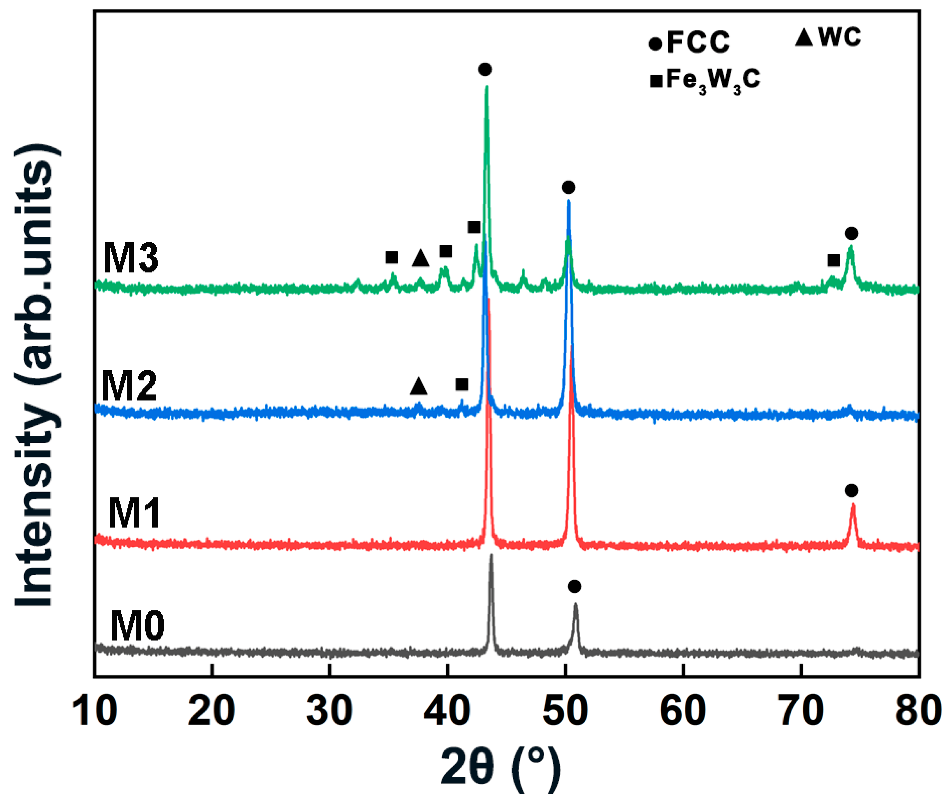
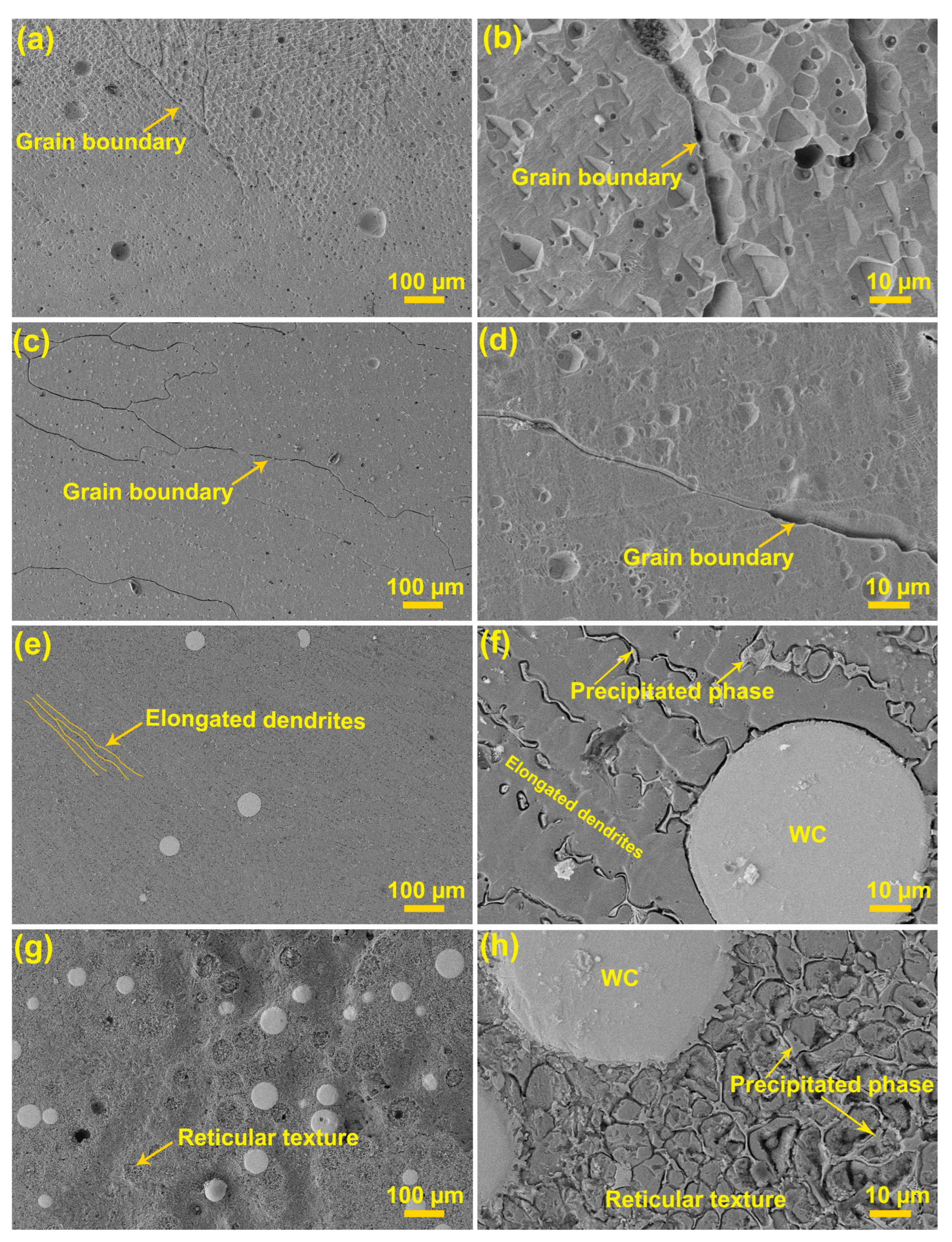
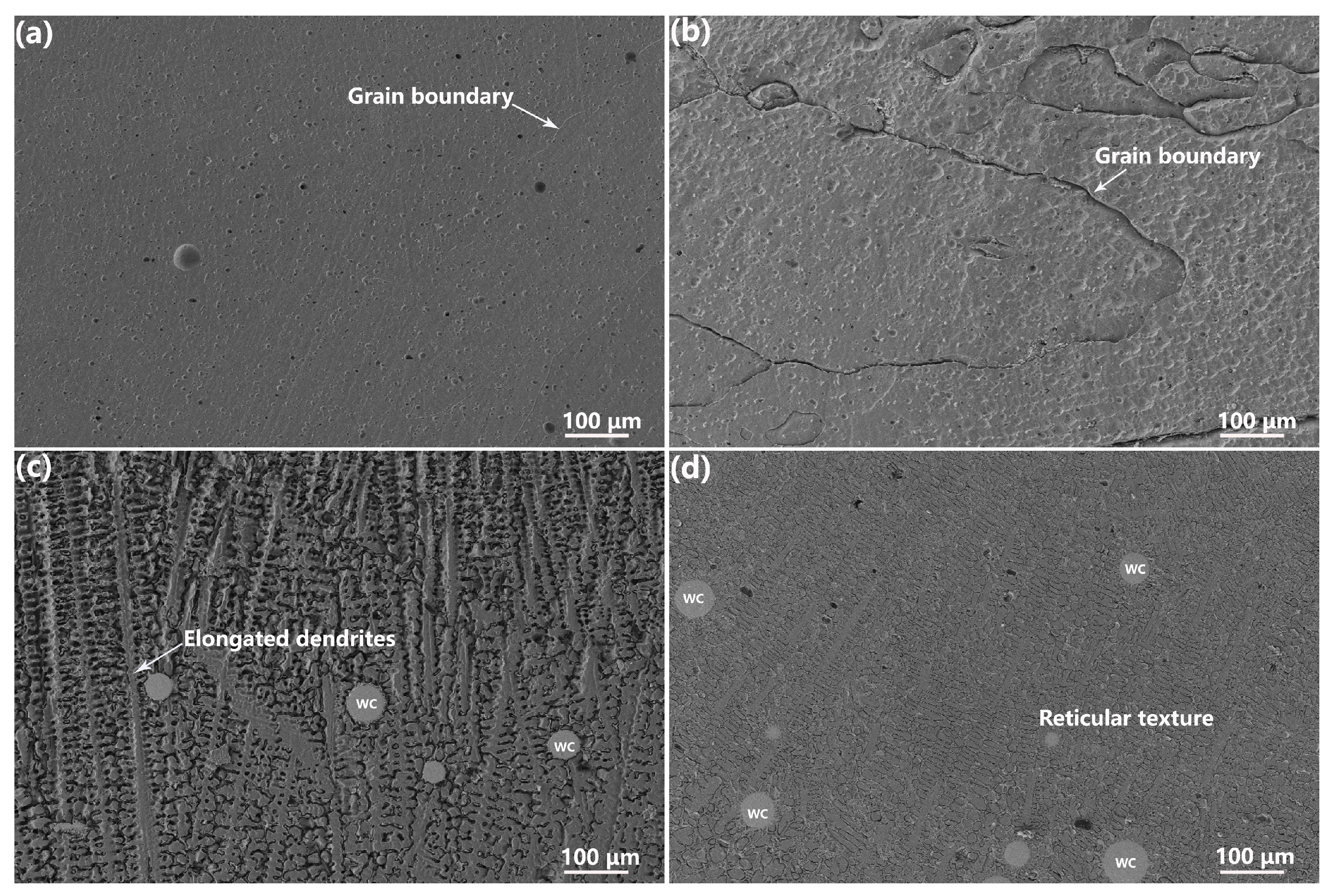
The decomposition of WC particles during the surfacing process induced the formation of massive carbides and eutectic carbides but also simultaneously triggered a significant refinement effect of grain size. These W and C atoms diffused into the matrix and thereby initiated the formation of supersaturated solid solutions.
(2)
The coating showed a consistent hardness enhancement with an increasing WC doping content due to a synergistic strengthening of the solid solution, second hard phase, and grain refinement. The hardness was 198.8 ± 15.6 HV for the coating without WC doping, but it increased to 222.3 ± 34.4 HV for the coating with 10% WC doping and 355.6 ± 51.6 HV for the coating with 20% WC doping, and it reached the highest value of 514.9 ± 48.1 HV for the coating with 40% WC doping.
(3)
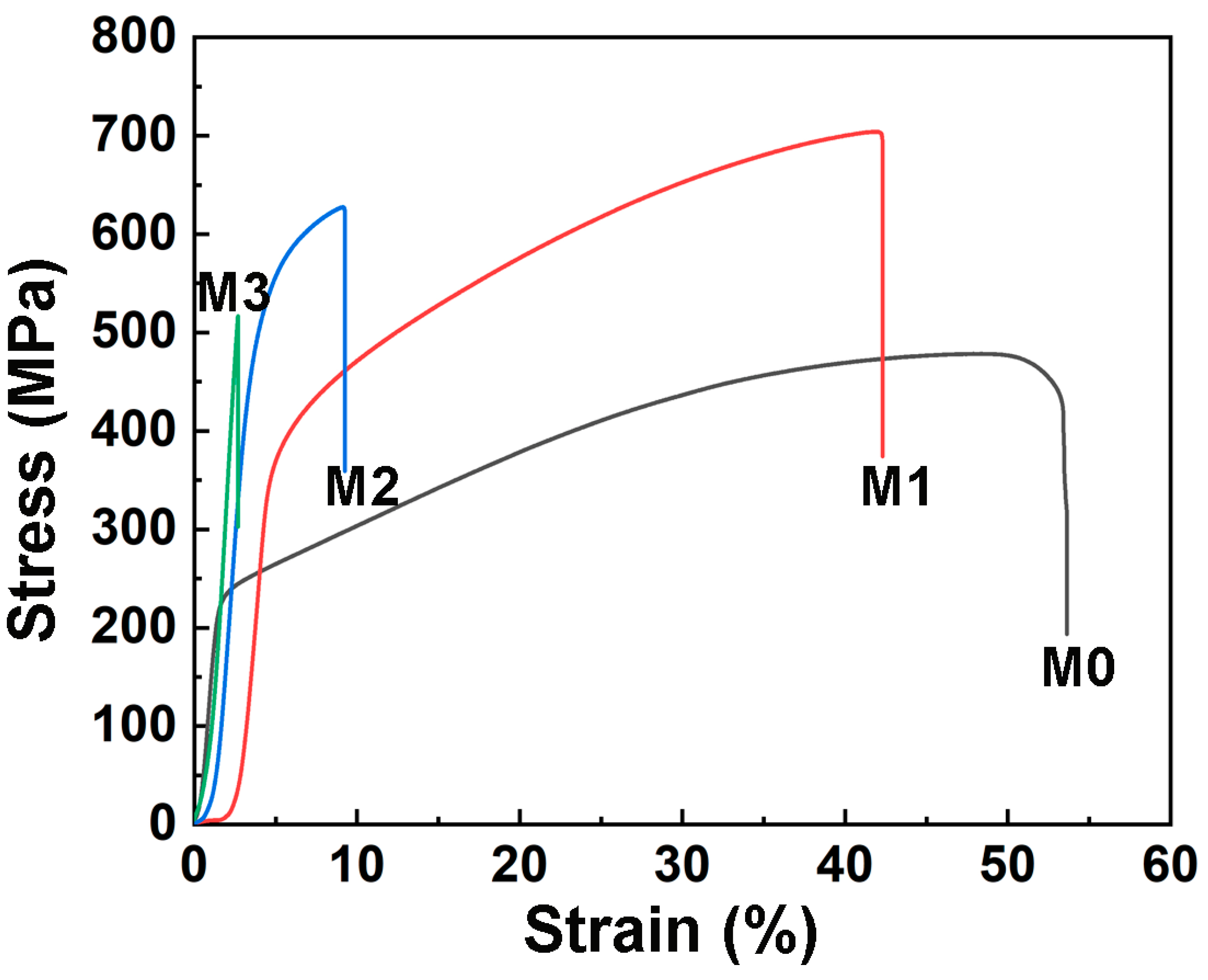
The supersaturated solid solutions, carbides, WC particles, and refined grains effectively reinforced the matrix alloy of the coating, leading to a substantial enhancement in yield strength with an increasing WC content. The yield strength was 225 MPa for the coating without WC doping, but it increased to 353 MPa for the coating with 10% WC doping and 454 MPa for the coating with 20% WC doping, and it reached the highest value of 457 MPa for the coating with 40% WC doping.
(4)
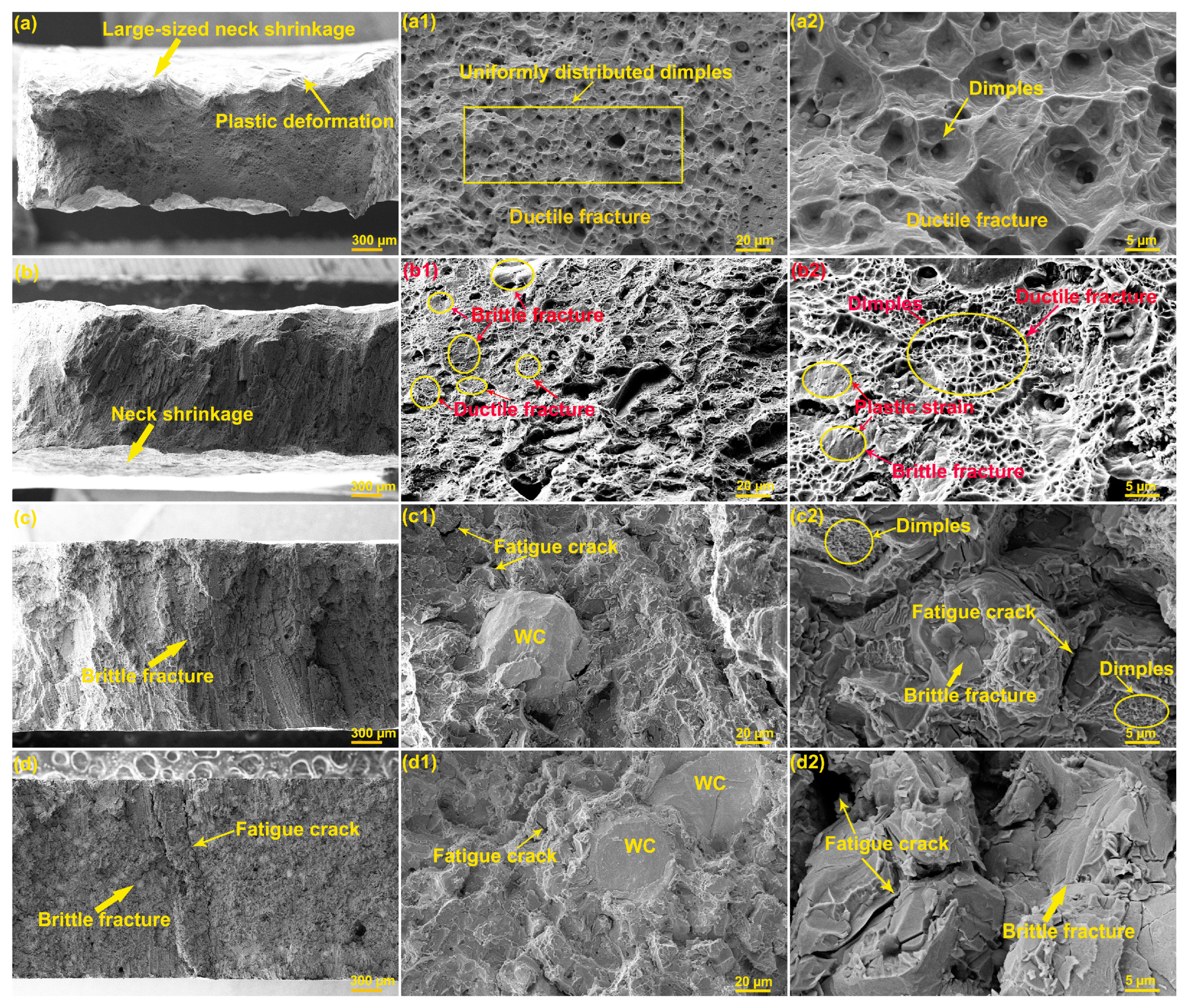
The inherent high brittleness of these supersaturated solid solutions and carbides greatly degraded the ductility of the matrix alloy. The strain was 53.7% for the coating without WC doping and it was 42.6% for the coating with 10% WC doping, but that rapidly decreased to 9.4% for the coating with 20% WC doping and reached the lowest value of 2.7% for the coating with 40% WC doping.
(5)
The coating with a 10% WC content demonstrated an exceptional balance between strength and toughness, showing the highest tensile strength value of 704 MPa.

Author Contributions

X.W., investigation, writing—original draft preparation; S.Z., investigation, methodology; F.Z., data curation, investigation; Z.W., conceptualization, writing—reviewing and editing; Z.X., conceptualization, writing—reviewing and editing. All authors have read and agreed to the published version of the manuscript.

Funding

The authors appreciate the financial support by the National Key Research and Development Program (No. 2018YFA0707305), Key R & D program of Shanxi Province (No. 202102050201001), Shanxi Key Research and Development Program (No. 202101120401008), Shanxi Youth Science Foundation Project (No. 201901D211291), 2023 Open R&D project of the Research Institute of Haian Taiyuan University of Technology (No. 2023HA-TYUTKFYF012), Graduate Education Innovation Project of Taiyuan University of Science and Technology (No. BY 2022005).

Institutional Review Board Statement

Not applicable.

Informed Consent Statement

Not applicable.

Data Availability Statement

Data will be made available on request.

Acknowledgments

We sincerely thank the Test Center of Anshan Mingjian for its tensile test technical support.

Conflicts of Interest

The authors declare no conflicts of interest.

References

  1. Xie, Z.; Guo, F.; Huang, X.; Li, K.; Chen, Q.; Chen, Y.; Gong, F. Understanding the anti-wear mechanism of SiCp/WE43 magnesium matrix composite. Vacuum 2020, 172, 109049. [Google Scholar] [CrossRef]
  2. Akbari, M.K.; Baharvandi, H.R.; Shirvanimoghaddam, K. Tensile and fracture behavior of nano/micro TiB2 particle reinforced casting A356 aluminum alloy composites. Mater. Des. 2015, 66, 150–161. [Google Scholar] [CrossRef]
  3. Tan, H.; Luo, Z.; Li, Y.; Yan, F.; Duan, R.; Huang, Y. Effect of strengthening particles on the dry sliding wear behavior of Al2O3-M7C3/Fe metal matrix composite coatings produced by laser cladding. Wear 2015, 324–325, 36–44. [Google Scholar] [CrossRef]
  4. Dai, Y.; Li, K.; Xiang, Q.; Ou, M.; Yang, F.; Liu, J. Microstructure and tribology behaviors of WC coating fabricated by surface mechanical composite strengthening. Appl. Surf. Sci. 2023, 619, 156759. [Google Scholar] [CrossRef]
  5. Wang, X.H.; Zhang, M.; Du, B.S.; Li, S. Microstructure and wear properties of laser clad (TiB2+TiC)/Fe composite coating. Surf. Rev. Lett. 2012, 19, 1250052. [Google Scholar] [CrossRef]
  6. Wei, M.; Yu, H.; Song, Z.; Yin, Y.; Zhou, X.; Wang, H.; Ji, X.; Li, X.; Shi, P.; Zhang, W. Microstructural evolution, mechanical properties and wear behavior of in-situ TiC-reinforced Ti matrix composite coating by induction cladding. Surf. Coat. Technol. 2021, 412, 127048. [Google Scholar] [CrossRef]
  7. Yin, Z.; Tao, S.; Zhou, X.; Ding, C. Tribological properties of plasma sprayed Al/Al2O3 composite coatings. Wear 2007, 263, 1430–1437. [Google Scholar] [CrossRef]
  8. Wu, P.; Du, H.M.; Chen, X.L.; Li, Z.Q.; Bai, H.L.; Jiang, E.Y. Influence of WC particle behavior on the wear resistance properties of Ni–WC composite coatings. Wear 2004, 257, 142–147. [Google Scholar] [CrossRef]
  9. Zhou, S.F.; Dai, X.Q. Laser induction hybrid rapid cladding of WC particles reinforced NiCrBSi composite coating. Appl. Surf. Sci. 2010, 256, 4708–4714. [Google Scholar] [CrossRef]
  10. He, L.; Tan, Y.F.; Wang, X.L.; Jing, Q.F.; Hong, X. Tribological properties of laser cladding TiB2 particles reinforced Ni-base alloy composite coatings on aluminum alloy. Rare Met. 2015, 34, 789–796. [Google Scholar] [CrossRef]
  11. Wei, H.; Feng, G.; Li, X.; Zhan, W.; Li, F.; Dai, Y.; Zou, J. Preparation and tribological properties of Cr-C reinforced Cu/graphite composites decomposed in situ by Cr2AlC. Tribol. Int. 2023, 189, 108911. [Google Scholar] [CrossRef]
  12. Du, M.; Dong, W.; Dong, L.; Li, X.; Wang, L. Nanostructure modification of titanium alloy to achieve ultra-high interfacial bond strength between titanium alloy and polyphenylene sulfide. J. Mater. Res. Technol. 2023, 26, 3383–3394. [Google Scholar] [CrossRef]
  13. Chung, K.H.; Hwang, Y.C. Bonding strengths of porcelain repair systems with various surface treatments. J. Prosthet. Dent. 1997, 78, 267–274. [Google Scholar] [CrossRef] [PubMed]
  14. Yang, T.; Zhao, Y.L.; Cao, B.X.; Kai, J.J.; Liu, C.T. Towards superior mechanical properties of hetero-structured high-entropy alloys via engineering multicomponent intermetallic nanoparticles. Scr. Mater. 2020, 183, 39–44. [Google Scholar] [CrossRef]
  15. Zhao, Y.L.; Yang, T.; Zhu, J.H.; Chen, D.; Yang, Y.; Hu, A.; Liu, C.T.; Kai, J.-J. Development of high-strength Co-free high-entropy alloys hardened by nanosized precipitates. Scr. Mater. 2018, 148, 51–55. [Google Scholar] [CrossRef]
  16. Chuang, M.H.; Tsai, M.H.; Wang, W.R.; Lin, S.J.; Yeh, J.W. Microstructure and wear behavior of AlxCo1.5CrFeNi1.5Tiy high-entropy alloys. Acta Mater. 2011, 59, 6308–6317. [Google Scholar] [CrossRef]
  17. Dai, C.; Zhao, T.; Du, C.; Liu, Z.; Zhang, D. Effect of molybdenum content on the microstructure and corrosion behavior of FeCoCrNiMox high-entropy alloys. J. Mater. Sci. Technol. 2020, 46, 64–73. [Google Scholar] [CrossRef]
  18. Zhou, S.; Liang, Y.J.; Zhu, Y.; Jian, R.; Wang, B.; Xue, Y.; Wang, L.; Wang, F. High entropy alloy: A promising matrix for high-performance tungsten heavy alloys. J. Alloys Compd. 2019, 777, 1184–1190. [Google Scholar] [CrossRef]
  19. Luo, W.; Liu, Y.; Shen, J. Effects of binders on the microstructures and mechanical properties of ultrafine WC-10% AlxCoCrCuFeNi composites by spark plasma sintering. J. Alloys Compd. 2019, 791, 540–549. [Google Scholar] [CrossRef]
  20. Peng, Y.B.; Zhang, W.; Li, T.C.; Zhang, M.Y.; Wang, L.; Song, Y.; Hu, S.H.; Hu, Y. Microstructures and mechanical properties of FeCoCrNi high entropy alloy/WC reinforcing particles composite coatings prepared by laser cladding and plasma cladding. Int. J. Refract. Met. Hard Mater. 2019, 84, 105044. [Google Scholar] [CrossRef]
  21. Peng, Y.; Zhang, W.; Li, T.; Zhang, M.; Liu, B.; Liu, Y.; Wang, L.; Hu, S. Effect of WC content on microstructures and mechanical properties of FeCoCrNi high-entropy alloy/WC composite coatings by plasma cladding. Surf. Coat. Technol. 2020, 385, 125326. [Google Scholar] [CrossRef]
  22. Xie, G.Z.; Song, X.L.; Zhang, D.J.; Wu, Y.P.; Lin, P.H. Microstructure and corrosion properties of thick WC composite coating formed by plasma cladding. Appl. Surf. Sci. 2010, 256, 6354–6358. [Google Scholar] [CrossRef]
  23. Zhou, P.L.; Xiao, D.H.; Zhou, P.F.; Yuan, T.C. Microstructure and properties of ultrafine grained AlCrFeCoNi/WC cemented carbides. Ceram. Int. 2018, 44, 17160–17166. [Google Scholar] [CrossRef]
  24. Huang, J.; He, J.; Li, Z.; Shen, L.; Chen, L.; Chang, F.; Tang, Q. Effect of WC Addition on Microstructure and Properties of Powder Metallurgy CoCrNi Medium Entropy Alloy. Mater. Today Commun. 2023, 36, 106435. [Google Scholar] [CrossRef]
  25. Adachi, S.; Yamaguchi, T.; Tanaka, K.; Nishimura, T.; Ueda, N. Effects of Solid-Solution Carbon and Eutectic Carbides in AISI 316L Steel-Based Tungsten Carbide Composites on Plasma Carburizing and Nitriding. Metals 2023, 13, 1350. [Google Scholar] [CrossRef]
  26. Lou, D.; Hellman, J.; Luhulima, D.; Liimatainen, J.; Lindroos, V.K. Interactions between tungsten carbide (WC) particulates and metal matrix in WC-reinforced composites. Mater. Sci. Eng. A 2003, 340, 155–162. [Google Scholar] [CrossRef]
  27. Cao, F.; Chen, C.; Wang, Z.; Muthuramalingam, T.; Anbuchezhiyan, G. Effects of silicon carbide and tungsten carbide in aluminium metal matrix composites. Silicon 2019, 11, 2625–2632. [Google Scholar] [CrossRef]
  28. Zhou, R.; Jiang, Y.; Lu, D. The effect of volume fraction of WC particles on erosion resistance of WC reinforced iron matrix surface composites. Wear 2003, 255, 134–138. [Google Scholar] [CrossRef]
  29. Pan, Y.; Liu, A.; Huang, L.; Du, Y.; Jin, Y.; Yang, X.; Zhang, J. Effects of metal binder content and carbide grain size on the microstructure and properties of SPS manufactured WC–Fe composites. J. Alloys Compd. 2019, 784, 519–526. [Google Scholar] [CrossRef]
  30. Hussain, S.W.; Mehmood, M.A.; Karim, M.R.A.; Godfrey, A.; Yaqoob, K. Microstructural evolution and mechanical characterization of a WC-reinforced CoCrFeNi HEA matrix composite. Sci. Rep. 2022, 12, 9822. [Google Scholar] [CrossRef] [PubMed]
  31. Ravikumar, K.; Kiran, K.; Sreebalaji, V.S. Characterization of mechanical properties of aluminium/tungsten carbide composites. Measurement 2017, 102, 142–149. [Google Scholar] [CrossRef]
  32. Harrison, N.J.; Todd, I.; Mumtaz, K. Reduction of micro-cracking in nickel superalloys processed by Selective Laser Melting: A fundamental alloy design approach. Acta Mater. 2015, 94, 59–68. [Google Scholar] [CrossRef]
Figure 1. The schematic diagram of the plasma cladding technique.
Coatings 14 00403 g001
Figure 2. SEM images of the FeCoCrNiMn HEA (a) and WC powders (b).
Coatings 14 00403 g002
Figure 3. Tensile sample size (a) and morphology (b).
Coatings 14 00403 g003
Figure 4. Macroscopic photographs of the fabricated coatings: (a) M0; (b) M1; (c) M2; (d) M3.
Coatings 14 00403 g004
Figure 5. XRD patterns of the fabricated composite coatings.
Coatings 14 00403 g005
Figure 6. Surface SEM images of the fabricated coatings: (a,b) M0; (c,d) M1; (e,f) M2; (g,h) M3.
Coatings 14 00403 g006
Figure 7. Local SEM image and EDS spectra of sample M3.
Coatings 14 00403 g007
Figure 8. Cross-sectional SEM images of the fabricated coatings: (a) M0; (b) M1; (c) M2; (d) M3.
Coatings 14 00403 g008
Figure 9. Vickers hardness of the fabricated composite coatings.
Coatings 14 00403 g009
Figure 10. Tensile curves of the fabricated composite coatings.
Coatings 14 00403 g010
Figure 11. Macroscopic photographs of the fabricated coatings after the tensile tests: (a) M0; (b) M1; (c) M2; (d) M3.
Coatings 14 00403 g011
Figure 12. Fracture images of the fabricated coatings: (aa2) M0; (bb2) M1; (cc2) M2; (dd2) M3.
Coatings 14 00403 g012
Table 1. Surfacing welding parameters for the composite coatings.
SamplePercentage of WC
(wt. %)
Welding Current
(A)
Swinging Arc Speed (mm/min)Thickness
(mm)
M001501704.0 ± 0.25
M1101501704.0 ± 0.25
M2201501704.0 ± 0.25
M3401501704.0 ± 0.25
Table 2. Stress–strain data of the fabricated composite coatings.
SamplesYield Strength (MPa)Tensile Strength (MPa)Strain (%)
M022547853.7
M135370442.6
M24546279.4
M34575172.7
Disclaimer/Publisher’s Note: The statements, opinions and data contained in all publications are solely those of the individual author(s) and contributor(s) and not of MDPI and/or the editor(s). MDPI and/or the editor(s) disclaim responsibility for any injury to people or property resulting from any ideas, methods, instructions or products referred to in the content.

