Communication

Influence of Interlayers on Adhesion Strength of TiN Film on Mg Alloy

1
Key Laboratory of Advanced Technologies of Materials, Ministry of Education, College of Medicine, Southwest Jiaotong University, Chengdu 610031, China
2
College of Physics and Engineering, Chengdu Normal University, Chengdu 611130, China
3
Sichuan Province International Science and Technology Cooperation Base of Functional Materials, School of Materials Science and Engineering, Southwest Jiaotong University, Chengdu 610031, China
4
School of Physical Science and Technology, Southwest Jiaotong University, Chengdu 610031, China
*
Author to whom correspondence should be addressed.
Coatings 2024, 14(1), 121; https://doi.org/10.3390/coatings14010121
Submission received: 20 December 2023 / Revised: 11 January 2024 / Accepted: 16 January 2024 / Published: 16 January 2024

Abstract

:
The wide application of Mg alloys has been restricted because of their poor corrosion and wear resistance. Titanium nitride ceramic films prepared via magnetron sputtering can improve the corrosion and wear resistance of Mg alloys. However, residual stress produced at the interface between the film and the Mg alloy substrate causes the TiN film to spall off and reduces its service life. One potential approach to mitigating residual stress involves enhancing the adhesive strength between the film and the substrate, thereby potentially extending the service life of the film. To increase the adhesion strength between the TiN film and the Mg alloy substrate, a Ti or Al interlayer was deposited on the Mg alloy by magnetron sputtering. Subsequently, the adhesion strengths of TiN/Ti and TiN/Al were determined under a single high shear force by scratch tests and were determined under multiple low shear forces by friction and wear tests. The results of scratch tests show that TiN with the Ti interlayer on the Mg alloy substrate has superior adhesion strength under a single high shear force. And the results of friction and wear tests show that both the TiN/Al and TiN/Ti films provided protection to the Mg alloy substrate against friction and wear, and TiN with the Ti interlayer on the Mg alloy substrate has superior adhesion strength under multiple low shear forces. This work can provide guidance for the selection of interlayers between Mg alloy substrates and hard ceramic films.

1. Introduction

The engineering applications of Mg alloy are highly promising because of its low density (1.74 g/cm3) and high specific strength (approximately 130 kN·m/kg) [1,2]. However, the poor corrosion and wear resistance of Mg alloys restricts their wide application [3]. Magnetron sputtering is an economical and effective method for improving the corrosion and wear resistance of Mg alloys [4,5]. Titanium nitride ceramic films prepared via magnetron sputtering exhibit good corrosion [6] and wear resistance [7]. However, because of the residual stress of TiN ceramic films prepared by magnetron sputtering, spalling or failure may occur when they are stored in a service environment, which affects their normal service performance and reduces their service life [8,9,10]. The reason for this phenomenon is the significant differences in the hardness [11], coefficient of thermal expansion (CTE) [12], and lattice spacing [13] of the substrate and film, resulting in a large amount of residual stress at the interface after film preparation. The TiN film tends to crack and spall, releasing residual stress. In general, an interlayer with good ductility can improve adhesion strength by mitigating the disparities in the properties between the film and the substrate. This serves to reduce the generation of residual stress or allows for the interlayer to absorb stress through its own plastic deformation [14]. Therefore, TiN films with interlayers on the substrates have attracted considerable attention in recent years.
Several researchers have introduced an element of the substrate into the interlayer to improve the adhesion strength between the film and substrate [15,16,17]. They believed that the interlayer with an element of the substrate could reduce the differences in the properties between the film and substrate, thereby reducing the generation of residual stress. To improve the adhesion between the TiN films and the 316 L substrate, an Fe2Ti interlayer was deposited, which improved the adhesion strength to 50 N [15]. A Co interlayer was used to improve the adhesion strength between the TiN films and the WC-Co substrate, and the highest critical load of approximately 84 N was obtained [16]. The Cr interlayer was found to increase the adhesion of the TiN film by a factor of four on a stainless-steel 410 substrate [17]. In addition, the a-Si:H interlayer could promote the formation of Si-Fe dangling bonds at the bonding layer and enhance the chemical affinity between the 304 substrate and the Diamond Like Carbon (DLC) film, thus enhancing adhesion [18]. Regarding Mg alloy substrates, limited research describing which interlayers can improve the adhesion of TiN has been conducted. Therefore, it is necessary to explore the effect of the interlayer on the adhesion of the TiN film to the Mg alloy surface.
A Ti interlayer is often used to improve the adhesion between TiN films and stainless steel [19]. This can reduce the differences in properties between TiN and the Mg alloy substrate, thereby reducing the generation of residual stress. On the other hand, a Ti interlayer can improve adhesion strength between TiN and the Mg alloy substrate by absorbing impact energy through the plastic deformation [20]. Additionally, Al has high solid solubility in Mg alloys [21] and can improve the adhesion between TiN and the Mg alloy substrate by enhancing the chemical affinity between the substrate and the interlayer. In this study, two different metals, Ti and Al, were selected as the interlayers. TiN films were prepared on the surfaces of the two different interlayers on a Mg alloy substrate using the same method. The effects of the interlayers on the adhesion and wear resistance of the films were investigated.

2. Experimental

2.1. Sample Preparation

The Mg alloy (ZM21) was cut into circles with a thickness of 2 mm and a diameter of φ10 mm by wire cutting. The samples were then ultrasonically degreased in acetone and cleaned in anhydrous ethanol. The surfaces of the samples were mechanically polished with SiC paper, from grade 240 to 3000, and subsequently polished with a 1 µ-particle-size alumina suspension.

2.2. Deposition Process

Figure 1 shows the schematic of the vacuum chamber for film deposition. The films were deposited in a vacuum deposition system using a grounded stainless-steel chamber, which is cylindrical shaped with a 500 mm diameter and 500 mm height. Four unbalanced magnetron plasma sources with a rectangular planar titanium target (135 × 170 mm2) were placed inside the vacuum chamber. The cathode of the high-power pulsed magnetron sputtering (HPPMS) device was powered by a pulsed power supply fabricated by Chengdu Pulsetech Electrical (HPS-450D, Chengdu, China). A 3 Ω resistor in the HPPMS power supply was provided to protect the power source from arcing and limiting the plasma current. The workpiece was installed on a substrate holder at a target-to-substrate distance of 80 mm. After the vacuum chamber was pumped to a base pressure of 2.0 × 10⁻³ Pa, the Ti target in the vacuum chamber was cleaned by DC magnetron sputtering (2 A) for 10 min, and the Al target was cleaned for 5 min. Subsequently, the substrate was cleaned by a glow discharge with Ar ions (3.6 Pa, applied DC bias voltage of −1500 V) for 40 min. All the interlayers and film were deposited by HPPMS with a DC substrate bias of −150 V for the Ti and Al interlayers and −50 V for the TiN film. A pulse length of 50 μs, a frequency of 200 Hz, a trigger voltage of 800 V, and an average target power of 1.4 kW were maintained for the deposition of the Al interlayer for 10 min. A pulse length of 200 μs, a frequency of 150 Hz, a trigger voltage of 800 V, and an average target power of 2.1 kW were maintained for the deposition of the Ti interlayer for 5 min and the TiN film for 15 min. The flow rate of Ar gas was 40 sccm for the interlayers, and the flow rates of N and Ar gas were 4 and 60 sccm, respectively, for the TiN film. The film thickness, measured using a surface profilometer, of TiN with the Ti interlayer was approximately 650 nm, whereas that of TiN with the Al interlayer was approximately 450 nm. The residual stress measured by the substrate curvature method for TiN with a Ti interlayer was approximately 3.58 GPa, and that of TiN with an Al interlayer was approximately 3.26 GPa.

2.3. Characterization Methods

A multifunctional material surface performance-testing machine (MFT-4000, Lanzhou, China) was used to evaluate the film adhesion. A pin-on-disk tribometer (TRB, CSM, Neuchâtel, Switzerland) was used to measure the wear resistance of the films. Scanning electron microscopy (SEM, JSM-7800F Prime, JEOL, Tokyo, Japan) was used to investigate the surface morphology, and energy dispersive spectrometry (EDS, Oxford X-Max 80, Abingdon, UK) was used to analyze the elemental composition. A focused ion beam (FIB, FEI Strata 400S, Hillsboro, OR, USA) and a transmission electron microscope (TEM, FEI Talos F200s Super-X, Hillsboro, OR, USA) were used to investigate the cross-sectional morphology.

3. Results and Discussion

3.1. Scratch Tests

Scratch tests were performed to test the adhesion of the films using an Al2O3 spherical indenter with a diameter of 4 mm. A progressive normal load from 0 to 50 N at a loading rate of 50 N/min was used in the first scratch test. The scratch length was 5 mm, and the scratch velocity was 5 mm/min. There were three critical loads in the scratch test: coating fracture (LC1), peeling off (LC2), and substrate exposure (LC3) [22].
Figure 2 shows the scratch morphologies of TiN/Al and TiN/Ti. Based on these images, it can be concluded that the TiN/Al substrate had been exposed when LC3 was approximately 6 N, and the TiN/Ti substrate had been exposed when LC3 was approximately 15 N. This indicates that TiN/Ti exhibits better adhesion than TiN/Al.
To determine which interface had been peeled off, the mapping images of the failure areas from TiN/Al and TiN/Ti after the pre-scratch test were obtained by EDS. The results of the EDS analysis are shown in Figure 3. These spectra revealed that the signal corresponding to the Mg alloy substrate in the failure areas of both TiN/Al and TiN/Ti was prominent. In contrast, the signals of other elements in the film were weak at the same position. The results of the EDS analyses of the failure areas indicated that both TiN/Al and TiN/Ti started peeling off at the interface between the Mg alloy substrate and the Ti or Al interlayer.
To further confirm the interface conditions, TEM samples were prepared in the failure area using an FIB. The interplanar spacings of the different structures from the powder diffraction file (PDF) are listed in Table 1, and the information on the crystal planes marked in the High-Resolution Transmission Electron Microscope (HRTEM) morphology are from Table 1.
The HRTEM morphology of the film and substrate interface in the failure area of the TiN/Al scratch is shown in Figure 4. As shown in Figure 4, a MgO layer is present between the Mg substrate and the Al interlayer. This indicates that oxidation of the Mg alloy substrate occurs during film deposition. As designed, the Al interlayer would contact the Mg alloy substrate and form chemical bonds with Mg. Thus, it would improve the adhesion strength of the Al interlayer and Mg alloy substrate. However, owing to the presence of the MgO layer revealed in the HRTEM morphology, the Al interlayer was not in contact with the Mg alloy substrate, and the Al interlayer barely formed any chemical bonds with the Mg alloy substrate.
The HRTEM morphology of the film and substrate interface of the TiN/Ti scratch failure area is shown in Figure 5. A MgO layer is also present between the Mg substrate and the Ti interlayer. In addition, an examination of Table 1 shows that the spacings of the different crystal planes of the MgO and TiN crystals are similar. Therefore, the crystal plane in the Ti interlayer with a spacing of approximately 2.47 Å could not be distinguished as either MgO or TiN.
The coefficient of thermal expansion (CTE), E-modulus (E), Poisson’s ratio (ν), and Vickers-hardness (HV) of the film, interlayer, and substrate at room temperature were obtained from a previous study [23]. These values are shown in Table 2. As shown in Table 2, the CTE of the Ti interlayer is more similar to those of TiN and MgO than that of the Al interlayer. And from Table 1, the interplanar spacing of the MgO structure is similar to TiN, and both the MgO structure and TiN structure are “NaCl structure”. And a Ti interlayer is often used to improve the adhesion between TiN films and stainless steel because it can minimize residual stress in the interface of film and substrate [19,24]. This indicates that the Ti interlayer can better reduce the generation of residual stress between TiN and MgO during deposition than the Al interlayer. Additionally, an interlayer with higher hardness could provide sufficient support for hard TiN [15], and the influence of this effect on adhesion is greater than the effects of residual stresses in TiN [25]. The HV of the Ti interlayer is higher than that of the Al interlayer. This indicates that Ti has higher hardness than Al and can provide more sufficient support than Al for the hard TiN on the surface of the soft metal Mg alloy substrate. In addition, the Al interlayer does not form chemical bonds with the Mg alloy substrate. Thus, the TiN/Ti film has better adhesion to the Mg alloy substrate than the TiN/Al film.

3.2. Friction and Wear

A pin-on-disk tribometer was used to measure the wear resistance of the films. Al2O3 spheres with a diameter of 6 mm were used as pins, and TiN/Al, TiN/Ti, and Mg alloy substrates were used as disks. The normal load selected was 0.5 N, and the radius and linear speed of wear were 3 mm and 18.9 mm·s−1, respectively. Friction and wear cycles were performed 3000 times. The morphology and cross-sectional profiles of the wear tracks of the different samples are shown in Figure 6. From Figure 6d, the width and depth of the wear tracks on the Mg alloy substrate were much larger than for TiN/Al and TiN/Ti films. This reveals that both the TiN/Al and TiN/Ti films provided protection to the Mg alloy substrate against friction and wear. Furthermore, as depicted in Figure 6b, the width of the wear tracks on TiN/Al film was approximately 110 μm, and a substantial amount of peeling was observed in the wear tracks. As shown in Figure 6c, the width of the wear tracks on TiN/Ti film was approximately 100 μm, and the film remained intact in the wear tracks. And from Figure 6d, the depths of the wear tracks on TiN/Al and TiN/Ti films were similar. Although the depths of the wear tracks on TiN/Al and TiN/Ti films were similar, the TiN/Al film had peeling in the wear tracks, and TiN/Ti remained intact in the wear tracks. This indicates that the TiN/Ti film provides better wear resistance than the TiN/Al film.
The variation in CoF for different samples with friction cycles is shown in Figure 7. The fluctuation in the CoF curves of the Mg alloy suggests the occurrence of stick-slip processes and abrasion by relatively hard (oxide) debris. The peak in the CoF curve of TiN/Al at approximately 2250 laps indicates that TiN/Al peeled off, and the Al2O3 ball countersurface started to rub against the Mg alloy substrate. The stabilization of the CoF curve of TiN/Ti reaffirmed that TiN/Ti film did not peel off in the wear tracks, as previously established. This also indicates that the TiN/Ti film exhibits better wear resistance than the TiN/Al film. The reason for this result might be the difference in adhesion between TiN/Ti and TiN/Al.

4. Conclusions

The effect of the TiN film on the adhesion and wear resistance of a Mg alloy substrate with Ti or Al as an interlayer was investigated. As intended, because of the oxidation of the Mg alloy during film deposition, neither interlayer came into contact with the Mg alloy substrate but rather with MgO. The main conclusions are summarized as follows:
  • The result of the scratch test indicated that TiN/Ti film had a higher critical load of failure than TiN/Al. The scratch tests applied a single high shear force to the film, and the results indicated that TiN with a Ti interlayer on the ZM21 Mg alloy substrate had a better adhesion strength under a single high shear force.
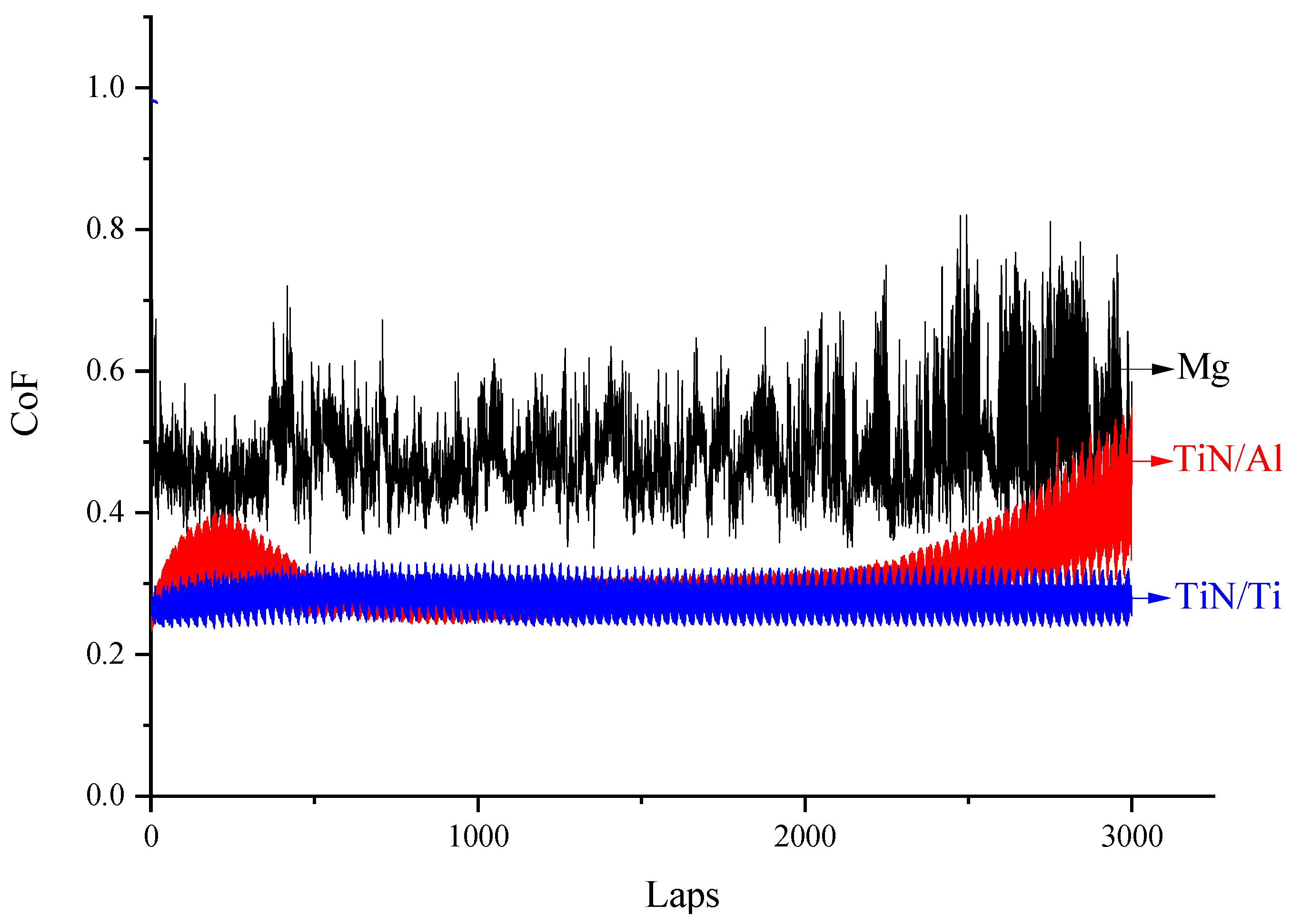
  • The friction and wear tests applied multiple low shear forces to the film, and the results indicated that TiN with a Ti interlayer on the ZM21 Mg alloy substrate had a better adhesion strength under multiple low shear forces.
  • Because the CTE of the Ti interlayer was more similar to that of TiN, Mg, and MgO than that of the Al interlayer, and the hardness of the Ti interlayer was larger than that of the Al interlayer, the TiN/Ti film exhibited better adhesion to the Mg alloy substrate than TiN/Al.

Author Contributions

Conceptualization, Y.L.; methodology, Y.L.; software, Y.L.; validation, Y.L., D.M. and H.L.; formal analysis, H.L.; investigation, H.L. and J.L.; resources, Y.L., D.X. and X.J.; data curation, Y.L.; writing—original draft preparation, H.L. and J.L.; writing—review and editing, Y.L. and D.M.; visualization, H.L. and J.L.; supervision, Y.L.; project administration, Y.L.; funding acquisition, Y.L., D.X. and X.J. All authors have read and agreed to the published version of the manuscript.

Funding

This work was supported by the National Natural Science Foundation of China (Grant number 51975564) and the Natural Science Foundation of Sichuan Province, China (Grant number 2022NSFSC0292).

Institutional Review Board Statement

Not applicable.

Informed Consent Statement

Not applicable.

Data Availability Statement

Data are contained within the article.

Conflicts of Interest

The authors declare no conflict of interest.

References

  1. Prasad, S.V.S.; Prasad, S.B.; Verma, K.; Mishra, R.K.; Kumar, V.; Singh, S. The role and significance of Magnesium in modern day research—A review. J. Magnes. Alloys 2022, 10, 1–61. [Google Scholar] [CrossRef]
  2. Liu, B.; Yang, J.; Zhang, X.; Yang, Q.; Zhang, J.; Li, X. Development and application of magnesium alloy parts for automotive OEMs: A review. J. Magnes. Alloys 2023, 11, 15–47. [Google Scholar] [CrossRef]
  3. Yang, S.; Zou, B.; Shen, J.; Cai, X.; Wang, Y.; Cao, X.; Zhu, L. Thermal shock behavior of YSZ thermal barrier coatings with a Ni-P/Al/Ni-P sandwich interlayer on AZ91D magnesium alloy substrate at 400 °C. Surf. Coat. Technol. 2019, 367, 278–287. [Google Scholar] [CrossRef]
  4. Wu, H.; Qasim, A.M.; Xiao, S.; Huang, Q.; Zhang, F.; Wu, Z.; Fu, R.K.Y.; Wu, G.; Chu, P.K. Magnetron-sputtered fluorocarbon polymeric film on magnesium for corrosion protection. Surf. Coat. Technol. 2018, 352, 437–444. [Google Scholar] [CrossRef]
  5. Surmeneva, M.A.; Surmenev, R.A. Microstructure characterization and corrosion behaviour of a nano-hydroxyapatite coating deposited on AZ31 magnesium alloy using radio frequency magnetron sputtering. Vacuum 2015, 117, 60–62. [Google Scholar] [CrossRef]
  6. Lin, L.; Tian, Y.; Yu, W.; Chen, S.; Chen, Y.; Chen, W. Corrosion and hardness characteristics of Ti/TiN-modified Ti6Al4V alloy in marine environment. Ceram. Int. 2022, 48, 34848–34854. [Google Scholar] [CrossRef]
  7. Sheng, L.; Xiao, Y.; Jiao, C.; Du, B.; Li, Y.; Wu, Z.; Shao, L. Influence of layer number on microstructure, mechanical properties and wear behavior of the TiN/Ti multilayer coatings fabricated by high-power magnetron sputtering deposition. J. Manuf. Process. 2021, 70, 529–542. [Google Scholar] [CrossRef]
  8. Liu, H.; Xu, Q.; Zhang, X.; Wang, C.; Tang, B. Residual stress analysis of TiN film fabricated by plasma immersion ion implantation and deposition process. Nucl. Instrum. Methods Phys. Res. Sect. B Beam Interact. Mater. At. 2013, 297, 1–6. [Google Scholar] [CrossRef]
  9. Cemin, F.; Abadias, G.; Minea, T.; Lundin, D. Tuning high power impulse magnetron sputtering discharge and substrate bias conditions to reduce the intrinsic stress of TiN thin films. Thin Solid Film. 2019, 688, 137335. [Google Scholar] [CrossRef]
  10. Li, H.; Sun, P.; Cheng, D.; Liu, Z. Effects of deposition temperature on structure, residual stress and corrosion behavior of Cr/TiN/Ti/TiN films. Ceram. Int. 2021, 47, 34909–34917. [Google Scholar] [CrossRef]
  11. Subramanian, B.; Jayachandran, M. Characterization of reactive magnetron sputtered nanocrystalline titanium nitride (TiN) thin films with brush plated Ni interlayer. J. Appl. Electrochem. 2007, 37, 1069–1075. [Google Scholar] [CrossRef]
  12. Chien, H.; Diaz-Jimenez, C.; Rohrer, G.S.; Ban, Z.; Prichard, P.; Liu, Y. The influence of residual thermal stresses on the mechanical properties of multilayer α-Al2O3/TiCxN1−x coatings on WC/Co cutting tools. Surf. Coat. Technol. 2013, 215, 119–126. [Google Scholar] [CrossRef]
  13. Moridi, A.; Ruan, H.; Zhang, L.C.; Liu, M. Residual stresses in thin film systems: Effects of lattice mismatch, thermal mismatch and interface dislocations. Int. J. Solids Struct. 2013, 50, 3562–3569. [Google Scholar] [CrossRef]
  14. Alat, E.; Motta, A.T.; Comstock, R.J.; Partezana, J.M.; Wolfe, D.E. Ceramic coating for corrosion (c3) resistance of nuclear fuel cladding. Surf. Coat. Technol. 2015, 281, 133–143. [Google Scholar] [CrossRef]
  15. Song, M.; Guo, J.; Yang, Y.; Geng, K.; Xiang, M.; Zhu, Q.; Hu, C.; Zhao, H. Fe2Ti interlayer for improved adhesion strength and corrosion resistance of TiN coating on stainless steel 316L. Appl. Surf. Sci. 2020, 504, 144483. [Google Scholar] [CrossRef]
  16. Hee Kwon, D.; Chang Kang, M.; Suk Kim, J.; Tae Ok, J.; Ho Kim, K. A comparative study on cutting performance of TiN-coated tungsten carbide cutting tool with a cobalt interlayer. Surf. Coat. Technol. 2005, 200, 1933–1938. [Google Scholar] [CrossRef]
  17. Li, D.; Guruvenket, S.; Hassani, S.; Bousser, E.; Azzi, M.; Szpunar, J.A.; Klemberg-Sapieha, J.E. Effect of Cr interlayer on the adhesion and corrosion enhancement of nanocomposite TiN-based coatings deposited on stainless steel 410. Thin Solid Film. 2011, 519, 3128–3134. [Google Scholar] [CrossRef]
  18. Wang, X.; Sui, X.; Zhang, S.; Yan, M.; Lu, Y.; Hao, J.; Liu, W. Impacts of the a-Si:H interlayer nanostructure on the adhesion of the thick DLC coatings prepared by PECVD. Appl. Surf. Sci. 2021, 565, 150539. [Google Scholar] [CrossRef]
  19. Jiang, C.L.; Zhu, H.L.; Shin, K.S.; Tang, Y.B. Influence of titanium interlayer thickness distribution on mechanical properties of Ti/TiN multilayer coatings. Thin Solid Film. 2017, 632, 97–105. [Google Scholar] [CrossRef]
  20. Xie, W.; Zhao, Y.; Liao, B.; Wang, S.; Zhang, S. Comparative tribological behavior of TiN monolayer and Ti/TiN multilayers on AZ31 magnesium alloys. Surf. Coat. Technol. 2022, 441, 128590. [Google Scholar] [CrossRef]
  21. Li, D.; Cui, Z.-q.; Yang, Q.-x.; Sun, B.; Sun, M.-h. Microstructure and property of friction stir welding joint of 7075Al and AZ31BMg. J. Shanghai Jiaotong Univ. (Sci.) 2012, 17, 679–683. [Google Scholar] [CrossRef]
  22. Lenz, B.; Hasselbruch, H.; Großmann, H.; Mehner, A. Application of CNN networks for an automatic determination of critical loads in scratch tests on a-C:H:W coatings. Surf. Coat. Technol. 2020, 393, 125764. [Google Scholar] [CrossRef]
  23. WebElements. The University of Sheffield and WebElements Ltd, UK. Copyright 1993–2023 Mark Winter. Available online: https://www.webelements.com/ (accessed on 5 December 2023).
  24. Yanfeng, W.; Zhengxian, L.; Haonan, W.; Jihong, D.; Changwei, Z. Effect of Multilayered Structure on Properties of Ti/TiN Coating. Rare Met. Mater. Eng. 2017, 46, 1219–1224. [Google Scholar] [CrossRef]
  25. Gerth, J.; Wiklund, U. The influence of metallic interlayers on the adhesion of PVD TiN coatings on high-speed steel. Wear 2008, 264, 885–892. [Google Scholar] [CrossRef]
Figure 1. The schematic of the vacuum chamber.
Coatings 14 00121 g001
Figure 2. Scratch morphology of (a) TiN/Al and (b) TiN/Ti.
Coatings 14 00121 g002
Figure 3. SEM/EDS analysis results of (a) TiN/Al and (b) TiN/Ti.
Coatings 14 00121 g003
Figure 4. HRTEM morphology of film/substrate interface in failure area of TiN/Al scratch.
Coatings 14 00121 g004
Figure 5. HRTEM morphology of film/substrate interface in failure area of TiN/Ti scratch.
Coatings 14 00121 g005
Figure 6. Morphology of wear of different samples: (a) Mg, (b) TiN/Al, (c) TiN/Ti, and (d) contours of wear.
Coatings 14 00121 g006
Figure 7. Variation in coefficient of friction (CoF) for different samples with friction cycles.
Coatings 14 00121 g007
Table 1. Interplanar spacing of different structures.
MgO
(PDF#75-0447)
Al
(PDF#01-1180)
Ti
(PDF#01-1197)
TiN
(PDF#87-0628)
2.44 Å2.33 Å2.56 Å2.45 Å
2.11 Å2.02 Å2.34 Å2.12 Å
1.49 Å1.43 Å2.24 Å1.50 Å
Table 2. Properties of the film, interlayer, and substrate [23].
CTE (×10−6/°C)E (GPa)νHV (MPa)
TiN9.35251--
Ti8.61160.32970
Al23.1700.35167
Mg8.2450.29-
MgO13.8310--
Disclaimer/Publisher’s Note: The statements, opinions and data contained in all publications are solely those of the individual author(s) and contributor(s) and not of MDPI and/or the editor(s). MDPI and/or the editor(s) disclaim responsibility for any injury to people or property resulting from any ideas, methods, instructions or products referred to in the content.

