Article

The Polishing of Inner Wall on Medical Device Hole by Shear Thickening Abrasive Flow

1
College of Mechanical Engineering, Zhejiang University of Technology, Hangzhou 310014, China
2
Key Laboratory of Special Purpose Equipment and Advanced Processing Technology, Zhejiang University of Technology, Hangzhou 310014, China
*
Author to whom correspondence should be addressed.
Coatings 2023, 13(9), 1492; https://doi.org/10.3390/coatings13091492
Submission received: 20 July 2023 / Revised: 16 August 2023 / Accepted: 17 August 2023 / Published: 24 August 2023
(This article belongs to the Special Issue Investigations and Applications in Advanced Materials Processing)

Abstract

:
To improve medical device hole inner wall quality and overcome issues of traditional abrasive flow methods—limited fluidity in small holes causing deformation due to high inner wall pressure, and slow processing with low viscosity abrasives—a new method called shear thickening abrasive flow polishing is suggested. It uses shear thickening fluid as the medium. By leveraging the Preston equation and fluid dynamics theory, this study establishes both an abrasive flow dynamics model and a material removal model for the shear thickening abrasive flow machining of small titanium alloy hole workpieces in medical instruments. Utilizing the COMSOL software, the flow field state of shear thickening fluid within small holes is examined under varying flow behavior indexes and flow velocities. The findings demonstrate that shear thickening fluid yields superior polishing effects compared to Newtonian fluid. Elevating the flow behavior indexes facilitates a higher material removal rate on the inner wall surface; however, excessively large flow behavior indexes diminish the uniformity of material removal, thereby hindering the attainment of a high-quality polished surface. Furthermore, excessively large flow behavior indexes can reduce fluidity and consequently lower the efficiency of the polishing process. Conversely, while maintaining a constant flow behavior index, increasing the flow velocity contributes to an enhanced material removal rate and improved polishing efficiency. Nevertheless, as the flow velocity rises, the uniformity of inner wall surface roughness diminishes, posing challenges in achieving a high-quality polished surface.

1. Introduction

In recent years, the medical industry has experienced robust growth, resulting in significant advancements in the medical device sector. Within this industry, hole structures are pervasive and find widespread application across various medical devices. Notably, slender small hole structures, such as the light guide port of endoscopes and urinary catheters, represent prominent examples of these devices.
The medical device industry necessitates meticulous attention to machining accuracy and stringent material properties when it comes to hole workpieces [1]. Consequently, titanium alloys, known for their exceptional attributes including high strength, robust corrosion resistance, and favorable biocompatibility, are commonly employed as the preferred metal materials in medical device manufacturing [2,3]. However, titanium alloys present challenges due to their poor machinability, elevated surface hardness, and arduous processing characteristics. Currently, hole processing in medical devices primarily involves two categories: traditional processing methods and non-traditional processing methods. Traditional approaches encompass conventional machining techniques such as drilling, punching, and grinding. Nonetheless, the relatively low thermal conductivity of titanium alloys exacerbates machining errors caused by heat accumulation during cutting, resulting in substantial deviations [4]. Non-traditional processing methods encompass ultrasonic processing, ion beam processing, laser processing, and similar techniques. Regrettably, these methods are hindered by issues such as exorbitant equipment costs and demanding technical prerequisites, impeding their widespread adoption [5].
Achieving superior surface quality necessitates additional grinding and polishing of titanium alloy holes in medical devices. Common methods employed include extrusion honing and the utilization of magnetic polishing machines. However, applying extrusion honing to small holes often leads to substantial mechanical deformation of the inner hole wall, while magnetic polishing is susceptible to surface damage and uneven material removal. Consequently, the medical industry faces a significant challenge in determining how to accomplish high-efficiency and precision machining of titanium alloy hole workpieces.
Abrasive flow polishing is a highly efficient method employed for surface processing. It exhibits exceptional fluidity, enabling effective conformational contact with the surface being processed [6,7,8]. Extensive research has been conducted on abrasive flow polishing, particularly regarding its application in polishing curved and intricate surfaces. These investigations encompass a wide range of topics, including molecular-level polishing mechanisms investigated through numerical simulations [9,10,11,12], and the enhancement of polishing effects through the utilization of various diversion structures. Numerous scholars have also explored the application of abrasive flow polishing in the context of small hole polishing, validating its feasibility through simulations and experimental studies. However, the conventional abrasive flow polishing method encounters challenges when applied to small hole workpieces composed of titanium alloy. This is primarily due to the high pressure exerted by the abrasive medium on the workpiece’s surface [13]. Moreover, soft abrasive flow polishing, characterized by low viscosity abrasive media, suffers from extended processing times and reduced efficiency. Often, additional auxiliary measures are necessary to enhance turbulence effects [14].
Therefore, this study explores the utilization of shear thickening fluid as an abrasive medium to achieve ultra-precision machining of workpiece surfaces through a “high-shear and low-pressure” approach, leveraging its rheological properties under shear stress. Shear thickening abrasive flow polishing has already demonstrated exceptional capabilities in achieving ultra-precision polishing of planar, spherical, cylindrical, and complex surfaces composed of crystals, metals, and ceramics [15]. Significant research efforts have been dedicated to investigating the influence of various processing parameters. For instance, Li et al. [16] employed shear thickening fluid for surface processing of black lithium tantalate substrates and analyzed the effects of polishing speed, diamond abrasive size, and diamond abrasive concentration. Similarly, Lyu et al. [17] investigated the application of a gel-type CeO2 abrasive in polishing quartz glass surfaces, successfully achieving remarkable surface roughness and flatness. However, limited research and practical applications exist concerning the polishing of inner wall surfaces using shear thickening fluid.
This paper addresses the issue of poor fluidity in traditional abrasive flow polishing when applied to small hole workpieces made of titanium alloy. This problem leads to surface deformation caused by high pressure on the inner wall. Additionally, the low viscosity of the initial abrasive medium used in soft abrasive flow polishing results in inadequate pressure on the inner wall, thereby diminishing the micro-cutting effect and prolonging the processing cycle. To overcome these challenges, a novel approach utilizing shear thickening fluid as the medium is introduced, referred to as shear thickening abrasive flow polishing. Furthermore, a mathematical model is developed to analyze the machining of shear thickening abrasive flow within small holes. Through numerical simulation, the study tracks the flow behavior of shear thickening abrasive flow in small holes with varying flow behavior indexes and flow velocities, while assessing their impact on the polishing effect of the inner wall surface. The findings of this analysis offer a reliable research foundation for the practical application of shear thickening abrasive flow in the machining of small titanium alloy holes in medical devices.

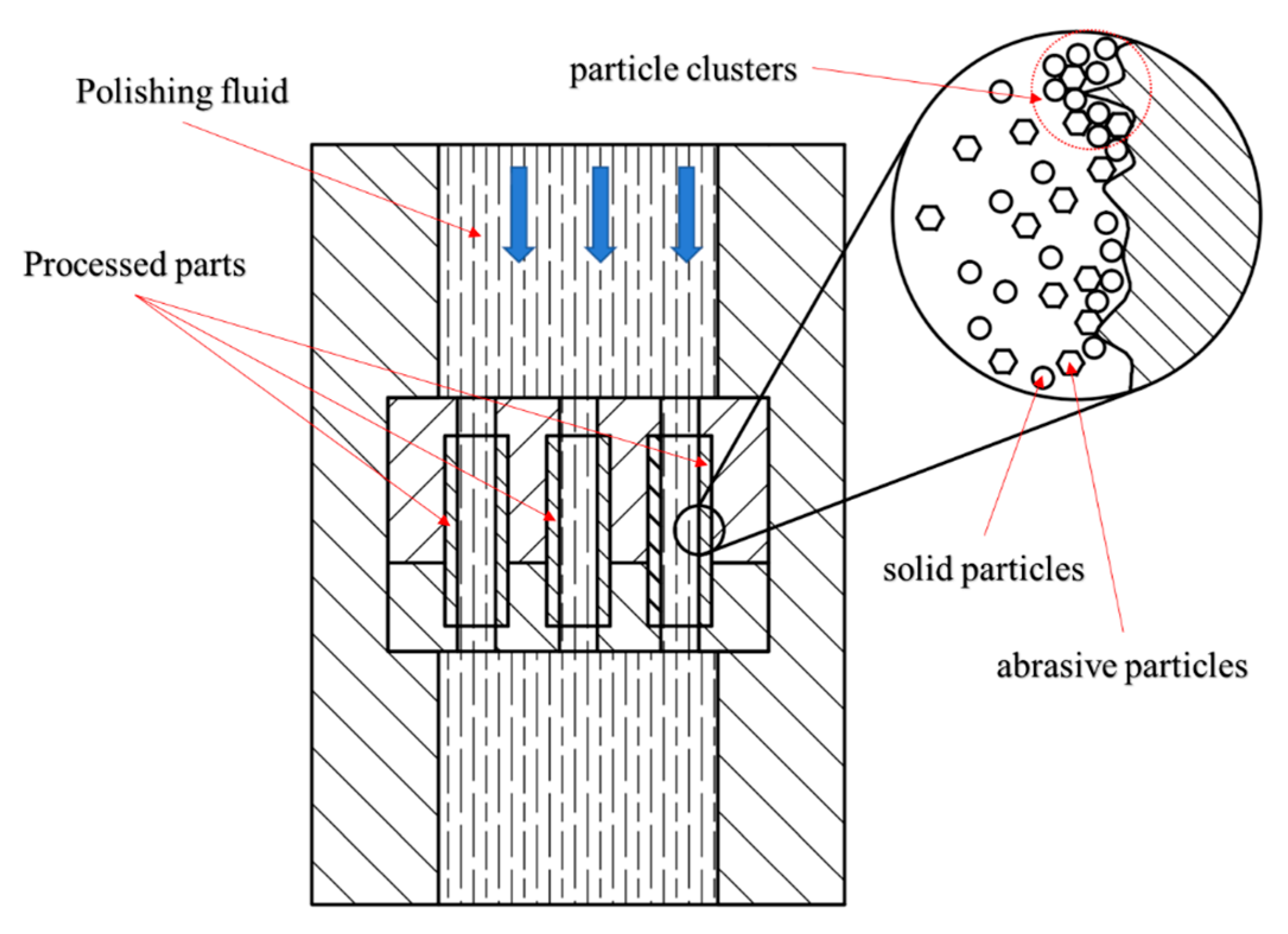
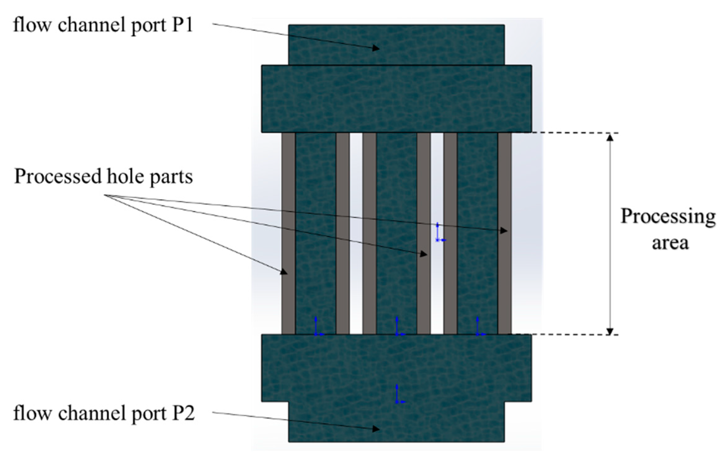
2. Machining Principle of Shear Thickening Abrasive Flow

Figure 1 illustrates the fundamental principle of shear thickening abrasive flow for machining the inner wall surface of small holes. Throughout the polishing process, the polishing fluid enters the processing area through the inlet. As the fluid encounters a sudden change in the flow channel, its velocity increases, leading to an acceleration in the shear rate. When the shear stress between the fluid and the inner wall of the processing area surpasses a specific threshold, the fluid undergoes shear thickening, resulting in a sharp rise in viscosity. This phenomenon causes the uniformly dispersed solid particles to form agglomerates, referred to as “particle clusters”, which include abrasive particles. As the polishing fluid continues to flow, numerous particle clusters interconnect to create a network of polymerized force chains, collectively acting as a micro-cutting agent on the inner wall surface. This process enables efficient material removal during the machining operation.

3. Mathematical Model of Shear Thickening Abrasive Flow

In this study, the shear thickening abrasive fluid, characterized by its non-Newtonian behavior and incompressibility, consists of a base fluid and loosely dispersed abrasive particles. To accurately simulate the distribution of the shear thickening abrasive flow field, a mixture multiphase flow model and a laminar model are employed in this research.

3.1. Constitutive Equation of Shear Thickening Abrasive Flow

The base fluid of shear thickening abrasive flow is a dilatant non-Newtonian fluid, wherein the viscosity exhibits an increase with rising shear rate. As a result, the behavior of the base fluid can be effectively captured by employing the constitutive equation of a non-Newtonian power-law fluid as follows:
η = K γ ˙ n 1
where η is dynamic viscosity, K is consistency coefficient, n is flow behavior index, and γ ˙ is shear rate. For shear thickening fluid, its flow behavior index n > 1 .

3.2. Laminar Model and Multiphase Flow Model

In fluid dynamics, the Reynolds number (Re) represents the ratio of inertial force to viscous force, and its expression can be expressed as
R e = ρ · v · d r e η
where ρ is fluid density, v is flow velocity, d r e is the characteristic length of the flow channel, and   η is dynamic viscosity.
The flow behavior and internal structure of a fluid are influenced by the ratio of inertial force to viscous force, known as the Reynolds number. Specifically, two distinct types of flow, laminar flow and turbulent flow, emerge depending on the Reynolds number. Extensive experimentation has revealed the following relationship between Reynolds number and fluid motion state: when Re > 4000, the fluid exhibits turbulent flow; when 2320 < Re < 4000, the fluid experiences an intermediate transition state between laminar and turbulent flow; and when Re < 2320, the fluid demonstrates laminar flow. Numerous studies and experiments have established that the Reynolds number of shear thickening abrasive fluid remains below 2320. Considering the solid–liquid two-phase nature of shear thickening abrasive flow, the commonly employed mixture model is suitable for simulating the dispersed solid particles or bubbles in the liquid phase. The mixture model facilitates the incorporation of momentum contributions from the dispersed phase and accommodates any number of dispersed phases. It offers improved computational accuracy and reduced computational cost compared to the Euler–Euler model, particularly when dealing with low volume fractions. Given the simulation requirements of this study, the laminar model and mixture model are selected as the simulation models. The mathematical expression for the laminar model is as follows:
u t + u · u = 1 ρ p + μ 2 u + F
ρ · u = 0
where u is the velocity vector of a fluid in a flow field, ρ is fluid density, F is volume force, and p is the pressure on a micro-element in the fluid.
The continuity equation of mixture multiphase flow model is expressed as
t ρ m + ρ m v m = 0
v m = k = 1 n α k ρ k v k ρ m
ρ m = k = 1 N α k ρ k
The momentum equation is expressed as
t ρ m v m + ρ m v m v m = p + μ m v m + v m T + ρ m g + F
k = 1 N α k ρ k v d r , k v d r , k
μ m = k = 1 N α k μ k
v d r , k = v k v m
where v m is average mass velocity, ρ m is the density of mixture, N is number of phases, α k is the volume fraction of each phase, μ m is the dynamic viscosity of mixture, and v d r , k is the drift speed of each phase.
Since the mixture fluid object studied in this paper is shear thickening fluid, Equation (1) describing the power law model of shear thickening fluid is used to replace Equation (9) in the original mixture multiphase flow mode.

3.3. Material Removal Model of Shear Thickening Abrasive Flow

The flow of shear thickening abrasive fluid within the inner wall of the workpiece, occurring at a specific relative velocity, induces the shear thickening phenomenon through interaction with the inner wall. This results in a non-linear augmentation of viscosity, rendering the conventional Preston equation (Equation (11)) inadequate for accurately elucidating the mechanism of material removal. Consequently, there arises a need to construct a material removal model for shear thickening abrasive flow within the inner wall of the circular hole, thereby furnishing a theoretical framework to facilitate future investigations.
M M R = k 0 p v
where k 0 is the coefficient of Preston equation; it is related to the characteristics of abrasive particles, the interaction between abrasive particles and the surface of workpiece, and the material properties of workpiece. When the process conditions are determined, k 0 is constant, p is the instantaneous pressure of the contact point between the workpiece surface and the fluid, and v is the instantaneous velocity of contact point between workpiece surface and fluid.
Initially, the shear thickening abrasive fluid is assumed to exhibit a consistent flow within the hole, and the pressure that propels the abrasive particles to impinge upon the wall surface can be approximated as the dynamic pressure of the fluid. In this context, the effect of gravitational forces can be disregarded, and the fluid’s distribution in the polished inner wall closely resembles pipe flow. Hence, by employing the flow equation of viscous fluid in a pipe, the constitutive equation of a power-law fluid is substituted into the flow equation, thereby yielding the fluid’s flow equation within the workpiece hole [18].
Q = π n 3 n + 1 p 2 K L 1 n R 3 n + 1 n
where Q is the flow of fluid in the workpiece hole, p is the pressure difference between the inlet and outlet of the inner hole of workpiece, L is the length of the workpiece, and R is the inner hole radius of the workpiece.
The pressure drop calculation formula of the fluid in the hole can be obtained by transforming the flow equation of Equation (12).
p = Q n 1 + 3 n π n n 2 K L R 1 + 3 n
It can be seen from Equation (13) that when the polishing fluid flows unidirectionally through the inner hole of the workpiece, the distance along the flow direction increases, and the fluid dynamic pressure decreases. Hence, while accounting for two-way cyclic processing and the outlet pressure ( p 0 ) of the workpiece’s inner hole, the symmetry of the flow channel allows the average dynamic pressure of the fluid at a specific wall point to be expressed as
p = U n 1 + 3 n n n K L R 1 + n + p 0
where U is the velocity of the fluid in the hole of the workpiece.
Upon contact of the shear thickening abrasive fluid with the inner wall of the hole at a designated relative velocity, the fluid’s viscosity escalates in direct correlation with the shear rate. This increase in viscosity predominantly manifests within the shear elastic layer adjacent to the object’s wall surface. The velocity of the abrasive particles, encapsulated by the surrounding polishing fluid within the shear elastic layer and possessing a specific particle size, can be reasonably approximated as [19]:
v = α d δ U = k 1 U
where d is abrasive size, α is the correlation coefficient of incident angle of abrasive, δ is the thickness of the shear elastic layer; in models with small fluid gaps, it can be approximated as a constant value k 1 .
Substituting Equations (14) and (15) into Equation (11), the material removal model of shear thickening abrasive flow in hole can be obtained:
M M R = k U n + 1 1 + 3 n n n K L R 1 + n + U p 0
where k 0 · k 1   is replaced by k , U is the velocity of the fluid in the hole of the workpiece, n is the flow behavior index, K is the consistency coefficient, R is the inner hole radius of the workpiece, L is the length of the workpiece, and p 0 is the outlet pressure, which is generally considered atmospheric pressure.
Based on the material removal model presented in Equation (16) for the shear thickening abrasive flow on the inner wall of the hole, it can be deduced that the rate of material removal is influenced by both pressure and flow velocity. Notably, pressure is not only contingent upon flow velocity but also closely associated with the viscosity characteristics of the fluid. By changing the flow behavior index “n” linked to fluid viscosity, the pressure curve in Figure 2 varies (notably when n = 1, indicating a Newtonian fluid). Figure 2 shows that at a consistent flow velocity, fluid pressure significantly surpasses that of n = 1 when n is greater than 1. This suggests that shear thickening fluid (n > 1) can achieve a faster material removal rate for inner hole wall processing compared to Newtonian fluid. Simultaneously, as the value of n increases, both pressure and material removal rate exhibit exponential growth. This implies that an augmentation in fluid viscosity, stemming from an intensified shear thickening effect resulting from higher n values, can yield superior polishing effects. However, when n surpasses 1.6, the fluid pressure exerted on the inner hole wall can easily exceed the MPa threshold. Excessive pressure compels the abrasive particles to forcefully interact with the wall surface, resulting in irregular pitting morphology and a subsequent decline in polishing efficacy. Moreover, for delicate titanium alloys, excessive pressure has the potential to induce deformation of the hole and cause damage to the workpiece.
Based on the established material removal model in this study, a consistent flow behavior index (where K = 0.05) is maintained. To examine the material removal rate within the central region of the hole, the flow velocity (U) is varied, and the resulting change in the material removal rate is plotted in the form of a trend curve shown in Figure 3. The analysis of Figure 3 reveals that as the flow velocity, U, increases, the material removal rate exhibits a rising trend following a power function. This observation indicates that, under the condition of a constant flow behavior index, augmenting the flow velocity, U, can enhance the material removal rate and improve the processing quality and efficiency of the inner hole of the workpiece.

4. Simulation and Results Discussion

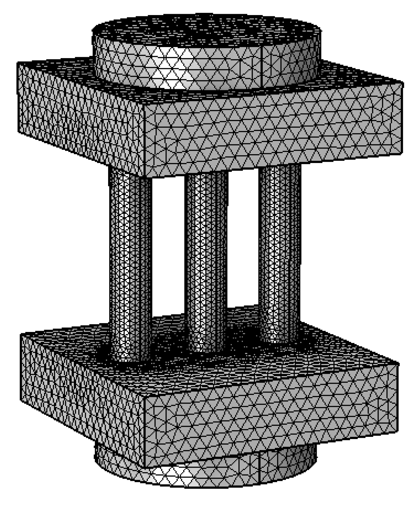
4.1. Model Development

This study focuses on the computational analysis of shear thickening abrasive flow machining on a small titanium alloy hole workpiece, in which the simulation can provide further understanding than experiments [20,21]. The computational domain consists of the processing region and the two ends of the flow channel. To investigate the machining effects, a typical small titanium alloy hole component with an inner diameter of 3 mm, wall thickness of 1 mm, and length of 15 mm was chosen as the target part for machining. The simulation calculations were performed using the COMSOL 5.6 software platform, utilizing the CFD module to enable three-dimensional entity simulations.
Initially, the software imports the solid model, and each component of the model is defined according to the specifications depicted in Figure 4. The abrasive flow enters through the flow channel inlet, denoted as P1, and exits through the flow channel outlet, designated as P2, after passing through the processing region. The cylindrical surface within the processing area represents the surface to be machined, while the remaining components form the primary structure of the flow channel. Subsequently, a free tetrahedral meshing technique is employed to discretize the entire flow channel, with the element size calibrated based on fluid dynamics considerations. To enhance computational accuracy, the mesh is refined specifically on the surface of the processing area. The resulting mesh division of the overall flow channel model is presented in Figure 5.
Based on the previous analysis, the shear thickening abrasive flow can be categorized as a solid–liquid two-phase flow. Consequently, in this study, the mixture–laminar flow model was selected as the multiphase flow simulation model. In defining the fundamental properties of the mixture, the continuous phase represents a customized abrasive medium fluid. The continuous phase exhibits a density ( ρ c ) of 1500 kg/m3 and a dynamic viscosity ( μ c ) of 1.01 × 10⁻³ Pa · s. On the other hand, the dispersed phase consists of SiC particles with a density ( ρ d ) of 3170 kg/m3 and a particle diameter ( d d ) of 10 μm. For the viscosity model of the mixture, a user-defined interface was chosen, and the mixture viscosity ( μ m ) is determined by the constitutive equation of a non-Newtonian power-law fluid, as described in Equation (1). To facilitate research and calculations, the consistency coefficient (K) is set at 0.05 Pa · s. The flow behavior index (n) and the inlet velocity (v) are established as global variable parameters. Depending on specific simulation requirements, either velocity inlet or pressure inlet conditions are selected as the boundary condition for the mixture inlet. The essential simulation parameters are presented in Table 1. By varying the flow behavior index (n) and the inlet velocity (v), simulations are conducted to investigate the polishing effects of shear thickening abrasive flow on small titanium alloy holes under different flow behavior indices and inlet velocities.

4.2. Results and Discussion

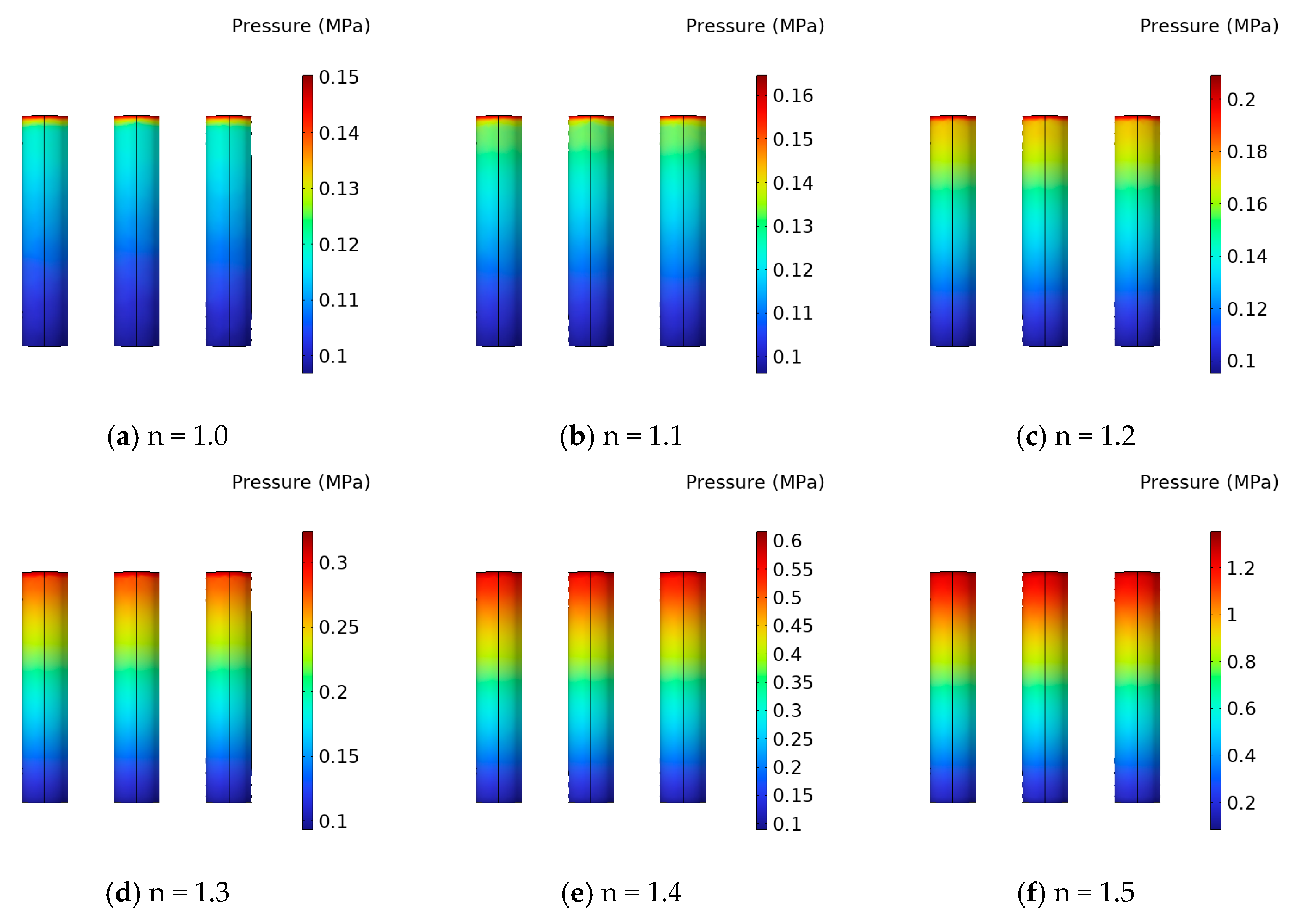
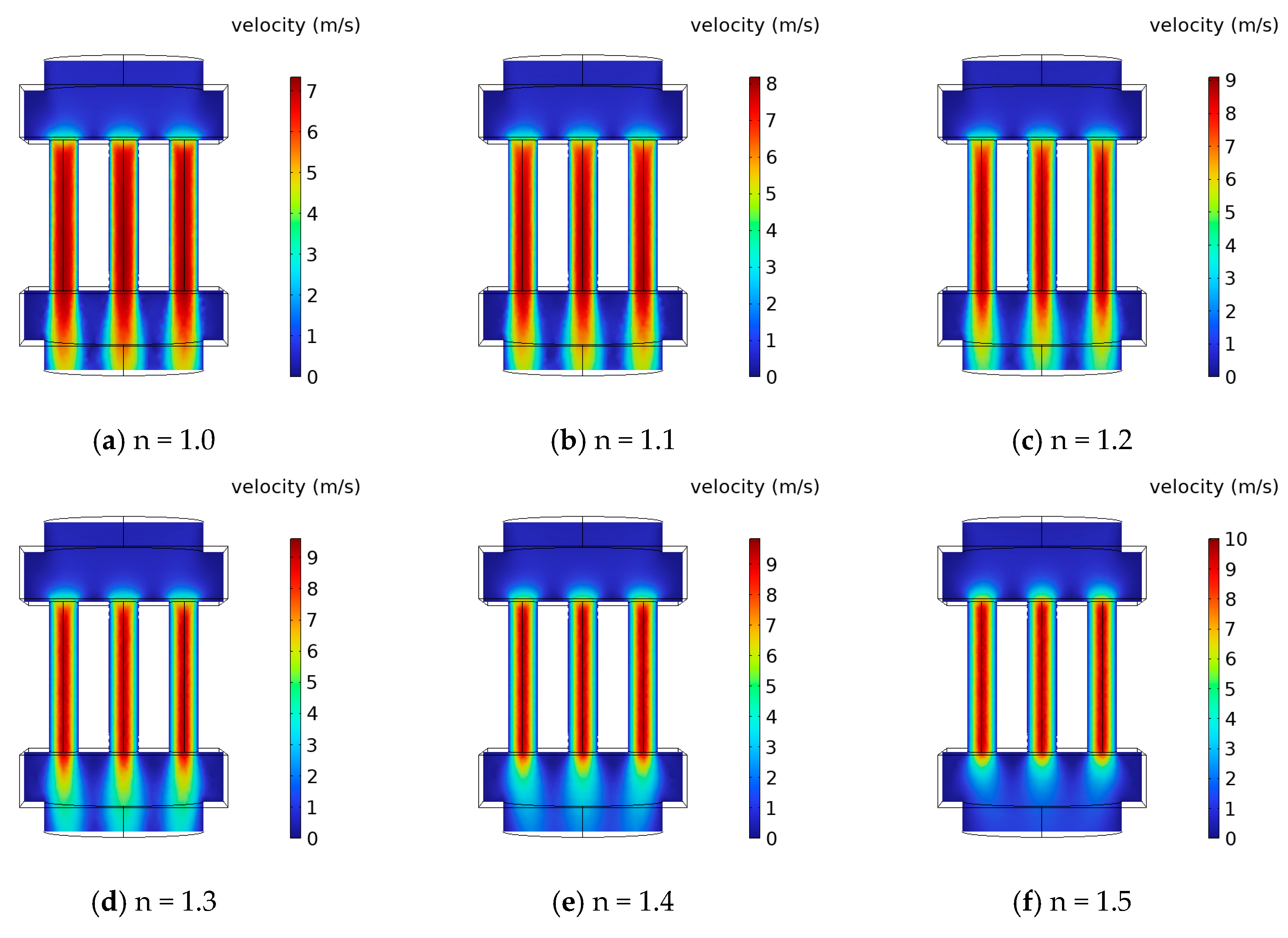
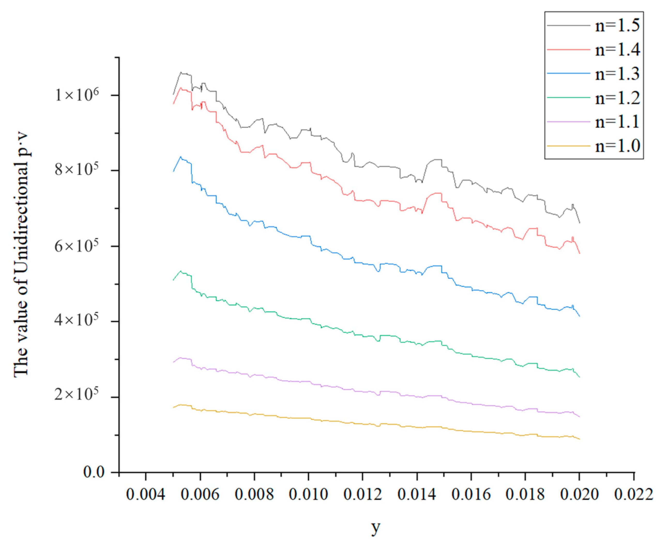
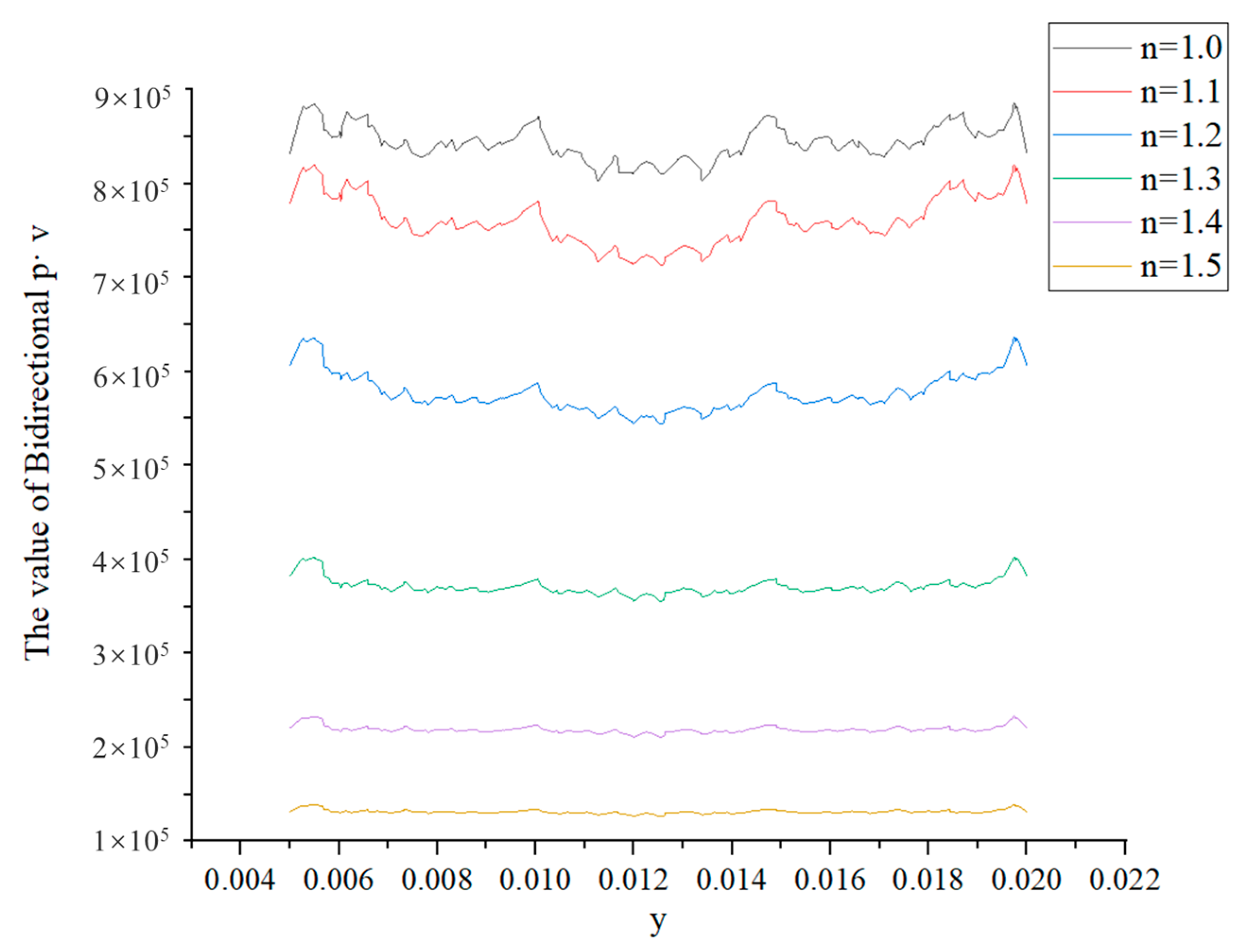
4.2.1. Effect of Flow Behavior Index on the Polishing Process

To investigate the impact of various flow behavior indices on the polishing effectiveness, the initial mixture inlet boundary condition (referred to as “boundary condition of inlet 1”) was chosen as the inlet velocity for simulation purposes. Under identical inlet velocities, the distribution of the pressure field in shear thickening polishing fluid exhibits remarkable similarity across different groups with distinct flow behavior indices, as depicted in Figure 6. During the unidirectional machining process, the polishing fluid traverses the machining area from the inlet to the outlet. As the fluid travels further along the flow direction, the pressure gradually decreases in a linear fashion, ultimately approaching the standard atmospheric pressure at the outlet. Notably, an observable trend emerges whereby an augmented flow behavior index corresponds to a substantial increase in the pressure exerted by the polishing fluid on the surface of the machining area.
Figure 7 presents the velocity distribution within the flow channel section under varying flow behavior indices while maintaining a constant inlet velocity. The figure illustrates that as the flow behavior index increases, the velocity field distribution gradually converges inward toward the processing area, and the fluid flow within the hole transitions towards a fully developed flow akin to pipe flow. Furthermore, an increase in the flow behavior index corresponds to an elevation in the maximum flow velocity at the center of the flow channel within the processing area, ranging from 7 m/s to 10 m/s. This behavior can be attributed to the heightened dynamic viscosity of the polishing fluid on the inner wall surface as the flow behavior index rises at the same shear rate. Consequently, when the viscosity reaches a certain threshold, it creates a boundary layer effect on the inner wall surface, constricting the inlet area available for the fluid. Consequently, the fluid outside the hole effectively flows into a smaller inner diameter hole, resulting in an amplified flow velocity at the center of the flow channel within the processing area.
In accordance with the material removal equation, the quantity of material removed is directly influenced by the product of the pressure exerted on the workpiece and the relative velocity of the abrasive. For flow field analysis, the inner side of the simulated model’s processing area’s outer boundary was extracted. This extraction involves multiplying the pressure line matrix and the velocity line matrix within any cross section, yielding a relative representation of the material removal rate at different positions, as depicted in Figure 8. Figure 8 illustrates the variations in the p·v line matrix throughout the unidirectional machining process of abrasive flow. As the fluid flows, the p·v value gradually diminishes due to declining pressure, accompanied by noticeable fluctuations in the velocity of the abrasive flow, exhibiting periodic rises and falls.
To account for the practical scenario of bidirectional abrasive flow processing, wherein the flow travels from channel P1 to channel P2 and then back from channel P2 to channel P1, the changes in the p·v line matrix during bidirectional processing were analyzed and obtained, as depicted in Figure 9. From Figure 9, it is evident that the bidirectional p·v value generally maintains a stable level with localized fluctuations. As the flow behavior index increases, the bidirectional p·v value exhibits an increment, albeit accompanied by an intensified degree of fluctuation. This observation indicates that an increased flow behavior index promotes higher material removal rates on the inner wall surface. However, an excessively large flow behavior index can lead to reduced consistency in material removal, consequently impeding the attainment of high-quality polished surfaces. Moreover, due to the unstable and insufficient expansion of the abrasive flow at the inlet and outlet, there exists a region characterized by more pronounced fluctuations in the p·v value. Consequently, in practical machining processes, the incorporation of inlet and outlet drainage sections can be considered to enhance the uniformity of material removal.
In practice, as the viscosity of shear thickening fluid increases with the flow, maintaining a consistently high level of fluidity similar to Newtonian fluids becomes challenging due to limitations imposed by the external power source. Consequently, when considering the impact of the flow behavior index on the polishing effectiveness, the fluidity of the fluid becomes an important factor to consider within the confines of the available power source. Optimal fluidity facilitates the efficient removal of material from the inner wall surface and the associated fluid through the flow field’s flow potential. This process enables the attainment of superior surface processing quality and enhances overall processing efficiency. To better investigate the influence of an increased flow behavior index on the fluidity of the polishing fluid within the hole, a control group (denoted as group “a”) was established as the reference. Additionally, an inlet pressure of 0.1 MPa was selected as the initial mixture’s inlet boundary condition (referred to as “boundary condition of inlet 2”). The simulation outcomes are depicted in Figure 10.
Figure 10 reveals that, when subjected to identical inlet pressure conditions, the variations in velocity distribution of shear thickening polishing fluid among different flow behavior index groups align closely with the trends observed earlier under the same inlet velocity conditions. In cases where the flow behavior index is low, the fluid’s behavior is primarily governed by inertial forces. However, as the flow behavior index increases, the velocity field distribution across the entire flow channel gradually converges towards the processing area. Remarkably, when the flow behavior index exceeds 1.3, the velocity field distribution within the flow channel undergoes minimal further alterations.
The key distinction lies in the consistent initial pressure condition, which causes an increase in the dynamic viscosity of the fluid due to the rising flow behavior index. This viscosity-related change directly impacts the fluid flow, primarily manifested in a significant attenuation of the flow velocity. Specifically, the maximum flow velocity at the center of the flow channel experiences a direct reduction from 9 m/s (as observed in the control group, denoted as group “a”) to 1.8 m/s when the flow behavior index reaches 1.5. This outcome signifies that an excessively large flow behavior index results in heightened viscosity, thereby impairing fluid flow within the hole. Consequently, the fluid may accumulate on the wall surface, impeding the effective removal of cutting waste through fluid flow. Such circumstances are unfavorable for achieving optimal polishing outcomes on the inner hole wall.

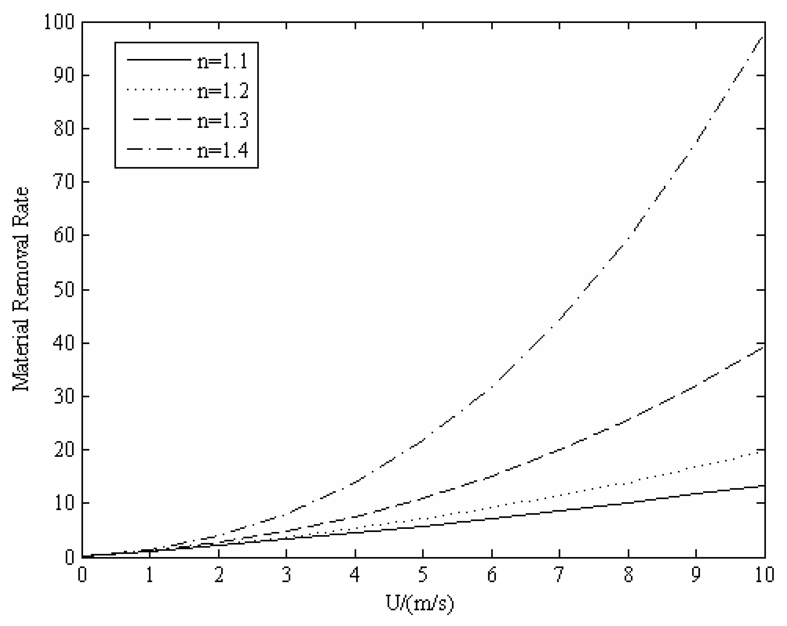
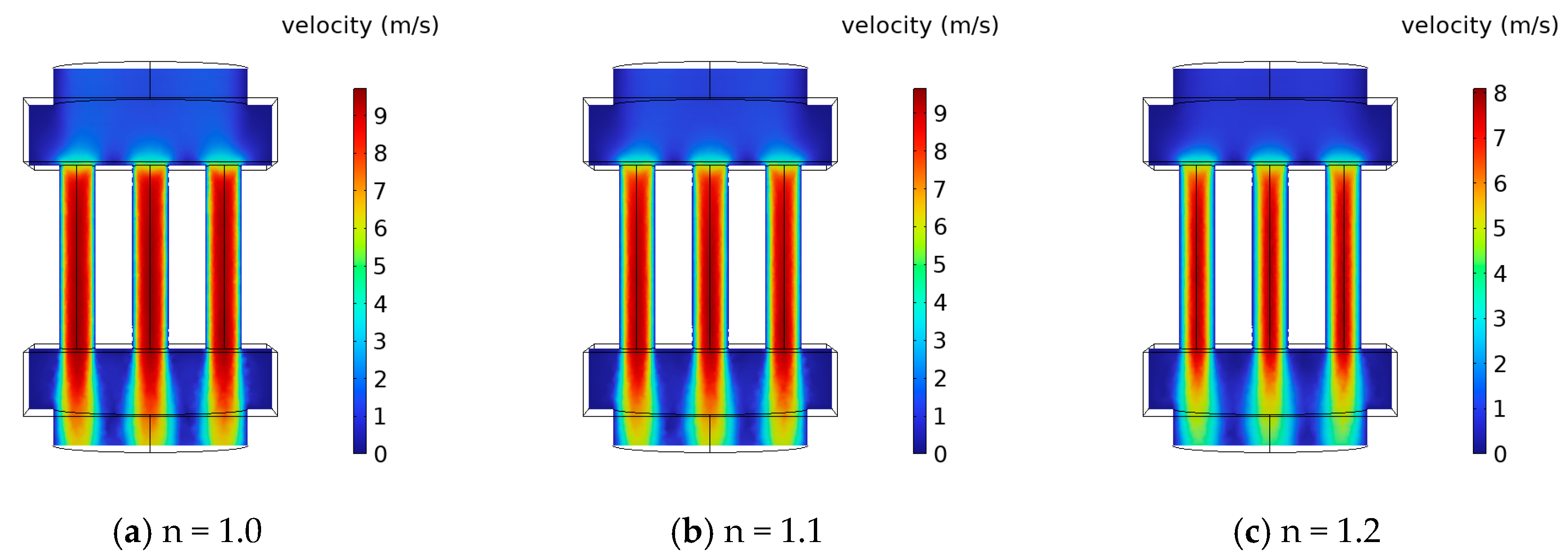
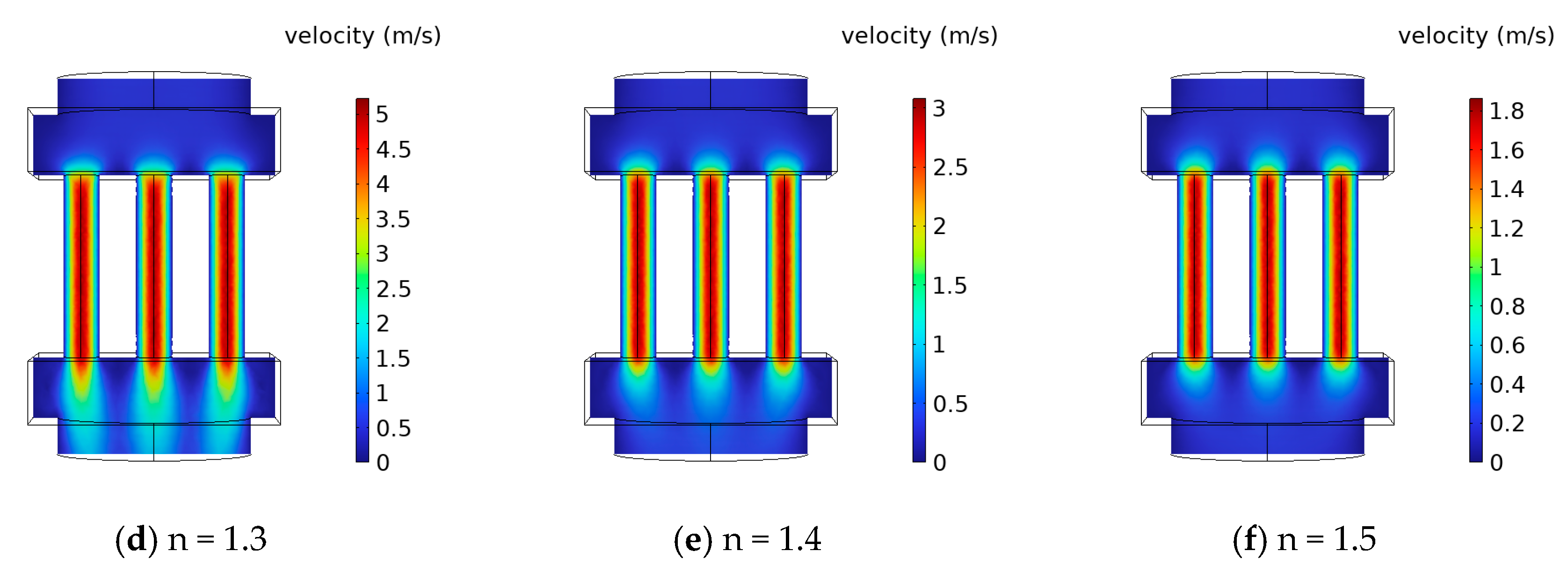
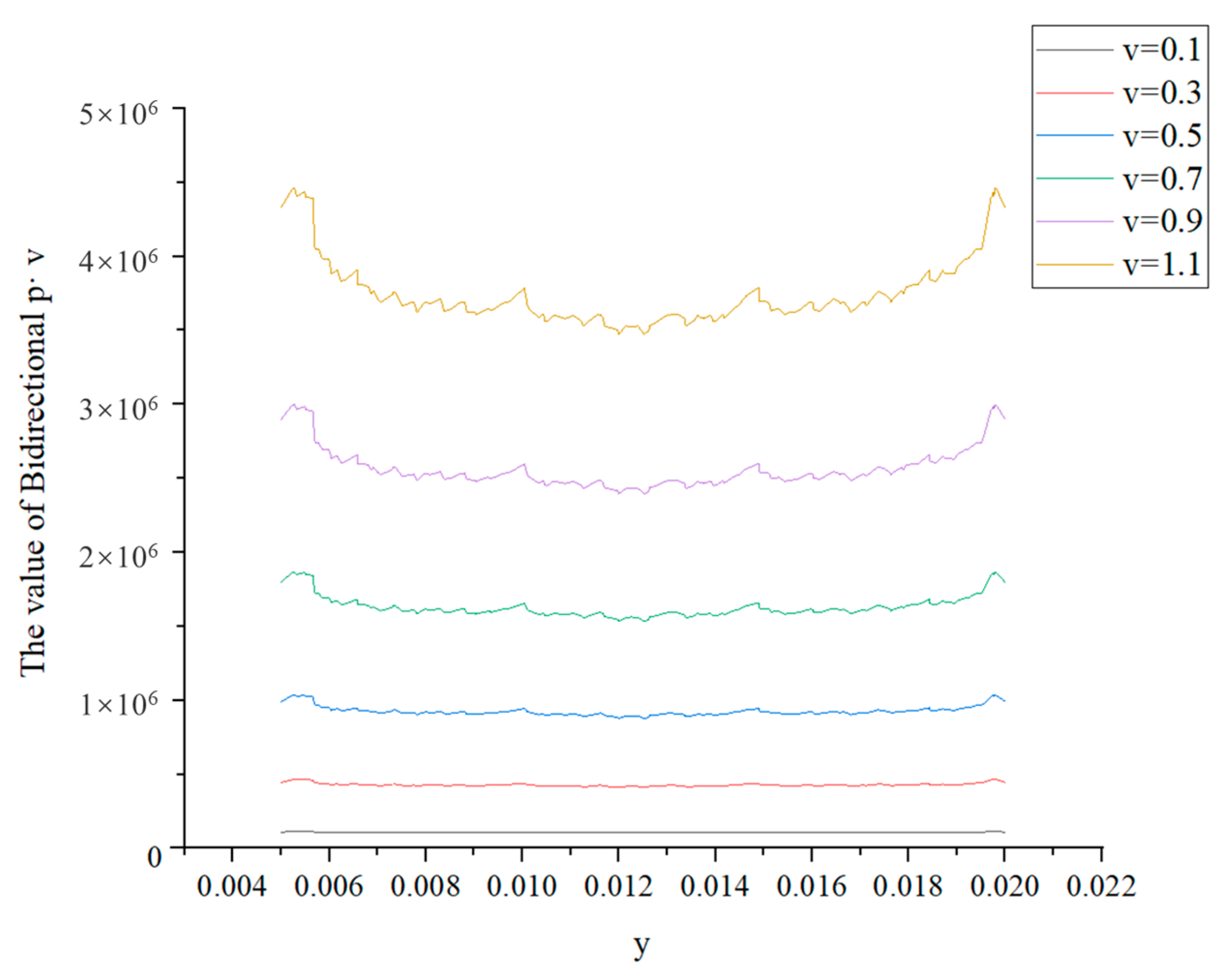
4.2.2. Effect of Flow Velocity on the Polishing Process

To investigate the impact of different flow velocities within the flow channel on the polishing effectiveness, a simulation study was conducted with a fixed flow behavior index of 1.3, utilizing the inlet velocity (referred to as “boundary condition of inlet 3”) as the inlet boundary condition for the initial mixture. By varying the inlet velocity (v), the flow velocity (U) within the processing area of the flow channel was modified, thereby obtaining the pressure field distribution and velocity field distribution for different flow velocities under the same flow behavior index. The results are presented in Figure 11 and Figure 12. The figures demonstrate that as the inlet flow velocity increases, the pressure exerted by the polishing fluid on the inner wall surface intensifies, accompanied by a linear rise in the flow velocity within the flow channel. Figure 12 reveals that at lower flow velocities, the polishing fluid exhibits the premature formation of a fully developed laminar flow within the processing area. This premature formation of laminar flow facilitates the formation of an adhesive slurry layer on the inner wall surface. Consequently, the micro-particles and slurry generated during cutting become challenging to remove with the limited fluid flow at lower velocities. Additionally, direct contact between the new fluid and the inner wall surface is hindered, impeding subsequent polishing operations. As the flow velocity increases, the fluid exhibits improved fluidity, and the inlet region of the fully developed laminar flow extends further. Under the influence of higher flow velocities, the viscous slurry and attached cutting waste are more effectively removed by the fluid flow. This enhanced fluid flow capability enhances the polishing effect on the inner wall surface, particularly during continuous reciprocating polishing operations.
Similarly, for the purpose of facilitating the computation and characterization of the flow field, the inner surface of the outer boundary within the simulated processing area was extracted. This entails the multiplication of the pressure line matrix and the velocity line matrix within any given bus, resulting in a relative representation of the material removal rate at different locations, as depicted in Figure 13. Examination of the figure reveals an overall increase in the value of p·v as the inlet flow velocity rises. This indicates that increasing the inlet flow velocity improves the material removal rate, with a more pronounced effect at higher velocities. Concurrently, as the inlet flow velocity increases, the fluctuations in the value of p·v also intensify, leading to a greater impact on the uniformity of the inner wall surface roughness, particularly within the narrow inlet section. Consequently, to enhance the overall polishing efficacy of the inner wall surface, the inlet velocity should not be excessively high. In cases where a higher inlet velocity is utilized, the implementation of an appropriately increased drainage section yields a more pronounced improvement in polishing uniformity.

5. Conclusions

This study builds upon previous research on leveraging the shear thickening rheological properties of polishing fluids containing shear thickening agents. The aim was to enhance the adhesive force between abrasive particles, thereby creating a “flexible fixed abrasive tool”. The primary objective was to achieve the efficient processing of small titanium alloy hole workpieces found in medical devices. Consequently, this paper introduces a novel shear thickening polishing method specifically designed for the inner wall of such workpieces.
(1) The present study establishes an abrasive flow dynamics model and material removal model for the inner wall of small titanium alloy hole workpieces in shear thickening abrasive flow machining medical devices, based on the Preston equation and fluid dynamics theory. The material removal rate (MMR) is influenced by the flow velocity (U) of the polishing fluid and the flow behavior index (n), as inferred from the material removal model. When U is held constant, the shear thickening abrasive flow polishing fluid (n > 1) exhibits superior processing effects compared to the Newtonian fluid (n = 1). Moreover, increasing the value of n enhances the shear thickening effect, leading to a further increase in the material removal rate. Conversely, with a constant flow behavior index, the material removal rate rises with increasing U, indicating that higher flow velocities are beneficial for improving processing efficiency.
(2) Through the simulation, pressure distributions on the inner wall surface of the fluid pair within the flow channel, velocity variations within the flow field, and alterations in the value of p·v affecting the material removal rate were obtained for different flow behavior indices (n). The results demonstrate that increasing the flow behavior index (n) enhances the fluid’s pressure on the inner wall surface and augments the material removal rate. However, it also decreases the fluidity of the abrasive flow due to heightened viscosity. Excessive flow behavior indices result in early formation of a viscous boundary layer on the inner wall, impeding waste removal and reducing contact between the fluid and inner wall surface. As a consequence, the material removal rate becomes uneven, leading to reduced polishing efficiency. Thus, for actual machining processes involving small titanium alloy hole workpieces with an inner diameter of 3 mm, wall thickness of 1 mm, and length of 15 mm, it is preferable to select a fluid with a flow behavior index ranging from 1.3 to 1.4.
(3) Numerical simulations were conducted to examine the pressure distribution on the inner wall surface of the fluid pair within the flow channel, variations in velocity within the flow field, and changes in the value of p·v affecting the material removal rate under different flow velocities. The findings indicate that increasing the flow velocity of the fluid in the processing area enhances the fluid’s pressure on the inner wall surface, resulting in a higher material removal rate. Additionally, under constant viscosity, higher flow velocities contribute to improved fluidity. However, excessively high flow velocities often exacerbate the instability of the abrasive flow, leading to significant fluctuations in the material removal rate. Notably, the material removal rate exhibits particularly pronounced fluctuations at the fluid inlet and outlet, hampering consistent polishing effects on the inner wall surface. Consequently, for the practical processing of small titanium alloy hole workpieces with an inner diameter of 3 mm, wall thickness of 1 mm, and length of 15 mm, it is advisable to set the inlet flow velocity at a moderate level, preferably between 0.5 m/s and 0.7 m/s.

Author Contributions

Conceptualization, R.J.; data curation, W.M.; formal analysis, B.Y. and W.M.; funding acquisition, L.Z.; investigation, B.Y.; methodology, B.Y.; project administration, X.Z.; software, R.J.; supervision, X.Z.; writing—original draft, R.J.; writing—review and editing, L.Z. All authors have read and agreed to the published version of the manuscript.

Funding

This research was funded by the National Natural Science Foundation of China (51875526, 52075493, U21A20122) and the Zhejiang Provincial Natural Science Foundation of China (LGG19E050025).

Institutional Review Board Statement

Not applicable.

Informed Consent Statement

Not applicable.

Data Availability Statement

The data presented in this study are available on request from the corresponding author.

Conflicts of Interest

The authors declare that the research was conducted in the absence of any commercial or financial relationship that could be construed as a potential conflict of interest.

References

  1. Wang, X.; Zhang, B.; Qiao, Y.; Sun, F. Chemo-mechanical abrasive flow machining (CM-AFM): A novel high-efficient technique for polishing diamond thin coatings on inner hole surfaces. J. Manuf. Process. 2021, 69, 152–164. [Google Scholar] [CrossRef]
  2. Zhang, L.; Yuan, Z.; Qi, Z.; Cai, D.; Cheng, Z.; Qi, H. CFD-based study of the abrasive flow characteristics within constrained flow passage in polishing of complex titanium alloy surfaces. Powder Technol. 2018, 333, 209–218. [Google Scholar] [CrossRef]
  3. Ji, R.; Qi, Z.; Chen, J.; Zhang, L.; Lin, K.; Lu, S.; Li, Y. Numerical and Experimental Investigation on the Abrasive Flow Machining of Artificial Knee Joint Surface. Crystals 2023, 13, 430. [Google Scholar] [CrossRef]
  4. Peng, Z.; Zhang, X.; Liu, L.; Xu, G.; Wang, G.; Zhao, M. Effect of high-speed ultrasonic vibration cutting on the microstructure, surface integrity, and wear behavior of titanium alloy. J. Mater. Res. Technol. 2023, 24, 3870–3888. [Google Scholar] [CrossRef]
  5. Ming, W.; Guo, X.; Xu, Y.; Zhang, G.; Jiang, Z.; Li, Y.; Li, X. Progress in non-traditional machining of amorphous alloys. Ceram. Int. 2023, 49, 1585–1604. [Google Scholar] [CrossRef]
  6. Zhao, J.; Jiang, E.; Qi, H.; Ji, S.; Chen, Z. A novel polishing method for single-crystal silicon using the cavitation rotary abrasive flow. Precis. Eng. 2020, 61, 72–81. [Google Scholar] [CrossRef]
  7. Hu, W.; Teng, Q.; Hong, T.; Saetang, V.; Qi, H. Stress field modeling of single-abrasive scratching of BK7 glass for surface integrity evaluation. Ceram. Int. 2022, 48, 12819–12828. [Google Scholar] [CrossRef]
  8. Qian, H.; Chen, M.; Qi, Z.; Teng, Q.; Qi, H.; Zhang, L.; Shan, X. Review on Research and Development of Abrasive Scratching of Hard Brittle Materials and Its Underlying Mechanisms. Crystals 2023, 13, 428. [Google Scholar] [CrossRef]
  9. Qi, H.; Wen, D.; Lu, C.; Li, G. Numerical and experimental study on ultrasonic vibration-assisted micro-channelling of glasses using an abrasive slurry jet. Int. J. Mech. Sci. 2016, 110, 94–107. [Google Scholar] [CrossRef]
  10. Qi, H.; Wen, D.; Yuan, Q.; Zhang, L.; Chen, Z. Numerical investigation on particle impact erosion in ultrasonic-assisted abrasive slurry jet micro-machining of glasses. Powder Technol. 2017, 314, 627–634. [Google Scholar] [CrossRef]
  11. Qi, H.; Qin, S.; Cheng, Z.; Teng, Q.; Hong, T.; Xie, Y. Towards understanding performance enhancing mechanism of micro-holes on K9 glasses using ultrasonic vibration-assisted abrasive slurry jet. J. Manuf. Process. 2021, 64, 585–593. [Google Scholar] [CrossRef]
  12. Qi, H.; Qin, S.; Cheng, Z.; Zou, Y.; Cai, D.; Wen, D. DEM and experimental study on the ultrasonic vibration-assisted abrasive finishing of WC-8Co cemented carbide cutting edge. Powder Technol. 2021, 378, 716–723. [Google Scholar] [CrossRef]
  13. Jain, V.K.; Adsul, S.G. Experimental investigations into abrasive flow machining (AFM). Int. J. Mach. Tools Manuf. 2000, 40, 1003–1021. [Google Scholar] [CrossRef]
  14. Ge, J.; Li, C.; Gao, Z.; Ren, Y.; Xu, X.; Li, C.; Xie, Y. Softness abrasive flow polishing method using constrained boundary vibration. Powder Technol. 2021, 382, 173–187. [Google Scholar] [CrossRef]
  15. Li, M.; Lyu, B.; Yuan, J.; Dong, C.; Dai, W. Shear-thickening polishing method. Int. J. Mach. Tools Manuf. 2015, 94, 88–99. [Google Scholar] [CrossRef]
  16. Li, M.; Lyu, B.; Yuan, J.; Yao, W.; Zhou, F.; Zhong, M. Evolution and equivalent control law of surface roughness in shear-thickening polishing. Int. J. Mach. Tools Manuf. 2016, 108, 113–126. [Google Scholar] [CrossRef]
  17. Lyu, B.H.; Shao, Q.; Hang, W.; Chen, S.H.; He, Q.K.; Yuan, J.L. Shear Thickening Polishing of Black Lithium Tantalite Substrate. Int. J. Precis. Eng. Manuf. 2020, 21, 1663–1675. [Google Scholar] [CrossRef]
  18. Hoyt, J.W. Some applications of non-newtonian fluid flow. In Rheology Series; Siginer, D.A., De Kee, D., Chhabra, R.P., Eds.; Elsevier: Amsterdam, The Netherlands, 1999; Volume 8, pp. 797–826. [Google Scholar]
  19. Li, M.; Liu, M.; Riemer, O.; Karpuschewski, B.; Tang, C. Origin of material removal mechanism in shear thickening-chemical polishing. Int. J. Mach. Tools Manuf. 2021, 170, 103800. [Google Scholar] [CrossRef]
  20. Yuan, H.Y.; Yang, W.B.; Zhang, L.; Hong, T. Model development of stress intensity factor on 7057T6 aluminum alloy using extended finite element method. Coatings 2023, 13, 581. [Google Scholar] [CrossRef]
  21. Wang, Y.Y.; Wang, Z.; Ni, P.C.; Wang, D.J.; Guo, S.H.; Chen, Z.Z. Experimental and numerical study on regulation of cutting temperature during the circular sawing of 45 steel. Coatings 2023, 13, 758. [Google Scholar] [CrossRef]
Figure 1. Shear thickening abrasive flow polishing principle.
Coatings 13 01492 g001
Figure 2. Pressure curves at different flow behavior indices, n.
Coatings 13 01492 g002
Figure 3. Curve of material removal rate at different flow velocities, U.
Coatings 13 01492 g003
Figure 4. Model construction.
Coatings 13 01492 g004
Figure 5. Model grid division.
Coatings 13 01492 g005
Figure 6. Surface pressure distribution of processing area with different flow behavior indices.
Coatings 13 01492 g006
Figure 7. Velocity distribution of different flow behavior indices under the same inlet velocity.
Coatings 13 01492 g007
Figure 8. Unidirectional p·v line matrix of different flow behavior indices at the same inlet velocity.
Coatings 13 01492 g008
Figure 9. Bidirectional p·v line matrix of different flow behavior indices at the same inlet velocity.
Coatings 13 01492 g009
Figure 10. Velocity distribution of different flow behavior indices under the same inlet pressure.
Coatings 13 01492 g010aCoatings 13 01492 g010b
Figure 11. Surface pressure distribution of machining area with different flow velocities under the same flow behavior index.
Coatings 13 01492 g011
Figure 12. Velocity distribution of different flow velocities under the same flow behavior index.
Coatings 13 01492 g012
Figure 13. Bidirectional p·v line matrix of different flow velocities at the same flow behavior index.
Coatings 13 01492 g013
Table 1. Simulation parameters.
Simulation ParametersValues
Material of hole inner wallTi-6Al-4V
Fluid density/(kg · m−3)1500
Fluid dynamic viscosity/(Pa · s) 0.05 γ ˙ n 1
Flow behavior index n1.0, 1.1, 1.2, 1.3, 1.4, 1.5
Density of abrasive particles/(kg · m−3)3170
Size of abrasive particles/(μm)10
Volume fraction of abrasive particles (%)10
Boundary condition of inlet 1
Boundary condition of inlet 2
Boundary condition of inlet 3
Speed control, normal flow is 0.5 m/s
Pressure control, pressure is 0.1 MPa
Velocity control, normal flow 0. 1–1.1 m/s
(interval is 0.2 m/s)
Boundary condition of OutletPressure control (p = 0), Inhibition of reflux
Disclaimer/Publisher’s Note: The statements, opinions and data contained in all publications are solely those of the individual author(s) and contributor(s) and not of MDPI and/or the editor(s). MDPI and/or the editor(s) disclaim responsibility for any injury to people or property resulting from any ideas, methods, instructions or products referred to in the content.

