
Structure and High-Temperature Oxidation Performance of Si-Co Diffusion Coatings Prepared on a TiAl-Nb Alloy
Abstract
:1. Introduction
2. Materials and Methods
3. Results
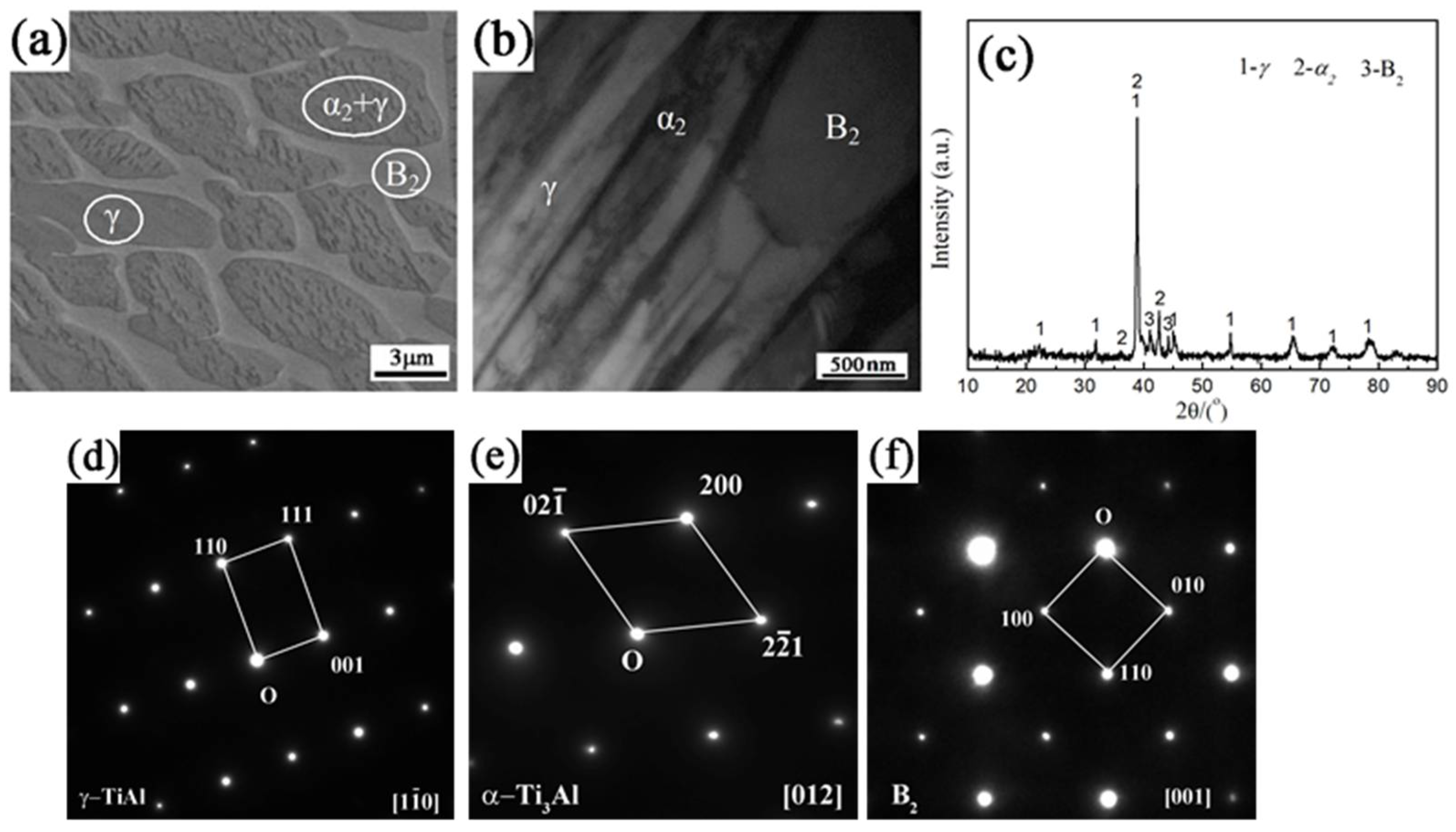
3.1. Coating Structures
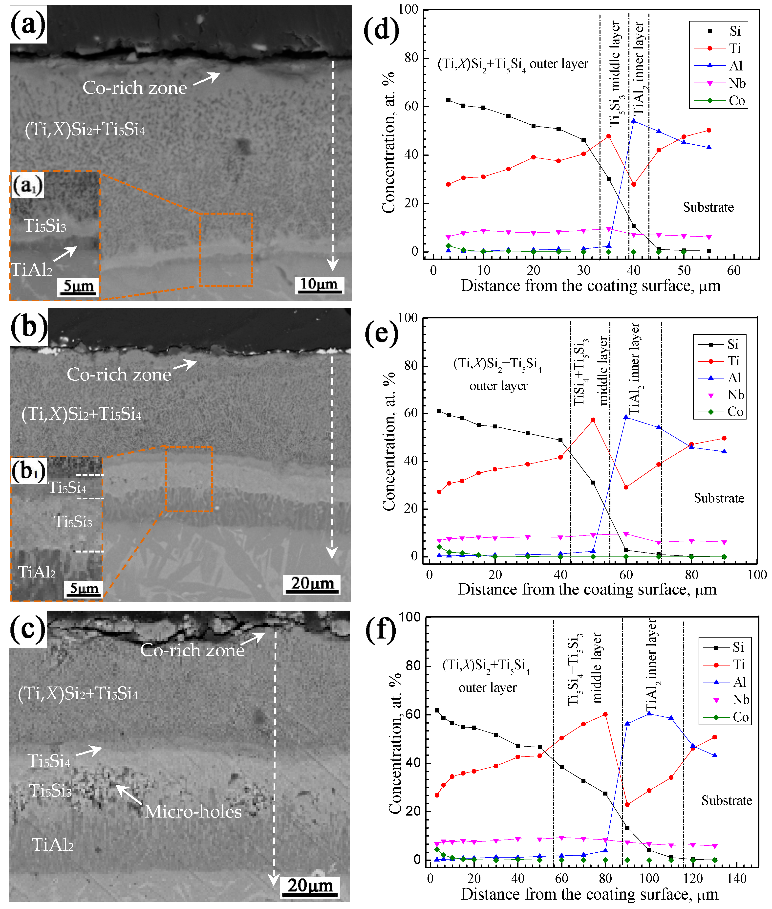
3.1.1. Effects of Co-Deposition Temperatures
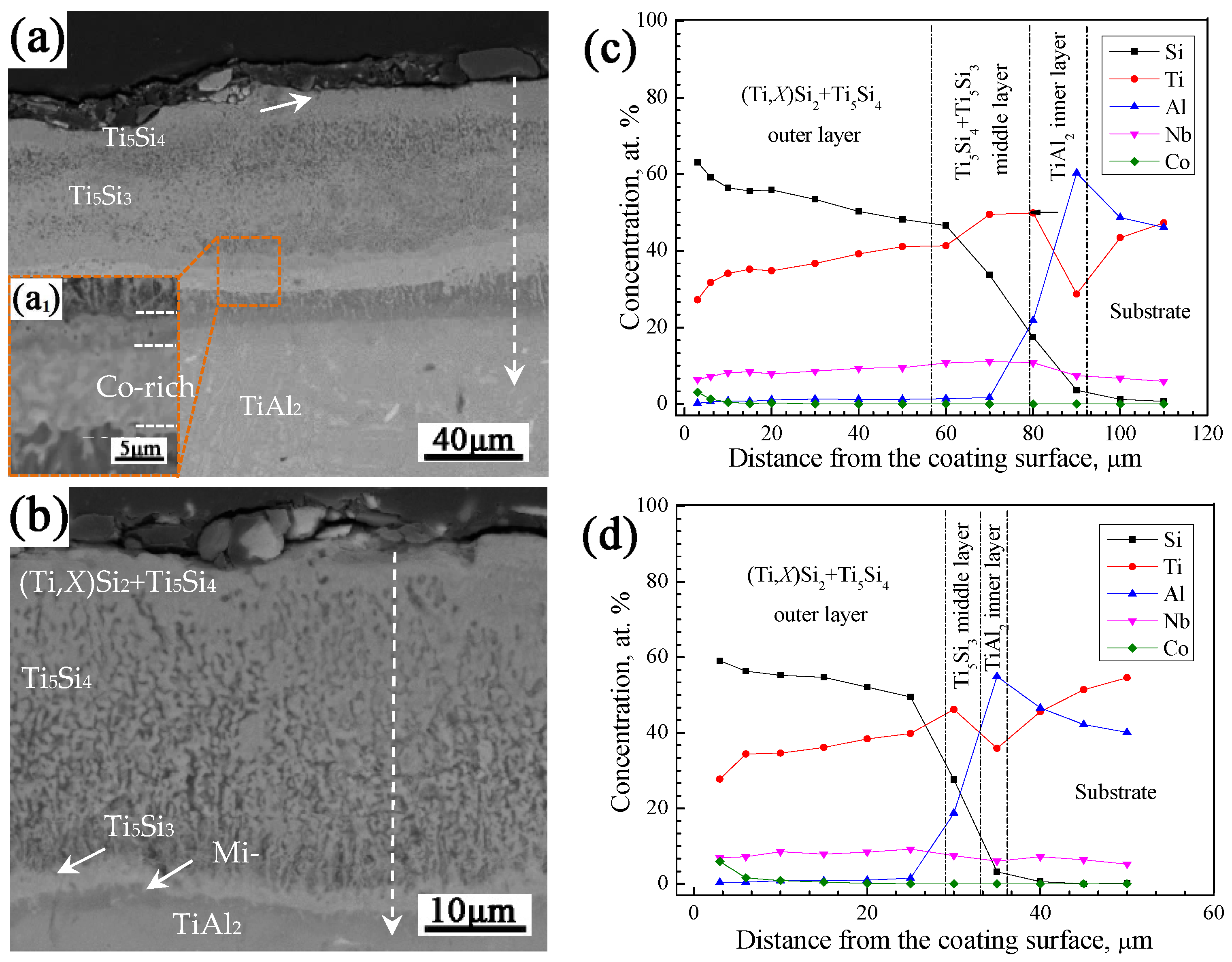
3.1.2. Effects of Pack Co Contents
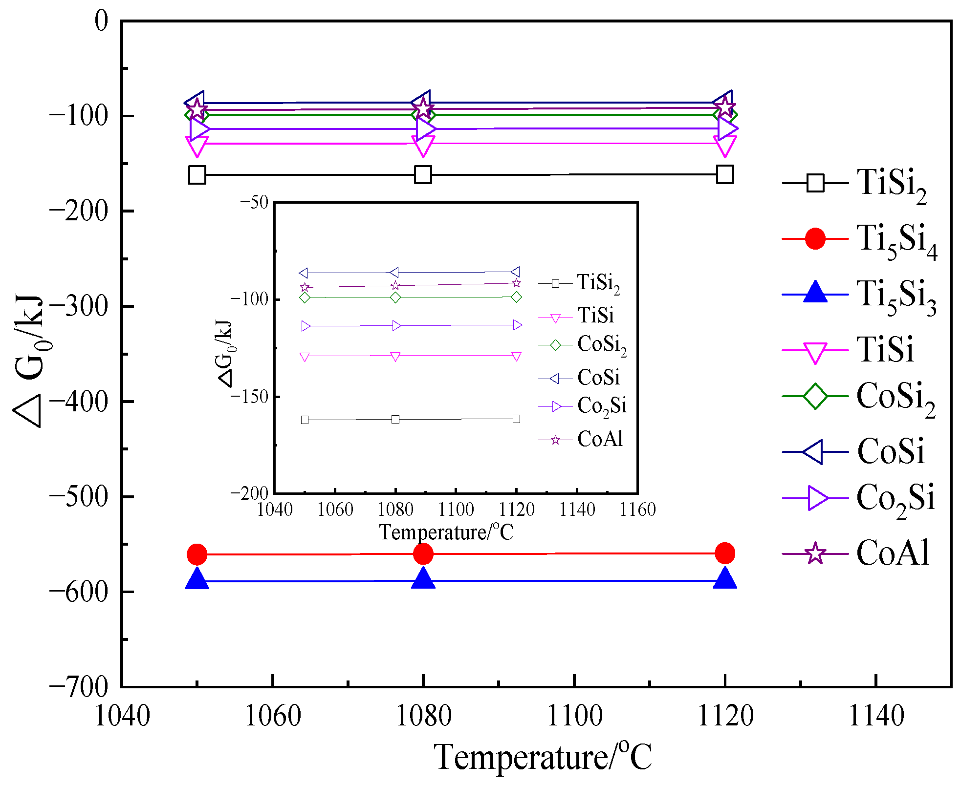
3.2. Coating Formation Process
3.3. Isothermal Oxidation Performance
3.3.1. Oxidation Kinetics
3.3.2. Scale Morphologies
3.3.3. Discussion
4. Conclusions
Author Contributions
Funding
Institutional Review Board Statement
Informed Consent Statement
Data Availability Statement
Conflicts of Interest
References
- Duan, B.H.; Yang, Y.C.; He, S.Y.; Feng, Q.S.; Mao, L.; Zhang, X.X.; Jiao, L.N.; Lu, X.G.; Chen, G.Y.; Li, C.H. History and development of γ-TiAl alloys and the effect of alloying elements on their phase transformations. J. Alloys Compd. 2022, 909, 164811. [Google Scholar] [CrossRef]
- Kim, S.W.; Hong, J.K.; Na, Y.S.; Yeom, J.T.; Kim, S.E. Development of TiAl alloys with excellent mechanical properties and oxidation resistance. Mater. Des. 2014, 54, 814–819. [Google Scholar] [CrossRef]
- Banumathy, S.; Neelam, N.S.; Chandravanshi, V.; Bhattacharjee, A.; Ravi, K.R. The Effect of Nb addition on microstructure, oxidation behavior and strength of some γ-TiAl alloys. Mater. Today Proc. 2018, 5, 5514–5520. [Google Scholar] [CrossRef]
- Lin, J.P.; Zhao, L.L.; Li, G.Y.; Zhang, L.Q.; Song, X.P.; Ye, F.; Chen, G.L. Effect of Nb on oxidation behavior of high Nb containing TiAl alloys. Intermetallics 2011, 19, 131–136. [Google Scholar] [CrossRef]
- Pflumm, R.; Friedle, S.; Schütze, M. Oxidation protection of γ-TiAl-based alloys–a review. Intermetallics 2015, 56, 1–14. [Google Scholar] [CrossRef]
- Zhou, C.G.; Xu, H.B.; Gong, S.K.; Kim, Y. A study of aluminide coatings on TiAl alloys by the pack cementation method. Mater. Sci. Eng. A 2003, 341, 169–173. [Google Scholar] [CrossRef]
- Sasaki, T.; Yagi, T.; Watanabe, T.; Yanagisawa, A. Aluminizing of TiAl-based alloy using thermal spray coating. Surf. Coat. Technol. 2011, 205, 3900–3904. [Google Scholar] [CrossRef]
- Dudziak, T.; Du, H.L.; Datta, P.K.; Wilson, A.; Ross, I.M.; Moser, M.; Braun, R. Sulphidation/oxidation behaviour of TiAlCr and Al2Au coated Ti45Al8Nb alloy at 750 °C. Corros. Sci. 2009, 51, 1189–1196. [Google Scholar] [CrossRef]
- Braun, R.; Kelm, K.; Fröhlich, M.; Leyens, C. Oxidation resistance of γ-TiAl based alloy Ti–45Al–8Nb coated with intermetallic Ti–Al–Cr–Y layers and EB-PVD zirconia topcoats at 950 °C in air. Surf. Coat. Technol. 2013, 222, 128–134. [Google Scholar] [CrossRef]
- Han, D.; Liu, D.; Niu, Y.; Qi, Z.; Pan, Y.; Xu, H.; Zheng, X.; Chen, G. Interface stability of NiCrAlY coating without and with a Cr or Mo diffusion barrier on Ti-42Al-5Mn alloy. Corros. Sci. 2021, 188, 109538. [Google Scholar] [CrossRef]
- Dudziak, T.; Datta, P.K.; Mayrhofer, P.H.; Rovere, F. High Temperature Oxidation Resistance of CrAlYN-Coated Ti45Al8Nb. Oxid. Met. 2011, 75, 359–376. [Google Scholar] [CrossRef]
- Wang, S.Q.; Xie, F.Q.; Wu, X.Q.; Chen, L.Y. CeO2 doped Al2O3 composite ceramic coatings fabricated on γ–TiAl alloys via cathodic plasma electrolytic deposition. J. Alloys Compd. 2019, 788, 632–638. [Google Scholar] [CrossRef]
- Wu, L.K.; Xia, J.J.; Cao, H.Z.; Liu, W.J.; Hou, G.Y.; Tang, Y.P.; Zheng, G.Q. Improving the high-temperature oxidation resistance of TiAl alloy by anodizing in Methanol/NaF solution. Oxid. Met. 2018, 90, 617–631. [Google Scholar] [CrossRef]
- Yao, J.; He, Y.; Wang, D.; Lin, J. High-temperature oxidation resistance of (Al2O3–Y2O3)/(Y2O3-stabilized ZrO2) laminated coating on 8Nb–TiAl alloy prepared by a novel spray pyrolysis. Corros. Sci. 2014, 80, 19–27. [Google Scholar] [CrossRef]
- Ma, X.; He, Y.; Lin, J.; Wang, D.; Zhang, J. Effect of a magnetron sputtered (Al2O3–Y2O3)/(Pt–Au) laminated coating on hot corrosion resistance of 8Nb–TiAl alloy. Surf. Coat. Technol. 2012, 206, 2690–2697. [Google Scholar] [CrossRef]
- Cockeram, B.V.; Rapp, R.A. The kinetics of multilayered titanium-silicide coatings grown by the pack cementation method. Metall. Mater. Trans. A 1995, 26, 777–791. [Google Scholar] [CrossRef]
- Huang, J.; Zhao, F.; Cui, X.; Wang, J.; Xiong, T. Long-term oxidation behavior of silicon-aluminizing coating with an in-situ formed Ti5Si3 diffusion barrier on γ-TiAl alloy. Appl. Surf. Sci. 2022, 582, 152444. [Google Scholar]
- Mitra, R. Mechanical behaviour and oxidation resistance of structural silicides. Int. Mater. Rev. 2006, 51, 13–64. [Google Scholar] [CrossRef]
- Xiao, L.; Zhou, X.; Wang, Y.; Pu, R.; Zhao, G.; Shen, Z.; Zhao, X. Formation and oxidation behavior of Ce-modified MoSi2-NbSi2 coating on niobium alloy. Corros. Sci. 2020, 173, 108751. [Google Scholar] [CrossRef]
- Li, H.J.; Feng, T.; Fu, Q.G.; Wu, H.; Shen, X.T. Oxidation and erosion resistance of MoSi2–CrSi2–Si/SiC coated C/C composites in static and aerodynamic oxidation environment. Carbon 2010, 48, 1636–1642. [Google Scholar] [CrossRef]
- Zhu, X.; Zhang, Y.; Qiang, X.; Zhang, J.; Su, Y.; Li, T. An oxidation protective coating prepared by SiC densifying HfB2-SiC skeleton for SiC-coated C/C composites at 1473, 1773, and 1973 K. Corros. Sci. 2022, 207, 110559. [Google Scholar] [CrossRef]
- Liu, Y.; Hu, R.; Yang, J.; Li, J. Tensile properties and fracture behavior of in-situ synthesized Ti2AlN/Ti48Al2Cr2Nb composites at room and elevated temperatures. Mat. Sci. Eng. A 2017, 679, 7–13. [Google Scholar] [CrossRef]
- Zhang, L.; Wu, J. Thermal expansion and elastic moduli of the silicide based intermetallic alloys Ti5Si3 (X) and Nb5Si3. Scr. Mater. 1997, 38, 307–313. [Google Scholar] [CrossRef]
- Xiang, Z.D.; Rose, S.R.; Datta, P.K. Codeposition of Al and Si to form oxidation-resistant coatings on γ-TiAl by the pack cementation process. Mater. Chem. Phys. 2003, 80, 482–489. [Google Scholar] [CrossRef]
- Yu, W.H.; Tian, J.; Tian, W.; Zhao, J.; Li, Y.; Liu, Y. Study of yttrium and cerium on the oxidation resistance of silicide coatings prepared on Ti-6Al-4V alloy by pack-cementation process. J. Rare Earth 2015, 33, 221–226. [Google Scholar] [CrossRef]
- Koo, C.H.; Yu, T.H. Pack cementation coatings on Ti3Al–Nb alloys to modify the high-temperature oxidation properties. Surf. Coat. Technol. 2000, 126, 171–180. [Google Scholar] [CrossRef]
- Semenov, N.A. Oxidation resistance of niobium coated with titanium disilicide. Powder Metall. Met. Ceram. 2000, 39, 560–562. [Google Scholar] [CrossRef]
- Bai, C.Y.; Luo, Y.J.; Koo, C.H. Improvement of high temperature oxidation and corrosion resistance of superalloy IN-738LC by pack cementation. Surf. Coat. Technol. 2004, 183, 74–88. [Google Scholar] [CrossRef]
- Strydom, W.J.; Lombaard, J.C.; Pretorius, R. Thermal oxidation of the silicides CoSi2, CrSi2, NiSi2, PtSi, TiSi2 and ZrSi2. Thin Solid Films 1985, 131, 215–231. [Google Scholar] [CrossRef]
- Becker, S.; Rahmel, A.; Schütze, M. Oxidation of TiSi2 and MoSi2. Solid State Ionics 1992, 53, 280–289. [Google Scholar] [CrossRef]
- Qiao, M.; Zhou, C.G. Co-deposition of Co–Al–Y on nickel base superalloys by pack cementation process. Corros. Sci. 2013, 75, 454–460. [Google Scholar]
- Zamoum, F.; Benlaharche, T.; David, N.; Podor, R.; Vilasi, M. Kinetics of high temperature oxidation of (Nb,Co,Cr)7Si6 and (Nb,Co,Cr)8Si7 silicide compounds. Intermetallics 2008, 16, 498–507. [Google Scholar] [CrossRef]
- Thanneeru, R.; Patil, S.; Deshpande, S.; Seal, S. Effect of trivalent rare earth dopants in nanocrystalline ceria coatings for high-temperature oxidation resistance. Acta Mater. 2007, 55, 3457–3466. [Google Scholar]
- Zhao, L.L.; Li, G.Y.; Zhang, L.Q.; Lin, J.P.; Song, X.P.; Ye, F.; Chen, G.L. Influence of Y addition on the long time oxidation behaviors of high Nb containing TiAl alloys at 900 °C. Intermetallics 2010, 18, 1586–1596. [Google Scholar] [CrossRef]
- Qu, S.J.; Tang, S.Q.; Feng, A.H.; Feng, C.; Shen, J.; Chen, D.L. Microstructural evolution and high-temperature oxidation mechanisms of a titanium aluminide based alloy. Acta Mater. 2018, 148, 300–310. [Google Scholar] [CrossRef]
- Bianco, R.; Rapp, R.A.; Jacobson, N.S. Volatile species in halide-activated diffusion coating packs. Oxid. Met. 1992, 38, 33–43. [Google Scholar]
- Tian, J.; Zhang, C.; Li, X.; Lai, S.; Xie, W.L.; Tian, W. Wear Behavior of Silicon-Cobalt Composite Coating Deposited on TiAl Alloy by Pack Cementation Process. J. Mater. Eng. Perform. 2022, 31, 4811–4819. [Google Scholar] [CrossRef]
- Xiang, L.L.; Zhao, L.L.; Wang, Y.L.; Zhang, L.Q.; Lin, J.P. Synergistic effect of Y and Nb on the high temperature oxidation resistance of high Nb containing TiAl alloys. Intermetallics 2012, 27, 6–13. [Google Scholar]
- Yamane, T.; Fujiishi, Y.; Araki, H.; Minamino, Y.; Saji, S.; Takahashi, J.; Miyamoto, Y. Phase diagrams of the Ti-Si system under high pressure. J. Mater. Sci. Lett. 1994, 13, 200–202. [Google Scholar]
- Falke, M.; Gebhardt, B.; Beddies, G.; Teichert, S.; Hinneberg, H.J. Epitaxial CoSi2 by solid phase reaction of Co/Ti and Co/Hf bilayers on Si(001). Microelectron. Eng. 2001, 55, 171–175. [Google Scholar]
- Chen, G.L.; Wang, X.T.; Ni, K.Q.; Hao, S.M.; Cao, J.X.; Ding, J.J.; Zhang, X. Investigation on the 1000, 1150 and 1400 °C isothermal section of the TiAlNb system. Intermetallics 1996, 4, 13–22. [Google Scholar] [CrossRef]
- Pang, X.Z.; Chen, X.; Yang, J.; Pang, M.; Yang, W.; Zhan, Y. Influence of Nb concentration on the structure, stability, and electronic and mechanical properties of D022 Al3Ti by first-principles calculations and experiments. J. Phys. Chem. Solids 2019, 131, 243–253. [Google Scholar] [CrossRef]
- Kahrobaee, Z.; Palm, M. Experimental investigation of Ti–Al–Si phase equilibria at 800–1200 °C. J. Alloys Compd. 2022, 924, 166223. [Google Scholar]
- Kung, S.C.; Rapp, R.A. Analyses of the gaseous species in halide-activated cementation coating packs. Oxid. Met. 1989, 32, 89–109. [Google Scholar]
- Xiang, Z.D.; Datta, P.K. Relationship between pack chemistry and aluminide coating formation for low-temperature aluminisation of alloy steels. Acta Mater. 2006, 54, 4453–4463. [Google Scholar]
- Krendelsberger, N.; Weitzer, F.; Schuster, J.C.; Stein, F. Constitution of the ternary system Co–Si–Ti. Intermetallics 2013, 38, 92–101. [Google Scholar] [CrossRef]
- Sahu, B.P.; Ray, M.; Mitra, R. Structure and properties of Ni1-xTixN thin films processed by reactive magnetron co-sputtering. Mater. Charact. 2020, 169, 110604. [Google Scholar]


| Species | ΔfG/(kJ/mol) | Partial Pressures/MPa | ||||
|---|---|---|---|---|---|---|
| 1050 °C | 1080 °C | 1120 °C | 1050 °C | 1080 °C | 1120 °C | |
| SiF | −308.9 | −314.8 | −322.4 | 4.6 × 10⁻¹¹ | 1.1 × 10⁻¹⁰ | 8.9 × 10⁻⁹ |
| SiF2 | −627.8 | −628.5 | −629.5 | 5.4 × 10⁻⁶ | 7.6 × 10⁻⁵ | 1.3 × 10⁻⁵ |
| SiF3 | −684.8 | −683.9 | −682.6 | 4.3 × 10⁻⁹ | 5.2 × 10⁻⁸ | 6.5 × 10⁻⁷ |
| SiF4 | −713.0 | −710.8 | −707.9 | 9.3 × 10⁻⁵ | 1.8 × 10⁻⁵ | 4.4 × 10⁻⁴ |
| CoF | −146.8 | −152.0 | −160.0 | 8.2 × 10⁻¹⁰ | 2.3 × 10⁻⁹ | 3.6 × 10⁻⁸ |
| CoF2 | −411.7 | −412.8 | −414.1 | 9.4 × 10⁻⁷ | 1.4 × 10⁻⁷ | 4.3 × 10⁻⁶ |
| CoF3 | −344.3 | −345.1 | −345.7 | 5.5 × 10⁻⁸ | 7.9 × 10⁻⁷ | 2.1 × 10⁻⁷ |
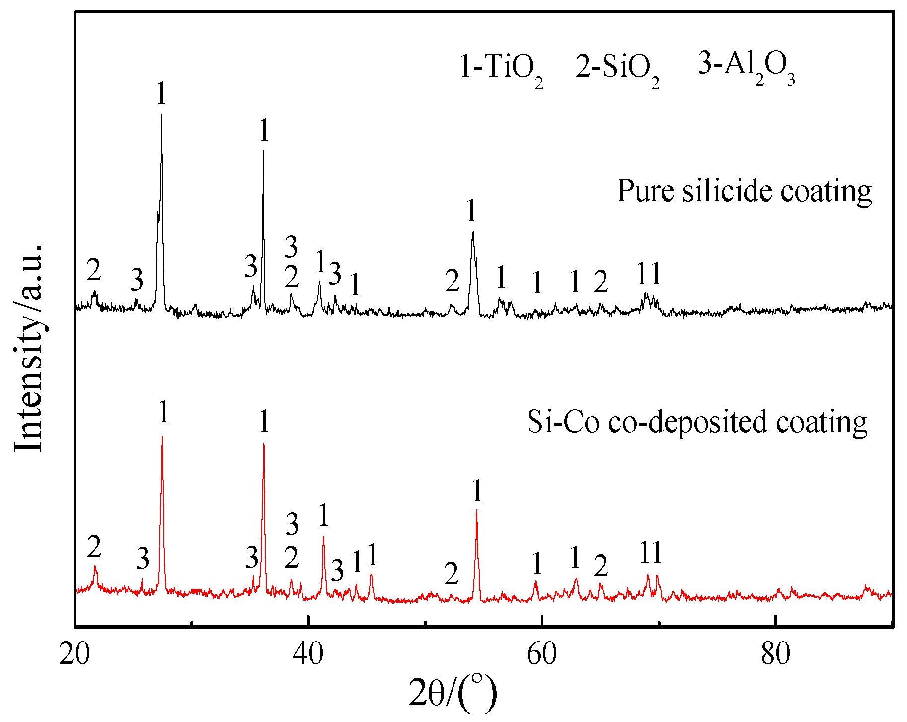
| Specimens | Fitted Linear Equation | kp (mg2cm−4h−1) | Correlation Coefficient/R |
|---|---|---|---|
| TiAl-Nb substrate | y = 1.290 + 0.5396 t1/2 | 2.9 × 10⁻¹ | 0.995 |
| Pure silicide coating | y = 0.246 + 0.1816 t1/2 | 3.30 × 10⁻² | 0.994 |
| Si-Co co-deposition coating | y = 0.3497 + 0.0785 t1/2 | 6.16 × 10⁻³ | 0.997 |
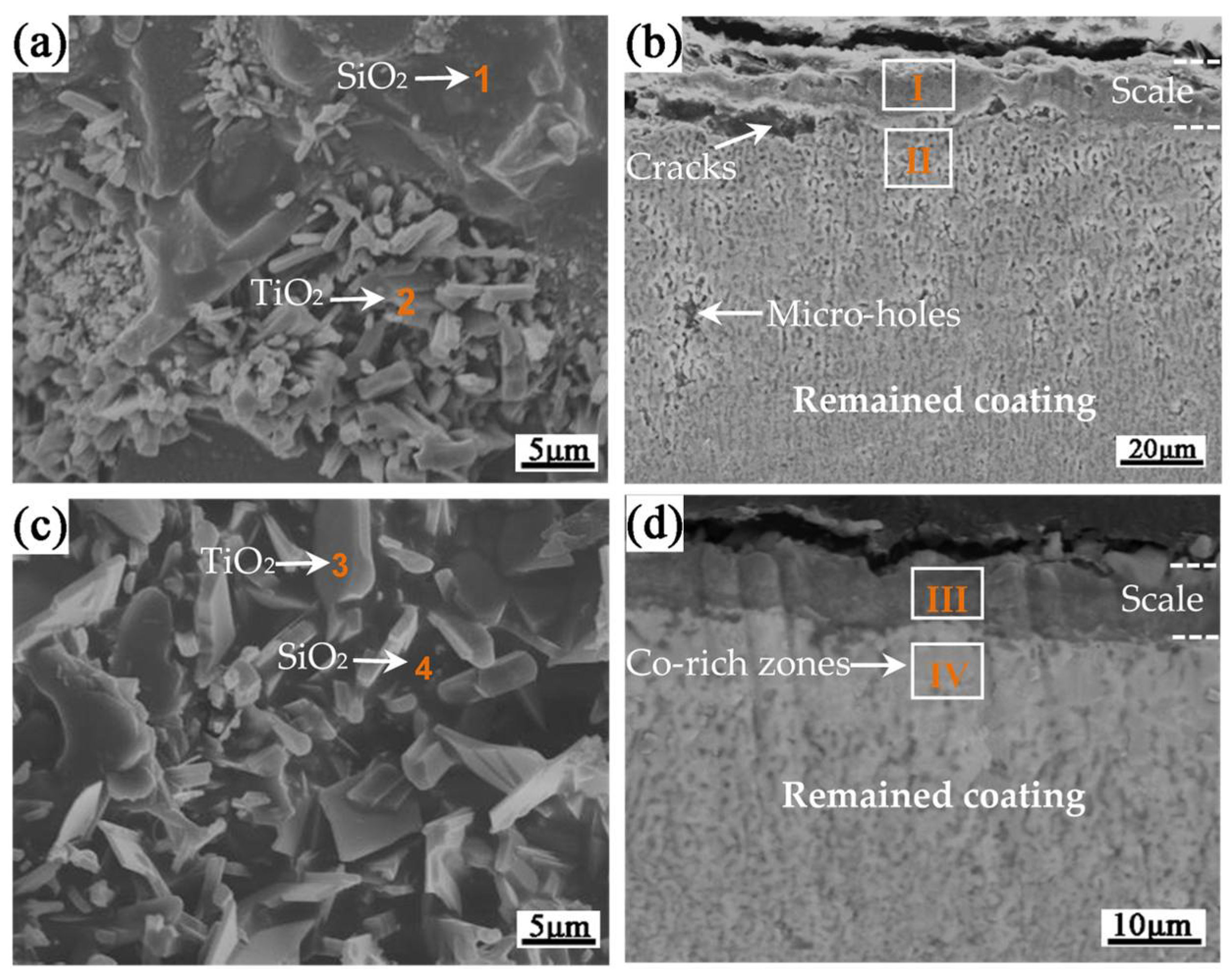
| Points/Areas | Composition (at.%) | |||||
|---|---|---|---|---|---|---|
| Si | Ti | Al | Nb | Co | O | |
| 1 | 22.3 | 5.2 | 2.6 | 2.1 | / | 67.8 |
| 2 | 3.6 | 23.3 | 3.4 | 2.8 | / | 66.9 |
| 3 | 24.2 | 3.4 | 3.2 | 1.5 | 0.3 | 67.4 |
| 4 | 4.2 | 21.9 | 3.6 | 2.0 | 0.8 | 67.8 |
| I | 11.2 | 12.7 | 7.1 | 1.9 | 67.1 | |
| II | 44.8 | 39.6 | 1.9 | 13.7 | / | / |
| III | 13.0 | 9.5 | 8.2 | 2.1 | 0.5 | 66.7 |
| IV | 47.1 | 32.6 | 1.6 | 11.3 | 7.4 | / |
Disclaimer/Publisher’s Note: The statements, opinions and data contained in all publications are solely those of the individual author(s) and contributor(s) and not of MDPI and/or the editor(s). MDPI and/or the editor(s) disclaim responsibility for any injury to people or property resulting from any ideas, methods, instructions or products referred to in the content. |
© 2023 by the authors. Licensee MDPI, Basel, Switzerland. This article is an open access article distributed under the terms and conditions of the Creative Commons Attribution (CC BY) license (https://creativecommons.org/licenses/by/4.0/).
Share and Cite
Tian, J.; Zhang, C.; Lv, W.; Li, X.; Tian, W. Structure and High-Temperature Oxidation Performance of Si-Co Diffusion Coatings Prepared on a TiAl-Nb Alloy. Coatings 2023, 13, 1427. https://doi.org/10.3390/coatings13081427
Tian J, Zhang C, Lv W, Li X, Tian W. Structure and High-Temperature Oxidation Performance of Si-Co Diffusion Coatings Prepared on a TiAl-Nb Alloy. Coatings. 2023; 13(8):1427. https://doi.org/10.3390/coatings13081427
Chicago/Turabian StyleTian, Jin, Conghui Zhang, Wei Lv, Xuan Li, and Wei Tian. 2023. "Structure and High-Temperature Oxidation Performance of Si-Co Diffusion Coatings Prepared on a TiAl-Nb Alloy" Coatings 13, no. 8: 1427. https://doi.org/10.3390/coatings13081427
APA StyleTian, J., Zhang, C., Lv, W., Li, X., & Tian, W. (2023). Structure and High-Temperature Oxidation Performance of Si-Co Diffusion Coatings Prepared on a TiAl-Nb Alloy. Coatings, 13(8), 1427. https://doi.org/10.3390/coatings13081427