Abstract
Titanium alloys are extensively utilized in the aerospace industry due to their exceptional properties, encompassing high specific strength and corrosion resistance. Nevertheless, these alloys present inherent challenges as difficult-to-machine materials characterized by low thermal conductivity and high chemical reactivity. The machining of titanium alloys often gives rise to elevated cutting forces and temperatures, thereby resulting in compromised machining quality and substantial tool wear. This study explores the influence of the cutting-edge shape factor on tool performance and optimizes the cutting-edge structure through finite element simulation. Remarkably, the cutting performance of the tool demonstrates significant enhancement following cutting-edge passivation. Alterations in the geometric shape of the cutting-edge after passivation exert a notable impact on the tool’s cutting performance, with a superior performance observed for shape factor K > 1 compared to alternative edge structures. Additionally, numerical simulation is employed to analyze the influence of passivation values Sγ and Sα on cutting force and temperature, which are crucial factors affecting cutting performance. The results underscore the significant impact of Sγ on cutting force and temperature. Furthermore, within the confines of maintaining an identical shape factor K, the blade segment group featuring Sγ = 40 μm and Sα = 25 μm exhibits the lowest maximum cutting temperature, thereby indicating the optimal tool design attainable through this study.
1. Introduction
Titanium alloys possess excellent properties, such as high specific strength, corrosion resistance, and low-temperature toughness, making them a preferred choice for key components in aerospace engines [1,2,3]. The use of titanium alloys not only effectively prolongs the service life of the parts but also reduces the weight of the parts due to their low density, leading to a reduction in fuel consumption and a significant decrease in costs, while improving flight performance [4,5,6]. However, as the performance requirements for aviation engines continue to increase, higher demands are placed on their materials and manufacturing techniques. Titanium alloys, with their low thermal conductivity, small elastic modulus, and small deformation coefficient, are typical difficult-to-machine materials. During the cutting process of titanium alloys, severe material deformation and heat accumulation near the cutting-edge often occur, leading to tool wear and thus, affecting the machining quality [7].
Tool material, coating technology, and cutting-edge preparation techniques are important factors that affect the cutting performance of tools. With the development of mechanical manufacturing, cutting-edge preparation techniques have received great attention in the tool manufacturing industry [8,9]. These techniques can meet specific geometric shape requirements and solve microscopic geometric defects on the tool surface, effectively improving the tool’s service life and the machining quality of workpieces. Currently, the passivation method is commonly used to prepare cutting edges. However, the microscopic geometry of the tool edge obtained after passivation treatment is not identical, and the edge shape is not uniformly a regular transition radius [10]. The cutting edge of a tool plays a primary cutting role in machining. During the cutting process, the structural form of the cutting edge is directly related to the cutting performance and tool life. The geometric shape of the cutting edge directly affects the force-heat characteristics of the tool. When cutting workpieces, changes in the cutting-edge structure can alter the contact area between the tool and workpiece, leading to changes in cutting force [11]. Tugrul et al. [12] analyzed the influence of the blade edge shape on cutting force and surface integrity during the turning of AISIH13. It was found that reasonable blade edge shape parameters are beneficial for reducing surface roughness and cutting force in the machined surface. Pham and Tchigirinsky [13] revealed the correlation between tool wear patterns and the thermal–physical properties of materials, indicating that besides mechanical loads, thermal loads are also significant influencing factors on tool wear. Uhlmann et al. [14] used the passivation method to passivate the cutting edge of the tool and studied the influence of passivation parameters on tool wear. The study further verified that cutting with passivated tools can slow down the rate of wear. Alterations in the cutting edge can also cause changes in the extrusion and frictional action of the cutting edge on the workpiece, affecting changes in cutting temperature. In metal cutting processes, changes in physical quantities such as cutting force and cutting temperature can cause varying degrees of impact on tool cutting stability, tool life, and workpiece machining quality. Therefore, in cutting titanium alloys with a tool, the cutting-edge structure is a key influencing factor that affects both tool life and machining quality.
Denkena [15,16,17] proposed the shape factor method, usually referred to as the K-factor method. This method uses five parameters to determine the geometric shape of the cutting edge, as shown in Figure 1. The contour lines of the front and back surfaces are extended, and the intersection point of the extension lines is defined as the hypothetical cutting tip. The distance from the virtual cutting tip to the separation point on the front surface is defined as Sγ, which is called the front surface edge segment value. The distance from the separation point on the back surface to the cutting tip is defined as Sα, which is called the back surface edge segment value of the cutting tool. The geometric shape of the cutting edge is described by the ratio of Sγ to Sα, denoted as K, which is called the shape factor. If K = 1, the cutting edge of the tool is symmetrical; when K < 1, it means that the cutting edge of the tool tends to the back surface, which is called the waterfall type cutting edge; when K > 1, the shape of the cutting edge of tool inclines towards the front surface and is called the trumpet type cutting edge.
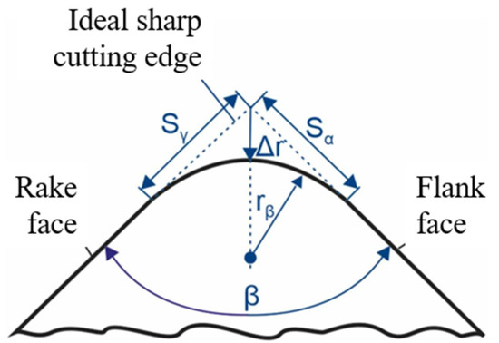
Figure 1.
Schematic representation of the K-factor method [17].
Due to the low thermal conductivity of titanium alloys, a large amount of heat accumulation is generated during the cutting process, which leads to an increase in temperature near the cutting edge of the tool, affecting the cutting performance and shortening the tool life. Therefore, in the study of the shape factors affecting tool cutting performance, it is necessary to monitor the cutting temperature [18,19]. However, there is still a great difficulty in accurately measuring the cutting temperature and its distribution in the cutting zone in both turning and milling processes [20]. With the development of computer technology, the numerical simulation analysis method has attracted the attention of many scholars in engineering [21,22,23,24,25,26]. The finite element method (FEM) has the advantages of high accuracy, low cost, and high efficiency. Compared with traditional analytical models, FEM is closer to the cutting deformation, heat transfer, and heat distribution in actual cutting processes. It is widely used in the field of metal cutting to study the material deformation process and the various factors that affect cutting. Aydın and Köklü [27,28] conducted the numerical study of chip formation and cutting force in high-speed machining of Ti6Al4V bases on FEM and explored the material removal mechanisms, such as ductile fracture, with more details.
Thus, in this paper, the objective it is to investigate the influence of cutting-edge shape factors on cutting performance. The Ti6Al4V is taken as the target, and proper cutting model with hard alloy tools is established using ABAQUS software (Dassault Systèmes, Paris, France) (version 2021). The 3D model is simplified into a 2D orthogonal cutting model. Different cutting-edge shapes are used in cutting simulations to investigate the changes in cutting physical quantities such as cutting force and temperature at the cutting edge during the cutting process. This analysis aims to improve the understanding of the edge mechanism, enhance tool life and machining quality, and provide theoretical support for studying tool wear mechanisms.
2. Model Development
2.1. Model Geometry and Boudary Conditions
The metal cutting process is a complex interaction between the cutting tool and the workpiece and is influenced by multiple factors. When conducting FEM analysis, it is advantageous to simplify the metal cutting process by only considering the major influential factors and ignoring some of the minor factors. Therefore, the actual 3D cutting process can be transformed into a 2D orthogonal plane strain problem for FEM analysis. The schematic diagram of the 2D orthogonal turning model used in this study is shown in Figure 2a. The workpiece size is 10 mm × 3.5 mm and is considered a deformable body. The tool is 2 mm wide and 3 mm high, with a rake angle of 5° and a clearance angle of 10°. In this study, only the cutting force and temperature were analyzed, and the tool was assumed to be rigid. As the focus of this paper is to investigate the effect of the shape factor of the cutting edge on the cutting performance of the tool, the geometric parameters of the tool edge were not fixed during FEM modeling. The cutting speed was set at v = 30 m/min and the cutting depth was fixed at ap = 1 mm. The initial temperature was set at 20 °C.
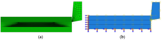
Figure 2.
(a) Model geometry and meshing method; (b) boundary conditions.
The ALE adaptive meshing method is used to partition the finite element model into meshes [29]. The workpiece is divided into three parts, and only the cutting area is meshed with high density. The middle part serves as a transitional area to prevent excessive distortion of the mesh during analysis. The mesh in the cutting layer is denser than that far from it, which ensures simulation accuracy while reducing computation time. Additionally, in actual cutting processes, the tool interacts with the workpiece, and the tool tip is involved in cutting. Therefore, during mesh partitioning, the front and back tool surfaces are seeded with an offset to make the mesh denser at the tool tip and sparser elsewhere, as shown in Figure 2. This meshing approach is more realistic. Three mesh sizes of 0.05, 0.1, and 0.2 mm were tested for mesh independence in the simulation cutting model. The calculation results of all three mesh sizes had deviations less than 5%, and a mesh size of 0.1 mm was chosen for subsequent simulation calculations, as shown in Figure 2a. To extract the cutting force and temperature values more accurately during the cutting process, the mesh elements of the tool and workpiece are coupled with a four-node plane strain element with temperature-displacement. The friction coefficient between the tool and workpiece in the finite element model is selected as 0.2 [30].
In addition, the boundary conditions in the finite element simulation are shown in Figure 2b. In the finite element analysis, to achieve the relative motion between the tool and the workpiece, the workpiece is fixed in place while the tool moves. Therefore, constraints are set on the left and bottom sides of the workpiece to limit the movement in the x and y directions. A velocity of 30 m/min to the left is applied to the reference point of the tool to simulate the cutting process.
2.2. Material Constitutive Model
During metal cutting, the mechanical properties of the material undergo dynamic changes accompanied by significant elastic–plastic deformation. It is difficult to describe the performance characteristics of all materials using a fixed material constitutive relationship. Therefore, in order to improve the accuracy of simulation calculations, a dynamic constitutive model must be selected in cutting simulation. Additionally, in the cutting process, materials often undergo elastic–plastic deformation under large strains, high strain rates, and cutting temperature conditions. This requires that when selecting the constitutive model, the influence of strain, strain rate, and temperature on material flow must be fully reflected [31]. Choosing a reasonable constitutive model can result in more accurate simulation results. Currently, there are two main types of material constitutive models commonly used in metal cutting simulations: empirical constitutive models such as the Johnson–Cook model (J–C model), and physics-based constitutive models such as the Zerilli–Armstrong model.
Among them, the J–C constitutive model can fully reflect the strain hardening, strain rate hardening, and thermal softening effects in the cutting process and more accurately describe the deformation of metallic materials. Therefore, in this study, the J–C material constitutive model was selected to simulate the metal cutting process. The mathematical relationship of the J–C constitutive model is shown below [32]:
The explanations of the relevant parameters of the J–C material constitutive equation can be found in Ref. [32] and user manual in ABAQUS, and in this paper the values of these parameters in Equation (1) are shown in Table 1. The properties of the hard alloy cutting tool and Ti6Al4V titanium alloy material are shown in Table 2.

Table 1.
J–C model parameters of Ti6Al4V material [33].
Table 2.
Material properties of workpiece and cutting tool in simulation [33].
3. Results and Discussion
To investigate the influence of cutting-edge geometry on cutting performance, other factors which may interfere with the research conclusions, i.e., other than the edge shape, need to be set to reasonable values. Based on the simulation analysis of cutting parameters, a cutting speed of v = 30 m/min and a cutting depth of ap = 1 mm were determined for the following simulation studies. Other model parameters were set as follows: a 5° rake angle; a 10° relief angle; and a 0° flank angle. To study the influence of cutting-edge geometry, simulations were first performed using multiple data points of shape factor ranging from K = 0.3 to K = 2.4 to analyze the effect of different K values on cutting performance and to obtain the ideal range of K. Next, different edge shapes were formed by using different edge segment values, Sγ and Sα. Using a fixed value of Sγ = 40 μm, Sα was set from 10 to 75 μm to analyze the influence of Sα on cutting performance. Similarly, using a fixed value of Sα = 40 μm, Sγ was set from 10 to 75 μm to study the influence of Sγ on cutting performance while keeping cutting conditions and parameters the same. Furthermore, in simulation, the cutting force is the average value of the contact zone between the cutting tool and workpiece, and the cutting temperature is the highest temperature in the contact zone between the cutting tool and workpiece.
3.1. Effect of Shape Factor on Cutting Performance
Figure 3 shows the influence curve of cutting force with the change of shape factor K. As shown in Figure 3a,b, it can be observed that within the range of K < 1, the cutting force F increases with the increase in shape factor K. Within the range of 1 < K < 2.3, the cutting force F first decreases and then increases with the increase in shape factor K. When K = 2, the cutting force F is the smallest.
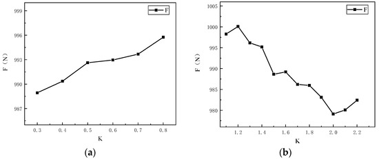
Figure 3.
Effect of shape factor K on cutting force: (a) K < 1; (b) K > 1.
Based on the simulation results, the influence curve of the shape factor K on cutting temperature is obtained. Analysis of Figure 4a,b reveals that within the K < 1 range, the cutting temperature first increases and then decreases with the increase in K; while within the K > 1 range, the cutting temperature first decreases and then increases with the increase in K. Within the range of 0.3 < K < 2.3, K = 0.7 corresponds to the highest cutting temperature among all K values studied, while K = 1.7 corresponds to the lowest maximum cutting temperature. Within the range of 1.6 < K < 1.9, the cutting temperature is the lowest among all studied ranges, which minimizes the possibility of adhesive wear of the tool. During the cutting process with a tool where 0.5 < K < 0.7, the maximum cutting temperature exceeds 800 °C, which exacerbates tool wear and affects tool cutting performance. When K > 1, the cutting temperature is generally lower, all below 800 °C, and it is less likely to cause tool wear compared to other cases, thus achieving better cutting performance of the tool.
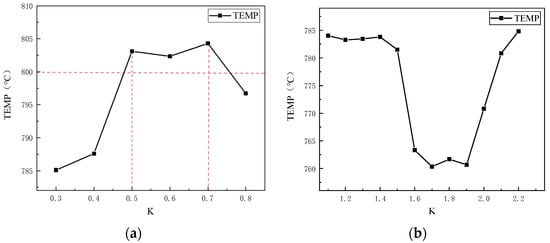
Figure 4.
Effect of shape factor K on cutting temperature: (a) K < 1; (b) K > 1.
Based on comprehensive analysis, changes in the geometry of the cutting edge will result in variations in cutting forces and temperatures during the cutting process. Compared with the effect of K on cutting forces, K has a more significant impact on cutting temperatures. When K < 1, the highest cutting temperature can exceed 800 °C, while the cutting heat generated by the K > 1 tool is lower than that of K < 1. Among them, in the range of 1.6 < K < 1.9, the highest cutting temperature is the lowest among all simulation results. Considering the decisive impact of cutting heat on tool wear, cutting temperature is the primary factor affecting tool cutting performance. Therefore, based on the study of the effects of different shape factors K on tool cutting performance, the preliminary conclusion is that the cutting performance of tools with K > 1 is better, and tool wear is less affected by cutting edge.
3.2. Effect of Sγ on Cutting Performance
The fixed value of Sα is 40 μm, and multiple different values of Sγ ranging from 10 μm to 75 μm are selected to investigate the influence of the value of the front edge segment on the cutting performance of the tool in the simulation analysis. The cutting force shows a decreasing trend in fluctuation with the increase in Sγ, as shown in Figure 5. This is because as Sγ increases, the contact area between the chip and the front edge surface increases, and under the same cutting force, the cutting force per unit area of the front edge surface participating in the cutting work decreases accordingly. When Sγ = 70 μm or K = 1.75, with Sα fixed at 40 μm, the cutting force during the cutting process is minimized.
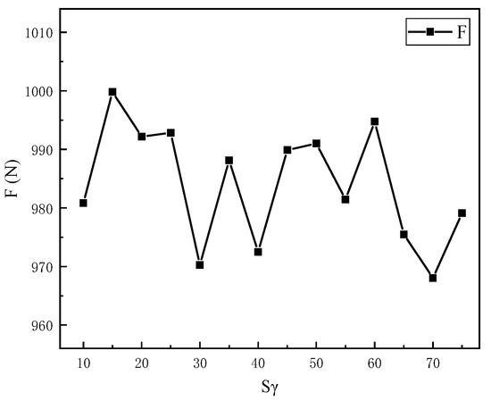
Figure 5.
Effect of Sγ on cutting force.
As shown in Figure 6, the cutting temperature exhibits an upward and downward fluctuating trend as Sγ increases, with an overall temperature below 800 °C. At Sγ = 50 μm, i.e., K = 1.2, the cutting temperature is the lowest. This is because different cutting-edge structures have two opposite effects on cutting temperature during the cutting process. On the one hand, as Sγ increases, the actual rake angle involved in the cutting work is a negative rake angle and increases gradually, resulting in an increase in the compressive and frictional forces acting on the front cutting edge, which exacerbates material cutting deformation and generates more heat. Due to the low thermal conductivity and poor heat dissipation characteristics of titanium alloys, the heat is not easily dissipated, resulting in an increase in cutting temperature. On the other hand, as Sγ increases, the thermal volume and heat dissipation area of the tool’s front face increase, and hard alloy tools have good thermal conductivity, which can diffuse the heat generated by the tool tip during cutting to the entire tool, slowing down the temperature rise in the cutting-edge region. These two opposite effects cause the cutting temperature to fluctuate as Sγ increases.
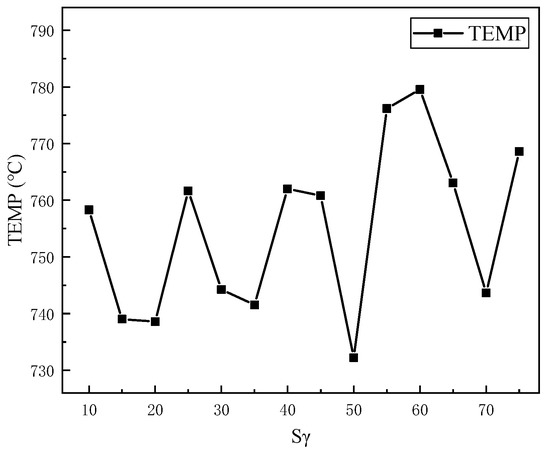
Figure 6.
Effect of Sγ on cutting temperature.
Based on the comprehensive analysis of the effects of the front cutting edge segment value, Sγ, on the three key factors of cutting force, cutting temperature, and force amplitude, in order to ensure good cutting performance of the tool, the cutting zone should not be too large, the cutting temperature should be as low as possible, the fluctuation of cutting force should be minimized, and tool vibration should be reduced. The intersection of the reasonable values for the three factors yields a range of 50~70 μm for the front cutting-edge segment value, Sγ, with a shape factor of 1.25 < K < 1.75. In this range, the overall cutting performance of the tool is better.
3.3. Effect of Sα on Cutting Performance
The influence of the front cutting-edge segment value, Sα, on cutting force, cutting temperature, and force amplitude was studied while keeping Sγ fixed at 40 μm in the range of 10–65 μm. The influence of Sα on cutting force is shown in Figure 7. It can be observed that with the increase in Sα, the cutting force first decreases and then increases, but the overall change in cutting force is not significant, fluctuating around 10 N. The choice of different rear cutting edge segment lengths has little effect on the cutting force during the cutting process, and there is not much difference in the impact on tool wear. As Sα increases, the cutting temperature shows an upward trend, as shown in Figure 8. When Sα is 25 μm, the maximum cutting temperature on the tool during the cutting process is significantly lower than other conditions, indicating that Sα = 25 μm, i.e., K = 1.6, has less impact on the tool temperature and lower likelihood of tool wear, resulting in better cutting performance. This is because as Sα increases, the actual negative rake angle involved in the cutting work decreases, the plastic deformation of the workpiece material increases at the first deformation zone, and the resulting deformation heat increases. Moreover, as Sα decreases, the contact area between the rear cutting edge and the machined surface decreases, and the workpiece is subjected to less compression and friction, making it less likely to deform or rebound.
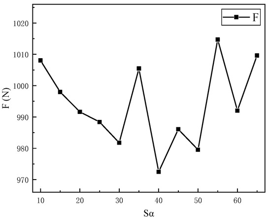
Figure 7.
Effect of Sα on cutting force.

Figure 8.
Effect of Sα on cutting temperature.
After a comprehensive analysis of the influence of the back rake angle, Sα, on the three factors mentioned above, to ensure that the cutting zone is not too large, the probability of tool chipping should be reduced; the cutting temperature should be as low as possible to reduce tool wear; and the fluctuation of cutting force should be minimized to reduce tool vibration. The intersection of the reasonable values of these three factors yields a more reasonable back rake angle, Sα, of 25 μm, with a shape factor of K = 1.6, which results in good overall cutting performance of the tool.
3.4. Effect of Sγ/Sα on Cutting Performance
Based on the above research and analysis, it is found that in the range of 1 < K < 2, the cutting force is suitable, the cutting temperature is low, the cutting force fluctuation is not significant, and the tool is not easily worn, resulting in a better surface quality of the machined part. In addition, when different combinations of Sγ and Sα are used to form different cutting-edge shapes for simulation analysis, it is found that the overall cutting performance of the tool is better when Sα is fixed at 40 μm and Sγ is in the range of 50–70 μm, or when Sγ is fixed at 40 μm and Sα is 25 μm. However, the above research only analyzes a single factor. In order to study whether different combinations of front and back cutting-edge segment values have an impact on tool cutting performance when the shape factor K is fixed, Sγ/Sα combinations were selected with K = 1.6 fixed, and the collected data are shown in Figure 9.

Figure 9.
Effect of different Sγ/Sα combinations on cutting performance: (a) cutting force; (b) cutting temperature.
From the perspective of the influence curve of cutting force, the combination of Sγ/Sα = 56/35 μm results in the minimum cutting force; from the perspective of the influence curve of cutting temperature, the combination of Sγ/Sα = 40/25 μm results in the lowest cutting temperature. Through a comprehensive analysis of the impact of each combination on cutting performance, it can be observed that the cutting force for Sγ/Sα = 56/35 μm is 10 N less than that of Sγ/Sα = 40/25 μm, but the maximum cutting temperature is 34 °C higher and approaches 800 °C. Considering that cutting temperature has a greater impact on tool wear than cutting force, the combination of Sγ = 40 μm and Sα = 25 μm on the front and back rake faces, respectively, leads to better cutting performance when K = 1.6.
4. Conclusions
This paper utilized FEM simulation to examine the influence of cutting-edge shape factor on cutting performance. The findings are summarized as follows:
(1) Analysis of cutting force and temperature revealed that changes in the cutting-edge structure impact tool performance. When the shape factor is K > 1, the overall cutting force decreases compared to K < 1. The shape factor has minimal effect on cutting force fluctuations, while the maximum cutting temperature decreases as K increases, reaching the lowest point at K = 1.7.
(2) Variations in the front tool face segment value, Sγ, affect the actual negative front rake angle and plastic deformation in the first deformation zone, influencing heat generation. Changes in the back tool face segment value, Sα, impact the contact area between the back tool face and the workpiece surface, affecting extrusion, friction, cutting force, and temperature. Comparing their effects, Sγ demonstrates a greater impact on cutting performance than Sα.
(3) By maintaining a fixed shape factor of K = 1.6, different cutting-edge structures were investigated. It was found that the combination of Sγ = 40 μm and Sα = 25 μm resulted in the lowest maximum cutting temperature, indicating optimal cutting performance for the tool.
Author Contributions
Conceptualization, Z.Y.; Data curation, Z.Y.; Investigation, Z.Y. and X.Y.; Supervision, H.Y.; Writing—original draft, Z.Y.; Writing—review & editing, H.Y. All authors have read and agreed to the published version of the manuscript.
Funding
This research was funded by Lishui Science and Technology Plan Project (Grant No. 2022ZDYF04, 2022SJC003), Natural Science Foundation of Zhejiang Province (Grant No. LZ21F020003, LY20E050002), Lishui Science and Technology Plan Project (Grant No. 2020TPY02) and Lishui University Discipline Construction Project (Funding Discipline Name: Mechanical Engineering).
Institutional Review Board Statement
Not applicable.
Informed Consent Statement
Not applicable.
Data Availability Statement
Not applicable.
Conflicts of Interest
The authors declare that the research was conducted in the absence of any commercial or financial relationships that could be construed as a potential conflict of interest.
References
- Zhang, L.; Yuan, Z.; Qi, Z.; Cai, D.; Cheng, Z.; Qi, H. CFD-based study of the abrasive flow characteristics within constrained flow passage in polishing of complex titanium alloy surfaces. Powder Technol. 2018, 333, 209–218. [Google Scholar] [CrossRef]
- Yuan, H.; Yang, W.; Zhang, L.; Hong, T. Model Development of Stress Intensity Factor on 7057T6 Aluminum Alloy Using Extended Finite Element Method. Coatings 2023, 13, 581. [Google Scholar] [CrossRef]
- Xie, X.; Zhang, L.; Zhu, L.; Li, Y.; Hong, T.; Yang, W.; Shan, X. State of the Art and Perspectives on Surface-Strengthening Process and Associated Mechanisms by Shot Peening. Coatings 2023, 13, 859. [Google Scholar] [CrossRef]
- Yang, X.; Wang, F.-H.; Wang, W.-L.; Liu, S.-F.; Chen, Y.-Q.; Tang, H.-P. Comparison of two-step surface treatment on surface roughness and corrosion resistance of TC4 alloy parts prepared by SLM and SEBM. J. Alloy. Compd. 2022, 921, 165929. [Google Scholar] [CrossRef]
- Charee, W.; Qi, H.; Zhu, H.; Saetang, V. Coaxial water and air jet–assisted laser micromachining of titanium. Int. J. Adv. Manuf. Technol. 2022, 121, 5605–5616. [Google Scholar] [CrossRef]
- Tangwarodomnukun, V.; Kringram, S.; Zhu, H.; Qi, H.; Rujisamphan, N. Fabrication of superhydrophobic surface on AISI316L stainless steel using a nanosecond pulse laser. Proc. Inst. Mech. Eng. Part B J. Eng. Manuf. 2022, 236, 680–693. [Google Scholar] [CrossRef]
- Chakradhar, B.; Singaravel, B.; Ugrasen, G.; Kiran Kumar, A. Prediction of cutting forces using MRA, GMDH and ANN techniques in micro end milling of titanium alloy. Mater. Today Proc. 2023, 72, 1943–1949. [Google Scholar] [CrossRef]
- Hartig, J.; Kirsch, B.; Zimmermann, M.; Aurich, J.C. Cutting edge preparation with elastic bonded diamond grinding wheels: Influence of the interaction of metalworking fluid and grinding wheel on the grinding wheel properties and preparation result. CIRP J. Manuf. Sci. Technol. 2022, 38, 350–371. [Google Scholar] [CrossRef]
- Zimmermann, M.; Kirsch, B.; Kang, Y.; Herrmann, T.; Aurich, J.C. Influence of the laser parameters on the cutting edge preparation and the performance of cemented carbide indexable inserts. J. Manuf. Process. 2020, 58, 845–856. [Google Scholar] [CrossRef]
- Aurich, J.C.; Effgen, C.; Kirsch, B. Cutting edge preparation with elastic bonded superabrasive grinding wheels. CIRP Ann. 2016, 65, 329–332. [Google Scholar] [CrossRef]
- Bouzakis, K.D.; Bouzakis, E.; Kombogiannis, S.; Makrimallakis, S.; Skordaris, G.; Michailidis, N.; Charalampous, P.; Paraskevopoulou, R.; M’Saoubi, R.; Aurich, J.C.; et al. Effect of cutting edge preparation of coated tools on their performance in milling various materials. CIRP J. Manuf. Sci. Technol. 2014, 7, 264–273. [Google Scholar] [CrossRef]
- Özel, T.; Hsu, T.-K.; Zeren, E. Effects of cutting edge geometry, workpiece hardness, feed rate and cutting speed on surface roughness and forces in finish turning of hardened AISI H13 steel. Int. J. Adv. Manuf. Technol. 2005, 25, 262–269. [Google Scholar] [CrossRef]
- Pham, H.T.; Tchigirinsky, J.L. Analysis of mechanism of carbide tool wear and control by wear process. MATEC Web Conf. 2017, 129, 01058. [Google Scholar] [CrossRef]
- Uhlmann, E.; Eulitz, A.; Dethlefs, A. Discrete Element Modelling of Drag Finishing. Procedia CIRP 2015, 31, 369–374. [Google Scholar] [CrossRef]
- Denkena, B.; Köhler, J.; Ventura, C.E.H. Customized cutting edge preparation by means of grinding. Precis. Eng. 2013, 37, 590–598. [Google Scholar] [CrossRef]
- Denkena, B.; Biermann, D. Cutting edge geometries. CIRP Ann. 2014, 63, 631–653. [Google Scholar] [CrossRef]
- Denkena, B.; Lucas, A.; Bassett, E. Effects of the cutting edge microgeometry on tool wear and its thermo-mechanical load. CIRP Ann. 2011, 60, 73–76. [Google Scholar] [CrossRef]
- Jamil, M.; He, N.; Zhao, W.; Kumar Gupta, M.; Mashood Khan, A. Novel approach of cutting temperature measurement in sustainable milling of Ti-6Al-4V alloy. Measurement 2023, 214, 112837. [Google Scholar] [CrossRef]
- Wang, Y.; Wang, Z.; Ni, P.; Wang, D.; Lu, Y.; Lu, H.; Guo, S.; Chen, Z. Experimental and Numerical Study on Regulation of Cutting Temperature during the Circular Sawing of 45 Steel. Coatings 2023, 13, 758. [Google Scholar] [CrossRef]
- Aydın, M.; Köklü, U. Analysis of flat-end milling forces considering chip formation process in high-speed cutting of Ti6Al4V titanium alloy. Simul. Model. Pract. Theory 2020, 100, 102039. [Google Scholar] [CrossRef]
- Qi, H.; Wen, D.; Yuan, Q.; Zhang, L.; Chen, Z. Numerical investigation on particle impact erosion in ultrasonic-assisted abrasive slurry jet micro-machining of glasses. Powder Technol. 2017, 314, 627–634. [Google Scholar] [CrossRef]
- Zhang, L.; Ji, R.; Fu, Y.; Qi, H.; Kong, F.; Li, H.; Tangwarodomnukun, V. Investigation on particle motions and resultant impact erosion on quartz crystals by the micro-particle laden waterjet and airjet. Powder Technol. 2020, 360, 452–461. [Google Scholar] [CrossRef]
- Qi, H.; Qin, S.; Cheng, Z.; Zou, Y.; Cai, D.; Wen, D. DEM and experimental study on the ultrasonic vibration-assisted abrasive finishing of WC-8Co cemented carbide cutting edge. Powder Technol. 2021, 378, 716–723. [Google Scholar] [CrossRef]
- Qi, H.; Wang, Y.; Qi, Z.; Shi, L.; Fang, Z.; Zhang, L.; Riemer, O.; Karpuschewski, B. A Novel Grain-Based DEM Model for Evaluating Surface Integrity in Scratching of RB-SiC Ceramics. Materials 2022, 15, 8486. [Google Scholar] [CrossRef] [PubMed]
- Qian, H.; Chen, M.; Qi, Z.; Teng, Q.; Qi, H.; Zhang, L.; Shan, X. Review on Research and Development of Abrasive Scratching of Hard Brittle Materials and Its Underlying Mechanisms. Crystals 2023, 13, 428. [Google Scholar] [CrossRef]
- Ji, R.; Qi, Z.; Chen, J.; Zhang, L.; Lin, K.; Lu, S.; Li, Y. Numerical and Experimental Investigation on the Abrasive Flow Machining of Artificial Knee Joint Surface. Crystals 2023, 13, 430. [Google Scholar] [CrossRef]
- Aydın, M.; Köklü, U. Identification and modeling of cutting forces in ball-end milling based on two different finite element models with Arbitrary Lagrangian Eulerian technique. Int. J. Adv. Manuf. Technol. 2017, 92, 1465–1480. [Google Scholar] [CrossRef]
- Aydın, M. Numerical study of chip formation and cutting force in high-speed machining of Ti-6Al-4V bases on finite element modeling with ductile fracture criterion. Int. J. Mater. Form. 2021, 14, 1005–1018. [Google Scholar] [CrossRef]
- Dobrev, V.; Knupp, P.; Kolev, T.; Mittal, K.; Rieben, R.; Tomov, V. Simulation-driven optimization of high-order meshes in ALE hydrodynamics. Comput. Fluids 2020, 208, 104602. [Google Scholar] [CrossRef]
- Sterle, L.; Pušavec, F.; Kalin, M. Determination of friction coefficient in cutting processes: Comparison between open and closed tribometers. Procedia CIRP 2019, 82, 101–106. [Google Scholar] [CrossRef]
- Guan, Q.; Lu, S.; Lu, Y.; Li, J. Study on the modified power-law constitutive model for the FEM cutting simulation of Inconel 625 deposited metal using the electroslag welding process. J. Manuf. Process. 2022, 81, 881–892. [Google Scholar] [CrossRef]
- Johnson, G.R.; Cook, W.H. Fracture characteristics of three metals subjected to various strains, strain rates, temperatures and pressures. Eng. Fract. Mech. 1985, 21, 31–48. [Google Scholar] [CrossRef]
- Kugalur-Palanisamy, N.; Rivière-Lorphèvre, E.; Ducobu, F.; Arrazola, P.-J. Influence of the Choice of the Parameters on Constitutive Models and their Effects on the Results of Ti6Al4V Orthogonal Cutting Simulation. Procedia Manuf. 2020, 47, 458–465. [Google Scholar] [CrossRef]


Disclaimer/Publisher’s Note: The statements, opinions and data contained in all publications are solely those of the individual author(s) and contributor(s) and not of MDPI and/or the editor(s). MDPI and/or the editor(s) disclaim responsibility for any injury to people or property resulting from any ideas, methods, instructions or products referred to in the content. |
© 2023 by the authors. Licensee MDPI, Basel, Switzerland. This article is an open access article distributed under the terms and conditions of the Creative Commons Attribution (CC BY) license (https://creativecommons.org/licenses/by/4.0/).