Abstract
Calcium phosphate/Bioglass composite coatings on AISI 316L were investigated with regard to their potential role as a beneficial coating for orthopedic implants. These coatings were realized by the galvanic co-deposition of calcium phosphate compounds and Bioglass particles. A different amount of Bioglass 45S5 was used to study its effect on the performance of the composite coatings. The morphology and chemical composition of the coatings were investigated before and after their aging in simulated body fluid. The coatings uniformly covered the AISI 316L substrate and consisted of a brushite and hydroxyapatite mixture. Both phases were detected using X-ray diffraction and Raman spectroscopy. Additionally, both analyses revealed that brushite is the primary phase. The presence of Bioglass was verified through energy-dispersive X-ray spectroscopy, which showed the presence of a silicon peak. During aging in simulated body fluid, the coating was subject to a dynamic equilibrium of dissolution/reprecipitation with total conversion in only the hydroxyapatite phase. Corrosion tests performed in simulated body fluid at different aging times revealed that the coatings made with 1 g/L of Bioglass performed best. These samples have a corrosion potential of −0.068V vs. Ag/AgCl and a corrosion current density of 8.87 × 10⁻⁷ A/cm2. These values are better than those measured for bare AISI 316L (−0.187 V vs. Ag/AgCl and 2.52 × 10⁻⁶ A/cm2, respectively) and remained superior to pure steel for all 21 days of aging. This behavior indicated the good protection of the coating against corrosion phenomena, which was further confirmed by the very low concentration of Ni ions (0.076 ppm) released in the aging solution after 21 days of immersion. Furthermore, the absence of cytotoxicity, verified through cell viability assays with MC3T3-E1 osteoblastic cells, proves the biocompatibility of the coatings.
1. Introduction
Ceramic materials are inorganic compounds that have been gradually incorporated into our everyday lives [1,2]. Thanks to their thermal and electrical insulating properties, ceramic materials can be applied as technological solutions in the fields of telecommunications, energy, and the environment [3]. Ceramic materials are popularly used in the field of biomedical applications, and those useful in this field are usually referred to as bioceramics [4,5,6,7].
Bioceramics play a crucial role in tissue engineering and orthopedics because of their chemical inertia and high wettability, favoring proteins and cell adhesion [8,9,10,11]. Therefore, different types of ceramic materials have been studied [12].
Bioceramics can be subdivided into three main groups depending on the interactions between the used materials and the human body. Bioinert ceramics do not interact with the human environment and, therefore, can be incorporated into implanted living bone without presenting any sign of toxicity [13,14]. In contrast, bioactive ceramics possess the ability to initiate a biological response after implantation into the body, such as cell stimulation and stem cell proliferation for the regeneration of damaged tissue or whole organs [15,16,17]. Finally, when in contact with body fluids, bioresorbable ceramics can be fully metabolized, easily dissolved, and subsequently excreted [18,19].
Among the ceramic materials used in biomedical applications, Bioglass (BG) and calcium phosphate (CaP) compounds have found great applications in repairing and reinforcing bone tissue in orthopedics and dentistry [20,21,22,23,24].
Bioglasses are silica-based bioactive ceramics developed in the 1970s by Hench through mixing different oxides using the melt-quenching method [25]. The bioactivity of Bioglass is linked to the chemical composition [23], which, in this case, refers to how easily surface chemical reactions occur, as it can generate a hydroxyapatite layer and promote excellent osseointegration [26]. Specifically, Bioglass with 45–52 wt% SiO2 ensures good adhesion to bone and soft tissue, whereas a content of 52–60 wt% SiO2 only allows for bone adhesion [27,28]. As soon as its SiO2 concentration increases above 60 wt%, Bioglass loses its bioactivity, with a dramatic decrease in terms of osseointegration [29]. Approved by the Food and Drug Administration in 1985, Bioglass® 45S5 (45% SiO2, 24.5% CaO, 24.5% Na2O, and 6% P2O5) has been widely used to repair bone and dental defects [30]. Bioglasses have remarkable osteoconductivity and osteoinductivity properties in that they induce primitive cells to differentiate, forming new bone tissue [30,31]. Baino et al. [32] shed light on the potential of Bioglass, which has not only been used in the field of orthopedics (e.g., as scaffolds for bone regeneration or coatings for orthopedic implants) but also for soft tissue regeneration, ocular implants, wound healing, and percutaneous catheters [33]. Bioglass–polymer composites have also been proposed [34,35,36].
Calcium phosphates are another class of ceramic materials that have been successfully applied in the biomedical field [37,38]. In contrast to Bioglass, calcium phosphate compounds allow for the osteoconduction of pre-differentiated bone cells [21,39,40,41]. A comprehensive overview of calcium-phosphate-based biomaterials in orthopedics was presented by Hou et al. [42], who summarized the advantages and disadvantages of these materials. Since the early 1970s, hydroxyapatite (Ca10(PO4)6(OH)2) has increasingly been utilized in orthopedics since it represents the mineral part of bone tissue [43,44]. Thanks to its great stability [45], it is suitable for the fabrication of scaffolds, bone void fillers, and maxillofacial and dental surgery [42,46]. Despite its weak mechanical strength, hydroxyapatite has largely been utilized as the main biomaterial for the fabrication of coatings in orthopedics [47]. Many studies have demonstrated the improvement of cellular response thanks to this material’s high biocompatibility and enhanced protection against corrosion phenomena [48,49,50]. Moreover, it has been demonstrated that the biological and physicochemical properties of hydroxyapatite can be increased by doping it with various ions such as iron [51], magnesium [52], europium [53], samarium [54], silver [55], and cerium [56].
The properties of pure calcium phosphate compounds and Bioglass are synergically increased in their composites [57]. From a biological point of view, the synergistic action of hydroxyapatite and Bioglass improves cell adhesion and proliferation [58] and promotes osteogenic activity [59]. Moreover, in vitro tests conducted on hydroxyapatite/Bioglass-coated substrates have shown that the presence of the coating remarkably increases cell viability and proliferation compared to no coated metallic surfaces [60,61].
Regarding the deposition methods used for composite coatings, a comprehensive, state-of-the-art technique was proposed by Maximov et al. [62]. These authors reported different kinds of coating deposition techniques. Most of the used methods are characterized by high-vacuum and/or high-temperature steps, such as enameling [63], plasma spray deposition [64], air plasma spraying [65], suspension plasma spraying [66], radio frequency magnetron sputtering [67], laser-pulsed deposition [68], thermal spraying [69], and laser cladding [70]. In addition, these methods are difficult to manage and require the use of specific equipment and specialized personnel. Electrophoretic deposition [71], electrodeposition [72,73], and sol–gel deposition [74,75] represent other methods of deposition that are more user-friendly to perform, but they require the use of specific equipment. Furthermore, typically after electrophoresis, a high-temperature treatment step is required to improve the adhesion strength between the Bioglass coating and the substrate [76].
In this work, galvanic deposition was used to achieve the co-deposition of a calcium phosphate/Bioglass composite coating on 316L stainless steel, constituting the first-ever use of this method for such an application. This substrate was selected from among those usable for orthopedic implants [77] because of its excellent biocompatibility and good mechanical properties [78]. The calcium phosphate/Bioglass composite coating is designed to enhance the biocompatibility of this substrate [79].
Unlike the methods of deposition mentioned earlier, galvanic deposition is a simple technique that does not require a power supply [80]. The galvanic coupling between two metals (a working electrode and a sacrificial anode) plays a crucial role in the process. The metals must be characterized by different values of standard redox potential. In addition, another positive point to highlight is the controllability of the galvanic process since the deposition rate depends on the ratio between anodic and cathodic areas. Using this method, we have obtained different types of coatings on stainless steel [81,82,83,84,85,86,87,88]. The galvanic deposition of brushite on Ti alloy, which was converted into hydroxyapatite through a subsequent hydrothermal treatment, was also reported by Chen et al. [89]. Moreover, this technique can be useful for the fabrication of nanowire arrays via the template-assisted method [90,91,92,93,94]. Galvanic replacement was also used to prepare bimetallic and ternary electrocatalysts for applications in fuel cells and the electrolysis and electrosynthesis reactions [95]. Since it could be considered a spontaneous process, galvanic deposition does not require sophisticated equipment or an experienced operator. In addition, it can be considered an eco-friendly process since a sacrificial anode (e.g. aluminum) can be procured from end-life materials to provide added value to waste. A limitation of this method is that it can only be used for cathodic deposits; moreover, if the deposition parameters are not suitably optimized, the coatings obtained may present numerous defects [96].
In this work, we will attempt to demonstrate that the galvanic method is also useful for achieving the co-deposition of calcium phosphate compounds and Bioglass and that the coating obtained has excellent performance in terms of corrosion resistance and biocompatibility and does not require further heat treatments. To achieve this aim, physical–chemical and electrochemical characterizations were carried out to investigate the coatings’ morphologies, chemical compositions, and performance. In addition, biocompatibility and the release of metal ions from the steel substrate during aging in Simulated Body Fluid (SBF) were evaluated. The results demonstrate that composite coatings increase the resistance of the analyzed substrate against corrosion phenomena without inducing any cytotoxic effects.
2. Materials and Methods
Calcium phosphate/Bioglass composite coatings were obtained through galvanic coupling between commercial AISI 316L (working electrode) and zinc (sacrificial anode). AISI 316L bars (1.5 cm × 7 cm × 0.2 cm, UNS S31603, 0.022% wt. C, 16.61% wt. Cr, 10.02% wt. Ni, 1.244% wt. Mn, 0.321% wt. Si, 0.029% wt. P, 0.001% wt. S, 2.010% wt. Mo, Fe at balance) were mechanically pretreated with abrasive paper (#150, #320, #800, and #1200, LECO). Afterward, a degreasing step applied to the metallic surface was carried out in an ultrasonic bath, first in acetone and then in water, for 10 min for each sample. The zinc sheets (3 cm × 7 cm) were pretreated with the same procedure. After cleaning, the working electrode and sacrificial anode were delimited with an insulator lacquer to expose an electroactive area of 1.13 cm2 and 27 cm2, respectively.
Galvanic deposition was carried out in a two-compartment cell (Figure S1 in Supplementary Materials). The electrolyte solution for the cathodic compartment consisted of 0.061M Ca(NO3)2 4H2O, 0.036M NH4H2PO4, and 1 M NaNO3. Different amounts of Bioglass 45S5 were added to the solution (0.5 gL−1, 1 gL−1) to observe the effects related to corrosion behavior. All reagents were purchased from Sigma Aldrich. Deposition was conducted while stirring at 400 rpm so that the Bioglass particles remained suspended.
A 1 M sodium chloride solution was used in the anode compartment. The corresponding deposition was carried out for 24 h at room temperature. After the deposition, the samples were air-dried.
Coating morphology was scrutinized using a field emission scanning microscope (QUANTA 200, FEI) equipped with an energy-dispersive X-ray spectroscopy (EDS, Ametek, Berwyn, PA, USA) probe. The spatial resolution of EDS measurements is about 1 µm, and the relative error is lower than 3%.
The crystallographic structures were studied via X-ray diffraction using a RIGAKU instrument (D-MAX 25600 HK). The analyses were carried out in the 2-theta range from 10° to 60° using copper Kα radiation (λ = 1.54 Å) with the following setup conditions: tube voltage of 40 kV, current of 100 mA, a scan speed of 4°min−1, and sampling of 0.01°. The X-Ray diffraction patterns were studied and compared with the International Centre of Data Diffraction database [97].
Raman spectroscopy was performed using a Renishaw (inVia Raman Microscope) spectrometer. The resolution was 0.5 cm−1. Excitation originated from the 532 nm line of an Nd:YAG laser calibrated by the Raman peak of polycrystalline Si (520 cm−1). For this laser with a 100× objective, the theoretical spatial resolution is about 360 nm. The Raman spectra were analyzed via comparison with the RHUFF database [98].
To quantify the metal ion concentrations released from the sample after 21 days of aging in SBF at 37 ± 1 °C, Inductively Coupled Plasma Optical Emission Spectroscopy (ICP-OES, PerkinElmer Optima 2100 DV) was also executed. A calibration line was obtained for each ion (Fe, Ni, Cr, Mo, Ca, and P) using standard calibration solutions. The evaluation of corrosion behavior was studied by aging the samples in a simulated body fluid prepared according to the procedure reported in [86]. The samples were kept in SBF at 37 °C for 21 days and were periodically extracted to perform electrochemical tests. Corrosion tests consisted of the monitoring of open-circuit potential (OCP), Potentiodynamic polarization (PP), and Electrochemical Impedance Spectroscopy (EIS). These tests were performed in a conventional three-electrode cell with a Pt wire used as the counter electrode and 3.0 M Ag/AgCl as the reference electrode. Corrosion potential (Ecorr) and corrosion current density (icorr) were determined by extrapolation of Tafel’s curves. Polarization measurements were performed with a scan rate of 0.166 mVs−1 in a potential range of ±150 mV to open-circuit potential. Electrochemical Impedance Spectroscopy was carried out in the frequency range from 100 kHz to 0.1 Hz, with 0.010 V of AC perturbation. The impedance data were fitted using ZSimpWin software with an equivalent circuit (EC).
Before performing biocompatibility tests, the AISI 316L and CaP—1 gL−1 BG samples (1.5 cm × 3 cm × 0.2 cm) were sterilized by soaking them in a 70% (v/v) ethanol bath for 24 h followed by UV treatment for 2 h (1 h on each side) under a laminar fume hood.
Each sample was incubated with Dulbecco’s modified Eagle’s high-glucose medium (D-MEM, Sigma Aldrich, Saint Louis, MO, USA) supplemented with 10% (v/v) fetal bovine serum (Euroclone, Celbar), 100 units per ml of penicillin G, 100 μgmL−1 of streptomycin (Euroclone, Celbar, Pero, Italy), and 2 mM L-glutamine (Euroclone, Celbar) at 37 °C. The incubations were performed in a humidified atmosphere of 5% CO2 for 24 h with a surface-to-volume area ratio of 3 cm2/mL. Subsequently, each treated medium was collected in a 50 mL Falcon tube to carry out biocompatibility tests (named AISI 316L and CaP—1 gL−1 BG D-MEM, respectively).
Mouse pre-osteoblastic MC3T3-E1 cell lines at passage 7 (ECACC, European Collection of Cells Cultures) were cultured in complete D-MEM. The culture consisted of DMEM supplemented with 10% (v/v) fetal bovine serum, 100 units per ml of penicillin G, 100 μg/mL of streptomycin, and 2 mM L-glutamine. Cell growth transpired at 37 °C and in a 5% CO2 atmosphere. A total of 1 × 10⁴ cells/well were seeded on a twenty-four-well culture plate (with a single-well diameter of 14 mm) and incubated with complete D-MEM at 37 °C and 5% CO2. After 24 h, the medium was replaced with fresh complete D-MEM (control), AISI 316L, or CaP—1 gL−1 BG D-MEM-treated media. At different times (2, 5, and 7 days) following cell seeding, the viability and cell proliferation rate of each sample were evaluated using the cell-counting Kit-8 (CCK-8) colorimetric assay (Sigma-Aldrich) according to the manufacturer’s recommendations. Cells grown with each type of medium (complete D-MEM, AISI 316L D-MEM, or the CaP—1 gL−1 BG D-MEM) were incubated with CCK-8 reagent solution (10% in culture medium) for 2.5 h in a humidified incubator (37 °C; 5% CO2).
Absorbance intensity (450 nm), which changes according to the degree of cell viability, was evaluated using a microplate reader (Synergy HT, Biotek, Winooski, VT, USA). The assay was performed ten times for each condition. The obtained data were compared using Student’s t-test. A p value < 0.05 was considered significant.
Optical microscopy of MC3T3-E1 cells grown with complete D-MEM (control), AISI 316L D-MEM, and CaP—1 gL−1 BG D-MEM was performed at different times (2, 5, and 7 days).
A workflow of the fabrication and characterization process is reported in Scheme 1.
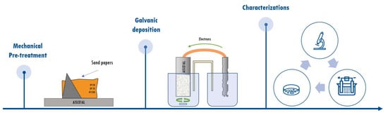
Scheme 1.
Workflow of the fabrication and characterization process.
3. Results and Discussion
Galvanic deposition was carried out in a two-compartment cell shown in Figure 1. Several reactions occurred once the working electrode and sacrificial anode were short-circuited and placed in their corresponding solutions.
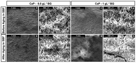
Figure 1.
Micrographs of the coatings: (a,b) CaP—0.5 gL−1 BG and (c,d) CaP—1 gL−1 BG post-deposition; (e,f) CaP—0.5 gL−1 BG; and (g,h) CaP—1 gL−1 BG after aging in simulated body fluid.
Zinc dissolution occurred in the anodic compart and has been represented in Equation (1):
Zn → Zn2+ + 2e− (E° = −0.76 V/NHE)
Regarding the cathodic compartment, base electrogeneration reactions [99,100] occurred thanks to the electrons stemming from Reaction (1). At the cathode, surface nitrate ions, water molecules, and dissolved oxygen react in the following reactions (Equations (2)–(4)):
NO3−+ H2O + 2e− →NO2− + 2OH− (Eeq = 0.0835 − 0.059 pH V/NHE)
2H2O + 2e− → 2OH− + H2 (Eeq = 0.0 − 0.059 pH V/NHE)
O2 + 2H2O +4e− →4OH− (Eeq = 1.23 − 0.059 pH V/NHE)
Due to the electrogeneration of hydroxyl ions, the deposition of calcium phosphate compounds is possible. The increase in the local pH at the cathode’s surface drives the mechanism of deposition, shifting the dissociation equilibrium of H2PO4− toward HPO42−, as shown in Equation (5):
H2PO4−+ OH− ↔ HPO42− + H2O (pH = 7.19)
Hydrogen phosphate ions formation induces the precipitation of brushite (CaHPO4·2H2O) according to Equation (6):
Ca2+ + HPO42− + 2H2O→ CaHPO4·2H2O
Since a non-uniform, non-conductive, and porous layer of brushite is formed, the reactions of base electrogeneration are not hindered. This ensures a continuous increase in the interface pH; therefore, the HPO42− ion dissociates in the PO43− ion according to equilibrium Equation (7):
HPO4 2− + OH− ↔ PO43− + H2O (pH = 12.03)
As soon as the pH reaches a value above 12, hydroxyapatite precipitation takes place, as shown in Equation (8):
10Ca2+ + 6PO43− + 2OH− → Ca10(PO4)6(OH)2 ↓ (pH > 12)
The composite coating is formed purely through physical incorporation during the deposition of calcium phosphates. The Bioglass present acts as a nucleation point for the formation of new crystals in the coating.
The mechanism of calcium phosphate formation in the presence of Bioglass has been extensively investigated in the literature [24]. In the first stage, there is ion exchange between H+ from the solution with the Na+ and Ca2+ from the Bioglass, which leads to the formation of silanol groups due to the hydrolysis of the silica groups. The reaction mechanism begins with the following reaction (Equation (9)):
Si-O-Ca2+ + H+ → Si-O-H + Ca2+
Afterward, the dissolution of silica leads to the formation of Si(OH)4 on the surface of the Bioglass, as shown in Equation (10):
Si-O-Si + H2O→2Si-OH
The dissolution of the lattice leads to the realization of an insoluble form of silica that will serve as a nucleation center for the formation of calcium phosphates. A silica gel layer with a thickness ranging from 1 to 2 μm is formed on the surface of the Bioglass particles. The precipitation and migration of calcium ions on the surface occur, followed by the incorporation of hydroxide anions and phosphates.
To obtain a composite coating, the Bioglass must be kept in suspension in the deposition solution. Therefore, a preliminary study was carried out to evaluate the effect of the stirring of the solution during the galvanic process. Stirring (shown in Figure S2 in the Supplementary Materials) leads to the formation of a calcium phosphate coating with a typical needle-like shape and a smaller crystal size compared with the product obtained under unstirred conditions. This effect was studied by Azar et al. [101], who observed the electro-crystallization of hydroxyapatite coatings on Nitinol while changing the fluid-dynamic conditions of the solution. The growth of hydroxyapatite crystals is a step that is favored over nucleation in unstirred conditions. A concentration gradient of the precursors is produced within the diffusive layer close to the electrode. Therefore, the ions involved are incorporated within the crystal lattice, and crystal growth occurs perpendicularly to the surface. Under stirred conditions, the diffusive layer is thinner, and the bulk concentration is almost the same as that at the electrode/electrolyte interface. So, in this case, crystal nucleation is favored with respect to growth. However, the precursor concentration is high enough to allow crystal growth parallel to the surface.
A comparison between the energy-dispersive X-ray spectra post-deposition and after aging is shown in Figure 2. These characterizations provide semi-qualitative information regarding the chemical composition of the coating. In particular, the atomic ratio Ca/P accounts for the composition of the coating. On the other hand, Ca/Fe provides semi-qualitative information about thickness.
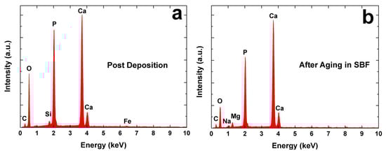
Figure 2.
Energy-dispersive X-ray spectra of calcium phosphate/Bioglass coating: (a) post-deposition and (b) after aging in simulated body fluid.
From the results reported in Table 1, it can be concluded that the thickness of the coating increased with the increase in the amount of Bioglass in the deposition solution. This is due to the Bioglass acting as a nucleation center for the formation of calcium phosphates. The results shown in Table 1 also demonstrate that the coatings are composed of a mixture of brushite (Ca/P = 1) and hydroxyapatite (Ca/P = 1.59~1.86). Although brushite could be the main crystalline phase, the Ca/P ratio increases to 1.66 after 21 days of aging in simulated body fluid.

Table 1.
Ca/P and Ca/Fe ratios, obtained using energy dispersive X-ray spectroscopy, of the coatings (post-deposition and after aging in simulated body fluid). The mean deviation is 1.2%.
This result can be explained by referring to Reaction (11) proposed by Nur et al. [102], which leads to the total conversion of the brushite in the hydroxyapatite during aging in simulated body fluid:
10CaHPO4 + 2OH− ↔ Ca10(PO4)6(OH)2 + 4PO43− + 10H+ (pH < 12)
Although Fe atoms could be detected after galvanic deposition, no Fe atoms were found after aging in simulated body fluid for 21 days. Thus, due to dissolution/reprecipitation phenomena, an increase in the thickness of the coating occurs with the aging time. The Si peak observed corresponds to the Bioglass particles incorporated in the coating.
It is interesting to notice how the Si peak is not identified after aging due to the bioactivity of Bioglass to produce hydroxyapatite. The absence of a Si peak is due to the coating’s dissolution in SBS. As reported in [103], the dissolution processes of composite coatings are quicker than pure calcium phosphate and Bioglass coatings. These high dissolution rates lead to rapid supersaturation at the coating/SBF interface and thus to the rapid precipitation of the hydroxyapatite phase [104]. Therefore, after immersion in SBF, the hydroxyapatite phase must be the only one present in the coating. To verify this phenomenon, the post-aged samples were characterized via XRD and Raman spectroscopy, and the results were compared with the pre-aged samples.
Figure 3 shows X-ray diffraction patterns of the samples’ varying Bioglass concentration. In Figure 3a, the characteristic brushite peaks were identified, with values of 2-theta equal to 11.65°, 20.95°, 29.3°, and 30.54°, as well as some hydroxyapatite peaks with lower intensity. In addition, some peaks belonging to the substrate were present. Nevertheless, the intensity of the peaks was shielded by the presence of the coating. No diffraction peaks could be detected for Bioglass due to its amorphous nature (see Figure S3 in the Supplementary Materials; the very broad band at about 32°–33° is typical of an amorphous structure).
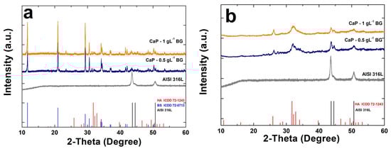
Figure 3.
X−ray diffraction patterns of calcium phosphate/Bioglass coatings: (a) before and (b) post-aging in simulated body fluid. The pattern of uncoated AISI 316L was also reported for comparison.
After 21 days of aging in simulated body fluid (Figure 3b), the brushite peaks disappeared, and hydroxyapatite peaks are the only ones present, which is a finding that is in line with the results of energy-dispersive X-ray spectroscopy.
Grain size was evaluated using Scherrer’s equation, considering the main peaks were located at around 2-theta 11.65° and 20.95°. The results (Figure S4 in the Supplementary Materials) demonstrate that the galvanic deposition of calcium phosphate in an unstirred solution leads to the formation of coatings with larger crystalline grain sizes. In a stirred solution, since the phenomenon of crystal nucleation is the predominant process compared to crystal growth, as reported earlier, a lower grain dimension was measured.
The addition of Bioglass in the solution causes a further decrease in the main grain sizes. This behavior is due to the incorporation of Bioglass in the calcium phosphate deposit, which continuously stimulates the formation of new nucleation sites and limits crystal growth [103]. The low crystallinity of the composite coating (which corresponds to a high level of reactivity and, therefore, a high dissolution/reprecipitation rate) is another reason for its high bioactivity in SBF [105]. Confirmation of these hypotheses was achieved using RAMAN spectroscopy. The spectra of the coatings following the deposition process (Figure 4a) show that the brushite modes were identified. In particular, the modes at 985 cm−1 and 878 cm−1 are related to the stretching (ν1 P-O) of the phosphate groups. The stretching (ν3 P-O) of the PO4 group was observed at 1081 cm−1 and 1059 cm−1. The bending of the HPO4 group (ν2 OPO) corresponds to the vibrational modes at 379 cm−1 and 415 cm−1. Furthermore, the stretching (ν3 P-O) of the HPO42− group was observed at 1121 cm−1 and is characterized by low intensity. Finally, the stretching (ν4 O-P-O: 530 cm−1) of the HPO42− group and the bending (ν4 P-O: 593 cm−1) of the PO4 group were observed. In addition, the typical hydroxyapatite stretching mode (ν1: 960 cm−1) was detected, although it had low intensity compared to the brushite main mode.
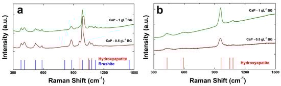
Figure 4.
RAMAN spectra of calcium phosphate/Bioglass coatings: (a) post-deposition and (b) post−aging in simulated body fluid.
As shown in Figure 4b, in both samples after aging, only the hydroxyapatite phase was detected, confirming the total conversion of brushite, which is in line with the results observed via energy-dispersive X-ray spectroscopy and X-ray diffraction.
Corrosion tests were carried out in simulated body fluid for 21 days to evaluate the performance of the coatings in terms of their resistance to corrosion phenomena. Figure S5 (in the Supplementary Materials) shows the open-circuit potential (for 30 min) in simulated body fluid. The potential remained almost constant, and no unexpected changes were found, which could, in this case, occur due to the solubilization/precipitation of calcium phosphate. In addition, the value of the open-circuit potential shifts to more noble values than that of bare steel due to increased corrosion resistance. The sample CaP/BG 0.5 gL−1 (Figure S5a) was characterized by a constant potential. In contrast, the largest changes were observed during the first few days of immersion. A decrease in open-circuit potential value is observed from day 14. This phenomenon is attributable to the phase change induced by the brushite/hydroxyapatite equilibrium. Despite this phenomenon, nobler open-circuit potential values were recorded compared to bare steel.
The sample CaP-BG 1 gL−1 (Figure S5b) shows a similar trend. There was a significant increase in open-circuit potential value after the first day of immersion; then, a lower variation was noted under the dynamic equilibrium of calcium phosphate. A maximum open-circuit potential value of 0.081 V was recorded on day 14. Compared with the previous sample, higher values were recorded. This behavior is due to the greater presence of Bioglass, leading to the formation of a thicker coating.
Tafel curves have been provided in Figure 5. The values of corrosion potential (Ecorr) and corrosion current density (icorr) were evaluated through the extrapolation of the Tafel curves and have been reported in Table 2. The samples were characterized by a higher value of Ecorr than bare steel. In agreement with the results regarding open-circuit potential monitoring, the potential changes after day 14 were due to the equilibrium established between calcium phosphate compounds. Regarding icorr, the values were lower than the uncoated substrate.
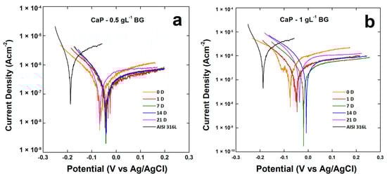
Figure 5.
Tafel plots of (a) CaP—0.5 gL−1 BG coating and (b) CaP—1 gL−1 BG coating during 21 days of aging in the simulated body fluid solution.
Table 2.
Ecorr and icorr of calcium phosphate/Bioglass coatings obtained by extrapolation of Tafel’s curves in Figure 5. For comparison, Ecorr and icorr of uncoated AISI 316L were also calculated. The mean standard deviation was ±1.7%.
The crystallinity of the coating can be related to its corrosion resistance. The CaP-BG 1gL−1 sample (with the smallest grain size and thus the lowest crystallinity) has the best Ecorr and icorr values due to the high coating dissolution/reprecipitation rate in simulated body fluid. The increased coating thickness and high reprecipitation rate due to the increased presence of Bioglass lead to the formation of a thicker deposit during aging, which results in better protective action against corrosive phenomena.
Electrochemical impedance spectroscopy measurements are reported in Figure 6. The best fitting was obtained using the equivalent circuit (Rs(CPE1(R1(CPE2(R2W))))) schematized in Figure S6 (presented in the Supplementary Materials). This equivalent circuit was proposed by Kathavate et al. [106] and simulated the behavior of inhomogeneous coatings modeled by Jüttner [107] to describe coatings with defects. In particular, the proposed model considers the presence of a porous coating in which diffusive processes occur. Rs represents the resistance of the simulated body fluid. CPE1 and R1 describe the behavior of the outer layer of the coating; alternatively, R2 corresponds to the pore resistance. CPE2 and R3 refer to the double-layer capacitance and charge transfer resistance, respectively. The Warburg element (W) was included to simulate diffusive processes within the porous structure. The CPE (Constant Phase Element) was used by Hinderliter [108] to model inhomogeneous coatings, the presence of defects, and composition variation.
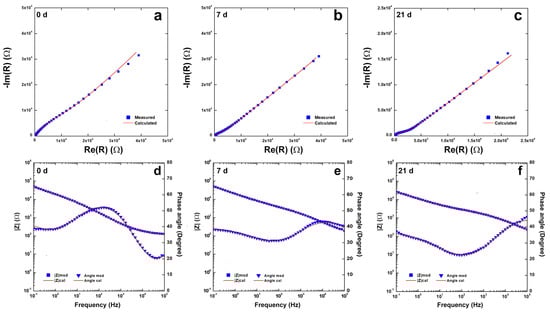
Figure 6.
Impedance spectra of calcium phosphate/Bioglass coating during 21 days of aging in simulated body fluid.
The obtained fitting (reported in Table S1) is characterized by a χ2 value of the magnitude of 10−4, and the relative error of each parameter is less than 10%. The evolution of the coating due to the equilibrium between brushite/hydroxyapatite was noted during aging. The values of the constant phase element exponents, n1 and n2, are lower than those of uncoated steel since the coating has a more complex morphology than a passive film on stainless steel. In any case, after 21 days, the overall impedance was higher than 104 Ω.
These results show that the galvanic method yields coatings with good corrosion resistance properties, which are better than those obtained through electrodeposition [109] and electrophoretic deposition [110]. However, it is worth noting that a direct comparison with other results is difficult to achieve. The performance of the coating is linked to its morphology, composition, and adhesion to the substrate, which strongly depend on the substrate itself, the deposition method, and the deposition conditions (i.e., temperature, agitation, and pH). However, we can compare these results with those concerning other coatings we obtained using the galvanic deposition method [82,84,86,87,88]. According to these results, it can be concluded that the composite with Bioglass has excellent performance, which is only surpassed by the composite with biopolymers such as chitosan and collagen.
Inductive plasma spectroscopy confirmed the ability of the coatings to limit corrosion phenomena. In particular, the concentration of metal ions (Fe, Ni, Cr, and Mo) released in the solution from the substrate after 21 days of aging in simulated body fluid was quantified. As can be observed in Table 3, the concentration of metal ions in the SBF used to age the samples is very low. In the case of iron, which is the most abundant element in steel, a concentration ten times lower than that of bare steel was found. A very low value was also detected in the case of nickel, which was well below the threshold limits for human health [111]. Furthermore, after 21 days, the concentration of Ca ions decreased in the simulated body fluid solution due to the incorporation of Ca ions within the calcium phosphate crystal structure [112] that occurs during aging. Contemporaneously, the number of P ions increased due to the equilibrium proposed by Nur et al. [102], wherein phosphate ions are released (Equation (11)).
Table 3.
Ion concentrations in the simulated body fluid solution after 3 weeks of aging. For comparison, the concentrations of Ca and P ions in the as-prepared simulated body fluid solution were reported (for both measured and calculated values). The mean standard deviation was 0.7%.
The biocompatibility of calcium phosphate/Bioglass-coated (CaP−1gL−1BG) or uncoated steel (AISI 316L) samples was investigated with respect to MC3T3-E1 pre-osteoblastic cells grown in a medium previously incubated with AISI 316L or CaP—1 gL−1 BG as reported in the Materials and Methods. Cells grown in a D-MEM medium were used as a control. The viability assay was performed after 2, 5, and 7 days of treatment using the CCK-8 assay. As reported in Figure 7, both samples (AISI 316L and CaP—1 gL−1 BG) presented viability values comparable to those of the control at each time point, suggesting the good biocompatibility of the devices. Therefore, the percentage of cell viability of AISI 316L and CaP—1 gL−1 BG (considering the untreated control cells’ percentage to be 100%) was more than 91% at each timepoint (reported in Table 4): after 2 days, 97.37% and 96.90%; after 5 days, 91.07% and 98.88%; and after 7 days, 91.82% and 92.26% for AISI 316L and CaP—1 gL−1 BG, respectively. The degree of cell viability, which was well over 70% compared to the control, confirms the non-cytotoxicity of the tested materials as determined by the ISO standard.
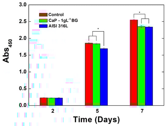
Figure 7.
Cell viability assay (CCK-8) of MC3T3-E1 cells grown for different times (2, 5, and 7 days) with complete D-MEM (red, positive control); the CaP—1 gL−1 BG (green) or AISI 316L D-MEM (blue). Viability was expressed as absorbance at 450 nm (Abs), which is directly proportional to cell viability. Error bars represent means ± SD for n = 10 (* p < 0.05).
Table 4.
Cell viability percentages normalized with respect to the control (100% viability).
These data were confirmed through an analysis of cell morphology (Figure 8), which showed an increase in cell density after 5 and 7 days at the same level as the control. Moreover, cell morphology observations showed discrete intra-cytoplasmatic granules, well-spread cells, and less than 20% round cells, indicating an absent or very low cytotoxic effect (less than 10%) and suggesting good biocompatibility. Therefore, these tests show that the calcium phosphate/Bioglass-coated samples are biocompatible and suitable for biomedical applications since they do not release cytotoxic products that alter cell growth.
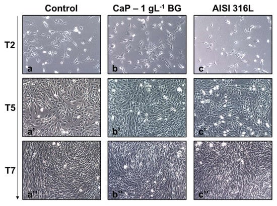
Figure 8.
Optical microscopy of MC3T3-E1 cells grown for different times (2, 5 (‘), and 7 (‘’) days) with: (a,a’,a’’) complete D-MEM (control); (b,b’,b’’) AISI 316L D-MEM; (c,c’,c’’) the CaP—1 gL−1 BG D-MEM. Magnificence 10X.
4. Conclusions
The galvanic deposition method was used to obtain composite coatings of calcium phosphate/Bioglass on AISI 316L. the coatings were achieved with different amounts of Bioglass 45S5, which was suspended in the deposition solution so that it could be incorporated during the deposition of the calcium phosphate compounds.
The obtained micrographs showed the formation of a uniform deposit characterized by small crystals, whose formation was probably due to the physical incorporation of Bioglass during deposition, which acts as nucleation points for new calcium phosphate crystals.
Through energy-dispersive X-ray spectroscopy, in addition to detecting the presence of Si originating from the Bioglass, the Ca/P ratio was calculated, and the values obtained were attributable to the deposition of both brushite and hydroxyapatite phases. The presence of these two phases was verified through both Raman spectroscopy and X-ray diffraction. Both techniques also revealed that the deposit mainly consists of brushite. Given its amorphous nature, no diffraction peaks of the Bioglass were detected. From the X-ray diffraction patterns and Scherrer’s equation, it was found that the presence of Bioglass in the bath leads to the formation of deposits with a smaller average grain size than deposits without Bioglass.
The coatings were aged for 21 days in simulated body fluid at 37 °C. After aging, the morphology of the deposit changed slightly, while its composition was completely different. Both Raman spectroscopy and X-ray diffraction showed the presence of only hydroxyapatite, and energy-dispersive X-ray spectroscopy also revealed the complete disappearance of Si. This behavior is typical of calcium phosphate compounds, which naturally tend to transform into hydroxyapatite when immersed in simulated body fluid. The disappearance of Si was also expected and is a confirmation of the Bioglass’s bioactivity, which, in simulated body fluid, further stimulates the dissolution of the coating and its reprecipitation in solely the hydroxyapatite phase.
Of great interest are the results of electrochemical characterization, which showed a nobler corrosion potential and lower corrosion current density for all samples compared to those of bare steel from the first day of aging in the simulated body fluid. The coating with the best performance in terms of resistance to corrosive phenomena was obtained with a concentration of Bioglass equal to 1 gL−1. Under these conditions, the coating with the lowest crystallinity and the highest thickness was obtained, which was characterized by a high dissolution/reprecipitation rate in simulated body fluid and thus better protective action against corrosive phenomena. The slowdown of corrosive phenomena in the presence of the coating was also confirmed through the inductive plasma spectroscopy analysis of the SBF used for aging. Lower concentrations of Fe (10 times lower) and Ni (more than half) were found in these solutions compared to that measured in the solution used to treat bare steel.
Finally, biological tests carried out with MCT3-E1 pre-osteoblastic cells revealed that the coated samples do not influence typical cellular growth and, consequently, can be considered non-cytotoxic and suitable for biomedical purposes. Further research is underway to evaluate the scalability of the method using areas much larger than those studied herein and deposition on nonplanar substrates to simulate the actual shape of a prosthesis. Experimentation is also underway using the Ti alloy (Ti-6Al-4V), which we are coating with a CaP-Polymer-Drug composite, again using the galvanic method.
Supplementary Materials
The following supporting information can be downloaded at: https://www.mdpi.com/article/10.3390/coatings13061006/s1, Figure S1: Cell layout; Figure S2: SEM images of CaP coatings obtained via galvanic deposition under different conditions: (a) unstirring (b) and stirring; Figure S3: XRD pattern of Bioglass 45S5 powder; Figure S4: Grain size calculated via Scherrer’s equation at 2-theta degree equal to 11.65 and 20.95; Figure S5: OCP curves of (a) CaP—BG 0.5 gL−1 and (b) CaP—BG 1 gL−1; Figure S6: Equivalent circuit used to fit EIS data; Table S1: Composition of SBF; Table S2: Fitting parameters of EIS data obtained for CaP—BG 1gL−1.
Author Contributions
Conceptualization, C.Z., A.M., B.P., F.L. and F.C.P.; methodology, C.Z., A.M., B.P., F.L., E.C., S.C. and F.C.P.; validation, C.Z., B.P., F.L., E.C., S.C. and F.C.P.; formal analysis, C.Z.; investigation, C.Z., A.M., B.P., F.L., E.C., S.C. and F.C.P.; data curation, C.Z.; writing—original draft preparation, C.Z., B.P., E.C., F.C.P. and R.I.; writing—review and editing, R.I., V.B., and V.L.C.; supervision, R.I., V.B. and V.L.C. All authors have read and agreed to the published version of the manuscript.
Funding
This research received no external funding.
Institutional Review Board Statement
Not applicable.
Informed Consent Statement
Not applicable.
Data Availability Statement
Not applicable.
Conflicts of Interest
The authors declare no conflict of interest.
References
- Carter, C.B.; Norton, M.G. Ceramic Materials: Science and Engineering; Springer Science+Business Media, LLC Springer e-books: New York, NY, USA, 2007. [Google Scholar]
- Pomeroy, M.; Cambier, F. (Eds.) Encyclopedia of Materials: Technical Ceramics and Glasses; Elsevier: Amsterdam, The Netherlands, 2021. [Google Scholar]
- Hojo, J. (Ed.) Materials Chemistry of Ceramics; Springer: Singapore, 2019. [Google Scholar]
- Huang, J.; Best, S. Ceramic biomaterials for tissue engineering. In Tissue Engineering Using Ceramics and Polymers; Elsevier: Amsterdam, The Netherlands, 2014; pp. 3–34. [Google Scholar] [CrossRef]
- Osaka, A.; Narayan, R. (Eds.) Bioceramics: From Macro to Nanoscale; Elsevier: Amsterdam, The Netherlands; Oxford, UK; Cambridge, MA, USA, 2021. [Google Scholar]
- Farid, S.B.H. Bioceramics: For Materials Science and Engineering; Elsevier/Woodhead Publishing: Duxford, UK; Cambridge, MA, USA, 2019. [Google Scholar]
- Ravaglioli, A.; Krajewski, A. Bioceramics; Springer: Dordrecht, The Netherlands, 1992. [Google Scholar] [CrossRef]
- Abbas, Z.; Dapporto, M.; Tampieri, A.; Sprio, S. Toughening of Bioceramic Composites for Bone Regeneration. J. Compos. Sci. 2021, 5, 259. [Google Scholar] [CrossRef]
- Wang, K.; Zhou, C.; Hong, Y.; Zhang, X. A review of protein adsorption on bioceramics. Interface Focus. 2012, 2, 259–277. [Google Scholar] [CrossRef] [PubMed]
- Pawelec, K.M.; Planell, J.A. (Eds.) Bone Repair Biomaterials: Regeneration and Clinical Applications, 2nd ed.; Elsevier/Woodhead Publishing: Duxford, UK; Cambridge, MA, USA, 2019. [Google Scholar]
- Mistry, S.; Kundu, D.; Datta, S.; Basu, D. Comparison of bioactive glass coated and hydroxyapatite coated titanium dental implants in the human jaw bone: Comparison of bioactive glass coated and hydroxyapatite coated implants. Aust. Dent. J. 2011, 56, 68–75. [Google Scholar] [CrossRef] [PubMed]
- Ammarullah, M.; Santoso, G.; Sugiharto, S.; Supriyono, T.; Wibowo, D.; Kurdi, O.; Tauviqirrahman, M.; Jamari, J. Minimizing Risk of Failure from Ceramic-on-Ceramic Total Hip Prosthesis by Selecting Ceramic Materials Based on Tresca Stress. Sustainability 2022, 14, 13413. [Google Scholar] [CrossRef]
- Buj-Corral, I.; Tejo-Otero, A. 3D Printing of Bioinert Oxide Ceramics for Medical Applications. J. Funct. Biomater. 2022, 13, 155. [Google Scholar] [CrossRef]
- Piconi, C. Bioinert Ceramics: State-of-the-Art. Key Eng. Mater. 2017, 758, 3–13. [Google Scholar] [CrossRef]
- Hench, L.L. Bioactive Ceramics: Theory and Clinical Applications. In Bioceramics; Elsevier: Amsterdam, The Netherlands, 1994; pp. 3–14. [Google Scholar]
- Ohtsuki, C.; Kamitakahara, M.; Miyazaki, T. Bioactive ceramic-based materials with designed reactivity for bone tissue regeneration. J. R. Soc. Interface. 2009, 6, S349–S360. [Google Scholar] [CrossRef]
- Salinas, A.J.; Vallet-Regí, M. Bioactive ceramics: From bone grafts to tissue engineering. RSC Adv. 2013, 3, 11116. [Google Scholar] [CrossRef]
- Poitout, D.G. (Ed.) Biomechanics and Biomaterials in Orthopedics, 2nd ed.; Springer: London, UK, 2016. [Google Scholar] [CrossRef]
- Bohner, M. Bioresorbable ceramics. In Degradation Rate of Bioresorbable Materials; Elsevier: Amsterdam, The Netherlands, 2008; pp. 95–114. [Google Scholar] [CrossRef]
- Dehghanghadikolaei, A.; Fotovvati, B. Coating Techniques for Functional Enhancement of Metal Implants for Bone Replacement: A Review. Materials 2019, 12, 1795. [Google Scholar] [CrossRef]
- Harun, W.S.W.; Asri, R.I.M.; Alias, J.; Zulkifli, F.H.; Kadirgama, K.; Ghani, S.A.C.; Shariffuddin, J.H.M. A comprehensive review of hydroxyapatite-based coatings adhesion on metallic biomaterials. Ceram. Int. 2018, 44, 1250–1268. [Google Scholar] [CrossRef]
- Skallevold, H.E.; Rokaya, D.; Khurshid, Z.; Zafar, M.S. Bioactive Glass Applications in Dentistry. Int. J. Mol. Sci. 2019, 20, 5960. [Google Scholar] [CrossRef]
- Ylänen, H.O. (Ed.) Bioactive Glasses: Materials, Properties and Applications, 2nd ed.; Elsevier/Woodhead Publishing: Duxford, UK, 2018. [Google Scholar]
- Karadjian, M.; Essers, C.; Tsitlakidis, S.; Reible, B.; Moghaddam, A.; Boccaccini, A.; Westhauser, F. Biological Properties of Calcium Phosphate Bioactive Glass Composite Bone Substitutes: Current Experimental Evidence. Int. J. Mol. Sci. 2019, 20, 305. [Google Scholar] [CrossRef]
- Kaur, G. Bioactive Glasses: Potential Biomaterials for Future Therapy, 1st ed.; Springer International Publishing: Cham, Swizerland, 2017. [Google Scholar] [CrossRef]
- Varila, L.; Fagerlund, S.; Lehtonen, T.; Tuominen, J.; Hupa, L. Surface reactions of bioactive glasses in buffered solutions. J. Eur. Ceram. Soc. 2012, 32, 2757–2763. [Google Scholar] [CrossRef]
- Fernandes, H.R.; Gaddam, A.; Rebelo, A.; Brazete, D.; Stan, G.E.; Ferreira, J.M.F. Bioactive Glasses and Glass-Ceramics for Healthcare Applications in Bone Regeneration and Tissue Engineering. Materials 2018, 11, 2530. [Google Scholar] [CrossRef]
- Drago, L.; Toscano, M.; Bottagisio, M. Recent Evidence on Bioactive Glass Antimicrobial and Antibiofilm Activity: A Mini-Review. Materials 2018, 11, 326. [Google Scholar] [CrossRef]
- Hench, L.L.; Jones, J.R. Bioactive Glasses: Frontiers and Challenges. Front. Bioeng. Biotechnol. 2015, 3, 194. [Google Scholar] [CrossRef]
- Baino, F.; Hamzehlou, S.; Kargozar, S. Bioactive Glasses: Where Are We and Where Are We Going? J. Funct. Biomater. 2018, 9, 25. [Google Scholar] [CrossRef]
- Fiume, E.; Barberi, J.; Verné, E.; Baino, F. Bioactive Glasses: From Parent 45S5 Composition to Scaffold-Assisted Tissue-Healing Therapies. J. Funct. Biomater. 2018, 9, 24. [Google Scholar] [CrossRef]
- Baino, F.; Verné, E. Glass-based coatings on biomedical implants: A state-of-the-art review. Biomed. Glas. 2017, 3, 1–17. [Google Scholar] [CrossRef]
- Oliver, J.N.; Su, Y.; Lu, X.; Kuo, P.-H.; Du, J.; Zhu, D. Bioactive glass coatings on metallic implants for biomedical applications. Bioact. Mater. 2019, 4, 261–270. [Google Scholar] [CrossRef]
- Camponogara, F.; Zanotti, F.; Trentini, M.; Tiengo, E.; Zanolla, I.; Pishavar, E.; Soliani, E.; Scatto, M.; Gargiulo, P.; Zambito, Y.; et al. Biomaterials for Regenerative Medicine in Italy: Brief State of the Art of the Principal Research Centers. Int. J. Mol. Sci. 2022, 23, 8245. [Google Scholar] [CrossRef] [PubMed]
- Vaez, S.; Emadi, R.; Sadeghzade, S.; Salimijazi, H.; Kharaziha, M. Electrophoretic deposition of chitosan reinforced baghdadite ceramic nano-particles on the stainless steel 316L substrate to improve biological and physical characteristics. Mater. Chem. Phys. 2022, 282, 125991. [Google Scholar] [CrossRef]
- Smith, J.R.; Lamprou, D.A.; Larson, C.; Upson, S.J. Biomedical applications of polymer and ceramic coatings: A review of recent developments. Trans. IMF 2022, 100, 25–35. [Google Scholar] [CrossRef]
- Wang, Y.; Wu, B.; Ai, S.; Wan, D. Electroplating of HAp-brushite coating on metallic bioimplants with advanced hemocompatibility and osteocompatibility properties. J. Appl. Biomater. Funct. Mater. 2022, 20, 228080002211039. [Google Scholar] [CrossRef]
- Jiménez-García, F.N.; Giraldo-Torres, L.R.; Restrepo-Parra, E. Electrochemically Deposited Calcium Phosphate Coatings Using a Potentiostat of In-house Design and Implementation. Mat. Res. 2021, 24, e20210098. [Google Scholar] [CrossRef]
- Ghiasi, B.; Sefidbakht, Y.; Rezaei, M. Hydroxyapatite for Biomedicine and Drug Delivery. In Nanomaterials for Advanced Biological Applications; Rahmandoust, M., Ayatollahi, M.R., Eds.; Springer International Publishing: Cham, Swizerland, 2019; Volume 104, pp. 85–120. [Google Scholar] [CrossRef]
- LeGeros, R.Z. Properties of Osteoconductive Biomaterials: Calcium Phosphates. Clin. Orthop. Relat. Res. 2002, 395, 81–98. [Google Scholar] [CrossRef]
- Eliaz, N.; Metoki, N. Calcium Phosphate Bioceramics: A Review of Their History, Structure, Properties, Coating Technologies and Biomedical Applications. Materials 2017, 10, 334. [Google Scholar] [CrossRef]
- Hou, X.; Zhang, L.; Zhou, Z.; Luo, X.; Wang, T.; Zhao, X.; Lu, B.; Chen, F.; Zheng, L. Calcium Phosphate-Based Biomaterials for Bone Repair. J. Funct. Biomater. 2022, 13, 187. [Google Scholar] [CrossRef]
- Ielo, I.; Calabrese, G.; De Luca, G.; Conoci, S. Recent Advances in Hydroxyapatite-Based Biocomposites for Bone Tissue Regeneration in Orthopedics. Int. J. Mol. Sci. 2022, 23, 9721. [Google Scholar] [CrossRef]
- Shi, H.; Zhou, Z.; Li, W.; Fan, Y.; Li, Z.; Wei, J. Hydroxyapatite Based Materials for Bone Tissue Engineering: A Brief and Comprehensive Introduction. Crystals 2021, 11, 149. [Google Scholar] [CrossRef]
- Layrolle, P.; Daculsi, G. Physicochemistry of Apatite and Its Related Calcium Phosphates. In Thin Calcium Phosphate Coatings for Medical Implants; León, B., Jansen, J., Eds.; Springer: New York, NY, USA, 2009; pp. 19–21. [Google Scholar] [CrossRef]
- Dutta, S.R.; Passi, D.; Singh, P.; Bhuibhar, A. Ceramic and non-ceramic hydroxyapatite as a bone graft material: A brief review. Ir. J. Med. Sci. 2015, 184, 101–106. [Google Scholar] [CrossRef]
- Awasthi, S.; Pandey, S.K.; Arunan, E.; Srivastava, C. A review on hydroxyapatite coatings for the biomedical applications: Experimental and theoretical perspectives. J. Mater. Chem. B 2021, 9, 228–249. [Google Scholar] [CrossRef]
- El Hadad, A.; Peón, E.; García-Galván, F.; Barranco, V.; Parra, J.; Jiménez-Morales, A.; Galván, J. Biocompatibility and Corrosion Protection Behaviour of Hydroxyapatite Sol-Gel-Derived Coatings on Ti6Al4V Alloy. Materials 2017, 10, 94. [Google Scholar] [CrossRef]
- Grebņevs, V.; Leśniak-Ziółkowska, K.; Wala, M.; Dulski, M.; Altundal, Ş.; Dutovs, A.; Avotiņa, L.; Erts, D.; Viter, R.; Vīksna, A.; et al. Modification of physicochemical properties and bioactivity of oxide coatings formed on Ti substrates via plasma electrolytic oxidation in crystalline and amorphous calcium phosphate particle suspensions. Appl. Surf. Sci. 2022, 598, 153793. [Google Scholar] [CrossRef]
- Zhang, G.; Xu, Y.; Zeng, Z.; Cao, B. Enhanced the corrosion resistance and biocompatibility of magnesium alloy by hydroxyapatite composite coating of AZ31/Ti/PDA/HA. Surf. Topogr. Metrol. Prop. 2021, 9, 025042. [Google Scholar] [CrossRef]
- Predoi, D.; Iconaru, S.L.; Ciobanu, S.C.; Predoi, S.-A.; Buton, N.; Megier, C.; Beuran, M. Development of Iron-Doped Hydroxyapatite Coatings. Coatings 2021, 11, 186. [Google Scholar] [CrossRef]
- Predoi, D.; Ciobanu, S.C.; Iconaru, S.L.; Predoi, M.V. Influence of the Biological Medium on the Properties of Magnesium Doped Hydroxyapatite Composite Coatings. Coatings 2023, 13, 409. [Google Scholar] [CrossRef]
- Ciobanu, C.S.; Predoi, M.V.; Buton, N.; Megier, C.; Iconaru, S.L.; Predoi, D. Physicochemical Characterization of Europium-Doped Hydroxyapatite Thin Films with Antifungal Activity. Coatings 2022, 12, 306. [Google Scholar] [CrossRef]
- Iconaru, S.L.; Groza, A.; Gaiaschi, S.; Rokosz, K.; Raaen, S.; Ciobanu, S.C.; Chapon, P.; Predoi, D. Antimicrobial Properties of Samarium Doped Hydroxyapatite Suspensions and Coatings. Coatings 2020, 10, 1124. [Google Scholar] [CrossRef]
- Iconaru, S.L.; Predoi, D.; Ciobanu, C.S.; Motelica-Heino, M.; Guegan, R.; Bleotu, C. Development of Silver Doped Hydroxyapatite Thin Films for Biomedical Applications. Coatings 2022, 12, 341. [Google Scholar] [CrossRef]
- Predoi, D.; Iconaru, S.L.; Predoi, M.V.; Groza, A.; Gaiaschi, S.; Rokosz, K.; Raaen, S.; Negrila, C.C.; Prodan, A.-M.; Costescu, A.; et al. Development of Cerium-Doped Hydroxyapatite Coatings with Antimicrobial Properties for Biomedical Applications. Coatings 2020, 10, 516. [Google Scholar] [CrossRef]
- Filip, D.G.; Surdu, V.-A.; Paduraru, A.V.; Andronescu, E. Current Development in Biomaterials—Hydroxyapatite and Bioglass for Applications in Biomedical Field: A Review. J. Funct. Biomater. 2022, 13, 248. [Google Scholar] [CrossRef] [PubMed]
- Ryu, J.-H.; Kwon, J.-S.; Kim, K.-M.; Hong, H.J.; Koh, W.-G.; Lee, J.; Lee, H.-J.; Choi, H.-J.; Yi, S.; Shin, H.; et al. Synergistic Effect of Porous Hydroxyapatite Scaffolds Combined with Bioactive Glass/Poly(lactic-co-glycolic acid) Composite Fibers Promotes Osteogenic Activity and Bioactivity. ACS Omega 2019, 4, 2302–2310. [Google Scholar] [CrossRef]
- Ebrahimi, S.; Hanim, Y.U.; Sipaut, C.S.; Jan, N.B.A.; Arshad, S.E.; How, S.E. Fabrication of Hydroxyapatite with Bioglass Nanocomposite for Human Wharton’s-Jelly-Derived Mesenchymal Stem Cell Growing Substrate. Int. J. Mol. Sci. 2021, 22, 9637. [Google Scholar] [CrossRef]
- Mesquita-Guimarães, J.; Detsch, R.; Souza, A.C.; Henriques, B.; Silva, F.S.; Boccaccini, A.R.; Carvalho, O. Cell adhesion evaluation of laser-sintered HAp and 45S5 bioactive glass coatings on micro-textured zirconia surfaces using MC3T3-E1 osteoblast-like cells. Mater. Sci. Eng. C 2020, 109, 110492. [Google Scholar] [CrossRef]
- Hong, Z.; Mello, A.; Yoshida, T.; Luan, L.; Stern, P.H.; Rossi, A.; Ellis, D.E.; Ketterson, J.B. Osteoblast proliferation on hydroxyapatite coated substrates prepared by right angle magnetron sputtering. J. Biomed. Mater. Res. 2010, 93, 878–885. [Google Scholar] [CrossRef]
- Maximov, M.; Maximov, O.-C.; Craciun, L.; Ficai, D.; Ficai, A.; Andronescu, E. Bioactive Glass—An Extensive Study of the Preparation and Coating Methods. Coatings 2021, 11, 1386. [Google Scholar] [CrossRef]
- Gomez-Vega, J.M.; Saiz, E.; Tomsia, A.P.; Marshall, G.W.; Marshall, S.J. Bioactive glass coatings with hydroxyapatite and Bioglass® particles on Ti-based implants. 1. Processing. Biomaterials 2000, 21, 105–111. [Google Scholar] [CrossRef]
- Cañas, E.; Orts, M.J.; Boccaccini, A.R.; Sánchez, E. Microstructural and in vitro characterization of 45S5 bioactive glass coatings deposited by solution precursor plasma spraying (SPPS). Surf. Coat. Technol. 2019, 371, 151–160. [Google Scholar] [CrossRef]
- Mahato, A.; De, M.; Bhattacharjee, P.; Kumar, V.; Mukherjee, P.; Singh, G.; Kundu, B.; Balla, V.K.; Nandi, S.K. Role of calcium phosphate and bioactive glass coating on in vivo bone healing of new Mg–Zn–Ca implant. J. Mater. Sci. Mater. Med. 2021, 32, 55. [Google Scholar] [CrossRef]
- Cattini, A.; Bellucci, D.; Sola, A.; Pawłowski, L.; Cannillo, V. Microstructural design of functionally graded coatings composed of suspension plasma sprayed hydroxyapatite and bioactive glass: Microstructural Design Of Functionally Graded Coatings. J. Biomed. Mater. Res. 2014, 102, 551–560. [Google Scholar] [CrossRef]
- Berbecaru, C.; Alexandru, H.V.; Stan, G.E.; Marcov, D.A.; Pasuk, I.; Ianculescu, A. First stages of bioactivity of glass-ceramics thin films prepared by magnetron sputtering technique. Mater. Sci. Eng. B 2010, 169, 101–105. [Google Scholar] [CrossRef]
- Dhinasekaran, D.; Kaliaraj, G.S.; Jagannathan, M.; Rajendran, A.R.; Prakasarao, A.; Ganesan, S.; Subramanian, B. Pulsed laser deposition of nanostructured bioactive glass and hydroxyapatite coatings: Microstructural and electrochemical characterization. Mater. Sci. Eng. C 2021, 130, 112459. [Google Scholar] [CrossRef]
- Garrido, B.; Dosta, S.; Cano, I.G. Bioactive glass coatings obtained by thermal spray: Current status and future challenges. BoletÍN Soc. Española CerÁMica Vidr. 2022, 61, 516–530. [Google Scholar] [CrossRef]
- Comesaña, R.; del Val, J.; Quintero, F.; Riveiro, A.; Arias-González, F.; Boutinguiza, M.; Lusquiños, F.; Pou, J. Laser Cladding and Laser Direct Glass Deposition of Bioactive Glass and Glass-Ceramics. In Bioactive Glasses and Glass-Ceramics; Baino, F., Kargozar, S., Eds.; Wiley: Hoboken, NJ, USA, 2022; pp. 311–340. [Google Scholar] [CrossRef]
- Khanmohammadi, S.; Ojaghi-Ilkhchi, M.; Farrokhi-Rad, M. Evaluation of bioglass and hydroxyapatite based nanocomposite coatings obtained by electrophoretic deposition. Ceram. Int. 2020, 46, 26069–26077. [Google Scholar] [CrossRef]
- Safavi, M.S.; Walsh, F.C.; Surmeneva, M.A.; Surmenev, R.A.; Khalil-Allafi, J. Electrodeposited Hydroxyapatite-Based Biocoatings: Recent Progress and Future Challenges. Coatings 2021, 11, 110. [Google Scholar] [CrossRef]
- Taranu, B.-O.; Ianasi, P.; Rus, S.F.; Bucur, A.I. Simultaneous Precipitation and Electrodeposition of Hydroxyapatite Coatings at Different Temperatures on Various Metal Substrates. Coatings 2022, 12, 288. [Google Scholar] [CrossRef]
- Say, Y.; Aksakal, B. Enhanced corrosion properties of biological NiTi alloy by hydroxyapatite and bioglass based biocomposite coatings. J. Mater. Res. Technol. 2020, 9, 1742–1749. [Google Scholar] [CrossRef]
- Jaafar, A.; Hecker, C.; Árki, P.; Joseph, Y. Sol-Gel Derived Hydroxyapatite Coatings for Titanium Implants: A Review. Bioengineering 2020, 7, 127. [Google Scholar] [CrossRef]
- Azzouz, I.; Faure, J.; Khlifi, K.; Cheikh Larbi, A.; Benhayoune, H. Electrophoretic Deposition of 45S5 Bioglass® Coatings on the Ti6Al4V Prosthetic Alloy with Improved Mechanical Properties. Coatings 2020, 10, 1192. [Google Scholar] [CrossRef]
- Jamari, J.; Ammarullah, M.I.; Santoso, G.; Sugiharto, S.; Supriyono, T.; van der Heide, E. In Silico Contact Pressure of Metal-on-Metal Total Hip Implant with Different Materials Subjected to Gait Loading. Metals 2022, 12, 1241. [Google Scholar] [CrossRef]
- Fan, X.; Chen, J.; Zou, J.; Wan, Q.; Zhou, Z.; Ruan, J. Bone-like apatite formation on HA/316L stainless steel composite surface in simulated body fluid. Trans. Nonferrous Met. Soc. China 2009, 19, 347–352. [Google Scholar] [CrossRef]
- Beig, B.; Liaqat, U.; Niazi, M.F.K.; Douna, I.; Zahoor, M.; Niazi, M.B.K. Current Challenges and Innovative Developments in Hydroxyapatite-Based Coatings on Metallic Materials for Bone Implantation: A Review. Coatings 2020, 10, 1249. [Google Scholar] [CrossRef]
- Schlesinger, M.; Paunovic, M. (Eds.) Modern Electroplating, 5th ed.; Wiley: Hoboken, NJ, USA, 2010. [Google Scholar]
- Zanca, C.; Cordaro, G.; Capuana, E.; Brucato, V.; Pavia, F.C.; Carrubba, V.L.; Ghersi, G.; Inguanta, R. Galvanic Deposition Of Hydroxyapatite/Chitosan/Collagen Coatings On 304 Stainless Steel. Chem. Eng. Trans. 2021, 86, 6. [Google Scholar] [CrossRef]
- Mendolia, I.; Zanca, C.; Ganci, F.; Conoscenti, G.; Pavia, F.C.; Brucato, V.; La Carrubba, V.; Lopresti, F.; Piazza, S.; Sunseri, C.; et al. Calcium phosphate/polyvinyl acetate coatings on SS304 via galvanic co-deposition for orthopedic implant applications. Surf. Coat. Technol. 2021, 408, 126771. [Google Scholar] [CrossRef]
- Zanca, C.; Mendolia, I.; Capuana, E.; Blanda, G.; Carfì Pavia, F.; Brucato, V.; Ghersi, G.; la Carrubba, V.; Piazza, S.; Sunseri, C.; et al. Co-Deposition and Characterization of Hydroxyapatite-Chitosan and Hydroxyapatite-Polyvinylacetate Coatings on 304 SS for Biomedical Devices. KEM 2019, 813, 153–158. [Google Scholar] [CrossRef]
- Zanca, C.; Patella, B.; Capuana, E.; Lopresti, F.; Brucato, V.; Carfì Pavia, F.; La Carrubba, V.; Inguanta, R. Behavior of Calcium Phosphate–Chitosan–Collagen Composite Coating on AISI 304 for Orthopedic Applications. Polymers 2022, 14, 5108. [Google Scholar] [CrossRef]
- Zanca, C.; Carbone, S.; Patella, B.; Lopresti, F.; Aiello, G.; Brucato, V.; Carfì Pavia, F.; La Carrubba, V.; Inguanta, R. Composite Coatings of Chitosan and Silver Nanoparticles Obtained by Galvanic Deposition for Orthopedic Implants. Polymers 2022, 14, 3915. [Google Scholar] [CrossRef]
- Blanda, G.; Brucato, V.; Pavia, F.C.; Greco, S.; Piazza, S.; Sunseri, C.; Inguanta, R. In Vitro Corrosion and Biocompatibility of Brushite/Hydroxyapatite Coatings Obtained by Galvanic Deposition on 316LSS. J. Electrochem. Soc. 2018, 165, G1–G10. [Google Scholar] [CrossRef]
- Blanda, G.; Brucato, V.; Carfì, F.; Conoscenti, G.; La Carrubba, V.; Piazza, S.; Sunseri, C.; Inguanta, R. Chitosan-Coating Deposition via Galvanic Coupling. ACS Biomater. Sci. Eng. 2019, 5, 1715–1724. [Google Scholar] [CrossRef]
- Blanda, G.; Brucato, V.; Pavia, F.C.; Greco, S.; Piazza, S.; Sunseri, C.; Inguanta, R. Galvanic deposition and characterization of brushite/hydroxyapatite coatings on 316L stainless steel. Mater. Sci. Eng. C 2016, 64, 93–101. [Google Scholar] [CrossRef]
- Chen, B.; Liang, C. Preparation of hydroxyapatite coating by the use of a sacrificial Mg anode method. Ceram. Int. 2007, 33, 701–703. [Google Scholar] [CrossRef]
- Inguanta, R.; Ferrara, G.; Piazza, S.; Sunseri, C. A new route to grow oxide nanostructures based on metal displacement deposition. Lanthanides oxy/hydroxides growth. Electrochim. Acta 2012, 76, 77–87. [Google Scholar] [CrossRef]
- Inguanta, R.; Piazza, S.; Sunseri, C. A Route to Grow Oxide Nanostructures Based on Metal Displacement Deposition: Lanthanides Oxy/Hydroxides Characterization. J. Electrochem. Soc. 2012, 159, D493–D500. [Google Scholar] [CrossRef]
- Battaglia, M.; Piazza, S.; Sunseri, C.; Inguanta, R. Amorphous silicon nanotubes via galvanic displacement deposition. Electrochem. Commun. 2013, 34, 134–137. [Google Scholar] [CrossRef]
- Patella, B.; Russo, R.R.; Aiello, G.; Sunseri, C.; Inguanta, R. Vertical standing copper nanowires for electrochemical sensor of nitrate in water. In Proceedings of the 2020 IEEE International Conference on Flexible and Printable Sensors and Systems (FLEPS), Manchester, UK, 16–19 August 2020; pp. 1–4. [Google Scholar] [CrossRef]
- Inguanta, R.; Ferrara, G.; Piazza, S.; Sunseri, C. Fabrication and characterization of metal and metal oxide nanostructures grown by metal displacement deposition into anodic alumina membranes. Chem. Eng. Trans. 2011, 24, 199–204. [Google Scholar] [CrossRef]
- Papaderakis, A.; Mintsouli, I.; Georgieva, J.; Sotiropoulos, S. Electrocatalysts Prepared by Galvanic Replacement. Catalysts 2017, 7, 80. [Google Scholar] [CrossRef]
- Available online: https://www.legor.com/en-us/introduction-the-galvanic-process (accessed on 1 January 2020).
- Power Diffraction File; International Centre for Diffraction Data: Newtown Square, PA, USA, 2007.
- Downs, R.T.; Hall-Wallace, M. The American Mineralogist Crystal Structure Database. Am. Mineral. 2003, 88, 247–250. [Google Scholar]
- Therese, G.H.A.; Kamath, P.V. Cathodic reduction of different metal salt solutions Part I: Synthesis of metal hydroxides by electrogeneration of base. J. Appl. Electrochem. 1998, 28, 539–543. [Google Scholar] [CrossRef]
- Nobial, M.; Devos, O.; Mattos, O.R.; Tribollet, B. The nitrate reduction process: A way for increasing interfacial pH. J. Electroanal. Chem. 2007, 600, 87–94. [Google Scholar] [CrossRef]
- Azar, Z.; Khalil-Allafi, J.; Etminanfar, M.R. Electro-crystallization of hydroxyapatite coatings on Nitinol rotating disk electrode. Mater. Res. Express 2019, 6, 055401. [Google Scholar] [CrossRef]
- Nur, A.; Setyawan, H.; Widjaja, A.; Lenggoro, I.W. Electrochemical Processes for the Formation of Hydroxyapatite Powders. Bull. Chem. React. Eng. Catal. 2014, 9, 168–174. [Google Scholar] [CrossRef]
- Ebrahimi, S.; Sipaut, C.S. Synthesis of Hydroxyapatite/Bioglass Composite Nanopowder Using Design of Experiments. Nanomaterials 2022, 12, 2264. [Google Scholar] [CrossRef] [PubMed]
- Botelho, C.M.; Lopes, M.A.; Gibson, I.R.; Best, S.M.; Santos, J.D. Structural analysis of Si-substituted hydroxyapatite: Zeta potential and X-ray photoelectron spectroscopy. J. Mater. Sci. Mater. Med. 2002, 13, 1123–1127. [Google Scholar] [CrossRef] [PubMed]
- Aminian, A.; Solati-Hashjin, M.; Samadikuchaksaraei, A.; Bakhshi, F.; Gorjipour, F.; Farzadi, A.; Moztarzadeh, F.; Schmücker, M. Synthesis of silicon-substituted hydroxyapatite by a hydrothermal method with two different phosphorous sources. Ceram. Int. 2011, 37, 1219–1229. [Google Scholar] [CrossRef]
- Kathavate, V.S.; Pawar, D.N.; Bagal, N.S.; Deshpande, P.P. Role of nano ZnO particles in the electrodeposition and growth mechanism of phosphate coatings for enhancing the anti-corrosive performance of low carbon steel in 3.5% NaCl aqueous solution. J. Alloys Compd. 2020, 823, 153812. [Google Scholar] [CrossRef]
- Jüttner, K. Electrochemical impedance spectroscopy (EIS) of corrosion processes on inhomogeneous surfaces. Electrochim. Acta 1990, 35, 1501–1508. [Google Scholar] [CrossRef]
- Hinderliter, B.R.; Croll, S.G.; Tallman, D.E.; Su, Q.; Bierwagen, G.P. Interpretation of EIS data from accelerated exposure of coated metals based on modeling of coating physical properties. Electrochim. Acta 2006, 51, 4505–4515. [Google Scholar] [CrossRef]
- Thanh, D.T.M.; Nam, P.T.; Phuong, N.T.; Que, L.X.; Anh, N.V.; Hoang, T.; Lam, T.D. Controlling the electrodeposition, morphology and structure of hydroxyapatite coating on 316L stainless steel. Mater. Sci. Eng. C 2013, 33, 2037–2045. [Google Scholar] [CrossRef]
- Yazdani Samani, F.; Rabiee, S.M.; Jamaati, R.; Bagherifard, S. Effect of shot peening on electrophoretic deposition of bioactive glass coating on AISI 316L stainless steel. Ceram. Int. 2023, 49, 17468–17478. [Google Scholar] [CrossRef]
- Leikin, J.B.; Paloucek, F.P. (Eds.) Poisoning and Toxicology Handbook, 4th ed.; CRC Press/Taylor & Francis Group: Boca Raton, FL, USA, 2008. [Google Scholar]
- Shibata, H.; Yokoi, T.; Goto, T.; Kim, I.Y.; Kawashita, M.; Kikuta, K.; Ohtsuki, C. Behavior of hydroxyapatite crystals in a simulated body fluid: Effects of crystal face. J. Ceram. Soc. Jpn. 2013, 121, 807–812. [Google Scholar] [CrossRef]


Disclaimer/Publisher’s Note: The statements, opinions and data contained in all publications are solely those of the individual author(s) and contributor(s) and not of MDPI and/or the editor(s). MDPI and/or the editor(s) disclaim responsibility for any injury to people or property resulting from any ideas, methods, instructions or products referred to in the content. |
© 2023 by the authors. Licensee MDPI, Basel, Switzerland. This article is an open access article distributed under the terms and conditions of the Creative Commons Attribution (CC BY) license (https://creativecommons.org/licenses/by/4.0/).