Article

Influence of Silver-Coated Tool Electrode on Electrochemical Micromachining of Incoloy 825

by
Geethapriyan Thangamani
1,
Muthuramalingam Thangaraj
2,*,
Palani Iyamperumal Anand
1,
Mani Jayakumar
3,
Nikolaos E. Karkalos
4,*,
Emmanouil L. Papazoglou
4 and
Panagiotis Karmiris-Obratański
5,*
1
Mechatronics and Instrumentation Laboratory, Department of Mechanical Engineering, Indian Institute of Technology Indore, Khandwa Road, Simrol, Indore 453552, India
2
Department of Mechatronics Engineering, College of Engineering and Technology, SRM Institute of Science and Technology, Kattankulathur 603203, India
3
Electroplating and Metal Finishing Division, CSIR Central Electrochemical Research Institute (CSIR CECRI), Karaikudi 630006, India
4
Laboratory of Manufacturing Technology, School of Mechanical Engineering, National Technical University of Athens, 15780 Athens, Greece
5
Department of Manufacturing Systems, Faculty of Mechanical Engineering and Robotics, AGH University of Science and Technology, 30-059 Cracow, Poland
*
Authors to whom correspondence should be addressed.
Coatings 2023, 13(5), 963; https://doi.org/10.3390/coatings13050963
Submission received: 7 April 2023 / Revised: 17 May 2023 / Accepted: 19 May 2023 / Published: 21 May 2023

Abstract

:
Incoloy 825 alloy is often used in calorifiers, propeller shafts, and tank vehicles owing to the improved resistance to aqueous corrosion. The electrochemical micromachining process can be utilized to machine such an engineering material owing to higher precision and lower tool wear. In the present study, an investigation was performed to enhance the process of creating micro-holes using silver-coated copper tool electrodes. The sodium nitrate electrolyte was used under different levels of input parameters such as voltage, electrolyte concentration, frequency, and duty cycle with a view to improving material removal rate, conicity, overcut, and circularity. It was found that silver-coated copper tool electrode had a high material removal rate (MRR), better overcut, conicity, and circularity compared to uncoated copper tools in most cases, due to its high corrosive resistance and electrical conductivity. From SEM and EDS analysis, it was observed that better surface topography of the micro-holes is obtained with silver-coated copper tool electrode while machining Incoloy 825 alloy in the micromachining process.

1. Introduction

Incoloy 825 alloy is a nickel-iron-chromium alloy with additions of titanium, copper, and molybdenum often used in heat exchangers, propeller shafts, and tank vehicles owing to the improved resistance to aqueous corrosion [1]. Superalloys based on nickel, in contrast to those based on iron, do not require carbon to undergo microstructural changes in order to achieve their mechanical properties [2]. For superalloys to be able to achieve exceptional mechanical properties under service conditions, they must contain large amounts of alloying elements in their composition [3]. Incoloy 825, the austenitic matrix is embedded with Ti-rich precipitates that have a typical face-centred cubic microstructure (FCC) [4]. As a result of the precipitates of ordered Ni3Al in a solid solution-strengthened nickel matrix, nickel-based superalloys, such as Incoloy 825 exhibit excellent high-temperature strength [5,6].
Given these exceptional material properties, superalloys are hard-to-machine with conventional methods. Thus, it is essential to introduce unconventional machining processes for these difficult-to-machine materials. Electrochemical Micromachining(ECMM) can be used to produce parts with specified shapes and dimensions accurately since it is best suited for machining micro-level profiles with better precision and low wear. In order to achieve these goals, it is important to enhance the process by appropriately choosing ECMM input parameters with respect to the workpiece material as well as introducing suitable modifications on selected tools and electrolytes.
In the relevant literature, a considerable amount of work has been conducted on the determination of appropriate ECMM parameter values. Electrochemical micromachining involves many responses and process parameters, such as supply voltage(VS), the concentration of electrolyte(CE), duty cycle(DC), and feed rate(FR); thus it is required that the choice of appropriate values for these parameters should be carried out appropriately. It was shown that ECM is one of the few most advanced micromachining processes that can handle a wide variety of applications, which can provide better MRR with low overcut [7]. ECMM process can make advanced and complex shapes in aeronautical industries and its capability to machine macro and micro features for biomedical applications was also found in some studies [8,9,10]. The current efficiency during ECMM was correlated with the current density, concentration, temperature, and flow velocity of the electrolyte [11].
Li et al. [12] performed through-mask electrochemical machining in order to produce micro-holes on Ti-6Al-4V sheets by using 10% NaNO3 electrolyte and various combinations of voltage, pulse frequency, and duty factor. They found that the accuracy of holes was considerably improved at the optimum settings. Harugade, Kavade, and Hargude [13] investigated the effect of electrolytes on MRR during the ECMM process on a glass workpiece. Two types of electrolyte solution, namely KOH and H2SO4 were used under different values of voltage, electrolyte concentration, and inter-electrode gap. It was found that applied voltage was the most important parameter, followed by electrolyte concentration and KOH electrolyte exhibited the highest MRR. Taguchi Grey relational analysis was used to optimize the machining parameters such as feed rate, the discharge rate of electrolyte, and electrolyte concentration during electrochemical micro-machining of Inconel 625 with NaCl as electrolyte [14]. The performance parameters were MRR, Ra, overcut, circularity error, and perpendicularity error. The increase of all parameters leads to higher MRR, with feed rate being the most important parameter. Moreover, regarding Ra, the increase of feed rate and electrolyte concentration, as well as the decrease of flow rate contribute to lower Ra, with discharge rate being the most important parameter, whereas overcut was reduced at higher feed rates and lower flow rate and electrolyte concentrations, with feed rate being the most important parameter. Finally, a higher feed rate improved both circularity and perpendicularity errors.
Krishnan et al. [15] conducted a thorough study regarding MRR during ECMM, including various parameters such as electrolyte concentration, voltage, current, duty cycle, and frequency. The increase of every parameter except for pulse frequency led to the in-crease of MRR, whereas current and frequency were found to be the most important parameters. Kumar and Ramanan [16] studied the influence of electrolyte concentration, voltage, and feed rate on MRR and the surface roughness of beryllium copper workpieces. They found that voltage is the most significant parameter for MRR whereas feed rate is the most important parameter for surface roughness.
Apart from the studies which investigate the effect of main process parameters during ECMM, several studies focused on the effect of the tool characteristics. For example, Liu et al. [17] used heavily doped monocrystalline silicon tools with SiO2 and Si3N4 coatings and non-circular cross-section, placed in a rotational head in order to avoid stray current in ECMM. It was shown that acceptable quality and accuracy of micro-grooves and micro-holes can be obtained using these tools. Kozak, Rajurkar, and Makkar [18] conducted a comprehensive work on the effect of micro-ECM tool geometries under various conditions regarding their efficiency in rendering features such as micro-slots, micro-grooves, and micro-holes using non-profile tools. Moreover, they investigated the use of pulsed micro-ECM in order to further improve the accuracy of produced features. Egashira et al. [19] conducted a study on the drilling of micro-holes with a dimension less than 10 μm by means of ultrashort-pulsed micro-ECM under various conditions including different tool shapes, pulse widths and frequencies, voltage, and electrolyte concentration values. The use of a semi-cylindrical tool, under long pulse widths with high frequency, high low-level voltage, and high electrolyte concentration was shown to lead to improved material rate during drilling and better quality of micro-holes. Mithu et al. [20] also performed a study regarding micro-hole creation by ECMM, investigating the effect of several parameters relevant to the tool such as diameter and length, as well as process parameters such as pulse frequency. It was found that larger tools lead to higher MRR, lower machining time, and lower taper angle of the holes, whereas higher tool length decreases MRR and overcut and increases machining time due to short circuits.
Swain, Sundaram, and Rajukar [21] compared the use of coated and uncoated tools for ECMM. They fabricated a nickel-coated W tool and compared it to a conventional W tool, showing that it lead to higher MRR and more stable machining conditions. The ECMM process can produce lower tool wear and is independent of workpiece hardness, allowing higher MRR and precision to be achieved for features such as micro-holes, under the appropriate parameters or techniques such as vibrations of the tool [22]. In this work [22], through the ECMM process, the micro holes were drilled through the surface of the thin workpiece with the required dimensions using a tool holder with a micro-tool vibration system. Ghoshal and Bhattacharyya [23] studied the electrochemical micro-milling of grooves on stainless steel sheets of 35 and 100 μm thickness in a solution of H2SO4 of various concentrations. The variations in electrolyte concentration, pulse frequency, and tool feed rate for different types of tools were studied regarding overcut, Ra, and taper. It was shown that overcut was reduced with higher frequency, higher horizontal feed rate, and lower electrolyte concentration, whereas Ra decreases with higher electrolyte concentration and taper angle decreases with a decrease in feed rate.
Wielage et al. [24] investigated the use of carbon fibers as electrode tools for micro-ECM on hard-to-cut materials. They applied this method during the machining of micro-channels and micro-holes and determined the suitable type of fibers which lead to a lower number of defects and can achieve high aspect ratios and smaller overcuts. Chen et al. [25] conducted experiments on ECMM of blisks fabricated by Ti60 material and investigated the effect of several process parameters, such as electrolyte concentration, voltage, pulse frequency, duty cycle, temperature, and anode feed rate on surface roughness. It was found that surface roughness decreases at higher electrolyte concentration, higher frequency, lower duty cycle, and moderate temperature. The correlation between voltage and feed rate was more complex, as lower surface roughness was obtained either with lower or higher voltage and feed rate had a minimal impact on roughness.
Since the electrode has a high influence on various responses in the ECMM process, it is considered that the focus should be set on modifying the tool electrode. Even though various works are available to analyze the effect of various tool electrodes on ECMM performance, only a few works are available relevant to the use of coated electrodes in this process. Hence, in the present analysis, an experimental investigation was made to analyze the effect of a silver-coated copper electrode of ECMM on Incoloy 825 alloy to enhance the process efficacy. The analysis is conducted by statistical methods based on multiple process parameters such as voltage, electrolyte concentration, pulse frequency, and duty factor and indicators such as MRR, overcut, conicity, and circularity. Finally, the superior performance of the silver-coated electrode is determined.

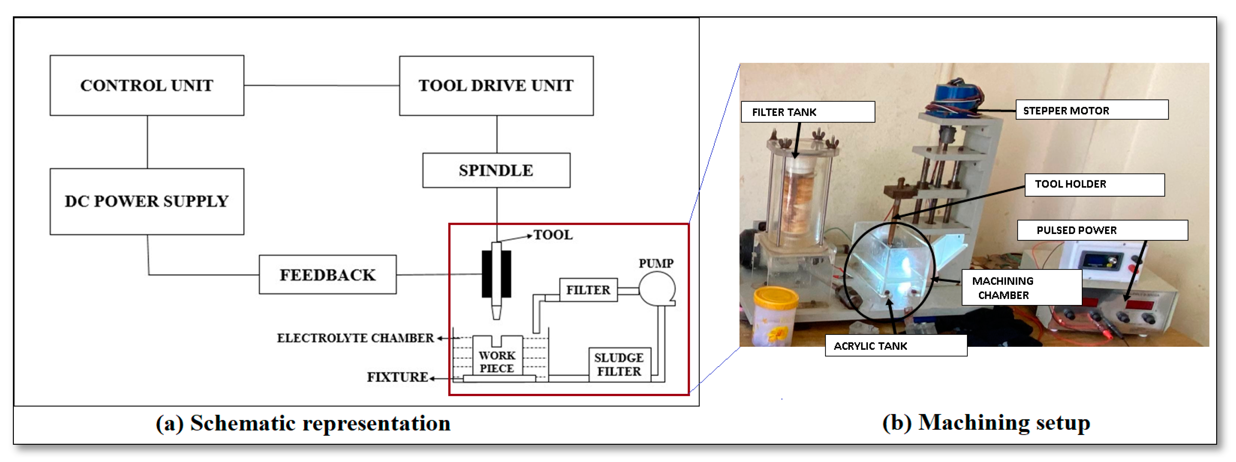
2. Materials and Methods

The experimental arrangement details of the ECMM setup manufactured by SinergyNano Systems (Navi Mumbai, India) in the present study are shown in Figure 1. Electrochemical Micro Machining is a controlled process that involves conductive material removal in the electrolyte chamber where the negative charge is attached to the workpiece, and the positive charge is attached to the tool electrode. The main components used in this ECMM framework are the DC pump, stepper motor, pulsed power supply, and the Acyclic tank size of 200 × 100 × 80 mm. The tank capacity is 1.5 L. The vertical motion of the tool holder is powered by a stepper motor controlled by the microcontroller. The parameters such as supply voltage, feed rate, and duty cycle are given as input for the machine to initiate the hole in the workpiece.

2.1. Selection of Workpiece and Electrode

Incoloy 825 is a nickel-iron-chromium-molybdenum-copper superalloy with high amounts of chromium, nickel, copper, and molybdenum that offers excellent corrosion resistance in both mildly oxidized and reducing conditions, as shown in Table 1, where the chemical composition of Incoloy 825 workpiece is reported, measured using the testing method of ASME E3047-16. Since Incoloy 825 has a high nickel content, it is enough to resist chloride ion corrosion cracking stress. The presence of molybdenum and copper enables the material to withstand reducing agents and acids. This material is useful in evaporators such as phosphoric acids, used as the shaft in propellers, for lifting tanks in trucks, heaters such as pickling tanks, calorifiers, hot vessels such as ammonium sulphate, sulphuric acid, and exhaust systems. The Incoloy 825 workpiece specimens with a thickness of 5 mm were processed through a drilling process using the ECMM process.
The tool electrode of the ECMM process should possess thermal conductivity at its peak and high electrical conductivity and corrosion resistance. Based on these criteria, copper (Cu) material of 0.5 mm diameter was selected as a tool electrode. The diameter of the tool electrode has been measured in three positions and the average values were taken for the analysis. The silver-coated copper tool was composed of a copper core covered by concentric silver plating. The conductivity of copper is combined with the bright and polished surface of silver in the electrode. In addition, the silver (Ag) coating provides high corrosion resistance.

2.2. Electroplating Arrangement for Ag-Coated Copper Electrode

Since a thin level of coating is essential for the copper tool electrode, it is difficult to carry out chemical vapor deposition and physical vapor deposition methods. Hence, Electrodeposition was selected for the coating of silver on the copper tool electrode. The bath composition used for the electrodeposition of silver is presented in Table 2. The process was carried out at a current density of 0.3 A/m2 for 30 min using a DC rectifier. A two-electrode system comprising copper as a cathode and silver mesh as an anode was used. Prior to electrodeposition, the copper electrode was degreased with acetone and etched with a solution containing 75% H3PO4 + 25% H2SO4. To enhance the adhesion of silver to the copper tool, a nickel bonding layer was deposited prior to silver electroplating [26]. During the experiment, the bath was mechanically agitated using a magnetic stirrer at 300 RPM. After electrodeposition, the tool was rinsed with distilled water and dried using a hot air oven. The average coating thickness of silver was observed as 8 ± 2 µm.

2.3. Selection of Electrolyte

The electrolyte type has an impact on the machining rate and overcut. The sodium nitrate electrolyte was found to produce a better machining rate and lower overcut. Passivating electrolytes give better precision for machining because they create an oxide layer that provides a better-machined surface, which does not form while using other electrolytes. Sodium nitrate (NaNO3) was selected as an electrolyte for this micromachining process. Since it is a passivating electrolyte with less throwing power, it removes more material, resulting in a high machining rate and precision.

2.4. Selection of the Process Parameters

Since variable parameters are so important in the ECMM method, the following have been chosen as input process parameters for this analysis [27,28,29,30]. Applied voltage (AV) is a potential difference between a tool as a cathode and a workpiece as an anode. Based on the machine settings 10 V, 12 V, and 14 V were chosen. The concentration of the electrolyte (CE) is the amount of salt dissolved per liter of water. The electrolyte was used as 20 g, 25 g, and 30 g per liter of distilled water. The frequency (f) was selected for machining as 50 Hz, 60 Hz, and 70 Hz. The duty cycle (DC) indicates the duration at which the energy is applied across the zone. The duty cycle percentage selected for this machining is 33%, 50%, and 66% [31,32]. The micro-holes’ quality was analyzed using OPTIV LITE 3020, Hexagon Manufacturing Intelligence, Telford, UK. It was designed to measure the dimensions with an accuracy of 0.001 mm (1 µm) with an inbuilt Charged Coupled Device (CCD) camera machine vision measurement (VMS) system based on the input parameters with the accuracy of 1µm. The optical microscope Olympus BX41M LED Reflected Light Metallurgical Microscope (Olympus, Tokyo, Japan) has also been used to measure the surface performance measures with the magnification range of 50×–500×. The calibration has been done using the Metalplus inbuilt software.
MRR, overcut, conicity, and circularity were chosen as response measures that must be carried out in a theoretical and graphical manner for the experiment to be efficient [33,34]. MRR is the amount of material removed per minute when turning, cutting, milling, grinding, or honing metal. The actual and theoretical MRR can be computed as Equations (1) and (2).
MRR Actual = W 1 W 2 ρ · T   [ mm 3 / min ]
where W1 = weight of the workpiece before machining in gr; W2 = weight of the workpiece after machining in g; T = time for machining in min; ρ = Density of material in g/cc.
MRR Theoretical = I · A ρ · V · F · 60   [ mm 3 / min ]
where I = Current in A; A = atomic weight in amu; V = valence; F = Faraday’s constant equal to 96,500 C mol−1; A/V = e (equivalent weight). The diameter deviation from the electrode tool and the machined hole is called an overcut (OC) and can be calculated using Equation (3), as follows [35]:
OC = Di Dt 2   [ μ m ]
where, Dt = external tool diameter in mm; Di = average diameter of the workpiece in mm. Overcut is an important parameter when assessing micro-hole quality [36]. It is to be noted that in the relevant literature, researchers prefer either to calculate the overcut regarding diameter [37] or the radial overcut [35,38,39,40,41], which is calculated by Equation (3). In any case, the trends observed in the analysis will be similar.
The degree of straightness of the through-hole that is machined is called conicity (CY) and it can be calculated using Equation (4) [42,43,44]:
CY = Diameter   at   entry Diameter   at   exit 2 · hole   thickness
This quantity, based on its definition by Equation (4), is similar to the taper rate or the tangent of taper angle, calculated in various machining processes and should be minimum for straighter holes [43,44,45,46]. Conicity is one of the important parameters regarding the shape accuracy of produced features, especially holes [44,46,47,48,49] as under various conditions the produced holes are usually cone-shaped instead of cylindrical. This parameter can also indicate the morphology of the holes, as when the entry diameter is lower than the exit diameter, the negative value of CY indicates a hole with reversed conicity [42]. In general, conicity can be considered a major goal during the fabrication of microelectronic parts, thus it is fundamental to determine the optimum conditions for minimum conicity of micro-holes [45].
The number of experiments was estimated using the Taguchi approach and the experimental design was determined using the L9 orthogonal array (OA). Since the study dealt with four parameters and three levels L9 OA was fixed as shown in Table 3. It is to be noted that, every measurement was repeated three times and the average values were reported.

3. Results and Discussion

The Incoloy 825 workpiece specimens with a thickness of 5 mm were processed through a drilling process using the ECMM process. The experimental values obtained under the L9 approach were discussed afterward and analyzed; a comparison of the performance of Ag-coated and uncoated copper electrodes was also performed.

3.1. Microstructure Analysis of Ag-Coated and Uncoated Copper Tool Electrode

The surface morphology of the electrodes in the ECMM process was observed using the SIPCON vision measuring system. The surfaces have been polished before the investigation as per ASTM standard. Figure 2 shows the surface morphology of uncoated and silver-coated electrodes before machining in the ECMM process.
It was observed that the cracks on the tool surface were reduced with the coated electrodes. This has resulted in the formation of a smooth surface with the Ag-coated electrode as seen in the surface morphology images. The coating of silver on the copper tool increases the electrical conductivity of the tool electrode when compared to the uncoated Copper Tool Electrode. Figure 3 displays the surface morphology of uncoated and silver-coated copper tool electrodes after machining in the ECMM process. From analyzing the surface morphology images of tool electrodes after the machining process, more pits and pores could be observed due to the interchange of the ions from the tool to the workpiece.

3.2. Electrical Conductivity Analysis of Ag-Coated and Uncoated Copper Tool Electrode

The resistance of the copper tool electrode was measured before and after the coating process using a V-I graph with the help of a desktop Multimeter which has a range of 1micro ohm to 100 ohms. Table 4 shows that the electrical conductivity (σ) of the Cu tool electrode was increased with the silver coating due to the higher conductivity of Ag than Cu. The slope graph was generated using the run values obtained in resistance. Then, the slope equation, resistance, and area of the tool are substituted in the conductivity Equation (5).
ρ r e s = R · A L   [ Ω   mm ]
where, ρ r e s  = resistivity in Ω mm; R = resistance; A = πr2 the area in mm2; r the radius in mm; L the length of wire in mm.
σ = 1 ρ r e s   [ Ω 1 / mm ]
It was observed that the conductivity of the copper tool is the least among the two. The movement of atoms in the crystal lattice causes the ductility and stiffness of the copper tool electrode to increase, lowering the conductivity. The decrease in the electrical conductivity was observed after the machining process. The electrical resistance of the tool increases as the temperature of the tool electrode increases during machining, causing the atoms to vibrate and collide with moving electrons. The hindrance of moving electrons reduces the conductivity of the tool electrode.

3.3. Influence of Ag-Coated Electrode and Process Parameters on Actual MRR

From Table 5, it was observed that the MRR of the Ag-coated copper tool was higher than the MRR of the uncoated copper tool in most cases. Furthermore, except for a few cases, the results obtained by different electrodes are statistically different, as can be clearly observed in Figure 4. The maximum MRR was obtained under a duty factor value of 33% at the high-value voltage and electrolyte concentration as well as a moderate value of pulse frequency, namely 14 V, 30 g/L, and 60 Hz. From the Main effects plots of Figure 4, it can be seen that different trends are obtained when the uncoated and coated electrode is used. Regarding voltage, the use of silver-coated electrode leads to a considerable increase of actual MRR, especially for voltage values over 12 V, for which the results obtained by different electrodes are statistically different as can be seen by the error bars in Figure 4, compared to the use of the uncoated tool, although the trend is common. Regarding electrolyte concentration, the use of a silver-coated tool not only increases the MRR with increased electrolyte concentration, but also changes the trend considerably, with an increasing trend observed for the silver-coated tool while a slightly decreasing trend was observed for the uncoated tool. The pulse frequency affects MRR in a different way when silver-coated and uncoated electrodes were used, as MRR was minimized at a moderate frequency value for the silver-coated electrode, whereas it was maximized for the same frequency value for the uncoated tool. Finally, the MRR obtained with the silver-coated tool is higher for every duty factor value used and the trend is similar for both electrodes, with MRR being minimum at moderate duty factor values.
Based on the statistical analysis of the Taguchi DoE using ANOVA, it is deduced that for the actual MRR for the uncoated electrode, the most significant parameter is the frequency followed by the voltage, while the duty factor and the concentration of the electrolyte have the less impact on the actual MRR. However, for the Ag-coated electrode, the most significant parameter is the concentration of the electrolyte, followed by the voltage, whilst the duty factor and the frequency are the less important parameters.
Electrolyte concentration was proven to be the most influencing parameter for the coated copper tool electrode due to fine grain structure compared to uncoated electrodes. The anodic dissolution is proportional to the conductivity of the machining zone. Since the Ag has higher electrical conductivity than the Cu electrode, the MRR obtained was higher. A higher electrolyte concentration contributes to more ions in the electrolytic medium, resulting in a faster dissolution rate. As the number of ions in the medium increases, there is an increased density of current that leads to a high amount of material removal if led to the higher dissolution of electrolytes and particles removed from the workpiece, thereby increasing the MRR.
Moreover, the higher voltage leads also to a higher MRR due to the increase of the rate of ionization and the enhancement of dissolution of the workpiece material. However, it can also affect the electrolyte properties due to an increased amount of heat produced at higher voltage, something that contributes to the higher removal rate. This effect was greater for the Ag-coated electrode due to its larger conductivity. The pulse frequency is affecting MRR both directly and indirectly, as it can affect the number of pulses per unit of time and thus, the amount of material removed at a specific time period. On the other hand, it can affect electrolyte temperature and flow conditions, as well as electrode wear, which have contradicting effects on MRR. That is the reason why it leads to a larger variation of MRR for the uncoated electrode, which is more prone to wear, than for the Ag-coated one. Finally, the duty cycle is directly related to the ratio of pulse on time and total pulse duration; thus, increased pulse on time leads to more material removal but also increases electrode wear so the MRR cannot be considerably increased.
These results are considerably important, as MRR is related to a crucial goal of the process, i.e., productivity, which is essential in industrial applications, such as hole drilling, apart from obtaining good surface quality and appropriate dimensional accuracy. In the case of ECMM hole drilling, it can be suggested that, for obtaining high MRR, it is more favorable to use a coated electrode at high voltage and electrolyte concentration, relatively low frequency and high duty cycle values.

3.4. Influence of Ag-Coated Electrode and Process Parameters on Theoretical MRR

From Table 6, it was shown that the larger theoretical MRR was obtained for a voltage value of 14 V, electrolyte concentration of 30%, pulse frequency of 60 Hz, and duty factor value of 33%, the same conditions where the actual MRR was the highest. A higher electrolyte concentration shows a considerable amount of ions in the electrolytic medium, resulting in a faster dissolution rate. When the number of ions in the medium rises, current density could result in greater material removal. It was found that the theoretical MRR of the Ag-coated copper tool was better than the MRR obtained by the uncoated copper tool in most cases. The fine grain structure of coated tool electrode provides higher dissolution and removal of particles from the workpiece, leading to an increase in the material removal rate. Although for the theoretical MRR it is anticipated that the results between cases where the two different electrodes were used will be more similar than the results for the actual MRR, something that is justified by the error bars of Figure 5, especially for low to moderate voltages, low to moderate frequencies and duty cycles, in most cases where the results have statistically significant difference, the MRR obtained with the coated electrode is higher. Since the Ag has higher electrical conductivity than Cu electrode, the MRR was higher.
From the Main effects plots of Figure 5 it can be seen that theoretical MRR has different trends than Actual MRR and different trends are also obtained when the uncoated and coated electrode is used. Regarding voltage, the use of a silver-coated electrode leads to a slight increase in the actual MRR, especially for voltage values over 12 V, compared to the use of the uncoated tool, for which MRR becomes almost constant after 12 V. Regarding electrolyte concentration, the use of a silver-coated tool not only increases the MRR with increased electrolyte concentrations, but also changes the trend considerably, with an increasing trend observed for the silver-coated tool while a slightly decreasing and increasing trend was observed for the uncoated tool. The pulse frequency affects MRR in a different way when silver-coated and uncoated electrodes were used, as MRR slightly reduced for increasing pulse frequency when the silver-coated electrode was used, whereas it was slightly increased and then considerably decreased for the uncoated tool. Finally, the MRR obtained with the silver-coated tool is higher for every duty factor value used and the trend is similar for both electrodes, with MRR being minimum at moderate duty factor values.
Again, based on ANOVA results, the significance of the parameters is not the same for the uncoated and the Ag-coated electrode. More specifically, for the uncoated electrode, the most significant machining parameter is the frequency followed by the concentration of the electrolyte and the voltage while the duty factor is the less important parameter. On the other hand, for the Ag-coated electrode, the concentration of the electrolyte is the most important parameter followed by the voltage, while the duty factor and the frequency are again the parameters with the less impact.

3.5. Influence of Ag-Coated Electrode and Process Parameters on Overcut

From the Main effects plots of Figure 6, it can be seen that different trends regarding overcut are obtained when uncoated and the coated electrode is used. Regarding voltage, the use of silver-coated electrode leads generally to a lower overcut, and an increase of voltage results in an increase of overcut, especially for voltage values around 12 V, compared to the use of the uncoated tool, for which overcut first increases and then decreases slightly after 12 V. Regarding electrolyte concentration, opposite trends are observed when silver-coated and uncoated electrodes are used. More specifically, the use of a silver-coated tool leads to a maximum overcut at a moderate level of electrolyte concentration, while the minimum overcut at the same level is observed for the uncoated tool, whereas overcut is generally lower for the coated tool. The pulse frequency affects overcut in a different way when silver-coated and uncoated electrodes were used, as overcut remains almost constant, with a small decreasing trend for increasing pulse frequency when the silver-coated electrode was used, whereas it was considerably reduced at higher frequency values for the uncoated tool. Finally, the overcut values obtained with the silver-coated tool are reduced for duty factor values over 50% whereas overcut is clearly increased when the duty factor is increased for the uncoated electrode.
The micro-holes’ quality was analyzed using a machine vision measurement (VMS) system based on the input parameters as shown in Figure 7. The micro-hole quality was designated as better, good, and poor for the applied process parameters based on the degree of deviation from the appropriate hole diameter. From Table 7 it can be seen that the lowest overcut was obtained at 10 V, 25 g/L electrolyte concentration, 60 Hz pulse frequency and duty factor of 50% for the uncoated electrode, and at 10 V, 20 g/L electrolyte concentration, 50 Hz pulse frequency and duty factor of 33% for the silver-coated electrode, with the overcut value for the uncoated electrode being slightly lower than that of the coated one. However, in general, the overcut values obtained with the uncoated electrode were higher, with the highest overcut obtained at 14 V, 25 g/L electrolyte concentration, 50 Hz pulse frequency, and duty factor of 66%.
Regarding the impact of each parameter on the OC based on ANOVA, interestingly, an almost opposite trend is observed for the uncoated and the Ag-coated electrode. Namely, the parameters for the uncoated electrode in descending order of significance are the duty factor, the frequency, the voltage, and the concentration of the electrolyte, while for the Ag-coated electrode are the voltage, the concentration of the electrolyte, the duty factor, and the frequency.
The lower overcut for the coated electrode can be attributed to the fine grain structure of the silver-coated copper tool electrode, which limits electron movement to the tool’s edge, increasing the current available at the frontal gap between the workpiece and the tool. The increase in voltage leads to less localized current flux and higher stray current so that more material is removed from the workpiece [35]. Moreover, increased electrolyte concentration leads to a higher concentration of ions and reduces the localization of material removal, thus producing higher overcuts up to a point [38], especially for the Ag-coated tool, as for the uncoated tool, the higher wear can cause a variation of this behavior. The higher duty factor, caused by a higher pulse on time leads to a higher amount of removed material, thus higher overcut is obtained. The fact that the duty factor value of 50% is critical can be attributed to the material removal time being equivalent to the flushing time at 50% of the service cycle. Finally, with an increase in frequency value, the overcut decreases due to a higher pulse generated per unit time something that leads to an improvement in localization while stray current decreases, resulting in a low overcut.
Lower overcut is also an important goal of the process, apart from higher productivity, as dimensional accuracy, especially for micro-holes, is necessary for various high-end applications, e.g., microelectronics. From the findings of this work, it is suggested that a coated electrode and low voltage, electrolyte concentration, and duty cycle along with high-frequency values, lead to the minimization of overcut.

3.6. Influence of Ag-Coated Electrode and Process Parameters on Conicity

As shown in Table 8, the lowest value for conicity for the uncoated electrode is obtained with a voltage value of 14 V, electrolyte concentration of 25 g/L, pulse frequency of 50 Hz, and duty cycle value of 66% whereas the lowest value of conicity for the coated electrode is obtained with a voltage value of 12 V, electrolyte concentration of 25 g/L, pulse frequency of 70 Hz and duty cycle value of 33%. On the other hand, the maximum value for conicity for the uncoated electrode is obtained with a voltage value of 12 V, electrolyte concentration of 25 g/L, pulse frequency of 70 Hz, and duty cycle value of 33%, whereas for the coated electrode, the higher value is obtained for voltage value of 10 V, electrolyte concentration of 30 g/L, pulse frequency of 70 Hz, and duty cycle value of 66%. Although the minimum conicity value was obtained by the uncoated electrode, in most cases, the conicity is lower when the coated electrode is used. Moreover, for the uncoated electrode, conicity values fluctuate considerably higher than the conicity values for the coated electrode.
From the Main effects plots of Figure 8, it can be seen that different trends regarding conicity are obtained when uncoated and coated electrodes are used. Regarding voltage, the use of silver-coated electrodes leads generally to lower conicity, and an increase in voltage results in a slight decrease of conicity, compared to the use of an uncoated tool, for which conicity first increases and then decreases considerably after 12 V. Regarding electrolyte concentration, opposite trends are observed when silver-coated and uncoated electrodes are used. More specifically, the use of a silver-coated tool leads to a minimum conicity at a moderate level of electrolyte concentration, while the maximum conicity at the same level is observed for the uncoated tool, whereas conicity is generally lower for the coated tool. The pulse frequency affects conicity to a different extent when silver-coated and uncoated electrodes were used, as conicity remains almost constant, with a small increasing trend for increasing pulse frequency when the silver-coated electrode was used, whereas it was slightly reduced and then increased at higher frequency values for the uncoated tool. Finally, the overcut values obtained with the silver-coated tool are almost constant whereas overcut is clearly decreased when the duty factor is increased for the uncoated electrode.
For the conicity based on ANOVA results, it is deduced that for the uncoated electrode, the most important machining parameter is the duty factor, followed by the voltage, the frequency, and the concentration of the electrolyte. However, when the Ag-coated electrode is employed, the voltage becomes the most important parameter, followed by the concentration of the electrolyte, the duty factor, and the frequency.
The increase in voltage leads to higher energy, higher wear, and variations in the electrolyte flow, thus it increases material removal and conicity, especially for the uncoated electrode. However, in the case of the Ag-coated electrode, the coating leads to lower deformation of the tool and finally, the conicity is barely affected. The increase of electrolyte concentration leads generally to higher current density and material removal, thus can increase conicity up to a point for the uncoated electrode, whereas further increase can lead to a different behavior due to increased wear and variation of electrode shape. On the other hand, the use of coating prevents undesirable phenomena and leads to an almost constant variation of conicity with respect to the electrolyte concentration. Moreover, the higher frequency can affect material removal to a larger extent and thus conicity is increased, especially for the uncoated electrode.
In order to achieve low conicity, the use of a coated electrode is recommended, along with high voltage, moderate electrolyte concentration, low frequency, and low duty cycle values.

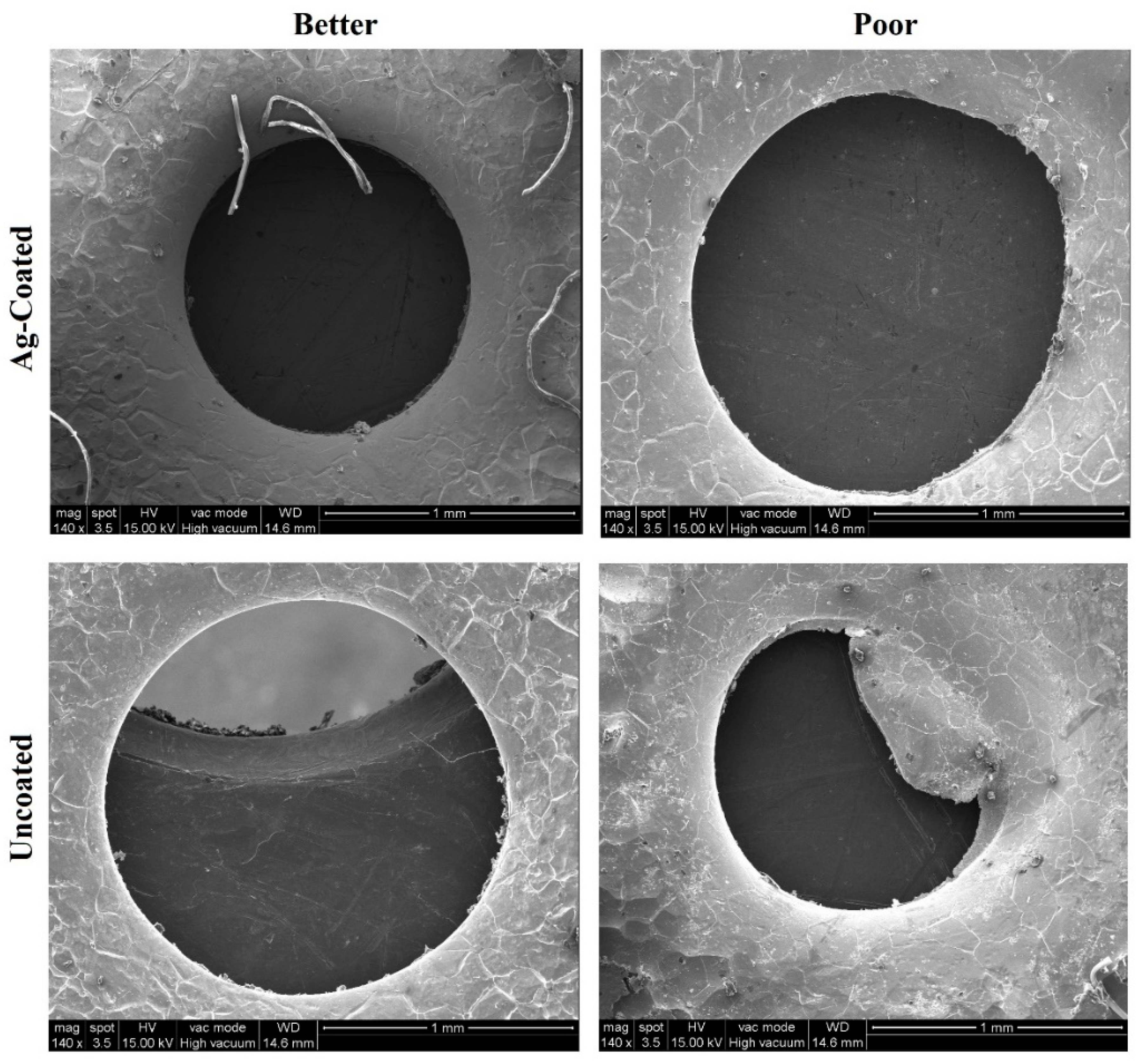
3.7. SEM Analysis of the Workpiece Specimen and Tool Electrode

Figure 9 shows scanning electron microscope (SEM: JEOL JAPAN, Jeol-6490 JED-2300) images of the machined workpieces with uncoated and Ag-coated electrodes. It was used to examine the surface topography of the electrochemically micro-machined Incoloy 825 workpiece.
According to the investigation of all images considered, the machining accuracy was higher when the NaNO3 electrolyte reacted with the silver-coated copper tool electrode on Incoloy 825 workpiece. From these images, qualitative observations regarding the circularity error can be conducted. The circularity error is defined as the extent of the deviation of a machined hole from the perfect circle and can be directly affected by the process parameters [37]. Ag-coated electrodes could produce a smoother shape, crack-free with lesser circularity error than uncoated electrodes. The uncoated tool lacks prescribed circularity due to the formed cracks. It was indicated that the machining process with low input parameters could reduce the risk of sparking and stray current. It was found the effect of sparking and stray current tends to be evident in the machined workpiece, leading to some irregularities in the edges of the machined surface at high input parameters (14 V, 70 Hz, and 25 g/L).
Figure 10 defines the surface examination of machined silver-coated copper tool electrodes and uncoated copper tool electrodes using SEM. From the analysis, it was observed that uncoated copper tool electrode tends to have more cracks and corroded regions. These cracks and corroded regions represent the presence of carbon content in electrolyte dissolution which has reflected its effect on the tool during the ECMM process. However, when silver-coated copper tool electrode is observed, it tends to exhibit fewer cracks and corroded regions than the uncoated copper tool electrode. It clearly shows that the silver coating acts as a corrosion barrier when combined with carbon-based electrolyte dissolution, resulting in less carbon formation on the workpiece during machining.
From the observations of the SEM images, the silver-coated copper tool electrode which is used to work on input parameters of 14 V, 50 Hz, 25 g/L, and duty cycle of 66%, was found to have more uneven localized deposition on the tool surface during the study. It is due to the reaction of a coated tool under relatively harsh process conditions, which causes stray current corrosion in the tool electrode. On the other hand, under a favorable combination of low input conditions and coated tool, which resulted in less stray current and corrosion in the tool electrode, the forming of irregular localized deposition on the tool surface is minimized, and even the cracks will be seen less when working with low and optimum input parameter values.

3.8. EDS Analysis of the Workpiece Specimen and Tool Electrode

In this subsection, the EDS results regarding the machined workpieces and tool electrodes will be analyzed. It is to be noted that the measurements were conducted on selected points on the side walls of the produced hole and the bottom surface of the tool electrode, respectively. In Figure 11 and Figure 12, the results regarding the workpiece under the conditions of trials 5 and 8 are presented, both when the uncoated and Ag-coated tools were used. Moreover, in Figure 13 and Figure 14, the results regarding the uncoated and coated electrode under the conditions of trials 5, 3, and 8 are presented.
In Figure 11 and Figure 12, the EDS results on the workpiece from ECMM both uncoated and Ag-coated electrodes under two different experiments are shown. More specifically, the conditions of trial 5 were less harsh than the ones of trial 8, with the latter resulting in higher MRR and overcut both in the case with the uncoated and the coated electrode.
Regarding the EDS results for the workpiece after trial 5, when the Ag-coated electrode was used, it can be seen from Figure 11, that in comparison to the initial composition of the workpiece, the percentages of various elements have changed, with Ni, Fe, and Mo being reduced while Cu and C were increased. Whereas the lower percentages of Ni, Fe, and Mo can be attributed to the removed material and the slightly increased percentage of Cu can be attributed to the electrode material, the 4.70% of residual C on the surface of micro-holes shows that the presence of carbon content in electrolyte dissolution has reflected its effect on the workpiece during the ECM machining process, leading to less material removal from the workpiece using the better combination of the low input parameters and the silver-coated tool electrode. In the case of the uncoated electrode, most results are similar, except for the larger amount of C on the workpiece, which was released from the dissolution of the electrolyte.
On the other hand, ECMM under harsher conditions, such as the ones of trial 8, shows more considerable alteration of the composition of the workpiece surface. From Figure 12, it can be seen that the percentages of Ni and Fe are lower than the ones of trial 5 for the same type of electrode, while the percentage of C on the workpiece is higher in the case of the coated electrode and slightly lower in the case of uncoated electrode.
From EDS analysis of the tool electrode as shown in Figure 13 and Figure 14, the chemical composition of the copper and Ag-coated copper electrodes was similar to the initial one, and no elements relevant to the workpiece elements composition (Ni, Fe, Cr) were observed under the medium parametric condition of trial 5 (12 V, 25 g/L, 70 Hz, and duty factor of 33%). Due to the lower percentage of carbon and oxygen in the alloy, the reaction of silver (coating) with carbonic oxide available in the electrolyte was reduced. However, the lower duty cycle means that the energy will be applied to the workpiece in a shorter time than in the case of trial 8, leading to higher removal of Ag-coating. Although in slightly more intense conditions, such as the ones of trial 8, the reaction of Silver (coating) with the carbonic oxide in the electrolyte is higher, the higher duty cycle finally leads to a lower quantity of Ag coating being removed. Due to over machining of the tool electrode in case 8, after the removal of silver coating from the tool surface, elements from the workpiece (Ni, Cr, Fe) were embedded in the tool electrode surface in larger quantities than in trial 8, namely 4.31%, 3.12%, and 3.91% instead of 0%, 0.17%, and 0%, respectively.

4. Conclusions

In this investigation, micro-holes were created on Incoloy 825 alloy by ECMM process with copper and Silver-coated copper tool electrodes under various combinations of voltage, electrolyte concentration, pulse frequency, and duty factor in order to achieve the most desirable performance parameters regarding MRR, overcut and conicity of the produced holes. The following results were framed from experiments conducted with uncoated and silver-coated copper tool electrodes.
  • The MRR obtained using the Silver-coated copper tool was higher than the uncoated tool electrode in most cases, because of the high electrical conductivity obtained in the Silver-coated copper tool electrode. For both the actual and theoretical MRR, the pulse frequency was the most important parameter when the uncoated electrode was used, whereas the electrolyte concentration was the most important parameter, when the coated electrode was used. From these results, it can be recommended that, in order to achieve higher productivity in the ECMM process, a coated electrode and high values of voltage, electrolyte concentration, and duty cycle should be used, along with relatively low-frequency values.
  • The overcut results obtained using the silver-coated copper tool electrode were better when compared to the uncoated tool electrode, since the Silver-coated copper tool electrode has a fine grain structure that restricts the flow of electrons. For the overcut, the most important parameter was the duty factor when the uncoated electrode was used and the voltage when the coated electrode was used. From these results, it can be recommended that, in order to achieve lower overcut, a coated electrode and low values of voltage, electrolyte concentration, and duty cycle should be used, along with high-frequency values.
  • The conicity levels are generally higher with an uncoated copper tool electrode. For conicity, when the uncoated electrode was used the duty factor was the most important parameter, whereas when the coated electrode was used, the voltage was the most important parameter. In order to minimize conicity, it is recommended that a coated electrode should be used at high voltage, moderate electrolyte concentration, low frequency, and low-duty cycle conditions.
  • The silver-coated copper tool electrode tends to have fewer cracks, pit formations, and corroded regions than the uncoated copper tool electrode because of silver coating, which acted as a corrosion shield when coming into contact with carbon contented electrolyte dissolution.
  • The EDS analysis revealed that when a silver-coated copper tool electrode was used, it could produce fewer particles of tool electrode over the machined surface without affecting real constituents of the workpiece specimens. Under harsher conditions, the embedment of workpiece elements on the tool electrode is increased. Finally, the removal of Ag coating was correlated to the energy input, mainly represented by the duty cycle, as higher amount of Ag was removed at lower duty cycle values, when the energy is applied in a shorter duration.

Author Contributions

Conceptualization, G.T. and M.T.; methodology, G.T., M.T., P.I.A. and M.J.; software, M.T. and E.L.P.; validation, N.E.K., E.L.P. and P.K.-O.; formal analysis, G.T., M.T., N.E.K., E.L.P. and P.K.-O.; investigation, G.T., M.T., P.I.A. and M.J.; resources, M.T.; data curation, G.T. and M.T.; writing—original draft preparation, G.T., M.T., P.I.A. and M.J.; writing—review and editing, N.E.K., E.L.P. and P.K.-O.; visualization, G.T., M.T. and E.L.P.; supervision, M.T.; project administration, M.T.; funding acquisition, N.E.K. All authors have read and agreed to the published version of the manuscript.

Funding

This research received no external funding.

Institutional Review Board Statement

Not applicable.

Informed Consent Statement

Not applicable.

Data Availability Statement

The data presented in this study are available on request from the corresponding author.

Conflicts of Interest

The authors declare no conflict of interest.

References

  1. Kangazian, J.; Sayyar, N.; Shamanian, M. Influence of Microstructural Features on the Mechanical Behavior of Incoloy 825 Welds. Metallogr. Microstruct. Anal. 2017, 6, 190–199. [Google Scholar] [CrossRef]
  2. Ding, Q.; Lao, Z.; Wei, H.; Li, J.; Bei, H.; Zhang, Z. Site Occupancy of Alloying Elements in Γ′ Phase of Nickel-Base Single Crystal Superalloys. Intermetallics 2020, 121, 106772. [Google Scholar] [CrossRef]
  3. Wei, C.-N.; Bor, H.-Y.; Chang, L. The Effects of Carbon Content on the Microstructure and Elevated Temperature Tensile Strength of a Nickel-Base Superalloy. Mater. Sci. Eng. A 2010, 527, 3741–3747. [Google Scholar] [CrossRef]
  4. Choudhury, B.; Chandrasekaran, M.; Devarasiddappa, D. Development of ANN Modelling for Estimation of Weld Strength and Integrated Optimization for GTAW of Inconel 825 Sheets Used in Aero Engine Components. J. Braz. Soc. Mech. Sci. Eng. 2020, 42, 308. [Google Scholar] [CrossRef]
  5. Reed, R.C. The Superalloys, Fundamentals and Applications; Cambridge University Press: Cambridge, UK, 2006. [Google Scholar]
  6. Sims, C.; Stoloff, N.S.; Hagel, W.C. (Eds.) Superalloys II; John Wiley & Sons: Hoboken, NJ, USA, 1987. [Google Scholar]
  7. Geethapriyan, T.; Muthuramalingam, T.; Moiduddin, K.; Mian, S.M.; Alkhalefah, H.; Umer, U. Performance Analysis of Electrochemical Micro Machining of Titanium (Ti-6Al-4V) Alloy under Different Electrolytes Concentrations. Metals 2021, 11, 247. [Google Scholar] [CrossRef]
  8. Geethapriyan, T.; Muthuramalingam, T.; Kalaichelvan, K. Influence of Process Parameters on Machinability of Inconel 718 by Electrochemical Micromachining Process using TOPSIS Technique. Arab. J. Sci. Eng. 2019, 44, 7945–7955. [Google Scholar] [CrossRef]
  9. Rajurkar, K.P.; Sundaram, M.M.; Malshe, A.P. Review of Electrochemical and Electrodischarge Machining. Procedia CIRP 2013, 6, 13–26. [Google Scholar] [CrossRef]
  10. Geethapriyan, T.; Muthuramalingam, T.; Moiduddin, K.; Alkhalefah, H.; Mahalingam, S.; Karmiris-Obratański, P. Multiobjective Optimization of Heat-Treated Copper Tool Electrode on EMM Process Using Artificial Bee Colony (ABC) Algorithm. Materials 2022, 15, 4831. [Google Scholar] [CrossRef]
  11. Liu, S.; Geethapriyan, T.; Muthuramalingam, T.; Shanmugam, R.; Ramoni, M. Influence of heat-treated Cu-Be electrode on machining accuracy in ECMM with Monel 400 alloy. Arch. Civil. Mech. Eng. 2022, 22, 154. [Google Scholar] [CrossRef]
  12. Li, H.; Gao, C.; Wang, G.; Qu, N.; Zhu, D. A Study of Electrochemical Machining of Ti-6Al-4V in NaNO3 Solution. Sci. Rep. 2016, 6, 35013. [Google Scholar] [CrossRef]
  13. Harugade, M.; Kavade, M.V.; Hargude, N. Effect of Electrolyte Solution on Material Removal Rate in Electrochemical Discharge Machining. IOSR J. Mech. Civ. Eng. 2013, 5, 1–8. [Google Scholar]
  14. Manikandan, N.; Kumanan, S.; Sathiyanarayanan, C. Multiple Performance Optimization of Electrochemical Drilling of Inconel 625 Using Taguchi Based Grey Relational Analysis. Eng. Sci. Technol. Int. J. 2017, 20, 662–671. [Google Scholar] [CrossRef]
  15. Krishnan, R.; Duraisamy, S.; Palanisamy, P.; Veeramani, A. Optimization of the Machining Parameters in the Electrochemical Micro-Machining of Nickel. Mater. Tehnol. 2018, 52, 253–258. [Google Scholar] [CrossRef]
  16. Geethapriyan, T.; Kalaichelvan, K.; Muthuramalingam, T.; Rajadurai, A. Performance analysis of process parameters on machining α-β titanium alloy in electrochemical micromachining process. Proc. Inst. Mech. Eng. B J. Eng. Manuf. 2018, 232, 1577–1589. [Google Scholar] [CrossRef]
  17. Liu, G.; Li, Y.; Kong, Q.; Tong, H.; Zhong, H. Silicon-Based Tool Electrodes for Micro Electrochemical Machining. Precis. Eng. 2018, 52, 425–433. [Google Scholar] [CrossRef]
  18. Shanmugam, R.; Ramoni, M.; Thangamani, G.; Thangaraj, M. Influence of Additive Manufactured Stainless Steel Tool Electrode on Machinability of Beta Titanium Alloy. Metals 2021, 11, 778. [Google Scholar] [CrossRef]
  19. Egashira, K.; Hayashi, A.; Hirai, Y.; Yamaguchi, K.; Ota, M. Drilling of Microholes Using Electrochemical Machining. Precis. Eng. 2018, 54, 338–343. [Google Scholar] [CrossRef]
  20. Mithu, M.A.H.; Fantoni, G.; Ciampi, J.; Santochi, M. On How Tool Geometry, Applied Frequency and Machining Parameters Influence Electrochemical Microdrilling. CIRP J. Manuf. Sci. Technol. 2012, 5, 202–213. [Google Scholar] [CrossRef]
  21. Swain, A.K.; Sundaram, M.M.; Rajurkar, K.P. Use of Coated Microtools in Advanced Manufacturing: An Exploratory Study in Electrochemical Machining (ECM) Context. J. Manuf. Process. 2012, 14, 150–159. [Google Scholar] [CrossRef]
  22. Bhattacharyya, B.; Malapati, M.; Munda, J.; Sarkar, A. Influence of Tool Vibration on Machining Performance in Electrochemical Micro-Machining of Copper. Int. J. Mach. Tools Manuf. 2007, 47, 335–342. [Google Scholar] [CrossRef]
  23. Ghoshal, B.; Bhattacharyya, B. Generation of Microfeatures on Stainless Steel by Electrochemical Micromachining. Int. J. Adv. Manuf. Technol. 2015, 76, 39–50. [Google Scholar] [CrossRef]
  24. Wielage, B.; Mäder, T.; Fürderer, B.; Nestler, D.; Reinecke, H. Carbon Fibres Used as Electrode Tools for Micro-Electrochemical Machining. In Proceedings of the 17th International Conference on Composite Materials, Edinburgh, UK, 27–31 July 2009. [Google Scholar]
  25. Chen, X.; Xu, Z.; Zhu, D.; Fang, Z.; Zhu, D. Experimental Research on Electrochemical Machining of Titanium Alloy Ti60 for a Blisk. Chin. J. Aeronaut. 2016, 29, 274–282. [Google Scholar] [CrossRef]
  26. Thanigaivelan, R.; Arunachalam, R. Study on Influence of Tool Design on Electrochemical Micromachining. Manuf. Technol. Today 2011, 10, 3–10. [Google Scholar]
  27. Anasane, S.S.; Bhattacharyya, B. Experimental Investigation into Micromilling of Microgrooves on Titanium by Electrochemical Micromachining. J. Manuf. Process. 2017, 28, 285–294. [Google Scholar] [CrossRef]
  28. Duraisamy, S.; Arularasu, M.; Ganesan, K. A Study on Electrochemical Micromachining of Super Duplex Stainless Steel for Biomedical Filters. ARPN J. Eng. Appl. Sci. 2012, 7, 517–523. [Google Scholar]
  29. Ayyappan, S.; Sivakumar, K. Experimental Investigation on the Performance Improvement of Electrochemical Machining Process Using Oxygen-Enriched Electrolyte. Int. J. Adv. Manuf. Technol. 2014, 75, 479–487. [Google Scholar] [CrossRef]
  30. Soni, S.K.; Thomas, B. A Comparative Study of Electrochemical Machining Process Parameters by Using GA and Taguchi Method. IOP Conf. Ser. Mater. Sci. Eng. 2017, 263, 062038. [Google Scholar] [CrossRef]
  31. Uttarwar, S.S.; Chopde, I.K. A Study of Influence of Electrochemical Process Parameters on the Material Removal Rate and Surface Roughness of SS AISI 304. Int. J. Comput. Eng. Res. 2013, 3, 189–197. [Google Scholar]
  32. Geethapriyan, T.; Kalaichelvan, K. Experimental Investigation of Electrochemical Micromachining Process Parameters on Pure-Titanium Using Taguchi-Grey Relational Analysis. Appl. Mech. Mater. 2016, 852, 198–204. [Google Scholar] [CrossRef]
  33. Geethapriyan, T.; Kalaichelvan, K.; Muthuramalingam, T. Influence of Coated Tool Electrode on Drilling Inconel Alloy 718 in Electrochemical Micro Machining. Procedia CIRP 2016, 46, 127–130. [Google Scholar] [CrossRef]
  34. Muthuramalingam, T.; Thangamani, G.; Kalaichelvan, K. Multi Performance Optimization of Electrochemical Micro-Machining Process Surface Related Parameters on Machining Inconel 718 Using Taguchi-Grey Relational Analysis. Metall. Ital. 2016, 2016, 13–19. [Google Scholar]
  35. Nugroho, A.W.; Sudarisman; Nurahman, M.B.; Septiaji, P. Overcut and material removal rate on electrochemical machining of aluminum and stainless steel using isolated brass electrode. In Proceedings of the 2nd International Conference of Industrial, Mechanical, Electrical, Chemical Engineering (ICIMECE), Yogyakarta, Indonesia, 6–7 October 2016. [Google Scholar]
  36. Das, A.; Padhan, S.; Das, S.R. Analysis on hole overcut during micro-EDM of Inconel 718. Mater. Today Proceed. 2022, 56, 29–35. [Google Scholar] [CrossRef]
  37. Sathish, T. Experimental investigation of machined hole and optimization of machining parameters using electrochemical machining. J. Mater. Res. Technol. 2019, 8, 4354–4363. [Google Scholar] [CrossRef]
  38. Tajdari, M.; Chavoshi, S.Z. Prediction and analysis of radial overcut in holes drilled by electrochemical machining process. Cent. Eur. J. Eng. 2013, 3, 466–474. [Google Scholar] [CrossRef]
  39. Aravind, S.; Hiremath, S.S. Machining of holes on SS316L with solid and hollow tool electrodes. Mater. Manuf. Process. 2022, 37, 1859–1870. [Google Scholar] [CrossRef]
  40. Deepak, J.; Hariharan, P. Investigation of electrochemical machining on SS304 using NaCl and NaNO3 as electrolyte. Mater. Manuf. Process. 2022, 37, 1790–1803. [Google Scholar]
  41. Teimouri, R.; Baseri, H. Study of tool wear and overcut in EDM process with rotary tool and magnetic field. Adv. Tribiol. 2012, 2012, 895918. [Google Scholar] [CrossRef]
  42. Machno, M.; Matras, A.; Szkoda, M. Modelling and analysis of the effect of EDM-Drilling parameters on the machining performance of Inconel 718 using the RSM and ANNs methods. Materials 2022, 15, 1152. [Google Scholar] [CrossRef]
  43. D’Urso, G.; Merla, C. Workpiece and electrode influence on micro-EDM drilling performance. Precis. Eng. 2014, 38, 903–914. [Google Scholar] [CrossRef]
  44. Wen, Z.; Pei, H.; Zhang, C.; Wang, B. Analysis of surface quality of multi-film cooling holes in nickel-based single crystal superalloy. Mater. Sci. Technol. 2016, 32, 1845–1854. [Google Scholar] [CrossRef]
  45. Vivekkumar, P.; Soundrapandian, E.; Tajdeen, A.; Prashanth, T. Experimental study of Electrochemical micromachining on Titanium (Ti-6Al-4V) Alloy. In Advances in Materials Research. Springer Proceedings in Materials; Kumaresan, G., Shanmugam, N.S., Dhinakaran, V., Eds.; Springer Nature: Singapore, 2021; pp. 301–308. [Google Scholar]
  46. Sen, M.; Shan, H.S. A review of electrochemical macro- to micro-hole drilling processes. Int. J. Mach. Tools Manuf. 2005, 45, 137–152. [Google Scholar] [CrossRef]
  47. Machno, M.; Bogucki, R.; Szkoda, M.; Bizoń, W. Impact of the deionized water on making high aspect ratio holes in the Inconel 718 Alloy with the use of Electrical Discharge Drilling. Materials 2020, 13, 1476. [Google Scholar] [CrossRef] [PubMed]
  48. Phan, N.H.; Muthuramalingam, T.; Nguyen, T.L.; Tran, V.D. Effect of ultrasonic low frequency vibration and its direction on machinability in WEDM process. Mater. Manuf. Process. 2022, 37, 1045–1051. [Google Scholar] [CrossRef]
  49. Muthuramalingam, T.; Moiduddin, K.; Akash, R.; Krishnan, S.; Mian, S.H.; Ameen, W.; Alkhalefah, H. Influence of process parameters on dimensional accuracy of machined Titanium (Ti-6Al-4V) alloy in Laser Beam Machining Process. Opt. Laser. Technol. 2020, 132, 106494. [Google Scholar] [CrossRef]
Figure 1. ECMM arrangement in the present study.
Coatings 13 00963 g001
Figure 2. Morphology of copper electrode before machining (a) Uncoated (b) Silver Coated.
Coatings 13 00963 g002
Figure 3. Surface Morphology of copper electrode after machining (a) Uncoated (b) Silver Coated.
Coatings 13 00963 g003
Figure 4. Main Effects Plots of the actual MRR.
Coatings 13 00963 g004
Figure 5. Main Effects Plots of the theoretical MRR.
Coatings 13 00963 g005
Figure 6. Main Effects Plots of the overcut.
Coatings 13 00963 g006
Figure 7. VMS Image for Overcut.
Coatings 13 00963 g007
Figure 8. Main Effects Plots of the conicity.
Coatings 13 00963 g008
Figure 9. SEM Image of Machined Coated and Uncoated Workpiece.
Coatings 13 00963 g009
Figure 10. SEM Image of Machined Tool Electrodes (a) Ag-coated under trial 5 (b) Ag-coated trial 3 (c) Ag-coated trial 8 (d) Uncoated under trial 5 (e) Uncoated trial 3 (f) Uncoated trial 8.
Coatings 13 00963 g010
Figure 11. EDS Image of Machined Workpiece with Ag-Coated and Uncoated tool under trial 5.
Coatings 13 00963 g011
Figure 12. EDS Image of Machined Workpiece with Ag-Coated and Uncoated tools under trial 8.
Coatings 13 00963 g012
Figure 13. EDS Image of Machined Tool Electrodes (a) Uncoated under trial 5 (b) Uncoated trial 3 (c) Uncoated trial 8.
Coatings 13 00963 g013
Figure 14. EDS Image of Machined Tool Electrodes (a) Ag-coated under trial 5 (b) Ag-coated trial 3 (c) Ag-coated trial 8.
Coatings 13 00963 g014
Table 1. Chemical composition of Incoloy 825.
ElementsNiFeCrMoCuTiCMgSiSAl
Composition (%)42.230.8919.92.741.6370.810.0220.710.360.0010.116
Table 2. Bath Composition for electrodeposition of silver on copper.
ChemicalConcentration
AgNO315 g/L
KCL15 g/L
Na2S2O340 g/L
C4H4O2Na230 g/L
Table 3. Design of Experiment using Coated and Uncoated Tool Electrode.
Exp No.Applied
Voltage [V]
Electrolyte
Concentration [g/L]
Frequency
[Hz]
Duty
Cycle [%]
110205033
210256050
310307066
412206066
512257033
612305050
714207050
814255066
914306033
Table 4. Conductivity before and after machining.
ElectrodeElectrical Conductivity [Ω−1/mm]
Before MachiningAfter Machining
Uncoated31.412.93
Ag coated34.583.48
Table 5. Response table on actual MRR.
S. NoV
[V]
CE
[g/L]
f
[Hz]
DC
[%]
Actual MRR
[mm3/min]
UncoatedAg Coated
1102050330.000630.000499
2102560500.0008050.000592
3103070660.0005050.00087
4122060660.0008580.000415
5122570330.0005290.00076
6123050500.0005290.000809
7142070500.0005690.000584
8142550660.0006710.001029
9143060330.0009230.001051
Table 6. Response table on theoretical MRR.
S. NoV
[V]
CE
[g/L]
f
[Hz]
DC
[%]
Theoretical MRR
[mm3/min]
UncoatedAg Coated
1102050330.000980.000804
2102560500.0009210.000882
3103070660.0008040.001
4122060660.0010780.000843
5122570330.0008040.001019
6123050500.0010580.001137
7142070500.0007840.000784
8142550660.000960.001117
9143060330.0012150.001352
Table 7. Response table of the overcut.
S. NoV
[V]
CE
[g/L]
f
[Hz]
DC
[%]
Overcut
[μm]
UncoatedAg Coated
110205033284.5232.4
210256050223.3325.5
310307066330.0255.2
412206066429.9264.4
512257033246.3264.2
612305050415.6280.4
714207050302.6343.4
814255066448.4405.7
914306033277.3316.2
Table 8. Response table on conicity.
S. NoV
[V]
CE
[g/L]
f
[Hz]
DC
[%]
Conicity
[Degree]
UncoatedAg Coated
11020503311.554.98
2102560508.273.06
3103070660.805.60
4122060660.863.92
51225703327.931.60
6123050506.672.73
7142070501.643.25
8142550660.071.88
9143060335.861.64
Disclaimer/Publisher’s Note: The statements, opinions and data contained in all publications are solely those of the individual author(s) and contributor(s) and not of MDPI and/or the editor(s). MDPI and/or the editor(s) disclaim responsibility for any injury to people or property resulting from any ideas, methods, instructions or products referred to in the content.

