
Influence of TiC Addition on Corrosion and Tribocorrosion Resistance of Cr2Ti-NiAl Electrospark Coatings

 , , and
Abstract
1. Introduction
2. Experimental Details
2.1. Electrode Production
2.2. Coatings Deposition
2.3. Structure and Elemental Composition
2.4. Tribocorrosion, Electrochemical and Mechanical Properties Studies
3. Results and Discussion
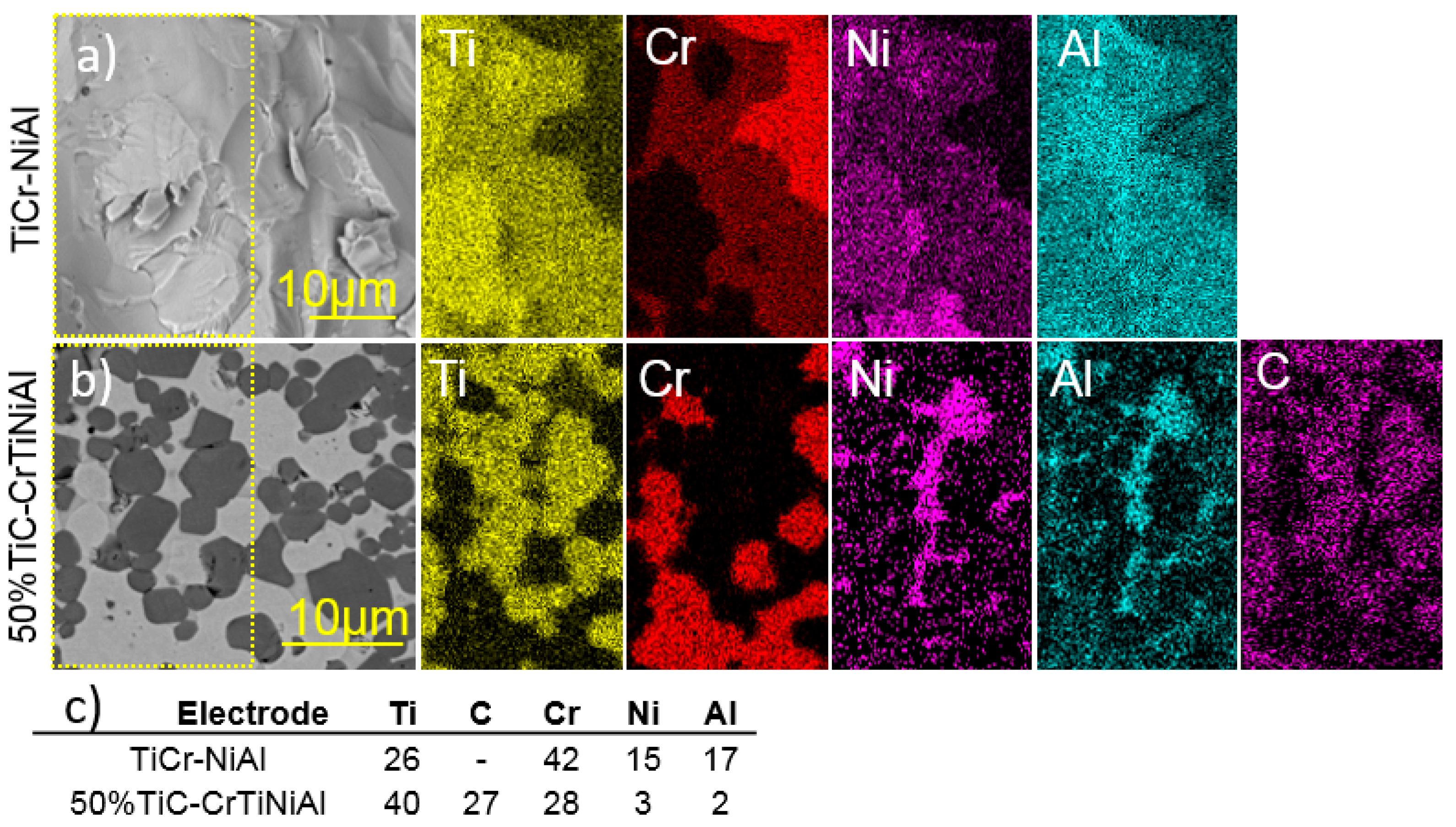
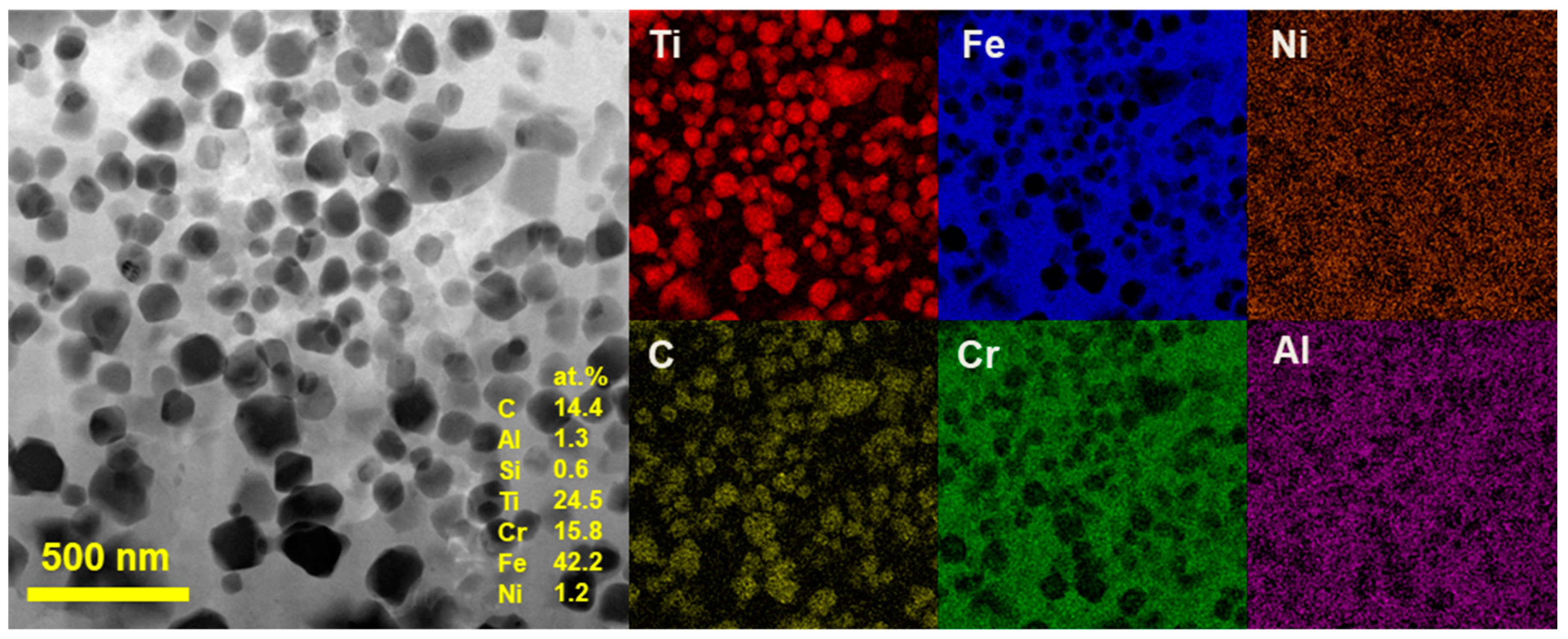
3.1. Structure and Elemental Composition of Electrodes
3.2. Structure and Elemental Composition of Coatings
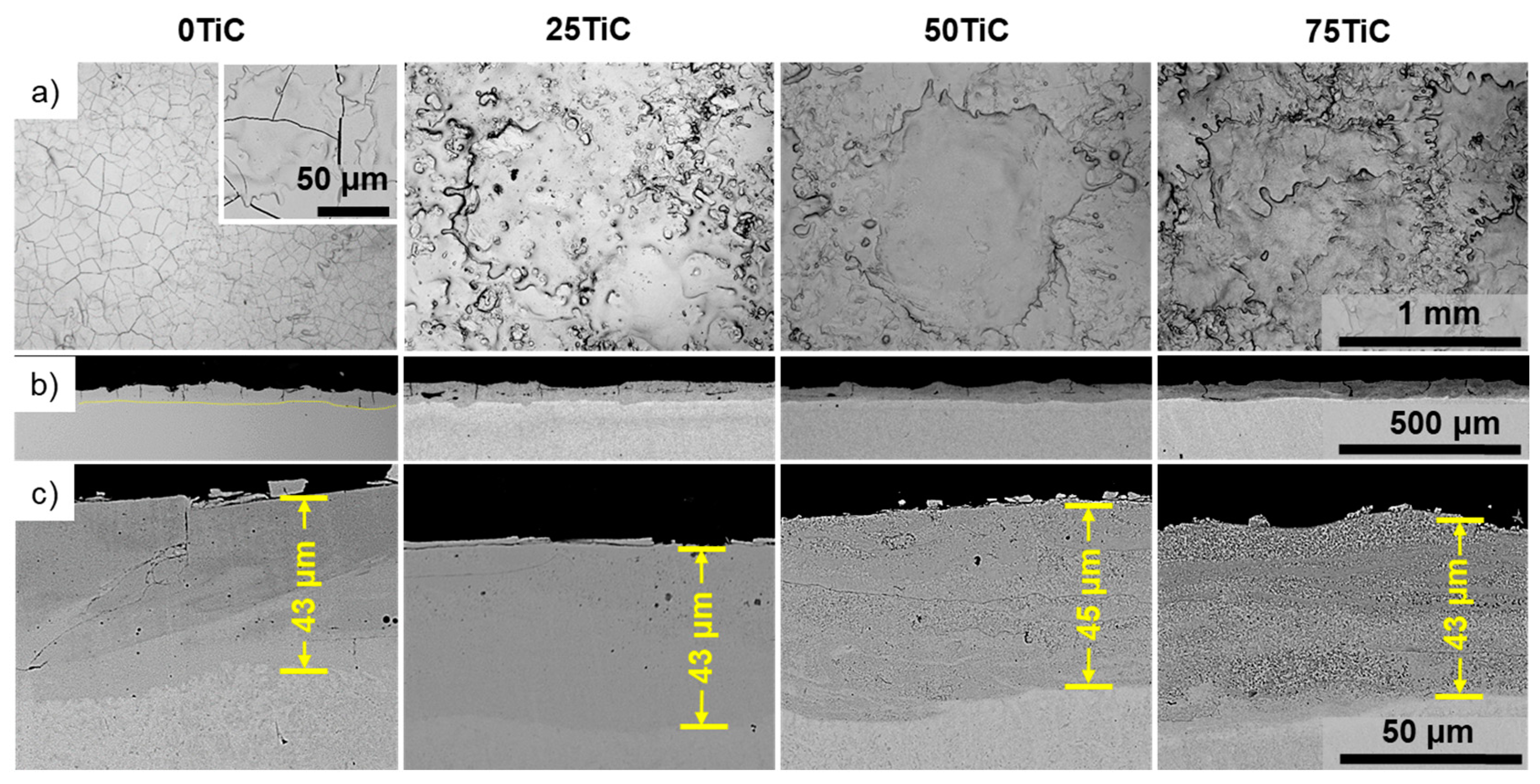
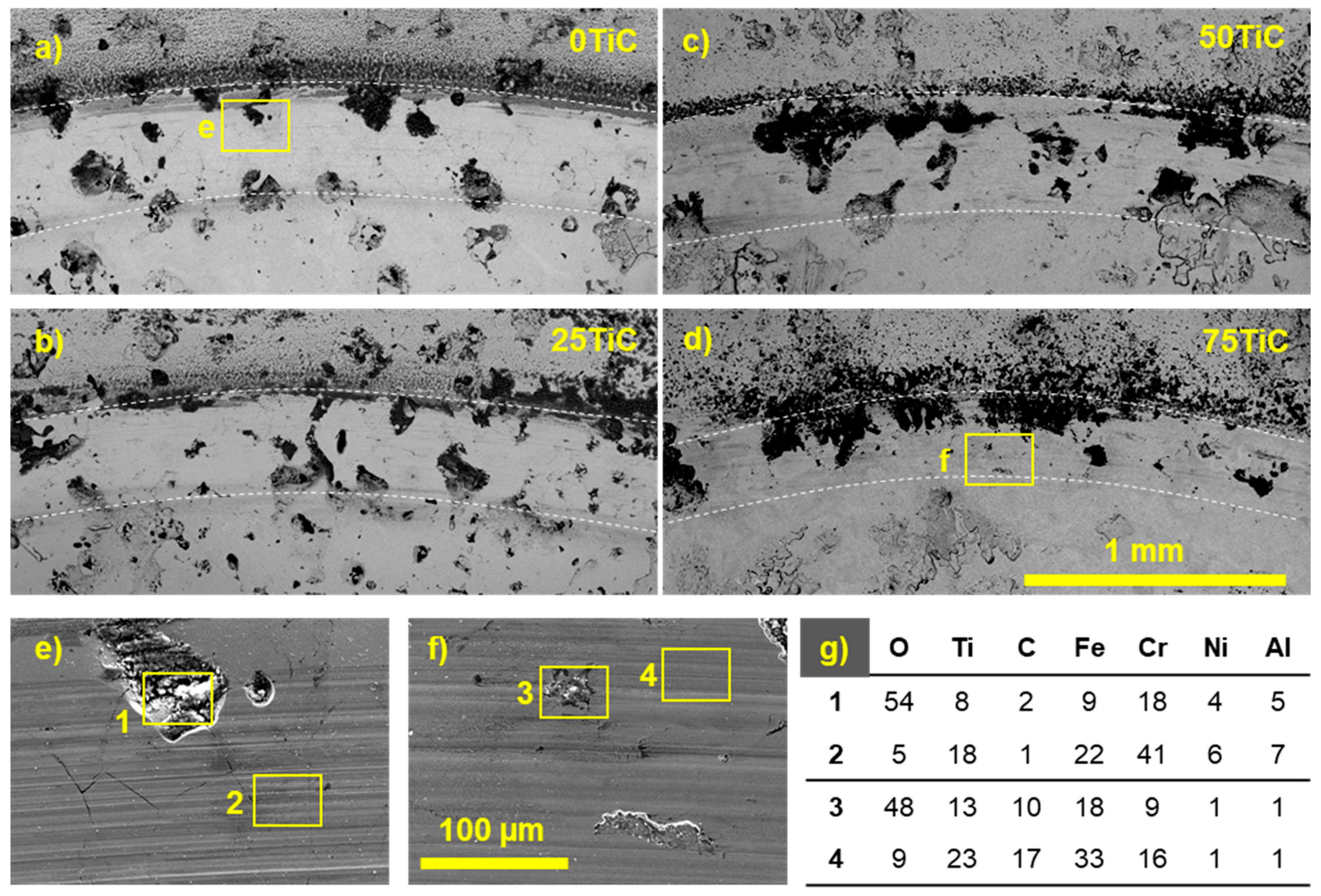
3.2.1. SEM
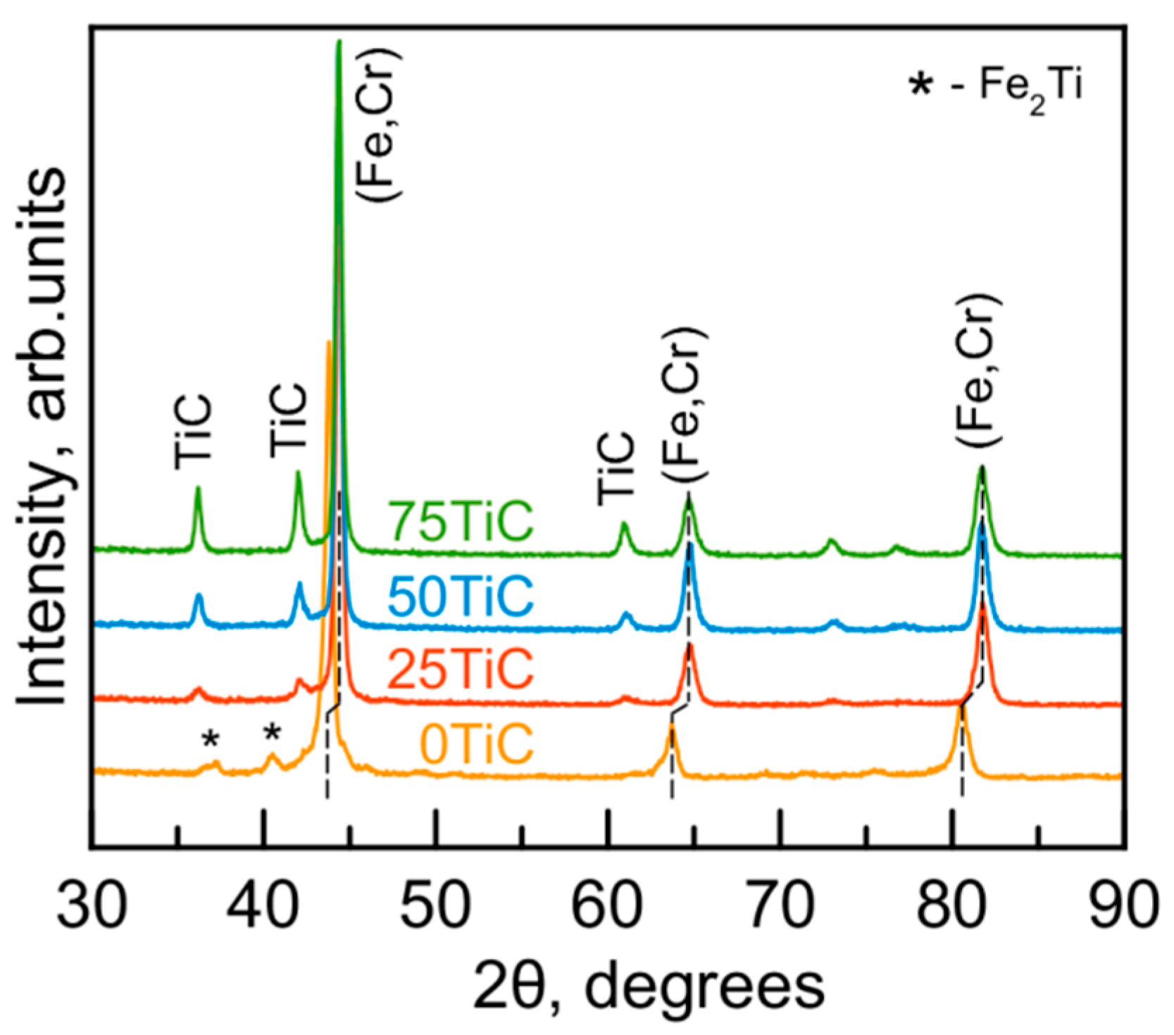
3.2.2. XRD
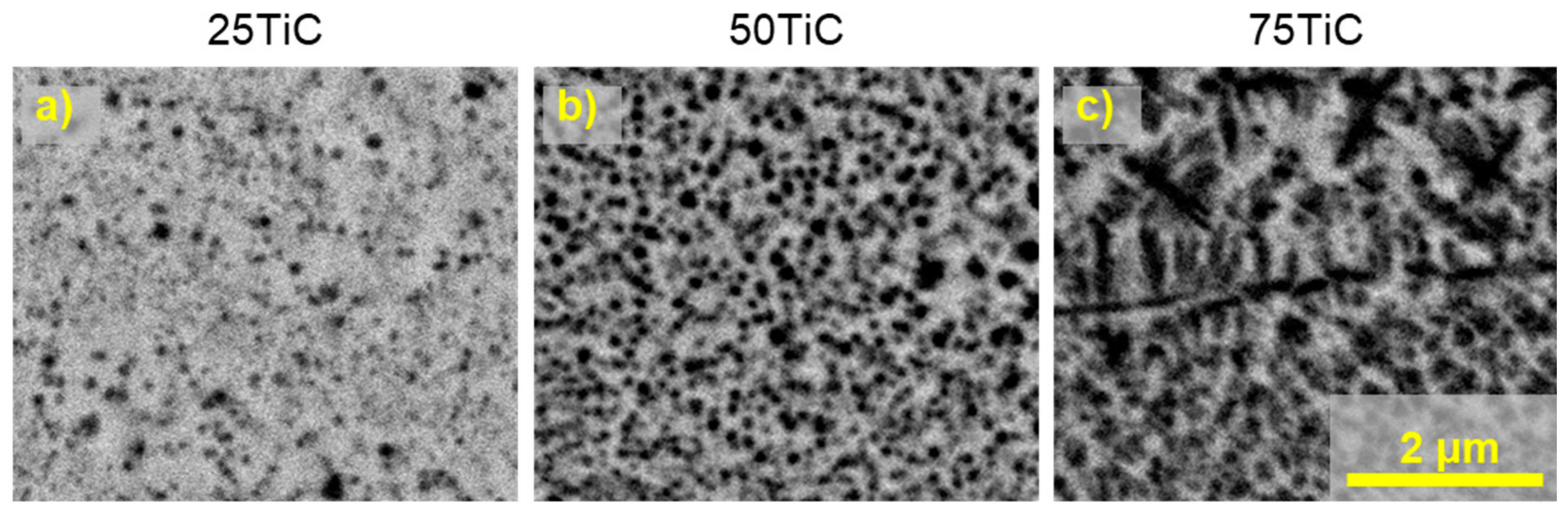
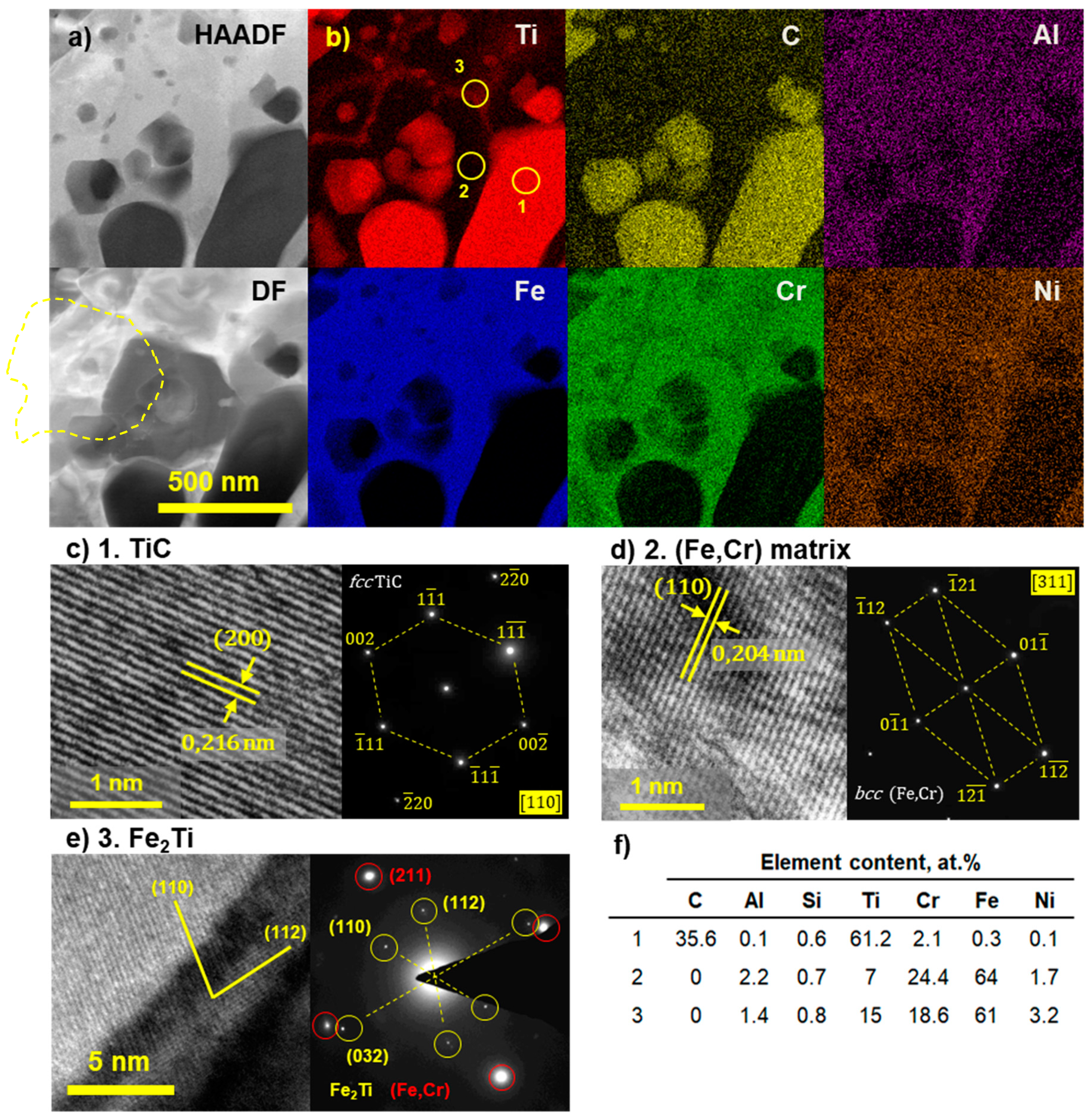
3.2.3. TEM
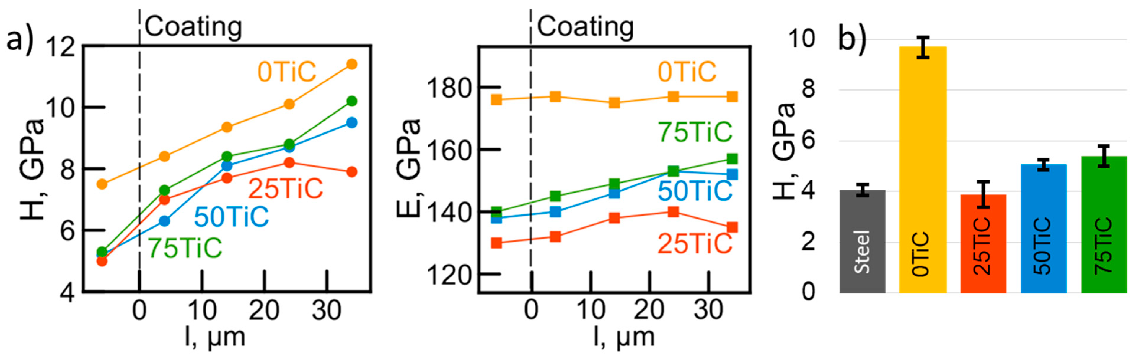
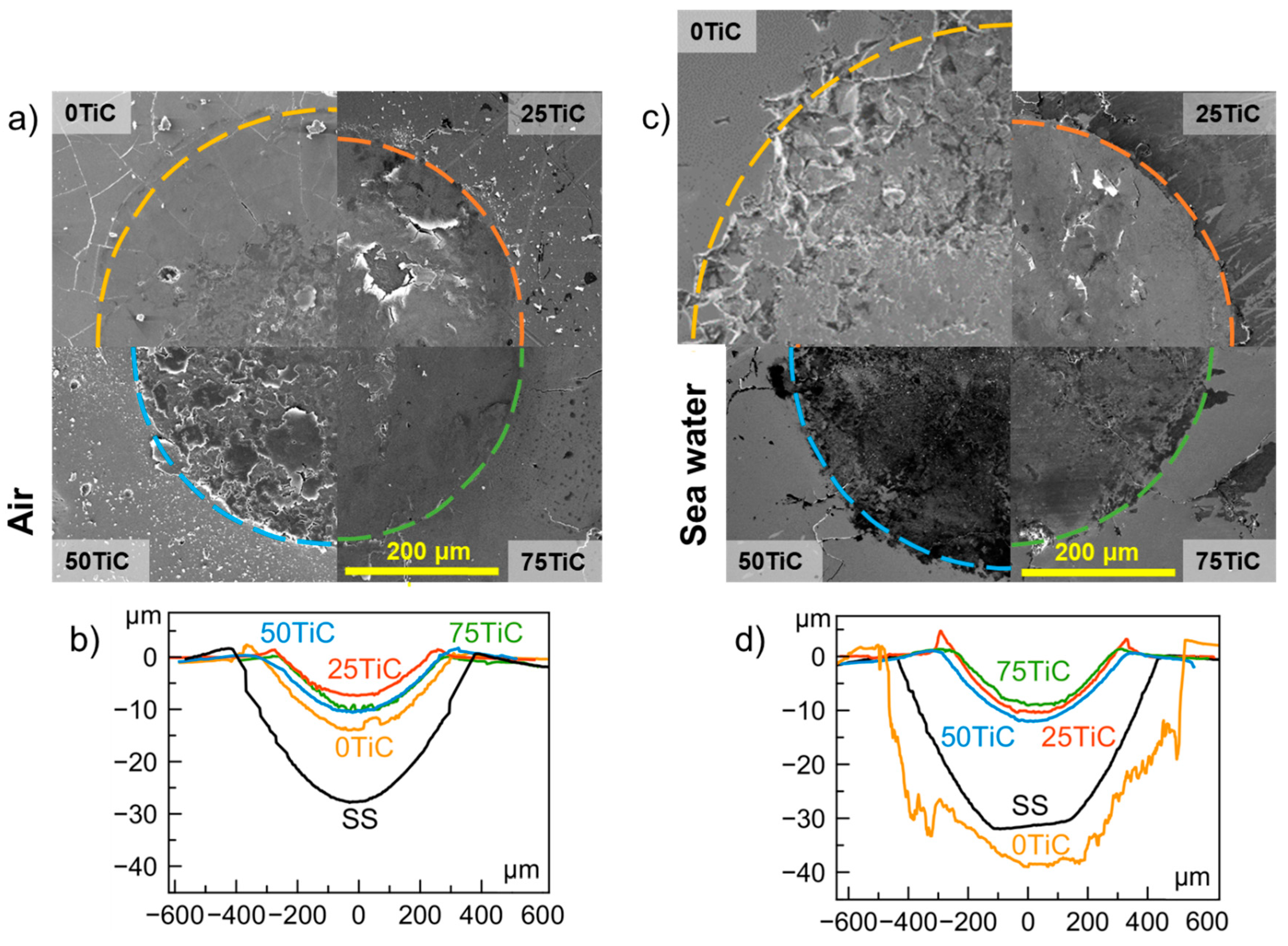
3.3. Mechanical Properties
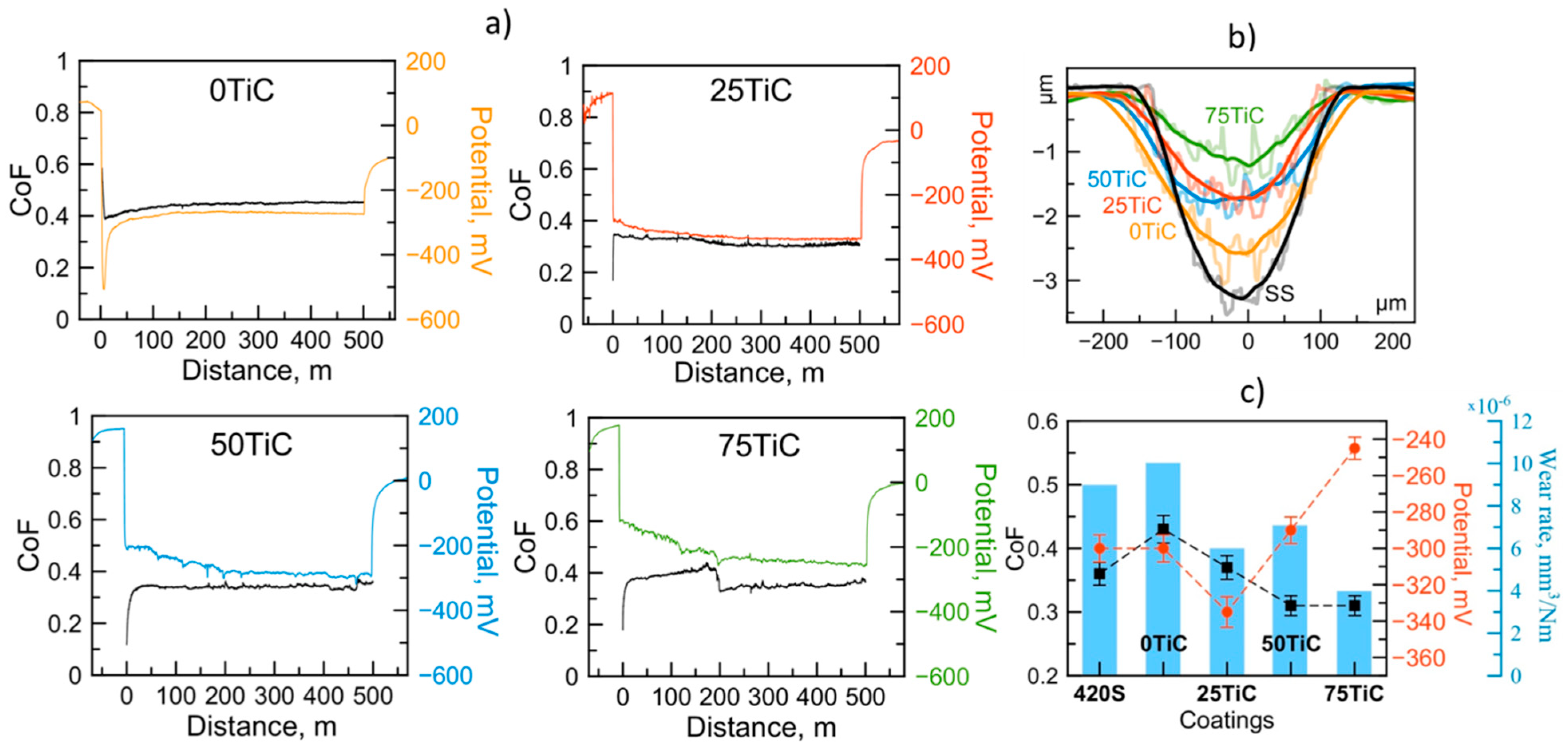
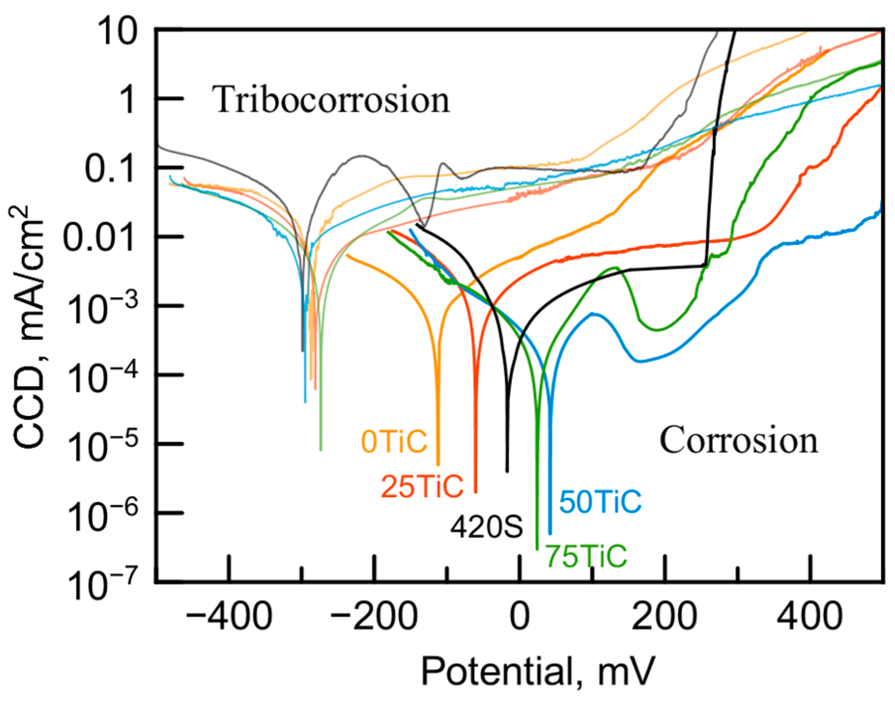
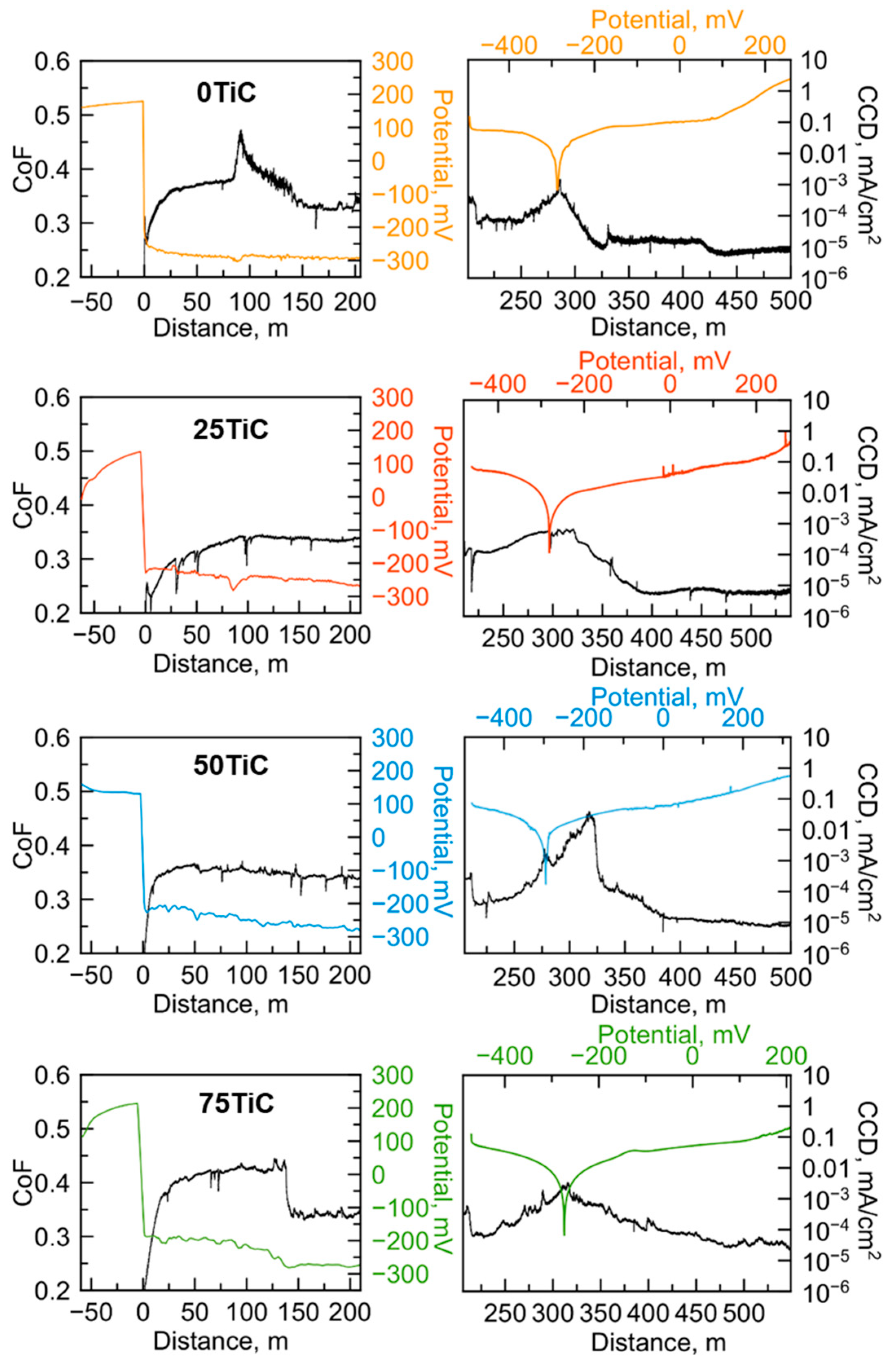
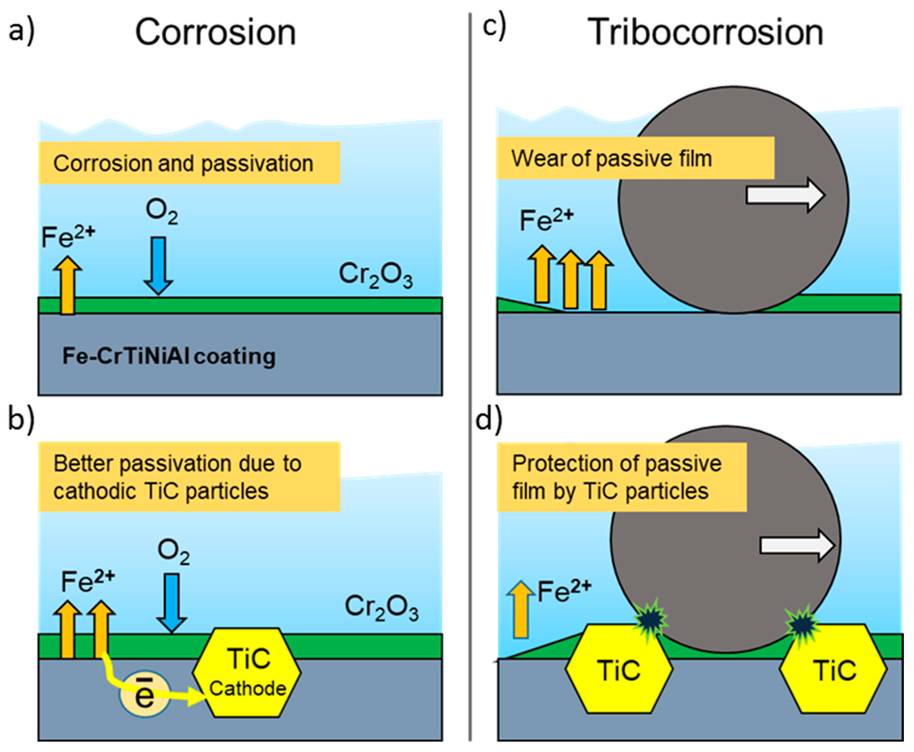
3.4. Tribocorrosion and Electrochemical Behavior of Coatings in ASW
4. Conclusions
Author Contributions
Funding
Institutional Review Board Statement
Informed Consent Statement
Data Availability Statement
Acknowledgments
Conflicts of Interest
Abbreviations
| CCD | Corrosion current density |
| OCP | Open-circuit corrosion potential |
| CoF | Coefficient of friction |
| ESD | Electrospark deposition |
| ASW | Artificial seawater |
| XRD | X-ray diffraction |
| SEM | Scanning electron microscopy |
| TEM | Transmitting electron microscopy |
| HAADF | High-angle annular dark field |
| EDS | Energy dispersive X-ray spectroscopy |
| SAED | Selected area electron diffraction |
| HR | TEM high resolution transmitting electron microscopy |
| DF | Dark field |
References
- Castro, J.D.; Lima, M.J.; Carvalho, S. Corrosion Resistance of Cu-Zr(O) N Films in a Simulated Seawater Environment. Surf. Coat. Technol. 2022, 451, 129050. [Google Scholar] [CrossRef]
- Liu, W.; Yang, H.; Li, X.; Zhang, Z.; Lin, Y.; Deng, K. Effect of Chloride and Iodide on the Corrosion Behavior of 13Cr Stainless Steel. Metals 2022, 12, 1833. [Google Scholar] [CrossRef]
- Olsson, C.O.A.; Landolt, D. Passive Films on Stainless Steels—Chemistry, Structure and Growth. Electrochim. Acta 2003, 48, 1093–1104. [Google Scholar] [CrossRef]
- Wood, R.J.K. Marine Wear and Tribocorrosion. Wear 2017, 376–377, 893–910. [Google Scholar] [CrossRef]
- Hoque, M.A.; Yao, C.W.; Khanal, M.; Lian, I. Tribocorrosion Behavior of Micro/Nanoscale Surface Coatings. Sensors 2022, 22, 9974. [Google Scholar] [CrossRef]
- Rocha, A.M.F.; Bastos, A.C.; Cardoso, J.P.; Rodrigues, F.; Fernandes, C.M.; Soares, E.; Sacramento, J.; Senos, A.M.R.; Ferreira, M.G.S. Corrosion Behaviour of WC Hardmetals with Nickel-Based Binders. Corros. Sci. 2019, 147, 384–393. [Google Scholar] [CrossRef]
- Alizadeh, M.; Mohammadi, G. Effect of Micro-Alloying Chromium on the Corrosion Resistance of Nanocrystalline Nickel Aluminide Intermetallic Produced by Mechanical Alloying Process. Mater. Lett. 2012, 67, 148–150. [Google Scholar] [CrossRef]
- Cihangir, S.; Say, Y.; Ozkul, İ.; Guler, O.; Guler, S.H. Microstructure and Corrosion Investigation of FeCoCrNiMo0,5(MnAl)0,3 High Entropy Alloy Produced by 316 L Stainless Steel Scrap. Mater. Today Commun. 2022, 33, 104360. [Google Scholar] [CrossRef]
- Lin, C.; Wu, W.; Han, Y.; Liu, J.; Zhang, M.; Wang, Q.; Li, X. Orderly Nucleation and Competitive Growth Behaviors of Ti-Al Intermetallic Compounds in Ti/TiAl3 Diffusion Couple under High Temperature. J. Alloy. Compd. 2023, 939, 168815. [Google Scholar] [CrossRef]
- Singh, A.P.; Srivastava, C. Understanding the Non-Monotonic Variation in the Corrosion Rate of Sn-Ni Coatings with Ni Addition by the Analysis of Texture and Grain Boundary Constitution of the Matrix Phase and Spatial Distribution of the Intermetallic Phase in the Coating Microstructure. Corros. Sci. 2023, 211, 110787. [Google Scholar] [CrossRef]
- Cai, C.; Song, B.; Wei, Q.; Xue, P.; Wen, S.; Liu, J.; Shi, Y. In-Situ Integrated Fabrication of Ti–Ni Coating during Hot Isostatic Pressing of Ti6Al4V Parts: Microstructure and Tribological Behavior. Surf. Coat. Technol. 2015, 280, 194–200. [Google Scholar] [CrossRef]
- Chen, Y.; Niu, H.; Kong, F.; Xiao, S. Microstructure and Fracture Toughness of a β Phase Containing TiAl Alloy. Intermetallics 2011, 19, 1405–1410. [Google Scholar] [CrossRef]
- Yokoshima, S.; Yamaguchi, M. Fracture Behavior and Toughness of PST Crystals of TiAl. Acta Mater. 1996, 44, 873–883. [Google Scholar] [CrossRef]
- Ahledel, N.; Schulz, R.; Gariepy, M.; Hermawan, H.; Alamdari, H. Electrochemical Corrosion Behavior of Fe3Al/TiC and Fe3Al-Cr/TiC Coatings Prepared by HVOF in NaCl Solution. Metals 2019, 9, 437. [Google Scholar] [CrossRef]
- Bin Humam, S.; Gyawali, G.; Amanov, A.; Kim, T.H.; Lee, S.W. Microstructure, Interface, and Nanostructured Surface Modifications to Improve Mechanical and Tribological Performance of Electrodeposited Ni-W-TaC Composite Coating. Surf. Coat. Technol. 2021, 419, 127293. [Google Scholar] [CrossRef]
- Wang, Q.; Luo, S.; Wang, S.; Wang, H.; Ramachandran, C.S. Wear, Erosion and Corrosion Resistance of HVOF-Sprayed WC and Cr3C2 Based Coatings for Electrolytic Hard Chrome Replacement. Int. J. Refract. Met. Hard Mater. 2019, 81, 242–252. [Google Scholar] [CrossRef]
- Santaella-González, J.B.; Hernández-Torres, J.; Morales-Hernández, J.; Flores-Ramírez, N.; Ferreira-Palma, C.; Rodríguez-Jiménez, R.C.; García-González, L. Effect of the Number of Bilayers in Ti/TiN Coatings on AISI 316L Deposited by Sputtering on Their Hardness, Adhesion, and Wear. Mater. Lett. 2022, 316, 132037. [Google Scholar] [CrossRef]
- Fang, J.; Piliptsou, D.G.; Bekarevich, R.; Rogachev, A.V.; Jiang, X.; Kulesh, E. Effect of the Alloying Elements in TiN Sublayer on the Structure and Mechanical Properties of Carbon Coatings. Thin Solid Films 2022, 755, 139324. [Google Scholar] [CrossRef]
- Ou, Y.X.; Wang, H.Q.; Hua, Q.S.; Liao, B.; Ouyang, X.P. Tribocorrosion Behaviors of Superhard yet Tough Ti-C-N Ceramic Coatings. Surf. Coat. Technol. 2022, 439, 128448. [Google Scholar] [CrossRef]
- Zou, Y.; Tan, C.; Qiu, Z.; Ma, W.; Kuang, M.; Zeng, D. Additively Manufactured SiC-Reinforced Stainless Steel with Excellent Strength and Wear Resistance. Addit. Manuf. 2021, 41, 101971. [Google Scholar] [CrossRef]
- Kan, W.H.; Proust, G.; Bhatia, V.; Chang, L.; Dolman, K.; Lucey, T.; Tang, X.; Cairney, J. Slurry Erosion, Sliding Wear and Corrosion Behavior of Martensitic Stainless Steel Composites Reinforced in-Situ with NbC Particles. Wear 2019, 420–421, 149–162. [Google Scholar] [CrossRef]
- Wang, X.; Wang, M.; Yi, H.; García, J.L.; Wang, X.; Wang, M. Research on the Preparation Process and Performance of a Wear-Resistant and Corrosion-Resistant Coating. Crystals 2022, 12, 591. [Google Scholar] [CrossRef]
- Antonyuk, M.N.; Kuptsov, K.A.; Sheveyko, A.N.; Shtansky, D.V. Antibacterial TaC-(Fe,Cr,Mo,Ni)-(Ag/Cu) Composite Coatings with High Wear and Corrosion Resistance in Artificial Seawater. Lubricants 2022, 10, 320. [Google Scholar] [CrossRef]
- Wu, T.; Chen, Y.; Lin, B.; Yu, L.; Gui, W.; Li, J.; Wu, Y.; Zeng, D. Effects of WC on the Microstructure, Wear and Corrosion Resistance of Laser-Deposited CoCrFeNi High Entropy Alloy Coatings. Coatings 2022, 12, 985. [Google Scholar] [CrossRef]
- Li, W.; Li, J.; Xu, Y. Investigation into the Corrosion Wear Resistance of CoCrFeNiAlx Laser-Clad Coatings Mixed with the Substrate. Metals 2022, 12, 460. [Google Scholar] [CrossRef]
- Tang, M.; Zhang, L.; Zhang, N. Microstructural Evolution, Mechanical and Tribological Properties of TiC/Ti6Al4V Composites with Unique Microstructure Prepared by SLM. Mater. Sci. Eng. A 2021, 814, 141187. [Google Scholar] [CrossRef]
- Günen, A.; Soylu, B.; Karakaş, Ö. Titanium Carbide Coating to Improve Surface Characteristic, Wear and Corrosion Resistance of Spheroidal Graphite Cast Irons. Surf. Coat. Technol. 2022, 437, 128280. [Google Scholar] [CrossRef]
- Kayalı, Y.; Kanca, E.; Günen, A. Effect of Boronizing on Microstructure, High-Temperature Wear and Corrosion Behavior of Additive Manufactured Inconel 718. Mater. Charact. 2022, 191, 112155. [Google Scholar] [CrossRef]
- Siddiqui, A.R.; Maurya, R.; Katiyar, P.K.; Balani, K. Superhydrophobic, Self-Cleaning Carbon Nanofiber CVD Coating for Corrosion Protection of AISI 1020 Steel and AZ31 Magnesium Alloys. Surf. Coat. Technol. 2020, 404, 126421. [Google Scholar] [CrossRef]
- Liao, L.; Gao, R.; Yang, Z.H.; Wu, S.T.; Wan, Q. A Study on the Wear and Corrosion Resistance of High-Entropy Alloy Treated with Laser Shock Peening and PVD Coating. Surf. Coat. Technol. 2022, 437, 128281. [Google Scholar] [CrossRef]
- Feng, J.; Xiao, H. Tribocorrosion Behavior of Laser Cladded Ti-Al-(C, N) Composite Coatings in Artificial Seawater. Coatings 2022, 12, 187. [Google Scholar] [CrossRef]
- Aubry, P.; Blanc, C.; Demirci, I.; Gorny, C.; Maskrot, H. Analysis of a Ni-Fe-Cr-Mo-Si Hardfacing Alloy Manufactured by Laser Cladding: Influence of the Iron Content on the Wear Resistance Properties. Procedia CIRP 2018, 74, 210–213. [Google Scholar] [CrossRef]
- Brezinová, J.; Landová, M.; Guzanová, A.; Dulebová, L.; Draganovská, D. Microstructure, Wear Behavior and Corrosion Resistance of WC-FeCrAl and WC-WB-Co Coatings. Metals 2018, 8, 399. [Google Scholar] [CrossRef]
- Klekotka, M.; Zielińska, K.; Stankiewicz, A.; Kuciej, M. Tribological and Anticorrosion Performance of Electroplated Zinc Based Nanocomposite Coatings. Coatings 2020, 10, 594. [Google Scholar] [CrossRef]
- Kuptsov, K.A.; Kiryukhantsev-Korneev, P.V.; Sheveyko, A.N.; Shtansky, D.V. Comparative Study of Electrochemical and Impact Wear Behavior of TiCN, TiSiCN, TiCrSiCN, and TiAlSiCN Coatings. Surf. Coat. Technol. 2013, 216, 273–281. [Google Scholar] [CrossRef]
- Kuptsov, K.A.; Sheveyko, A.N.; Manakova, O.S.; Sidorenko, D.A.; Shtansky, D.V. Comparative Investigation of Single-Layer and Multilayer Nb-Doped TiC Coatings Deposited by Pulsed Vacuum Deposition Techniques. Surf. Coat. Technol. 2020, 385, 125422. [Google Scholar] [CrossRef]
- Kuptsov, K.A.; Sheveyko, A.N.; Zamulaeva, E.I.; Sidorenko, D.A.; Shtansky, D.V. Two-Layer Nanocomposite WC/a-C Coatings Produced by a Combination of Pulsed Arc Evaporation and Electro-Spark Deposition in Vacuum. Mater. Des. 2019, 167, 107645. [Google Scholar] [CrossRef]
- Kuptsov, K.A.; Sheveyko, A.N.; Sidorenko, D.A.; Shtansky, D.V. Electro-Spark Deposition in Vacuum Using Graphite Electrode at Different Electrode Polarities: Peculiarities of Microstructure, Electrochemical and Tribological Properties. Appl. Surf. Sci. 2021, 566, 150722. [Google Scholar] [CrossRef]
- Pezzato, L.; Vranescu, D.; Sinico, M.; Gennari, C.; Settimi, A.G.; Pranovi, P.; Brunelli, K.; Dabalà, M. Tribocorrosion Properties of PEO Coatings Produced on AZ91 Magnesium Alloy with Silicate- or Phosphate-Based Electrolytes. Coatings 2018, 8, 202. [Google Scholar] [CrossRef]
- Petrov, Y.I.; Shafranovsky, E.A.; Krupyanskii, Y.F.; Essine, S.V. Structure and Mössbauer Spectra for the Fe–Cr System: From Bulk Alloy to Nanoparticles. J. Appl. Phys. 2001, 91, 352. [Google Scholar] [CrossRef]
- Tornabene, F.; Lu, C.-J.; Yeh, J.-W. Improved Wear and Corrosion Resistance in TiC-Reinforced SUS304 Stainless Steel. J. Compos. Sci. 2023, 7, 34. [Google Scholar] [CrossRef]
- Sheveyko, A.N.; Kuptsov, K.A.; Kiryukhantsev-Korneev, P.V.; Kaplansky, Y.Y.; Orekhov, A.S.; Levashov, E.A. Protective Coatings for LPBF Ni-Based Superalloys Using a Combination of Electrospark Deposition and Pulsed Arc Evaporation Methods. Appl. Surf. Sci. 2022, 581, 152357. [Google Scholar] [CrossRef]
- Zhang, J.; Xin, S.; Zhang, Y.; Guo, P.; Sun, H.; Li, T.; Qin, C. Effects of Elements on the Microstructure and Mechanical Properties of AlCoCrFeNiTi High-Entropy Alloys. Metals 2023, 13, 178. [Google Scholar] [CrossRef]
- Memarrashidi, Z.; Plucknett, K.P. The Effects of C:N Ratio on the Aqueous Corrosion Response of TiC and Ti(C,N) Cermets with a Ni3Al-Based Binder. Int. J. Refract. Met. Hard Mater. 2016, 61, 162–172. [Google Scholar] [CrossRef]


| - | C | Ti | Cr | Fe | Ni | Al |
|---|---|---|---|---|---|---|
| 0TiC | - | 18 | 39 | 20 | 11 | 12 |
| 25TiC | 5 | 11 | 23 | 58 | 1 | 2 |
| 50TiC | 9 | 20 | 21 | 47 | 1 | 2 |
| 75TiC | 14 | 22 | 17 | 45 | 1 | 1 |
| - | Corrosion | Tribocorrosion | ||
|---|---|---|---|---|
| Material | Ecorr, mV | CCD, µA/cm2 | Ecorr, mV | CCD, µA/cm2 |
| Substrate | −25 ± 3 | 0.41 ± 0.06 | −300 ± 26 | 22 ± 3 |
| 0TiC | −110 ± 6 | 0.22 ± 0.05 | −288 ± 17 | 9 ± 1 |
| 25TiC | −62 ± 7 | 0.05 ± 0.02 | −300 ± 17 | 6.2 ± 1 |
| 50TiC | 42 ± 5 | 0.05 ± 0.02 | −282 ± 16 | 4 ± 0.3 |
| 75TiC | 24 ± 4 | 0.03 ± 0.01 | −276 ± 9 | 0.8 ± 0.1 |
| Material | In Air | In ASW | ||
|---|---|---|---|---|
| R, µm | h, µm | R, µm | h, µm | |
| Substrate | 400 | 28 | 430 | 31 |
| 0TiC | 330 | 15 | 500 | 39 |
| 25TiC | 300 | 13 | 310 | 12 |
| 50TiC | 320 | 10 | 310 | 12 |
| 75TiC | 270 | 10 | 290 | 8 |
Disclaimer/Publisher’s Note: The statements, opinions and data contained in all publications are solely those of the individual author(s) and contributor(s) and not of MDPI and/or the editor(s). MDPI and/or the editor(s) disclaim responsibility for any injury to people or property resulting from any ideas, methods, instructions or products referred to in the content. |
© 2023 by the authors. Licensee MDPI, Basel, Switzerland. This article is an open access article distributed under the terms and conditions of the Creative Commons Attribution (CC BY) license (https://creativecommons.org/licenses/by/4.0/).
Share and Cite
Kuptsov, K.A.; Antonyuk, M.N.; Sheveyko, A.N.; Bondarev, A.V.; Shtansky, D.V. Influence of TiC Addition on Corrosion and Tribocorrosion Resistance of Cr2Ti-NiAl Electrospark Coatings. Coatings 2023, 13, 469. https://doi.org/10.3390/coatings13020469
Kuptsov KA, Antonyuk MN, Sheveyko AN, Bondarev AV, Shtansky DV. Influence of TiC Addition on Corrosion and Tribocorrosion Resistance of Cr2Ti-NiAl Electrospark Coatings. Coatings. 2023; 13(2):469. https://doi.org/10.3390/coatings13020469
Chicago/Turabian StyleKuptsov, Konstantin A., Mariya N. Antonyuk, Alexander N. Sheveyko, Andrey V. Bondarev, and Dmitry V. Shtansky. 2023. "Influence of TiC Addition on Corrosion and Tribocorrosion Resistance of Cr2Ti-NiAl Electrospark Coatings" Coatings 13, no. 2: 469. https://doi.org/10.3390/coatings13020469
APA StyleKuptsov, K. A., Antonyuk, M. N., Sheveyko, A. N., Bondarev, A. V., & Shtansky, D. V. (2023). Influence of TiC Addition on Corrosion and Tribocorrosion Resistance of Cr2Ti-NiAl Electrospark Coatings. Coatings, 13(2), 469. https://doi.org/10.3390/coatings13020469