Article

The Study of Surface Structure and the Tribological Property of DLC-Modified NBR Elastomers Using DC-MS

1
Special Glass Key Laboratory of Hainan Province, Hainan University, Haikou 570228, China
2
School of Materials Science and Engineering, Hainan University, Haikou 570228, China
3
School of Science, Hainan University, Haikou 570228, China
*
Authors to whom correspondence should be addressed.
Coatings 2023, 13(2), 468; https://doi.org/10.3390/coatings13020468
Submission received: 29 December 2022 / Revised: 19 January 2023 / Accepted: 15 February 2023 / Published: 18 February 2023

Abstract

:
The DLC film was prepared on a nitrile rubber (NBR) elastomer by DC magnetron sputtering (DC-MS), and the sp3 ratio of the DLC film was adjusted by changing the negative bias voltage applied to the substrate. The microstructure, composition, and tribological properties of the DLC films deposited on NBR substrates were systematically investigated. The results reveal that the DLC film on the NBR surface can protect the NBR and reduce the surface roughness of the NBR. While the bias voltage ranges from 0 V to −150 V, the content of sp3 increases with an increase in the negative bias voltage. The viscoelasticity and roughness of the NBR substrate will greatly affect the DLC film’s adhesion strength and tribological behavior.

1. Introduction

Most working conditions of rubber sealing products are in a dynamic sliding state. Cutting down the friction coefficient of rubber can effectively reduce friction and decrease the wear of rubber products, thus prolonging their service life [1,2].
At present, lubrication and coatings are usually used for rubber sealing products to reduce the friction between the sealing ring and the workpiece [3,4]. Lubricating oil, or lubricant, is mainly used for lubrication. Although convenient, lubricating mediums will cause failure due to degradation during use and lead to the problem of environmental pollution [5]. Thus, low-wear and pollution-free non-lubricating seal coatings have been widely emphasized and studied [6,7].
Diamond-like carbon (DLC) film is a kind of amorphous carbon film with good gas and liquid barrier effects, high wear resistance, favorable chemical stability, and a low friction coefficient [8,9,10,11]. DLC can be deposited on various types of matrix materials, such as alloys, stainless steel, glass, etc., and can provide corking mechanical protection [12,13,14]. However, there are few studies that apply it to the rubber field, and this is mainly due to the large difference in hardness between DLC and nitrile rubber (NBR) [15]. The hardness of DLC films is mostly 15–60 GPa, putting it in the category of hard films [16,17]. However, the Shore A hardness of NBR elastomers is generally about 70 [18,19]. The hardness of NBR, which belongs to flexible materials, is much lower than that of DLC. When subjected to external force, comparing the deformations produced by DLC and NBR is difficult, resulting in coating invalidation. Liu et al. [20] evaluated the corresponding hardness values by preparing a thin film on a silicon wafer substrate, identical to the surface of the NBR, as a reference. The variation trend of DLC on the surface of NBR was determined by the variation trend of the hardness value of DLC on the surface of the silicon wafer. However, this method still cannot fundamentally solve the deformation mismatch problem. Although Bai et al. [12] adopted the same method to judge the hardness of DLC films on the NBR surface, they further proposed that the roughness, adhesion strength, bearing capacity of DLC, and graphitization lubrication also affect the tribological behavior. Xu et al. [21] determined the adhesion strength of the DLC films by examining crack propagation and incision morphologies via the bending and X-cutting of the sample, but it is impossible to quantitatively analyze the adhesion strength of the coating.
In this paper, the series of DLC films deposited on the NBR elastomer surface was synthesized by changing the bias voltage of the substrate (the bias voltages in this paper are all negative bias voltages, and the increase in the bias voltage means that the magnitude of the absolute value is increasing: hereinafter referred to as bias voltage). The tribological behavior of the NBR coated with DLC coatings under different bias voltages was studied. The purpose is to study the protective effect of DLC coatings on NBR.

2. Materials and Methods

2.1. Preparation of DLC Films

The NBR (30 mm × 30 mm × 6 mm) was cleaned with ethanol and boiling water in turn for 10 min so that the residual grease and impurities on the NBR could be removed [22]. After the cleaning step was cycled 4 times, a vacuum oven was used to dry the NBR at 100 °C for 2 h. It should be noted that during the ethanol cleaning process, the ethanol changed from colorless to yellow. With the increase in cleaning times, the yellow color gradually became lighter until it disappeared, as shown in Figure 1. This is due to the extraction of additives, antioxidants, oligomers, and other components in NBR [23].
While the NBR substrates were placed in a chamber before the preparation of the DLC film on the NBR, the NBR substrate was further cleaned by Ar+ sputtering to remove surface impurities and oxide layers [24]. Under the pressure of 1.5 Pa and the power of 50 W, the graphite target was sputtered and cleaned by magnetron sputtering technology. It is worth noting that while cleaning the target, the sample shutter should be closed to prevent the sputtered graphite oxide layer from contaminating the cleaned NBR substrate.
At the beginning of the preparation, the initial pressure was controlled at 2 Pa and four pulse bias voltages (duty cycle of 75% and the frequency of 40 kHz) of 0 V, −50 V, −100 V, and −150 V, named sample-0, sample-50, sample-100, and sample-150, respectively, were used to synthesize series DLC films on the NBR. During the entire process, the direct current (DC) sputtering power was maintained at 100 W, and the deposition time of each DLC film was 10 min.

2.2. Material Characterization

A scanning electron microscope (SEM) and an atomic force microscope (AFM) were used to observe the surface morphology of DLC-coated NBR and uncoated NBR elastomer substrates. The bonding structure and composition of the DLC films were analyzed by Raman spectroscopy (514 nm) and X-ray photoelectron spectroscopy (XPS, monochromatic Al Kα radiation). The adhesion of the coatings was tested by a nano-scratching tester, automatically and continuously loaded in the range of 2–100 mN within 1.5 mm, and the scratch speed was 0.02 mm/s. The coefficient of friction (COF) was measured by a reciprocating friction tester with a 2 mN load and 10 mm friction trace length. The friction speed and the numbers of reciprocating friction were set to 1 mm/s and 40 times, respectively.

3. Results and Discussion

3.1. Surface Topography

Figure 2 shows SEM pictures of the as-prepared samples. It can be seen in Figure 2 that the surface of NBR has both convex and concave structures, and this is because the NBR substrate itself has more additive particles and surface damage, which is due to the injection molding process of NBR and the additive ZnO particles [21,22,23]. The subsequent XPS analysis can confirm this. However, after being covered with a layer of DLC coating, the surface of the NBR is relatively flat compared with the uncoated NBR surface. Since the DLC film did not fill the ravines well, even when the surface of NBR was coated with DLC film, a large number of voids and bulk particles were still observed on the surface of NBR in Figure 2a–d. Additionally, the surface of sample-100 is rougher than that of the other samples.
Figure 3a–e show the AFM images and 3D morphology of NBR and DLC films prepared on the NBR substrates, as well as the change curve of surface roughness (Figure 3f). During the AFM test, a mechanical probe was used to scan the surface of the sample, and the collected surface profile information is presented in a photo with a different color. Generally, all samples indicate a roughness of no less than 350 nm for Sa and 500 nm for Sq. The reason is, on the one hand, the surface of NBR itself is uneven, as shown in Figure 3e, and the defects on the surface of the NBR substrate cannot be filled effectively as the DLC film is not thick enough. On the other hand, the roughness is due to the island-like growths of the DLC film on the rubber surface. However, the roughness curve shows that the roughness of the NBR decreased after coating the DLC film onto the NBR substrate, which was also supported by the SEM photos. In addition, the roughness of sample-0 is higher than that of the other samples. In a word, the roughness of the samples demonstrates a downward trend, and the surface becomes smoother, which may be due to the better diffusion and growth effect of carbon ions on the rubber substrate surface under certain incident energy. Moreover, in the case of thinner films, the surface defects of the NBR substrate also have a greater impact on the surface roughness of the samples [25].

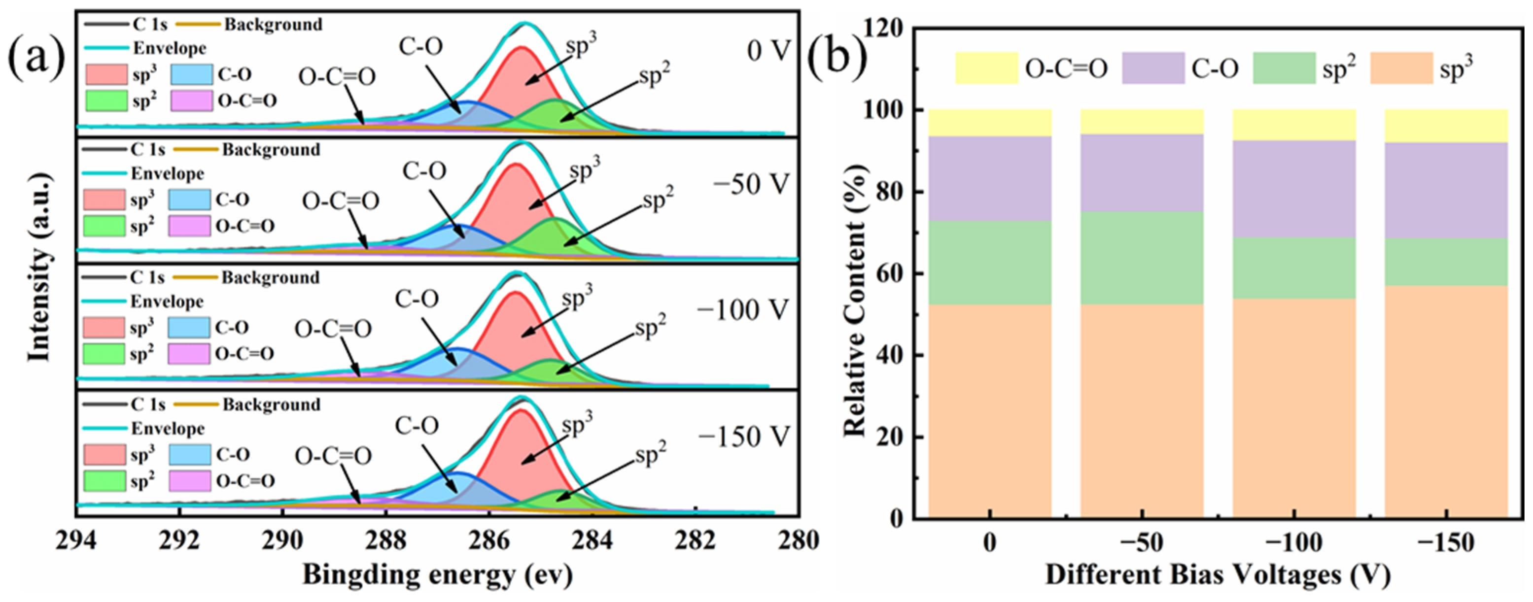
3.2. Structure and Composition

Figure 4 shows the Raman spectra of the DLC-coated NBR samples. For single-crystal graphite, there is a single Raman peak around 1580 cm−1, which is generated by the central vibration mode of the E2g region allowed by the crystalline graphite optics. It is a symbol of the existence of sp2 C-C hybrid bonds, and it is called the G peak [16,26,27]. For diamond, the characteristic Raman peak is located at 1322 cm−1, which is derived from the T2g symmetrical vibration mode, and it is a sign of the existence of sp3 C-C hybrid bonds. When the long-range order is broken, a peak will appear around 1360 cm−1, which is caused by the dissipation of the Brillouin zone boundary phonon, which becomes the D peak [28,29,30]. The appearance of the D peak expresses the disorder of the sp2 hybrid bond angle, which is a sign that the sp2 hybrid carbon is composed of a graphite ring. In Figure 4, an obvious peak can be seen in all samples. In addition, a new peak appeared around 1415 cm−1, which was caused by the aromatic substituents in NBR [4]. In the process of sputtering, the temperature in the vacuum chamber was basically at room temperature in the beginning and no more than 120 °C during the entire sputtering process, which was much lower than the temperature (295 °C) when NBR began to degrade [31]. However, when carbon plasma bombards the surface of NBR, the polymer chain may be randomly broken to produce a large number of active groups, and these active groups react with each other or overflow the surface to react with carbon, forming complex cross-linked structures. It is also possible for carbon to react with an unpaired sp2 bond in NBR to form a six-fold ring that minimizes the internal energy [32,33]. Generally speaking, the Raman spectrum of the DLC film will take on an asymmetric broad peak at around 1500 cm−1 [34].
To obtain more explicit information on the carbon-bonding structure in the DLC films coated on the NBR, Gaussian fitting is used to obtain the deconvoluted Raman spectra after subtracting the baseline operation from the obtained Raman spectra. The broad peaks exhibit sub-peak fitting, and the three peaks can be obtained as shown in Figure 5.
By calculating the value of ID/IG from the peak area of the D peak and the G peak, the fraction of the sp3 hybrid is estimated qualitatively [20,35]. In general, when the ratio becomes smaller, the content of sp3 hybrid bonds increases [36]. As observed in Figure 5, when the bias voltage increases from 0 V to −150 V, ID/IG gradually decreases. Combined with the subsurface injection model, it can be seen that when the energy of the C+ incident is low, it mainly consumes energy by colliding with collective atoms, which cannot penetrate the surface and adheres to the surface of the coating. When the incident energy increases within a certain range, C+ can penetrate the surface layer, stay in the subsurface layer, and become interstitial atoms, increasing local density and compressive stress. Under the action of compressive stress, the atomic groups in the DLC tend to generate a stable phase for the sp3 hybrid bond.
Figure 6 was obtained by further calculating the fraction of each sub-peak area in light of the Gaussian fitting peak. It can be observed in Figure 6 that the proportion of aromatic substituents in sample-100 (at −100 V) is relatively high, which may be due to the rough surface and the uneven coverage of the DLC film, and makes it sensitive to a 514 nm Raman excitation wavelength.
Figure 7 provides the full XPS spectra of NBR substrates and the DLC films deposited under different bias voltages. From Figure 7, we can observe that there is an obvious C 1s peak near 284.6 eV and an O 1s peak near 531.9 eV for all samples [37]. In the range of 300–500 eV, there are some small peaks, and they are Ca 2p and N 1s, which are located around 347 eV and 399 eV, respectively. In addition, the peaks in the range of 960–1030 eV are the KLL Auger shift peaks of carbon [38]. The counts of C 1s peaks are 175,369, 169,311, 238,883, 267,171 and 107,182, corresponding to sample-0, sample-50, sample-100, sample-150 and the NBR elastomer substrate, respectively, which also proves that they have a carbon film on the surface.
An in-depth analysis of the C 1s fine spectrum was carried out, and the bonding mode of C atoms was judged by the electronic bonding state [39,40]. Using the Gauss-Lorentzian function to perform the peak fitting of C 1s, four peaks can be obtained (seen in Figure 8a). The four peaks represent the four binding states of C atoms, which are the C-C sp2 bond, C-C sp3 bond, C-O bond, and O-C=O bond, corresponding to 284.6 ± 0.2 eV, 285.3 ± 0.2 eV, 286.8 ± 0.2 eV, and 288.6 ± 0.2 eV [41,42], respectively. Here, oxygen atoms mainly originate from the adsorption on the film surface, as shown in Figure 8a. Figure 8b was obtained by calculating the four peaks’ areas for each sample. It should be noted that the content of C-C sp3 bonds gradually increased from 52.60% to 57.23% with the increase in bias voltage, which is consistent with the changing trend of ID/IG.
In addition, the fine spectrum of NBR rubber was also fitted and analyzed, including elements such as C, N, O, Zn, Ca, Si, etc., as signified in Figure 9. In the C 1s fine spectrum, the peak at 284.8 eV is mainly from the C-C long chain in NBR, and 286.8 eV and 288.6 eV correspond to the C-O bond and the O-C=O bond, respectively [43]. Combined with the O 1s spectrum, these oxygen elements are also mainly derived from NBR rubber surface adsorption, and a part of O exists in CaCO3 and ZnO. Combining N 1s and Si 2p, it can be seen that these two elements mainly exist in the form of Si3N4. CaCO3, ZnO, and Si3N4 are combined with NBR rubber in the form of fillers to optimize the microstructure of the rubber.

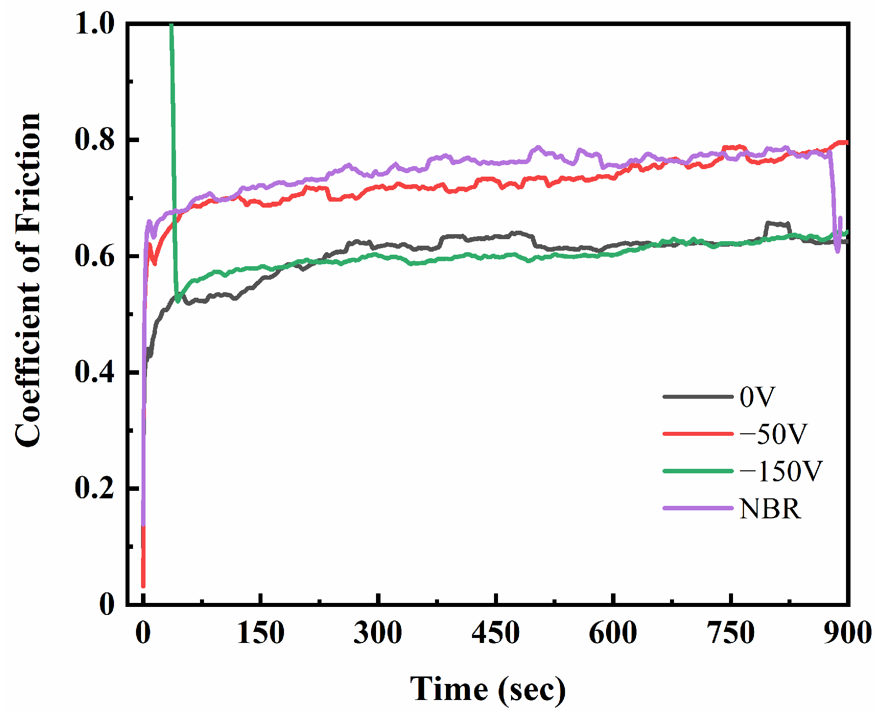
3.3. Tribology and Mechanical Properties

The DLC film deposited on the surface of NBR rubber is mainly used in the field of sealing rings. In such a dynamic working environment, the wear resistance of the material should be evaluated [44]. Figure 10 shows the friction curve of the surface-coated DLC film and the uncoated NBR rubber. As observed in Figure 10, the DLC-coated NBR exhibits a lower coefficient of friction (CoF) compared to the NBR elastomer substrate. During the ball-on-disc test, the CoF of uncoated NBR rubber was always kept at approximately 0.74. Except for the DLC-coated NBR rubber, the CoF maintained a gap of 0.02~0.15 with that of uncoated NBR rubber. Notably, sample-0 and sample-150 project the lowest CoF. Additionally, sample-0’s content of sp2 hybrid bond is high inside the DLC film based on the result of ID/IG from the Raman spectra. When the friction pair is in relative motion, the DLC film is prone to graphitization and adheres to the friction contact surface, forming a graphite lubrication layer [45]. The sp3 content in the DLC film of sample-50 increases, and hard particles are produced in the friction process, leading to an increase in CoF. When the bias voltage reaches −150 V, the sp3 content inside the coating is the highest according to its lowest value of ID/IG, thus embodying relatively better wear resistance. At the same time, it was found that the friction curve of sample-150 is the most gentle. It can be inferred that the adhesive strength is good, and no abrasive wear occurs. This assumption can be supported by subsequent scratch experiments. It can be inferred that sample-0 and sample-150 may have the best tribological properties and can play a role in protecting rubber.
The nanoscratch test was used to investigate the film–substrate adhesion. Generally speaking, the adhesive strength of the film can be judged by the acoustic signal generated during scratching. However, due to the thinner DLC coating in this experiment and a larger difference in hardness between the DLC film and the NBR’s high elasticity, no obvious acoustic signals were generated in our scratch tests for all samples, which means the critical load cannot be well determined [46]. Given the above, we can use the load at the first mutation of the friction force (Lc) to reflect the adhesion strength between the film and substrate. In the scratch test, a normal loading load (Fz) is applied to the micro-tip needle, causing it to start scratching the surface of the film, and linear loading gradually approached 100 mN. In performing this step, the magnitude of the force of friction (Fx) perpendicular to the direction of the needle’s motion is obtained. It can be observed in Figure 11 that the overall increase in Fx is accompanied by an uninterrupted mutation. This is because the viscoelasticity of the NBR elastomer substrate is much higher than that of the DLC-coated NBR elastomer. After calibration, it was found that the Lc of the sample and the changing trend of surface roughness took on an inverse relationship relative to each other, as shown in Figure 12. This is because surface defects may have a certain effect on the friction force when the needle is drawn across the surface of the sample. At the same time, the adhesion strength between the DLC film and NBR of sample-100 and sample-150 also confirmed the assumption in the friction experiment mentioned above.

4. Conclusions

In a nutshell, a series of DLC films were prepared on NBR elastomer substrates with different bias voltages by DC-MS. It was found that with the increase in bias voltage, the ID/IG of DLC film gradually decreased from 0.521 to 0.486, and the sp3 content increased from 52.60% to 57.23%, which indicates that the internal structure of DLC films can be adjusted by the bias voltage during the deposition of MS. For both the lowest or highest content of sp3 hybrid bond, the DLC film on the surface of NBR elastomer exhibits a low CoF. In the meantime, the adhesion strength of sample-150 with the highest sp3 hybrid bond is relatively high, reaching more than 20 mN. In addition, the adhesion strength of the film is inversely proportional to the roughness, which may be caused by the surface defects of the elastomer. The roughness and viscoelasticity of the NBR elastomer substrate have a great influence on the mechanical properties of DLC films, which should be further studied in the future.

Author Contributions

C.W., writing—review and editing and formal analysis; C.X., writing—original draft preparation, formal analysis, methodology, and data curation; Z.W., writing—review and editing, formal analysis, and funding acquisition; F.W., writing—original draft preparation, writing—review and editing, project administration, and funding acquisition. All authors contributed to the discussion of results and the critical reading of the manuscript. All authors have read and agreed to the published version of the manuscript.

Funding

This work was supported by the Hainan Province Science and Technology Special Fund (ZDYF2019206) and the Hainan Provincial Natural Science Foundation of China (420RC525, 518MS024).

Institutional Review Board Statement

Not applicable.

Informed Consent Statement

Not applicable.

Data Availability Statement

The data presented in this study are available upon request from the corresponding author after obtaining permission from the authorized person.

Conflicts of Interest

The authors declare no conflict of interest.

References

  1. Liu, J.; Li, X.; Xu, L.; Zhang, P. Investigation of Aging Behavior and Mechanism of Nitrile-Butadiene Rubber (NBR) in the Accelerated Thermal Aging Environment. Polym. Test. 2016, 54, 59–66. [Google Scholar] [CrossRef]
  2. Manhart, J.; Lenko, D.; Mühlbacher, I.; Hausberger, A.; Schaller, R.; Holzner, A.; Kern, W.; Schlögl, S. Photo-Patterned Natural Rubber Surfaces with Tunable Tribological Properties. Eur. Polym. J. 2015, 66, 236–246. [Google Scholar] [CrossRef]
  3. Liu, Z.; Zhou, B.; Rogachev, A.V.; Yarmolenko, M.A. Growth Feature of PTFE Coatings on Rubber Substrate by Low-Energy Electron Beam Dispersion: Growth Feature of PTFE Coatings on Rubber. Polym. Adv. Technol. 2016, 27, 823–829. [Google Scholar] [CrossRef]
  4. Zhou, Z.; Han, Y.; Qian, J. Improving Mechanical and Tribological Behaviors of GLC Films on NBR under Water Lubrication by Doping Ti and N. Coatings 2022, 12, 937. [Google Scholar] [CrossRef]
  5. Bai, C.; Liang, A.; Cao, Z.; Qiang, L.; Zhang, J. Achieving a High Adhesion and Excellent Wear Resistance Diamond-like Carbon Film Coated on NBR Rubber by Ar Plasma Pretreatment. Diam. Relat. Mater. 2018, 89, 84–93. [Google Scholar] [CrossRef]
  6. Thirumalai, S.; Hausberger, A.; Lackner, J.M.; Waldhauser, W.; Schwarz, T. Effect of the Type of Elastomeric Substrate on the Microstructural, Surface and Tribological Characteristics of Diamond-like Carbon (DLC) Coatings. Surf. Coat. Technol. 2016, 302, 244–254. [Google Scholar] [CrossRef]
  7. Martínez, D.M.; Nohava, J.; Hosson, J.T.M.D. Influence of Load on the Dry Frictional Performance of Alkyl Acrylate Copolymer Elastomers Coated with Diamond-like Carbon Films. J. Appl. Phys. 2015, 118, 175302. [Google Scholar] [CrossRef] [Green Version]
  8. Cui, L.; Zhou, H.; Zhang, K.; Lu, Z.; Wang, X. Bias Voltage Dependence of Superlubricity Lifetime of Hydrogenated Amorphous Carbon Films in High Vacuum. Tribol. Int. 2018, 117, 107–111. [Google Scholar] [CrossRef]
  9. Bhowmick, S.; Khan, M.Z.U.; Banerji, A.; Lukitsch, M.J.; Alpas, A.T. Low Friction and Wear Behaviour of Non-Hydrogenated DLC (a-C) Sliding against Fluorinated Tetrahedral Amorphous Carbon (Ta-C-F) at Elevated Temperatures. Appl. Surf. Sci. 2018, 450, 274–283. [Google Scholar] [CrossRef]
  10. Xu, W.; Lin, S.; Dai, M.; Shi, Q.; Wei, C.; Zhang, X.; Zhou, K. Effects of Bias Voltage on the Microstructure and Properties of Al-Doped Hydrogenated Amorphous Carbon Films Synthesized by a Hybrid Deposition Technique. Vacuum 2018, 154, 159–166. [Google Scholar] [CrossRef]
  11. Akaike, S.; Kobayashi, D.; Aono, Y.; Hiratsuka, M.; Hirata, A.; Hayakawa, T.; Nakamura, Y. Relationship between Static Friction and Surface Wettability of Orthodontic Brackets Coated with Diamond-like Carbon (DLC), Fluorine- or Silicone-Doped DLC Coatings. Diam. Relat. Mater. 2016, 61, 109–114. [Google Scholar] [CrossRef]
  12. Bai, C.; Qiang, L.; Zhang, B.; Gao, K.; Zhang, J. Optimizing the Tribological Performance of DLC-Coated NBR Rubber: The Role of Hydrogen in Films. Friction 2022, 10, 866–877. [Google Scholar] [CrossRef]
  13. Shen, M.; Dong, F.; Ma, Y.; Peng, J.; Zhu, M.-H. Fretting Wear Behaviors of Acrylonitrile-Butadiene Rubber (NBR) against Diamond-like Carbon and Graphene Coatings. Int. J. Adv. Manuf. Technol. 2018, 96, 1749–1759. [Google Scholar] [CrossRef]
  14. Lubwama, M.; Corcoran, B.; Sayers, K. DLC Films Deposited on Rubber Substrates: A Review. Surf. Eng. 2014, 31, 1–10. [Google Scholar] [CrossRef]
  15. Zhang, L.; Zong, X.; Guo, F.; He, B.; Yuan, X. Effect of Fluorine Incorporation on DLC Films Deposited by Pulsed Cathodic Arc Deposition on Nitrile Butadiene Rubber and Polyurethane Rubber Substrates. Coatings 2020, 10, 878. [Google Scholar] [CrossRef]
  16. Cao, H.; Qi, F.; Ouyang, X.; Zhao, N.; Zhou, Y.; Li, B.; Luo, W.; Liao, B.; Luo, J. Effect of Ti Transition Layer Thickness on the Structure, Mechanical and Adhesion Properties of Ti-DLC Coatings on Aluminum Alloys. Materials 2018, 11, 1742. [Google Scholar] [CrossRef] [PubMed] [Green Version]
  17. Lin, Y.-H.; Lin, H.-D.; Liu, C.-K.; Huang, M.-W.; Chen, J.-R.; Shih, H.C. Structure and Characterization of the Multilayered Ti-DLC Films by FCVA. Diam. Relat. Mater. 2010, 19, 1034–1039. [Google Scholar] [CrossRef]
  18. Jiang, B.; Jia, X.; Wang, Z.; Wang, T.; Guo, F.; Wang, Y. Influence of Thermal Aging in Oil on the Friction and Wear Properties of Nitrile Butadiene Rubber. Tribol. Lett. 2019, 67, 86. [Google Scholar] [CrossRef]
  19. Song, S.; Nie, R.; Wang, S.; Li, Y. Tribological Properties of Swollen Nitrile Rubber under Dry and Wet Sliding Conditions. Mater. Res. Express 2020, 7, 015311. [Google Scholar] [CrossRef]
  20. Liu, G.; Wen, Z.; Chen, K.; Dong, L.; Wang, Z.; Zhang, B.; Qiang, L. Optimizing the Microstructure, Mechanical, and Tribological Properties of Si-DLC Coatings on NBR Rubber for Its Potential Applications. Coatings 2020, 10, 671. [Google Scholar] [CrossRef]
  21. Xu, Y.; Jia, J.; Zhang, G.; Li, H.; Chen, T. Effect of Rubber Substrates on the Flexibility and Tribological Properties of Diamond-like Carbon Coatings. Surf. Coat. Technol. 2021, 422, 127526. [Google Scholar] [CrossRef]
  22. van der Pal, J.P.; Martinez-Martinez, D.; Pei, Y.T.; Rudolf, P.; Hosson, J.T.M.D. Microstructure and Tribological Performance of Diamond-like Carbon Films Deposited on Hydrogenated Rubber. Thin Solid Films 2012, 524, 218–223. [Google Scholar] [CrossRef]
  23. Da Silva, A.A.; da Rocha, E.B.D.; Linhares, F.N.; de Sousa, A.M.F.; Carvalho, N.M.F.; Furtado, C.R.G. Replacement of ZnO by Ecofriendly Synthesized MgO in the NBR Vulcanization. Polym. Bull. 2021, 79, 8535–8549. [Google Scholar] [CrossRef]
  24. Lubwama, M.; Corcoran, B.; Sayers, K.; Kirabira, J.B.; Sebbit, A.; McDonnell, K.A.; Dowling, D. Adhesion and Composite Micro-Hardness of DLC and Si-DLC Films Deposited on Nitrile Rubber. Surf. Coat. Technol. 2012, 206, 4881–4886. [Google Scholar] [CrossRef]
  25. Mousinho, A.P.; Mansano, R.D.; Salvadori, M.C. Influence of Substrate Surface Topography in the Deposition of Nanostructured Diamond-like Carbon Films by High Density Plasma Chemical Vapor Deposition. Surf. Coat. Technol. 2009, 203, 1193–1198. [Google Scholar] [CrossRef]
  26. Lan, N.; Yang, W.; Gao, W.; Guo, P.; Zhao, C.; Chen, J. Characterization of Ta-C Film on Micro Arc Oxidation Coated Titanium Alloy in Simulated Seawater. Diam. Relat. Mater. 2021, 117, 108483. [Google Scholar] [CrossRef]
  27. Li, D.; Kong, N.; Zhang, B.; Zhang, B.; Li, R.; Zhang, Q. Comparative Study on the Effects of Oil Viscosity on Typical Coatings for Automotive Engine Components under Simulated Lubrication Conditions. Diam. Relat. Mater. 2021, 112, 108226. [Google Scholar] [CrossRef]
  28. Wei, J.; Li, H.; Liu, L.; Guo, P.; Ke, P.; Wang, A. Enhanced Tribological and Corrosion Properties of Multilayer Ta-C Films via Alternating Sp3 Content. Surf. Coat. Technol. 2019, 374, 317–326. [Google Scholar] [CrossRef]
  29. Hu, J.; Tian, X.; Liu, H.; Gong, C.; Wang, B. Enhancement of Discharge and Deposition Rate by Imposed Pulse Current during the Cathodic Arc Deposition of Ta-C Films. Vacuum 2021, 193, 110515. [Google Scholar] [CrossRef]
  30. Wongpanya, P.; Silawong, P.; Photongkam, P. Nanomechanical Properties and Thermal Stability of Al–N-Co-Doped DLC Films Prepared by Filtered Cathodic Vacuum Arc Deposition. Surf. Coat. Technol. 2021, 424, 127655. [Google Scholar] [CrossRef]
  31. Szadkowski, B.; Marzec, A.; Zaborski, M. Effect of Different Carbon Fillers on the Properties of Nitrile Rubber Composites. Compos. Interfaces 2019, 26, 729–750. [Google Scholar] [CrossRef]
  32. Su, Y.; Wang, Y.; Wang, C.; Li, J.; Guan, W.; Guo, W.; Sui, Y.; Lan, J. In-Situ Growing Amorphous Carbon Film with Attractive Mechanical and Tribological Adaptability on PEEK via Continuous Plasma-Induced Process. Vacuum 2021, 187, 110147. [Google Scholar] [CrossRef]
  33. Wang, Y.; Li, Y.; Wang, Y.; Dang, R.; Wang, C.; Guo, W. Fabrication and Performance of Flexible A-C Films on Terylene. Vacuum 2022, 196, 110766. [Google Scholar] [CrossRef]
  34. Irmer, G.; Dorner-Reisel, A. Micro-Raman Studies on DLC Coatings. Adv. Eng. Mater. 2005, 7, 694–705. [Google Scholar] [CrossRef]
  35. Guo, D.; Zhang, S.; Huang, T.; Wu, S.; Ma, X.; Guo, F. Corrosion Properties of DLC Film in Weak Acid and Alkali Solutions. Coatings 2022, 12, 1776. [Google Scholar] [CrossRef]
  36. Thirumalai, S.; Hausberger, A.; Lackner, J.M.; Waldhauser, W.; Schwarz, T. Anode Layer Source Plasma-Assisted Hybrid Deposition and Characterization of Diamond-like Carbon Coatings Deposited on Flexible Substrates. Thin Solid Films 2018, 655, 54–61. [Google Scholar] [CrossRef]
  37. Filik, J.; May, P.W.; Pearce, S.R.J.; Wild, R.K.; Hallam, K.R. XPS and Laser Raman Analysis of Hydrogenated Amorphous Carbon Films. Diam. Relat. Mater. 2003, 12, 974–978. [Google Scholar] [CrossRef]
  38. Wu, Z.; Zhang, C.; Liu, J.; Wen, F.; Cao, H.; Pei, Y. The Investigation of Microstructure, Photocatalysis and Corrosion Resistance of C-Doped Ti–O Films Fabricated by Reactive Magnetron Sputtering Deposition with CO2 Gas. Coatings 2021, 11, 881. [Google Scholar] [CrossRef]
  39. Wu, J.; Wu, G.; Kou, X.; Lu, Z.; Zhang, G. Tribological Properties of Amorphous Carbon in Hydrochloric Acid with Ta-C Counterpart. Surf. Coat. Technol. 2019, 380, 125004. [Google Scholar] [CrossRef]
  40. Muguruma, T.; Iijima, M.; Kawaguchi, M.; Mizoguchi, I. Effects of sp2/sp3 Ratio and Hydrogen Content on In Vitro Bending and Frictional Performance of DLC-Coated Orthodontic Stainless Steels. Coatings 2018, 8, 199. [Google Scholar] [CrossRef] [Green Version]
  41. Wongpanya, P.; Pintitraratibodee, N.; Thumanu, K.; Euaruksakul, C. Improvement of Corrosion Resistance and Biocompatibility of 316L Stainless Steel for Joint Replacement Application by Ti-Doped and Ti-Interlayered DLC Films. Surf. Coat. Technol. 2021, 425, 127734. [Google Scholar] [CrossRef]
  42. Feng, K.-J.; Guo, C.-Q.; Lin, S.-S.; Fu, Z.-Q.; Shi, Q.; Su, Y.-F.; Wang, W.; Dai, M.-J. Structure and Properties of Ta-C Films Prepared by Vacuum Cathodic Arc with an Unbalanced External Electromagnetic Field. Ceram. Int. 2022, 48, 111–119. [Google Scholar] [CrossRef]
  43. Lee, S.Y.; Eom, S.B.; Won, J.S.; Bae, J.W.; Park, S.H.; Lee, S.G. Evaluation of Aging Behavior of Nitrile Butadiene Rubbers via Oxygen-Consumption Experiments. Fibers Polym. 2021, 22, 639–646. [Google Scholar] [CrossRef]
  44. Liu, J.; Yang, T.; Cao, H.; Deng, Q.; Pan, C.; Wen, F. Diamond-like Carbon Films for Tribological Modification of Rubber. Nanotechnol. Rev. 2022, 11, 2839–2856. [Google Scholar] [CrossRef]
  45. Aijaz, A.; Ferreira, F.; Oliveira, J.; Kubart, T. Mechanical Properties of Hydrogen Free Diamond-Like Carbon Thin Films Deposited by High Power Impulse Magnetron Sputtering with Ne. Coatings 2018, 8, 385. [Google Scholar] [CrossRef] [Green Version]
  46. Wu, Y.M.; Liu, J.Q.; Cao, H.T.; Wu, Z.Y.; Wang, Q.; Ma, Y.P.; Jiang, H.; Wen, F.; Pei, Y.T. On the Adhesion and Wear Resistance of DLC Films Deposited on Nitrile Butadiene Rubber: A Ti-C Interlayer. Diam. Relat. Mater. 2020, 101, 107563. [Google Scholar] [CrossRef]
Figure 1. Cleaning of NBR with ethanol: 1st, 2nd, 3rd, and 4th (left to right).
Coatings 13 00468 g001
Figure 2. SEM image of DLC-coated NBR deposited under different bias voltages ((a) 0 V, (b) −50 V, (c) −100 V, and (d) −150 V) and uncoated NBR (e,f).
Coatings 13 00468 g002
Figure 3. AFM image of DLC-coated NBR deposited under different bias voltages ((a) 0 V, (b) −50 V, (c) −100 V, (d) −150 V), (e) uncoated NBR, and (f) roughness curves of as-prepared samples and NBR.
Coatings 13 00468 g003
Figure 4. Raman curves of the samples under different bias voltages.
Coatings 13 00468 g004
Figure 5. Under different bias voltages ((a) 0 V, (b) −50 V, (c) −100 V, (d) −150 V), the Raman curves of each sample were fitted by peaks to obtain the curves and their respective ID/IG.
Coatings 13 00468 g005
Figure 6. Peak area fraction of each sub-peak obtained by Gaussian fitting peak.
Coatings 13 00468 g006
Figure 7. XPS full spectrum of the DLC-coated NBR and uncoated NBR substrate.
Coatings 13 00468 g007
Figure 8. The XPS C 1s fine spectrum (a) and sp3, sp2, C-O, and O-C=O contents of DLC films under different bias voltages (b).
Coatings 13 00468 g008
Figure 9. The fine spectrum of each main element of NBR.
Coatings 13 00468 g009
Figure 10. Friction curves of the different samples.
Coatings 13 00468 g010
Figure 11. Scratch curves under different bias voltages.
Coatings 13 00468 g011
Figure 12. Comparison of bonding force and roughness.
Coatings 13 00468 g012
Disclaimer/Publisher’s Note: The statements, opinions and data contained in all publications are solely those of the individual author(s) and contributor(s) and not of MDPI and/or the editor(s). MDPI and/or the editor(s) disclaim responsibility for any injury to people or property resulting from any ideas, methods, instructions or products referred to in the content.

