Abstract
The mechanical performance of API 5L grade B steel, after undergoing a thermochemical boriding process, was assessed. We quantified the boride layer microhardness over cross-section specimens, with the aim of characterizing the mechanical resistance under different conditions. The pipeline steel was analyzed because of the changes in yield strength, ultimate tensile strength, and ductility after treatment with boron. These oil and gas pipelines must work in aggressive environments, so borided pipeline steel specimens were tested to assess their erosion–corrosion resistance. Another important characteristic to evaluate was the wearing resistance, because the pipelines tend to suffer scratches when they are under construction. We also present a discussion of the results of the total research work (Part I and Part II), including the results of the boride layer characterization as well as the changes in the substrate, with the goal of selecting the best conditions under which to treat pipeline steel. More extreme treatment conditions can help to form more stable and resistant boride layers, but they can considerably modify some mechanical characteristics of the API 5L grade B steel. For this reason, the boriding treatment conditions must be chosen in a synergistic way.
1. Introduction
Sand and other abrasive particles are transported along with oil and gas in pipelines after production in the oilfield [1,2]. Sand production can be a concern due to challenges such as erosion–corrosion. Forecasting abrasive particle erosion in corrosive fluids is difficult. Notwithstanding all the research undertaken on erosion, the sand erosion mechanism is still not completely understood [3,4,5]. Elbows and tees are the most vulnerable fittings of oil and gas pipelines that undergo erosion deterioration. For fluid flow in elbows, it has been demonstrated that solid particles often whip back randomly when they impact the wall, and then these particles impact the wall once again with erratic behavior, frequently causing a second collision erosion [6,7,8].
The beating and scraping action of construction equipment typically leads to dents and scratches on the outer surface of oil and gas pipelines [9,10,11,12]. The type of equipment and the rocks present in the soil makes it impossible to avoid damage. With the aim of reducing deterioration of pipes and pipe fittings due to erosion–corrosion and scratches, the steel of these pieces can be treated with boron, which improves the mechanical properties of the surface. In the present research, an API 5L grade B steel was used to study the behavior of the pipeline steel after treatment. In the first part of this investigation (Improving the Surface Properties of an API 5L Grade B Pipeline Steel by Applying a Boriding Process—Part I: Kinetics and Layer Characterization [13]), some basic concepts and the experimental procedure of the boriding process were detailed. Part I described and analyzed the boriding process, kinetics, layer thickness measurement, X-ray diffraction, morphology by SEM, and the changes in the grain size provoked by the thermochemical treatment. The authors recommend reading Part I [13] to facilitate understanding of the full scope of the research.
In the present paper, the mechanical performance of the API 5L grade B steel after being treated with boron is described, and the following issues are analyzed:
- Microhardness of the boride layer: the changes in the boride layer microhardness at different times and temperature conditions are presented and analyzed.
- Ductility, yield strength, and ultimate tensile strength: Because ductility is one of the main characteristics of these pipeline steels, it is important to demonstrate that after the boriding process, this characteristic remains intact. Likewise, yield strength and UTS must not change in value significantly. This is important because these parameters are typically used to estimate the pipeline failure pressure [14,15,16,17].
- Erosion–corrosion: The corrosion resistance of the boride layer on pipeline steel is demonstrated when it is in contact with a solution with oilfield-produced water characteristics [18], and abrasive particles when it is acidified with acetic acid.
- Wear test: The tribological behavior of the API 5L grade B after the boriding process is evaluated using a sand/rubber apparatus.
- Overall discussion: The results obtained in Part I and Part II of the present research are jointly analyzed and discussed.
2. Materials and Methods
2.1. Experimental Background and Specimen Sizes
Table 1 describes the treatment conditions for the pipeline steel.

Table 1.
Numerical order of treatment conditions.
Four different geometries were prepared as a function of the characterization assays. The first type, rectangularprism specimens (12 × 12 × 5 mm3), were manufactured for physical, crystallographic, and mechanical characterization (layer thickness, hardness, SEM (JOEL, JSM-6360LV, JEOL, Ltd., Akishima, Japan), and X ray diffraction (Bruker, Billerica, MA, USA). Other specimens were manufactured for the corrosion tests (hollow cylinder specimens). The third type of specimen was a normalized reduced sample for tensile tests, according to the dimensions described in standard ASTM E8 “Standard Test Methods for Tension Testing of Metallic Materials” [19]. Finally, the fourth type of specimen was designed for the wear tests in the sand/rubber apparatus [20]. Figure 1 schematizes the configuration of the samples as a function of the different aforementioned tests.
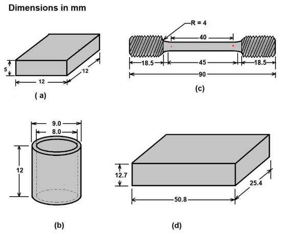
Figure 1.
Schematic representation of the three configurations of samples used for analyzing (a) layer thickness and microhardness, (b) corrosion tests, (c) tensile tests, and (d) wear tests.
Additionally, samples of nontreated API 5L grade B pipeline steel with the same geometries as shown in Figure 1 were analyzed to compare the results to the original properties.
Details of the surface finishing of each specimen and the boriding process conditions are detailed in Part I [13] of the present research. For a greater understanding of the boriding process and the experiment carried out, a brief description was taken from Part I [13] of this research:
“For appropriate surface finishing, the samples were sequentially polished with 80–1000 SiC paper (EXTEC CORPORATION, Enfield, CT, USA). After this metallographic finishing, the samples were cleaned in an ultrasonic bath for 5 min in a mixture of ethanol and distilled water (50/50). After cleaning, the samples were introduced into a stainless-steel crucible with the boriding agent, containing 5% wt. of B4C as the boron donor, 5% wt. of KBF4 as the activator, and 90% wt. of SiC as the diluent, with a powder size of 50 µm, Hef-Durferrit (DURFERRIT, GmbH, Mannheim, Germany)”.
2.2. Layers Microhardness Estimation
Hardness of the boride layers was measured using Vickers microindentation, using a Vickers micro indenter cms (Tlalnepantla, Mexico), by following the limits of the ASTM E384 standard [21]. Five hardness profiles were carried out at different zones of the layers to establish the hardness values as a function of the distance from the surface. Moreover, the anisotropic nature of the layers was established based on the changes in the hardness values across the boride layer.
During the microhardness tests, the measurement was based on the plastic deformation of the material. It was assumed that elastic recovery did not occur when the indenter was removed after the loading cycle, so the indentation print retained the shape of the indenter after the force was removed [21]. The hardness value was estimated by calculating Equation (1), as follows:
where () is the hardness if the material (Vickers), () is a constant related to the geometry of the indenter (1.8544 for microindentation), () is the applied load (kg), and () is the average of the diagonals of the indentation print (mm).
The indenter was a square-based, pyramidal-shaped diamond indenter with face angles of 136° [21]. Figure 2 is a schematic representation of the measurement method for the diagonals of the permanent impression.
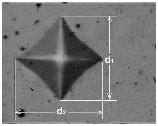
Figure 2.
Scheme of the measurement of the diagonals of the permanent print.
The hardness measurement of the boride layers was based on an ideal test where the diagonals were measured directly from the microhardness tester. However, the measured value of the hardness had several sources of errors, especially when the indentation print was very small (micrometers). Variations in the applied load, geometrical variations between diamond indenters, and human errors in measuring indentation lengths can affect the calculated hardness [21]. For this reason, the indentation prints were digitalized, and the diagonals were measured directly from the microphotographs to ensure better results.
For each sample, the hardness was determined by randomly selecting at least five profiles from the surface to the substrate. Figure 3 illustrates the hardness measurement process.
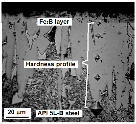
Figure 3.
Schematic of the hardness profile measurements.
2.3. Tensile Tests
The strength of steel is often the main concern. It can be measured as the maximum stress that the material can withstand. These estimations of strength are used with appropriate caution in the piping or equipment design process. It is also necessary to determine the material’s ductility, which is a measure of how much it can be deformed before it fractures. Most changes in metal composition or processing conditions can produce changes in strength and ductility. For this reason, in the present paper, yield strength, ultimate tensile strength, and ductility were determined after the obtention of stress–strain curves under different conditions.
An important parameter of the API 5L grade B steel is ductility, because the main application of this material is manufacturing pipelines that move liquid and gaseous hydrocarbons, where the pressures and the flow speed are normally high. Tensile tests were applied to the borided material to assess the changes in ductility before and after the boriding process of the specimens. The tensile tests were carried out in a Shimadzu universal machine, equipped with a load cell of 500 kg, following the limits of the ASTM E 8M standard [19], for small-size specimens (see Figure 1).
The ductility of any metal can be computed using the percentage of necking (% area reduction), according to Equation (2) [22].
where () is the percentage of area reduction, which is a measure of the ductility, and () and () are the initial and the final area (before and after the tensile tests, respectively). Another characteristic that is valuable for determining ductility is the percent of elongation, which is a ratio expressing how much a tensile specimen is stretched out or elongated during the test, compared to its original size. Equation (2) was used to determine the pipeline steel ductility after the boriding process, with the purpose of evidencing that ductility in the material was not affected by the treatment.
Two other characteristics were also determined using the tensile test: yield strength and ultimate tensile strength (UTS). These characteristics are frequently used to estimate the pipeline failure pressure [16]. The tensile test was only carried out for samples treated for 6 h at 850, 900, 950, and 1000 °C because they represent the most critical conditions studied.
2.4. Corrosion Tests
Pipelines usually transport unprocessed hydrocarbons containing impurities that can cause corrosion and erosion. This degradation mechanism could be reduced by use of a boriding process for the pipeline steel. The effect of the boriding treatment on the corrosion resistance of API 5L grade B pipeline steel was evaluated using a rotary disk-type device. Samples with the shape shown in Figure 1 were incorporated into an adapted rotary device (IKA, Wilmington, NC, USA). The tests were carried out at a constant speed of 2440 rpm for 24 h in a saline medium containing 9952 ppm of chloride content, 9992 ppm of sulfate content, and a pH of 3.29, obtained after adding HNO3. These chemical characteristics of the solution were taken from the study carried out by J.C. Velázquez and coworkers on localized corrosion in oilfield-produced waters [18]. In addition, to simulate abrasive particles, 4000 ppm of sand [23,24] was included in the solution. For the sake of comparison, another corrosion test was performed using a chemical solution with the same concentrations of chlorides and sulfates (9952 ppm of chloride content and 9992 ppm of sulfate content, respectively), with the acidity adjusted with acetic acid (1.9 mL/L) to a pH of 3.11. Organic acids are well-known for their aggressive ability to cause deterioration in oil and gas pipelines [18,25,26].
Likewise, the rotation speed used in these two cases was 2440 rpm. The mass of the sample was measured before and after the tests to evaluate the corrosion resistance. This test was only carried out for samples treated for 6 h at 850, 900, 950, and 1000 °C. The weight loss test is an accelerated test that can demonstrate the resistance of the surface to particle impact in a corrosive environment [24].
2.5. Abrasive Wear Tests
The tribological behavior of the boride layers on the surface of the API 5L grade B steel was established with an abrasive wear test using a sand/rubber apparatus, following the methodology established by the ASTM G-65 standard [20].
The weight of the hardened samples and the non-treated steel was measured before and after the wear tests using an analytical balance (0.0001 g accuracy). The test conditions were established according to the ASTM G-65 standard for hard coatings and thin films (Procedure C). Table 2 shows the test conditions used during the wear tests.
Table 2.
Test parameters for the wear assays according to the ASTM-G65 standard [20].
The morphology of the wear tracks was analyzed using optical microscopy with the aid of a GX-51 optical microscope (Olympus, Center Valley, PA, USA). The wear resistance of the treated samples was evaluated considering the loss of volume, following the procedure established by the ASTMG-65 standard, according to Equation (3) [20]:
The wear rate of the boride layers during wear tests was evaluated by calculating Archard’s equation (Equation (6)) [27]:
where () is the volume loss during the test (mm3), () is the mass loss (g), () is the density of the test material (g cm−3), () is the wear rate (mm3 N−1 m−1), and () is the sliding distance (m).
To calculate the density of the involved materials (), Gloker proposed an equation based on atomic theory, as follows [28]:
where () is the density of the corresponding surface (treated and nontreated API 5L grade B steel) (g cm−3), () is the coordination number for each crystalline cell, () is the average of the atomic weight of the corresponding elements in each surface treatment, () is the absolute unit of mass of atomic weight (1.66 × 10⁻²⁴ g), and () is the volume of the elementary cell (cm3). The density values of the corresponding surfaces are depicted in Table 3.
Table 3.
The density of the corresponding hardening surfaces is according to Equation (5) [28].
3. Results
3.1. Layer Hardness Estimations
Hardness is a necessary characteristic to assess because it indicates the resistance to localized plastic deformation. This property tends to change as the distance from the surface changes due to the boron concentration [30]. The greater the distance, the lower the hardness value. To illustrate the hardness evolution we used interval plots, where the mean was represented by a symbol and the confidence interval (a range of values that may include the population mean) [31]. The hardness evolution is depicted in Figure 4, Figure 5, Figure 6 and Figure 7 for each condition and for different levels (hardness profile measurements are illustrated in Figure 3). In all cases, the mean value of microhardness tended to increase as the treatment time increased. The hardness of the boride layer showed a stochastic nature, as did the layer thickness [32].
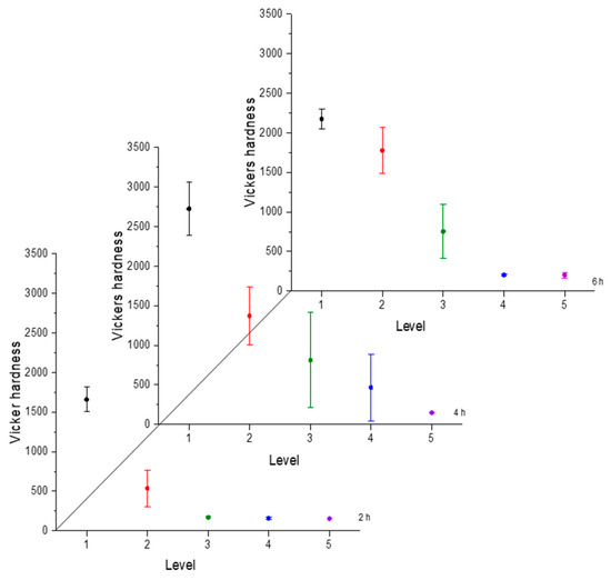
Figure 4.
Microhardness evolution after boriding treatment at 850 °C.
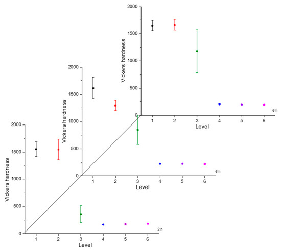
Figure 5.
Microhardness evolution after boriding treatment at 900 °C.
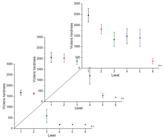
Figure 6.
Microhardness evolution after boriding treatment at 950 °C.
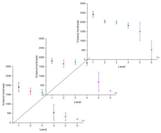
Figure 7.
Microhardness evolution after boriding treatment at 1000 °C.
From observing the interval plots corresponding to microhardness evolution, it was possible to determine that at moderate temperatures (850–950 °C), the hardness close to the surface undergoes more variability. This is because the boride layer was still in the process of consolidation. For higher temperatures (1000 °C), the microhardness variability tended to decrease because the layer was more consolidated. On the other hand, further from the surface, at moderate temperatures, the variability decreased because the boron had not diffused yet in that zone. However, at a higher temperature, further from the surface, the variability increased because the layer was in the process of formation. This was an indication that temperature plays the most important role in the boriding process of carbon steels, as mentioned in the research by P. Ruiz-Travolsi and coworkers [33].
Because the microhardness tended to decrease from the surface to the substrate, it was necessary to model how this property changes. To achieve this goal, microhardness and distance from the surface data were fitted to Equation (6).
where () is the boride layer microhardness, () is the distance from the surface, and () are parameters to be determined by nonlinear regression analysis. The values of these parameters are listed for each condition in Table 4.
Table 4.
Parameter values obtained using nonlinear regression according to Equation (6).
In the model proposed, the parameter C is the shape parameter. It represents the shape of the function. Because of the changes in this shape parameter, it tends to be more positive when the time and temperature increase, or greater than zero when the treatment temperature is 1000 °C. At moderate temperatures (850–950 °C), the microhardness does not decrease suddenly as one moves away from the surface. However, at higher temperatures, the microhardness behavior remains stable, with high values close to the surface, decreasing suddenly after a considerable distance. This behavior occurs because the layers tend to be very thick at high temperatures, so the hardness is almost constant at all layer thicknesses. However, once it is on the layer limit, the hardness decreases drastically until the substrate hardness is reached. Parameter A, which is a constant, was obtained by constraining its value to greater than the lowest hardness value measured in the boride layer in the nonlinear regression. This allowed us to obtain at least the minimum value recorded. Figure 8, Figure 9 and Figure 10 describe the microhardness behavior when it was measured away from the surface for three different conditions.
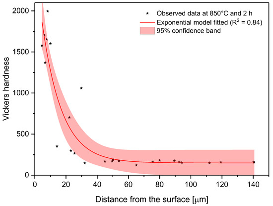
Figure 8.
Changes in microhardness as measured away from the surface for a sample treated at 850 °C and 2 h.
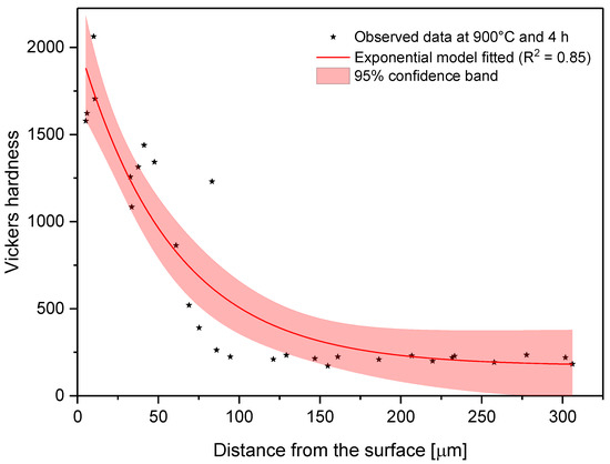
Figure 9.
Changes in microhardness as measured away from the surface for a sample treated at 900 °C and 4 h.
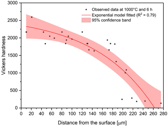
Figure 10.
Changes in microhardness as measured away from the surface for a sample treated at 1000 °C and 6 h.
3.2. Tensile Tests Results (Ductility, Yield Strength, and UTS)
A tensile test [19] using reduced-size specimens (see Figure 1) was carried out to determine the changes of some characteristics (yield strength, UTS, and ductility) after the boriding treatment. This experiment was performed on a universal testing machine, Shimadzu UH-500kNX. Figure 11 shows the engineering stress–strain curve obtained for treated and nontreated specimens.
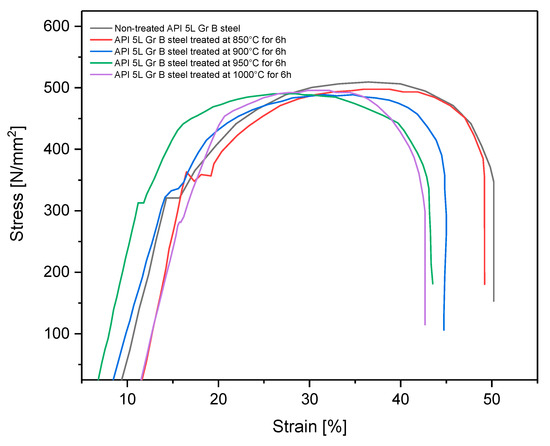
Figure 11.
Strain–stress curve for treated and non-treated API 5L grade B steel.
The tensile test obtained the yield strength, UTS, percent of reduction of area, and percent of elongation. These results are listed in Table 5.
Table 5.
Yield strength, UTS, reduced area, and elongation for treated and nontreated specimens.
All specimens that underwent the boriding process showed slightly decreased ductility because the elongation and the reduction area tended to diminish [34]. Additionally, yield strength and ultimate tensile strength also tended to decrease for all treated specimens, except those treated at 850 °C for 6 h. This partial improvement of yield strength has been observed in some cases when the pipeline steel is exposed to high temperatures, as in the isothermal aging process, and is caused by possible carbide precipitations [15,35]. This tendency for diminishment of the material strength is consistent with the information found in the literature, in which a decrease of up to 10% of the yield strength, UTS, and elongation percentage has been found [36,37]. That is, the engineering strength characteristics are highly affected by the treatment thermal conditions. However, these values remained above the minimum threshold established by the standard API 5L [38], which specifies the mechanical characteristics of these steels (specified minimum yield strength 245 MPa and 415 MPa for UTS). Yield strength and UTS are properties used for pipe design and for failure pressure estimations once the pipes are in service [14,16,39]. These results showed that after the boriding process, the pipes and fittings can be used, provided that the mechanical properties still meet the previously established requirements. The changes in these mechanical properties can not only be attributed to the hardened layer but also to the grain size changes in the steel after the thermochemical process, as indicated in Part I of this research.
3.3. Corrosion Test Results
The corrosion specimens schematized in Figure 1 in Section 2.1 of the present paper were mounted to a shaft to be rotated at 2440 rpm for 24 h in the chemical solutions indicated previously at room temperature. Table 6 shows the weight loss for each specimen.
Table 6.
Weight loss and corrosion rate results.
After analyzing the results, it was evident that when borided specimens were tested in a solution acidified with HNO3, they did not demonstrate adequate erosion–corrosion resistance. The specimens tended to diminish in weight and show an increased corrosion rate. The treated specimens lost more weight than the nontreated specimens. This suggests that treatment with boron is not only useless, but a surface with boron may actually favor deterioration. Similar issues were observed by I. Campos-Silva et al. and D. N. Tsipas et al. [25,40] in other research. In both cases, the borided layers did not show improved corrosion resistance to HNO3. This behavior has also been found in titanized carbon steels immersed in HF [41]. This means that some surface hardenings are not resistant to corrosion in some acids. This poor corrosion resistance to HNO3 of the borided API 5L grade B steel is not of concern because neither crude oil nor sour gas tends to contain a high enough HNO3 concentration when they are transmitted by pipelines. On the other hand, when the borided layers were tested under the interaction of acetic acid, they showed an improvement in erosion–corrosion resistance. The corrosion rate tended to be lower (between 10% and 20%) in borided specimens than the nontreated API 5L grade B steel. This means that borided layers can protect against erosion–corrosion in water environments even if they are acidified by organic acids, which are typically present in hydrocarbon transportation [25,26]. The improvement in the corrosion resistance in API 5L steels immersed in acids was also assessed using electrochemical techniques [42,43]. These studies have confirmed that the corrosion resistance of API 5L steels against HCl and H2SO4 can be improved when boride is applied to the surface.
The appearance of the corrosion specimens at the end of the corrosion test was recorded using digital photography. For illustration purposes, optical micrographs (see Figure 12) show the appearance of the corroded metal surface after the corrosion test for both treated and nontreated specimens.
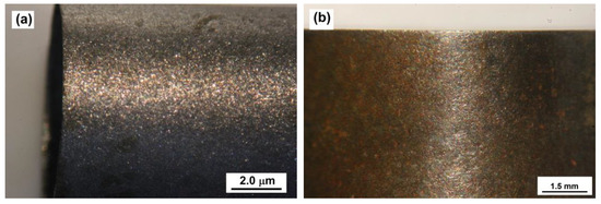
Figure 12.
Optical micrographs of nontreated (a) and treated corrosion specimen (b) surfaces upon exposure to synthetic oil-field-produced water in the presence of sand particles at 2440 rpm for 24 h.
3.4. Abrasive Wear Tests
The wear tests were carried out only in samples exposed to 850, 900, 950, and 1000 °C for 6 h each. Nontreated samples were also tested. Three samples of each condition were tested. Figure 13 shows the wear patterns resulting from the wear assays.
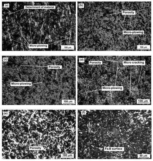
Figure 13.
Wear tracks for samples 0, 3, 6, 9, and 12 (a–e, respectively, Table 1); (f) is the surface of sample 12 with no wear track.
It was clear that the nontreated sample was the most damaged of all conditions after the wear tests. The borided samples showed the porosity characteristics of borided surfaces (see Figure 13f). By observing the micrographs, it is possible to infer that the boride layers continued to be functional even after the tests, and that the loss of volume was generalized on all the borided surfaces.
These results indicate that the boriding process could be an excellent alternative for protecting the surface of API 5L grade B steel in applications where it is exposed to abrasive wear and scratches.
The results of the wear tests, such as mass loss, loss of volume, and wear rate, are shown in Table 7.
Table 7.
Volume loss as a function of the different hardening processes.
According to the results, the wear resistance was increased, as the loss of volume of the nontreated samples was seventy times greater than for those exposed to boriding at 850 °C for 6 h, and seven times greater than the samples exposed to 1000 °C for 6 h. Interestingly, the loss in volume turned out to be inversely proportional to the treatment temperature, so the samples exposed to the highest temperature were those with the highest loss of volume (see Table 7). This apparent contradictory behavior can be explained because as the treatment temperature increased, the boride layers tended to be thicker and thicker and their hardness increased, which should be beneficial to wear resistance [44,45,46]. The loss in volume during the wear tests was also related to the brittleness of the material, and it is clear that the higher the temperature, the more brittle the layers were. Similar results were reported in our previous work [47], where the samples exposed to higher temperatures exhibited the highest loss in volume compared to those exposed to lower temperatures. Additionally, other researchers [48,49,50] have reported that layer thicknesses over 1520 μm are more resistant to abrasive and adhesive wear, which are the main wear mechanisms observed during these kinds of tests.
Moreover, the ductility of the API 5L grade B steel was inversely proportional to the temperature (see Table 5), which means that the substrate became harder as well. This could increase the brittleness of the boride layer.
4. Overall Discussion
Here, we consider the results obtained in Part I [13] and Part II of the present research, jointly analyzing the effects that different treatment conditions have on the boride layer and API 5L grade B steel. We also aimed to clarify under what conditions pipeline steel is able to be treated to minimize changes in the mechanical properties. We show that improving the mechanical surface characteristics has the advantage of making the surface resistant to scratches and dents, and the corrosion deterioration in oil-field-produced water environments containing sand particles. Finally, we discuss future studies to be carried out to confirm the viability of the applications of this research in industrial cases.
4.1. Effects of the Boriding Treatment Condition on Surface and Substrate
Much of the existing research has only analyzed the changes and improvements in the surface from the boriding process in carbon steel. For example, one researcher considered the amount of matter exposed to the thermochemical process to determine boride layer thickness with the function of sample size [33]. Wear resistance has been studied following the boriding process in AISI 1018 steel, with successful results [51]. Carbon steel also showed significant hardness improvements [52,53]. In all these previous cases, bi-phasic layers containing FeB and Fe2B were formed. In the case of oil and gas pipelines, the steel used contains microalloys that tend to restrict FeB layer formation. FeB layers typically show greater hardness and greater brittleness [29]. Therefore, the absence of FeB layers in API 5L grade B steel represents an advantage, because it does not reduce resistance to cracking forces that may propagate in long pipelines, and with it the ability to withstand large loads and pressures with the highest possible efficiency. The unique formation of Fe2B layers in API 5L steel has also been documented in other studies [42,43]. In Part I of the present research, it was explained that at higher treatment temperatures, the grains almost triple their size. These changes were made evident when the ductility changes were analyzed in Part II. If only the boride layer behavior is studied, it is feasible to conclude that a higher temperature leads to a more resistant the surface and would increase the lifetime of the pipeline section. However, at higher treatment temperatures, API 5L grade B steel tends to show reduced ductility, which could increase the risk of failures provoked by the changes of loads when the fluids are transmitted, i.e., production increasing, water hammer, and changes in density because of weather changes and altitude. Likewise, it was observed that treatment carried out at 850 °C does not significantly modify grain size, ductility, yield strength, or UTS. This means that a moderate treatment temperature could be the best choice for improving the pipeline steel surface.
4.2. Erosion–Corrosion and Wear Resistance
After being treated with boron, the API 5L grade B steel specimens seemed to be more resistant to erosion–corrosion, especially if the fluid contained a considerable amount of organic acids. More accurate values must be found in a future study because corrosion has a stochastic nature, as has been demonstrated in other works [54]. However, the tendency is clear: more stable layers at higher treatment temperatures tend to provide greater protection. After studying the wear resistance, it was clear that boride layers can provide good protection against scratches and some dents, because the sand/rubber test did not cause an increase in weight loss compared to the nontreated specimens of API 5L grade B (seventy times higher). Additionally, the temperature of the treatment seems to play an important role in the wear resistance of the boride layers, because the layers formed at 850 and 900 °C showed better wear resistance than those obtained at 950 and 1000 °C (almost ten times higher). In this context, it seems that the best choice for improving the API 5L grade B steel surface is to treat it with boron at moderate temperatures (about 850 °C), because ductility and strength are not modified significantly, and the surface is made sufficiently resistant to erosion–corrosion and wear. The boriding process tends to be suitable for materials that are exposed to wear due to metal friction, such as gears and shafts [55]. In the oil and gas industry, this erosion and wear resistance treatment may also be appropriate for pipes, elbows, tees, and other fittings. Similar findings were obtained by Eugene Medvedovski and Maksim Antonov [56] for carbon steels J55 and L80, but with a biphasic boride layer formed (FeB + Fe2B) over this material.
4.3. Future Works for Industrial Applications
Future works of boride layer formation on pipeline steels for industrial and real-case applications may include:
- Changes in the mechanical properties of the pipeline steels because of the thermochemical process.
- Assessment of the corrosion resistance considering the nature of the acidity, because some acids can diminish the protective characteristics of the boride layers.
- The use of electrochemical techniques to assess the corrosion protection in borided API 5L grade B steel. Open-circuit potential to evaluate the tendency to form oxides, electrochemical impedance spectroscopy to study the possible mechanism, and Tafel to determine the instantaneous corrosion rate.
- The analysis of the interaction of the boride layer on pipeline steels and other corrosion mechanisms, especially when the geometry of the pipe fitting is involved.
- A more in-depth study on the interaction and influence of steel microalloys on the boride layers, as well as other pipeline steels from the API 5L series.
5. Conclusions
- Higher temperatures tend to form more stable boride layers with greater hardness. The stability of the boride layers can be observed when the hardness is assessed in the specimen cross-section; it is necessary to move away from the surface to note a drop in hardness.
- Increments in the grain size at higher temperatures of the thermochemical treatment provoke changes in the ductility of pipeline steel. This is important because the main application of API 5L grade steel is to manufacture pipes, which are often under loads that cause deformities.
- When API 5L grade B steel is subjected to powder-pack boriding, this can offer protection against erosion–corrosion mechanisms in oil-field-produced water environments with sand particles, as long as they are not acidified by nitric acid. Boriding of API 5L grade steel offers satisfactory protection if the fluid contains acetic acid. Increasing the treatment temperature in the boriding process does not significantly improve the corrosion resistance of the studied steel.
- Sand/rubber tests confirmed the improvement in wear surface resistance of the borided pipeline steel compared to the nontreated material. However, increasing the treatment temperature did not generate greater wear resistance.
- It seems that the best condition under which to treat API 5L grade B steel with boron is at the lowest possible temperature, because this prevents considerable modification to the substrate’s mechanical characteristics, while offering adequate corrosion and wear resistance.
Author Contributions
Conceptualization, J.C.V. and E.H.-S., methodology, P.A.R.-T. and R.T.-R.; validation, J.C.V., E.H.-S. and L.M.A.-M.; formal analysis, J.C.V. and E.H.-S.; investigation, J.G.M.-H., resources, J.C.V. and E.H.-S.; data curation, L.M.A.-M. and R.C.-S., writing—original draft preparation, J.C.V.; writing—review and editing, J.C.V. and E.H.-S.; visualization, J.C.V.; supervision, E.H.-S.; project administration, R.C.-S., J.C.V., and E.H.-S.; funding acquisition, E.H.-S. All authors have read and agreed to the published version of the manuscript.
Funding
This work was supported by research Grant 20210181 of the Instituto Politécnico Nacional in Mexico.
Institutional Review Board Statement
Not applicable.
Informed Consent Statement
Not applicable.
Data Availability Statement
The data that support the findings of this study are available from the corresponding author upon reasonable request.
Acknowledgments
The authors wish to thank the Center of Nanosciences and Micro-Nano Technologies of the Instituto Politécnico Nacional for their cooperation. Additionally, they would like to thank Instituto Tecnológico de Estudios Superiores Monterrey in Mexico for its collaboration in developing this work.
Conflicts of Interest
The authors declare no conflict of interest.
References
- Liu, H.; Zhou, Z.; Liu, M. A Probability Model of Predicting the Sand Erosion Profile in Elbows for Gas Flow. Wear 2015, 342–343, 377–390. [Google Scholar] [CrossRef]
- Parsi, M.; Najmi, K.; Najafifard, F.; Hassani, S.; McLaury, B.S.; Shirazi, S.A. A Comprehensive Review of Solid Particle Erosion Modeling for Oil and Gas Wells and Pipelines Applications. J. Nat. Gas Sci. Eng. 2014, 21, 850–873. [Google Scholar] [CrossRef]
- Kanesan, D.; Mohyaldinn, M.E.; Ismail, N.I.; Chandran, D.; Liang, C.J. An Experimental Study on the Erosion of Stainless Steel Wire Mesh Sand Screen Using Sand Blasting Technique. J. Nat. Gas Sci. Eng. 2019, 65, 267–274. [Google Scholar] [CrossRef]
- Reda, Y.; Gamal, A.; Abdel-Karim, R.; El-Raghy, S.M. Erosion–Corrosion Behaviour of ASTM A106 GR.B Carbon Steel Pipelines. J. Bio Tribo-Corros 2023, 9, 8. [Google Scholar] [CrossRef]
- Chen, P.; Cui, B.; Li, J.; Zheng, J.; Zhao, Y. Particle Erosion under Multiphase Bubble Flow in Horizontal-Vertical-Upward Elbows. Powder Technol. 2022, 397, 117002. [Google Scholar] [CrossRef]
- Svedeman, S.J.; Arnold, K.E. Criteria for Sizing Multiphase Flowlines for Erosive/Corrosive Service. SPE Prod. Facil. 1994, 9, 74–80. [Google Scholar] [CrossRef]
- Salama, M.M. An Alternative to API 14E Erosional Velocity Limits for Sand Laden Fluids. In Proceedings of the Offshore Technology Conference, Houston, TX, USA, 4–7 May 1998. [Google Scholar] [CrossRef]
- Jordan, K.G. Erosion in Multiphase Production of Oil & Gas. In CORROSION 98; NACE: San Diego, CA, USA, 1998; p. 98058. [Google Scholar]
- Cosham, A.; Hopkins, P. The Effect of Dents in Pipelines—Guidance in the Pipeline Defect Assessment Manual. Int. J. Press. Vessel. Pip. 2004, 81, 127–139. [Google Scholar] [CrossRef]
- Tian, X.; Zhang, H. Failure Pressure of Medium and High Strength Pipelines with Scratched Dent Defects. Eng. Fail. Anal. 2017, 78, 29–40. [Google Scholar] [CrossRef]
- Tian, X.; Zhang, H. Failure Criterion of Buried Pipelines with Dent and Scratch Defects. Eng. Fail. Anal. 2017, 80, 278–289. [Google Scholar] [CrossRef]
- Vishnuvardhan, S.; Murthy, A.R.; Choudhary, A. A Review on Pipeline Failures, Defects in Pipelines and Their Assessment and Fatigue Life Prediction Methods. Int. J. Press. Vessel. Pip. 2023, 201, 104853. [Google Scholar] [CrossRef]
- Alcantar-Martínez, L.M.; Ruiz-Trabolsi, P.; Tadeo-Rosas, R.; Miranda-Hernández, J.; Terán-Méndez, G.; Velázquez, J.C.; Hernández-Sánchez, E. Improving the Surface Properties of an API 5L Grade B Pipeline Steel by Applying the Boriding Process. Part I: Kinetics and Layer Characterization. Coatings 2023, 13, 298. [Google Scholar] [CrossRef]
- Velázquez, J.C.; González-Arévalo, N.E.; Díaz-Cruz, M.; Cervantes-Tobón, A.; Herrera-Hernández, H.; Hernández-Sánchez, E. Failure Pressure Estimation for an Aged and Corroded Oil and Gas Pipeline: A Finite Element Study. J. Nat. Gas Sci. Eng. 2022, 101, 104532. [Google Scholar] [CrossRef]
- González-Arévalo, N.E.; Velázquez, J.C.; Díaz-Cruz, M.; Cervantes-Tobón, A.; Terán, G.; Hernández-Sanchez, E.; Capula-Colindres, S. Influence of Aging Steel on Pipeline Burst Pressure Prediction and Its Impact on Failure Probability Estimation. Eng. Fail. Anal. 2021, 120, 104950. [Google Scholar] [CrossRef]
- Velázquez, J.C.; Caleyo, F.; Hallen, J.M.; Romero-Mercado, O.; Herrera-Hernandez, H. Probabilistic Analysis of Different Methods Used to Compute the Failure Pressure of Corroded Steel Pipelines. Int. J. Electrochem. Sci. 2013, 2013, 11356–11370. [Google Scholar]
- Terán, G.; Capula-Colindres, S.; Velázquez, J.C.; Angeles-Herrera, D.; Torres-Santillán, E. On the Influence of the Corrosion Defect Size in the Welding Bead, Heat-Affected Zone, and Base Metal in Pipeline Failure Pressure Estimation: A Finite Element Analysis Study. J. Press. Vessel. Technol. 2019, 141, 031001-1–031001-8. [Google Scholar] [CrossRef]
- Velázquez, J.C.; Cruz-Ramirez, J.C.; Valor, A.; Venegas, V.; Caleyo, F.; Hallen, J.M. Modeling Localized Corrosion of Pipeline Steels in Oilfield Produced Water Environments. Eng. Fail. Anal. 2017, 79, 216–231. [Google Scholar] [CrossRef]
- ASTM E8/E8M; Standard Test Methods for Tension Testing of Metallic Materials. ASTM Volume 03.01 Metals—Mechanical Testing; Elevated and Low-Temperature Tests. Metallography. ASTM International: West Conshohocken, PA, USA, 2016.
- ASTM G65-00; Standard Test Method for Measuring Abrasion Using the Dry Sand/Rubber Wheel Apparatus. American Society for Testing and Materials. ASTM International: West Conshohocken, PA, USA, 2015.
- ASTM E384; Standard Test Method for Microindentation Hardness of Materials. ASTM International: West Conshohocken, PA, USA, 2013.
- Vable, M. Mechanics of Materials; Oxford University Press: New York, NY, USA, 2008. [Google Scholar]
- Tandon, S.; Gao, M.; McNealy, R. Erosion-Corrosion Failure of A Carbon Steel Pipe Elbow-A Case Study. In CORROSION 2009; NACE: Atlanta, GA, USA, 2009; p. 9479. [Google Scholar]
- Cabrera-Sierra, R. Corrosion Studies of Carbon Steel Immersed in NACE Brine by Weight Loss, EIS and XRD Techniques. Int. J. Electrochem. Sci. 2016, 11, 10185–10198. [Google Scholar] [CrossRef]
- Nešić, S. Key Issues Related to Modelling of Internal Corrosion of Oil and Gas Pipelines—A Review. Corros. Sci. 2007, 49, 4308–4338. [Google Scholar] [CrossRef]
- Zhang, G.A.; Cheng, Y.F. On the Fundamentals of Electrochemical Corrosion of X65 Steel in CO2-Containing Formation Water in the Presence of Acetic Acid in Petroleum Production. Corros. Sci. 2009, 51, 87–94. [Google Scholar] [CrossRef]
- Holmberg, K.; Ronkainen, H.; Matthews, A. Tribology of Thin Coatings. Ceram. Int. 2000, 26, 787–795. [Google Scholar] [CrossRef]
- von Matuschka, M.G. Boronizing, 1st ed.; Carl Hanser: Munich, Germany, 1980. [Google Scholar]
- Hernández-Sánchez, E.; Velázquez, J.C. Kinetics of Growth of Iron Boride Layers on a Low-Carbon Steel Surface. In Laboratory Unit Operations and Experimental Methods in Chemical Engineering; InTech: Vienna, Austria, 2018. [Google Scholar] [CrossRef]
- Chino-Ulloa, A.; Ruiz-Trabolsi, P.A.; Torres-Avila, I.P.; Orozco-Álvarez, C.; Tadeo-Rosas, R.; Velázquez, J.C.; Hernández-Sánchez, E. Kinetics and Mechanical Characterization of Hard Layers Obtained by Boron Diffusion in 80/20 Nickel–Chromium Alloy. Coatings 2022, 12, 1387. [Google Scholar] [CrossRef]
- Minitab 20 Support. Interpret the Key Results for Interval Plot. Available online: https://support.minitab.com/en-us/minitab/20/help-and-how-to/graphs/interval-plot/interpret-the-results/key-results/ (accessed on 10 December 2022).
- Velázquez-Altamirano, J.C.; Torres-Avila, I.P.; Teran-Méndez, G.; Capula-Colindres, S.I.; Cabrera-Sierra, R.; Carrera-Espinoza, R.; Hernández-Sánchez, E. A Stochastic Model and Investigation into the Probability Distribution of the Thickness of Boride Layers Formed on Low-Carbon Steel. Coatings 2019, 9, 756. [Google Scholar] [CrossRef]
- Ruiz-Trabolsi, P.A.; Velázquez, J.C.; Orozco-Álvarez, C.; Carrera-Espinoza, R.; Yescas-Hernández, J.A.; González-Arévalo, N.E.; Hernández-Sánchez, E. Kinetics of the Boride Layers Obtained on AISI 1018 Steel by Considering the Amount of Matter Involved. Coatings 2021, 11, 259. [Google Scholar] [CrossRef]
- ADMET Material Testing System Manufacturer. Materials Testing Glossary. Available online: https://www.admet.com/materials-testing-glossary/#:~:text=Elongation%20is%20defined%20as%20the,the%20original%20cross%20sectional%20area (accessed on 12 December 2022).
- Vargas-Arista, B.; Hallen, J.M.; Albiter, A. Effect of Artificial Aging on the Microstructure of Weldment on API 5L X-52 Steel Pipe. Mater. Charact. 2007, 58, 721–729. [Google Scholar] [CrossRef]
- Günen, A.; Kurt, B.; Somunkιran, İ.; Kanca, E.; Orhan, N. The Effect of Process Conditions in Heat-Assisted Boronizing Treatment on the Tensile and Bending Strength Characteristics of the AISI-304 Austenitic Stainless Steel. Phys. Met. Metallogr. 2015, 116, 896–907. [Google Scholar] [CrossRef]
- Calik, A.; Sahin, O.; Ucar, N. Mechanical Properties of Boronized AISI 316, AISI 1040, AISI 1045 and AISI 4140 Steels. Acta Phys. Pol. A 2009, 115, 694–698. [Google Scholar] [CrossRef]
- American Petroleum Institute. API 5L Specifications for Line Pipe; American Petroleum Institute, API: Houston, TX, USA, 2007. [Google Scholar]
- Caleyo, F.; Valor, A.; Venegas, V.; Espina-Hernandez, J.H.; Velázquez, J.C.; Hallen, J.M. Accurate Corrosion Modeling Improves Reliability Estimations. Oil Gas J. 2012, 110, 122–129. [Google Scholar]
- Campos-Silva, I.E.; Rodríguez-Castro, G.A. Boriding to Improve the Mechanical Properties and Corrosion Resistance of Steels. In Thermochemical Surface Engineering of Steels; Elsevier: Amsterdam, The Netherlands, 2015; pp. 651–702. [Google Scholar] [CrossRef]
- Günen, A.; Kanca, Y.; Karahan, İ.H.; Karakaş, M.S.; Gök, M.S.; Kanca, E.; Çürük, A. A Comparative Study on the Effects of Different Thermochemical Coating Techniques on Corrosion Resistance of STKM-13A Steel. Metall. Mater. Trans. A 2018, 49, 5833–5847. [Google Scholar] [CrossRef]
- Sliman, G.; SAMI, Z.; Abdelkader, R.; Tassi, H. Comparative Study on Electrochemical Corrosion Behavior of Boronized X52 Steel in 1 M HCl and H2SO4 Solutions. Metall. Mater. Eng. 2022, 28, 531–538. [Google Scholar] [CrossRef]
- Hocine, T.; Sami, Z.; Omar, A. Effect of Martensite Morphologies on Corrosion in 5% H2SO4 Solution of Borided X70 Dual Phase Steel. Ann. Chim. Sci. Matér. 2021, 45, 69–74. [Google Scholar] [CrossRef]
- Erdemir, A.; Bindal, C.; Zuiker, C.; Savrun, E. Tribology of Naturally Occurring Boric Acid Films on Boron Carbide. Surf. Coat. Technol. 1996, 86–87, 507–510. [Google Scholar] [CrossRef]
- Hernández-Sanchez, E.; Chino-Ulloa, A.; Velazquez, J.C.; Herrera-Hernández, H.; Velázquez-Mancilla, R.; Carrera-Espinoza, R. Effect of Relative Humidity on the Tribological Properties of Self-Lubricating H3BO3 Films Formed on the Surface of Steel Suitable for Biomedical Applications. Adv. Mater. Sci. Eng. 2015, 2015, 436597. [Google Scholar] [CrossRef]
- Ruiz-Trabolsi, P.A.; Chino-Ulloa, A.; Miranda-Hernández, J.G.; Tadeo-Rosas, R.; Carrera-Espinoza, R.; Velázquez, J.C.; Hernández-Sánchez, E. A Comparative Analysis of the Tribological Behavior of Hard Layers Obtained by Three Different Hardened-Surface Processes on the Surface of AISI 4140 Steel. Crystals 2022, 12, 298. [Google Scholar] [CrossRef]
- Hernández-Sánchez, E.; Velázquez, J.C.; Castrejón-Flores, J.L.; Chino-Ulloa, A.; Avila, I.P.T.; Carrera-Espinoza, R.; Yescas-Hernández, J.A.; Orozco-Alvarez, C. Tribological Behavior of Borided AISI 316L Steel with Reduced Friction Coefficient and Enhanced Wear Resistance. Mater. Trans. 2019, 60, 156–164. [Google Scholar] [CrossRef]
- Rodríguez-Castro, G.; Campos-Silva, I.; Chávez-Gutiérrez, E.; Martínez-Trinidad, J.; Hernández-Sánchez, E.; Torres-Hernández, A. Mechanical Properties of FeB and Fe2B Layers Estimated by Berkovich Nanoindentation on Tool Borided Steel. Surf. Coat. Technol. 2013, 215, 291–299. [Google Scholar] [CrossRef]
- Meléndez, E.; Campos, I.; Rocha, E.; Barrón, M.A. Structural and Strength Characterization of Steels Subjected to Bonding Thermochemical Process. Mater. Sci. Eng. A 1997, 234–236, 900–903. [Google Scholar] [CrossRef]
- Campos-Silva, I.; Ortiz-Domínguez, M.; Keddam, M.; López-Perrusquia, N.; Carmona-Vargas, A.; Elías-Espinosa, M. Kinetics of the Formation of Fe2B Layers in Gray Cast Iron: Effects of Boron Concentration and Boride Incubation Time. Appl. Surf. Sci. 2009, 255, 9290–9295. [Google Scholar] [CrossRef]
- Carrera-Espinoza, R.; Figueroa-López, U.; Martínez-Trinidad, J.; Campos-Silva, I.; Hernández-Sánchez, E.; Motallebzadeh, A. Tribological Behavior of Borided AISI 1018 Steel under Linear Reciprocating Sliding Conditions. Wear 2016, 362–363, 1–7. [Google Scholar] [CrossRef]
- Campos-Silva, I.; Hernández-Sánchez, E.; Rodríguez-Castro, G.; Cimenoglu, H.; Nava-Sánchez, J.L.; Meneses-Amador, A.; Carrera-Espinoza, R. A Study of Indentation for Mechanical Characterization of the Fe2B Layer. Surf. Coat. Technol. 2013, 232, 173–181. [Google Scholar] [CrossRef]
- Jiang, J.; Wang, Y.; Zhong, Q.; Zhou, Q.; Zhang, L. Preparation of Fe2B Boride Coating on Low-Carbon Steel Surfaces and Its Evaluation of Hardness and Corrosion Resistance. Surf. Coat. Technol. 2011, 206, 473–478. [Google Scholar] [CrossRef]
- Velázquez, J.C.; Hernández-Sánchez, E.; Terán, G.; Capula-Colindres, S.; Diaz-Cruz, M.; Cervantes-Tobón, A. Probabilistic and Statistical Techniques to Study the Impact of Localized Corrosion Defects in Oil and Gas Pipelines: A Review. Metals 2022, 12, 576. [Google Scholar] [CrossRef]
- Kumaravel, D.; Arunkumar, K. Improve the Wear Property of En19 Steel by Boronizing Process. In Advances in Manufacturing Processes; Springer: Singapore, 2019; pp. 123–131. [Google Scholar] [CrossRef]
- Medvedovski, E.; Antonov, M. Erosion Studies of the Iron Boride Coatings for Protection of Tubing Components in Oil Production, Mineral Processing and Engineering Applications. Wear 2020, 452–453, 203277. [Google Scholar] [CrossRef]


Disclaimer/Publisher’s Note: The statements, opinions and data contained in all publications are solely those of the individual author(s) and contributor(s) and not of MDPI and/or the editor(s). MDPI and/or the editor(s) disclaim responsibility for any injury to people or property resulting from any ideas, methods, instructions or products referred to in the content. |
© 2023 by the authors. Licensee MDPI, Basel, Switzerland. This article is an open access article distributed under the terms and conditions of the Creative Commons Attribution (CC BY) license (https://creativecommons.org/licenses/by/4.0/).