1. Introduction
When a shaping tool is operating, its surface, being affected by friction forces, experiences a combination of wear types [
1]. In particular, abrasive and adhesive (seizure) wears are predominant for cold-formed steel dies [
2,
3]. The abrasive wear of the tool surface is due to its interaction with solid particles present in the processed structural alloys, and with oxides, carbides, silicides, and the like, newly formed at local tribological contact sites where “temperature flashes” occur as a result of friction [
2,
4,
5]. The intensity of abrasive wear of a surface is inversely proportional to its hardness [
6]. Molecular adhesive wear occurs when the surfaces of the contacting bodies are brought extremely close together at tribological contacts, which results in molecular interactions between the surfaces. The greater the friction force and the lower the surface roughness, the higher the probability of molecular interaction. According to the molecular mechanical model proposed by Kragelsky [
6], a friction force
F can be described as:
where
τmol (N/m
2) and
τmech (N/m
2) are, respectively, the molecular and the mechanical component of the force, and
Sact.mol (m
2) and
Sact.mech (m
2) are the respective actual areas of molecular and mechanical interaction.
According to Kragelsky’s theory, there are two factors responsible for the occurrence of a friction force:
(i) the force of resistance to the movement of one body relative to another that arises due to atomic and molecular interactions at the sites of actual contact between the bodies (the molecular component of the friction force) and
(ii) the hard microirregularities present on the surface of one of two contacting bodies that embed into the surface layers of the less hard body and deform these layers when the bodies slide relative to each other.
Therefore, it seems logical to state that the intensity of surface wear is proportional to the
n power of the friction coefficient [
6], where
n depends on the friction conditions and the properties of the contacting materials in tribocouplings. Thus, it is obvious that in order to reduce the wear rate of the working surface of a tool, it is necessary to provide both a low coefficient of friction of the contacting bodies and a quite high hardness of the surface layer.
The deposition of thin hard coatings on the surfaces of tools and commercial products increases their durability and wear resistance [
7,
8]. For these purposes, coatings based on the nitrides and carbides of groups IV–VI of the periodic table are mainly used, which are characterized by a relatively high hardness compared to the tool materials [
9,
10,
11,
12]. The first hardening coatings used in industry were TiN and CrN coatings. The merits of TiN coatings are their high hardness, high chemical stability, and excellent adhesion to substrates. Their weaknesses is a rather high coefficient of friction (0.5–0.6) [
13]. CrN coatings show high temperature and corrosion resistance, higher ductility and fracture toughness, as well as a low coefficient of friction (0.3–0.4), but their hardness is less in comparison with the TiN coatings [
14]. Because of the noted shortcomings, the main function of TiN and CrN coatings is to harden tools used for shaping polymers and soft alloys. It seems reasonable, in terms of practical possibilities and scientific significance, to explore options for combining the merits of two TiN and CrN compounds in a single coating having high hardness and low friction properties. A modern scientific and technological trend in the deposition of protective and hardening coatings on tools and machine parts, providing a set of properties for the coatings, is to produce multilayer structures of the deposited material, where each of the layers performs its specific function [
15]. Recently, multi-layer coatings have shown enhanced mechanical [
16,
17,
18] and tribotechnical properties [
15,
19,
20] in comparison with single-layer coatings. Multilayering is known to improve both hardness and toughness by means of different mechanisms, such as the threading of dislocations through the interfaces between the coating layers, the generalized Hall-Petch-like effect, and crack deflections in the interfaces [
21,
22,
23,
24]. Therefore, multilayer coatings show considerable promise as a means for the protecting and hardening of cutting and die tools and other mechanical items [
25,
26,
27]. Although numerous reports on the enhanced mechanical and tribotechnical properties of CrN/TiN multilayer coatings are available in the literature, there are almost no publications that would describe complex studies of these coatings deposited on cold work die steels.
The aim of this work was to study the influence of the architecture of CrN/TiN multi-layer coatings, deposited on Cr12MoV steel samples, on the microstructure and phase composition and on the mechanical and tribological characteristics of the coatings and to investigate their heat resistance and thermal stability using synchrotron-radiation-based X-ray phase analysis.
2. Materials and Methods
The coatings were produced by the vacuum-arc plasma-assisted method using a modernized NNV6.6-I1 facility («Bulat») [
28,
29] equipped with two electric arc evaporators (80 mm diameter cathodes) and an additional source of gas plasma (PINK, a hollow hot cathode plasma generator [
30]). The experimental facility was evacuated with a high vacuum pumping system based on a TMN-500 turbomolecular pump. The setup incorporated a system of planetary rotation of the sample holder and a double (Ar and N
2) gas filling system. The electric arc evaporators, one with a chromium (99.5% purity) cathode and the other with a titanium (VT1-0) cathode, were fixed on the side walls of the working chamber. The PINK generator was fixed on the door of the vacuum chamber. The stainless-steel inner walls of the vacuum chamber served as the anode for the metal and gas plasma sources. The PINK generator was used for cleaning, heating and additional ionization of both the gas and the metal component of the plasma, assisting the growth of the coating layers. The process of vacuum-arc deposition with additional assistance by a high-density gas-discharge plasma increases the probability of synthesis of the necessary functional compounds in the formed coating due to a higher degree of ionization of the reaction gas molecules.
Preliminarily hardened Cr12MoV die steel was used as a substrate material (chemical composition: (1.45–1.65)% C; (11–12.5)% Cr; (0.4–0.6)% Mo; (0.15–0.3)% V, silicon, manganese, nickel, sulfur, phosphorus and copper with a content of less than 0.5%). The samples were plates 26 × 15 × 6 mm in size. They were polished and, before being loaded into the vacuum chamber, cleaned with gasoline and then with acetone in an ultrasonic bath. In addition, the substrate material was technically pure titanium, VT1-0, (for the TEM analysis) and tungsten carbide, WC-8%Co, (for the study of synchrotron-radiation-based X-ray phase analysis). Coating deposition parameters were chosen taking into account previous studies [
4,
12,
28]. During the deposition, the sample holder rotated around the central axis of the chamber, 200 mm away from the axis, at a rotation speed of 3.5 rpm, and also around its own axis. Prior to the start of the experiment, the vacuum chamber was evacuated by the turbomolecular pump to a limiting pressure of 10
–2 Pa. The working pressure was set at 0.3 Pa by supplying the working argon gas through the PINK generator. When a gas discharge was ignited and a bias voltage of –600 V was applied to the sample holder, the samples were heated to a temperature of about 400 °C. The gas plasma source current was about 90 A in all deposition modes. All of the coatings were deposited in a nitrogen-argon gas mixture (90% N
2 and 10% Ar) at a pressure of 0.6 Pa; the evaporator currents were 80 A (Ti) and 90 A (Cr), the substrate bias voltage was –150 V, and the substrate temperature was 390–400 °C. To produce multilayer coatings, a Cr sublayer of thickness of about 40 nm was deposited as an adhesive layer, and then a CrN layer was deposited and a TiN layer served as the final layer. For a comparative analysis of the properties of the coatings, along with the multi-layer CrN/TiN coatings, single-layer CrN and TiN coatings deposited under similar conditions were used. The total deposition time for all coatings was 160 min. The thickness of all coatings was 3.5–4 µm. The multi-layer coatings with alternating CrN and TiN layers was grown by the on/off switching of two arc evaporators with cathodes made of titanium and chromium. The controlled parameter was the thickness of each layer in the multi-layer coating, depending on the layer deposition time. The layer deposition time for an 8-layer coating was 22 min for CrN and 18 min for TiN. For a 16-layer coating, it was 11 min for CrN and 9 min for TiN. For a 32-layer coating, it was 5.5 min for CrN and 4.5 min for TiN. The thickness of each CrN and TiN layers and the number of layers varied: an 8-layer coating (~500 nm thickness of each layer), a 16-layer coating (~250 nm thickness of each layer), and a 32-layer coating (~125 nm thickness of each layer) were the subjects of investigation.
The structure of the coating was studied using transmission electron microscopy (TEM) in a JEOL JEM-2100 F electron microscope (Tokyo, Japan). Thin foils (100–200 nm) were prepared from the sections of the titanium-substrate coating for TEM analyses using a standard cutting process, mechanical abrasive grinding, and Ar+ ion etching in an Ion Slicer EM-09100 IS machine (JEOL, Tokyo, Japan). The phase composition of the coatings was determined by an X-ray diffraction analysis, which was conducted using a Shimadzu XRD-7000S diffractometer (Shimadzu, Kyoto, Japan) with CuK
α radiation. To analyze the phase composition, the Crystallographica Search-Match code and PDF 4+ databases were used in combination with the Powder Cell 2.4 full profile analysis code. Nanoindentation of the coatings was carried out using a NANO Hardness Tester NHT-S-AX-000X (CSEM, Neuchâtel, Switzerland). Using a Berkovich indenter, the load applied to the sample surface was increased from zero to 25 mN at and then reduced to zero with a frequency of 10 Hz. The nanoindentation data were analyzed by the Oliver–Pharr method. Tribotechnical testing of the coatings was carried out using a Tribotechnic tribometer (Clichy, France) at a reciprocating movement of the sample relative to the counterbody under dry friction conditions. The counterbody was an Al
2O
3 ball 6 mm in diameter. The speed of movement of the sample during the test was 25 mm/s. The load on the ball was 5 N, the track length was 5 mm, and the friction path length was 50–200 m. The wear intensity was estimated by the formula:
where
Kw is the wear factor,
S is the track cross section (mm
2),
E is the eccentric length (mm),
Fn is the load normal to the friction surface (N), and
Sl is the sliding length (m). During the testing procedure, the current values of the friction coefficient were measured. The procedure complied with the ISO 7148, ASTM G99-95a, and ASTM G133-95 international standards. The surface roughness of the bare and coated samples was measured using a contact profilometer. The samples of a 32-layer CrN/TiN coating were tested for resistance to high temperatures in an oxidizing medium and in a vacuum at a pressure of 5 × 10
–3 mbar. Measurements were carried out using the in situ diffractometer of the Precision Diffractometry II station in SR channel No. 6 of the VEPP-3 electron storage ring (G.I. Budker Institute of Nuclear Physics, Siberian Branch of the Russian Academy of Sciences, Novosibirsk, Russia). The samples were heated in an Anton Paar HTK-2000 high-temperature X-ray chamber with a platinum heater, which simultaneously served as a sample holder. The operating wavelength was 0.172 nm; the rate of heating in air and in vacuum was 10 °C/min and 15 °C/min, respectively. X-ray diffraction patterns were recorded using an OD-3M-350 position-sensitive single-coordinate detector with an exposure time of 1 min/frame.
3. Results and Discussion
TEM was used for the structural characterization of the coating.
Figure 1a–c show the bright-field cross sectional TEM images of the 32-layer CrN/TiN coating. The coating is a fully dense columnar and lamellar structure of the CrN and TiN layers alternating in growth direction, and are shown as dark and bright layers, respectively. The TiN layers appear to be lighter and brighter than the CrN layers because of the lower scattering factor of Ti atoms compared to Cr atoms [
17,
19]. The total thickness of the 32-layer coating is 3.5 µm (
Figure 1a) In the TEM imaging analysis, a well-defined CrN and TiN interface was observed.
Figure 1b shows a Cr adhesive layer of about 40 nm thick. The CrN layers are about 125 nm thick and the TiN layers are about 111 nm thick (
Figure 1b). Each layer of CrN and TiN (
Figure 1c) consists of nanolayers with a CrN nanolayer of about 7 nm and a TiN nanolayer of about 7–8 nm.
Phase composition of multi-layers coatings was carried out with XRD analysis and the patterns are presented in
Figure 2. In addition, XRD patterns of CrN and TiN single-layer coatings allow one to track the peak shift. The XRD patterns of CrN/TiN multi-layer coatings with decreasing thickness of each CrN and TiN layer are arranged from bottom to top. All of the coatings reveal a face-centered cubic (c) structure with highly oriented (111) growth. It is known that CrN exists in different phases (c-CrN and b-Cr
2N), and there is a limited range of nitrogen concentration wherein stoichiometric phases of TiN and CrN with an NaCl structure exist. The intensity of (200) orientation for both TiN and CrN was very low. Other reflection planes such as (220) and (311) were completely absent in the diffraction patterns (not plotted in the figure). This shows that under these deposition conditions, both TiN and CrN coatings were highly oriented along the (111) direction. A prominent preferential orientation of the TiN and CrN crystals is observed along the (111) plane, possibly originating from competitive growth as a result of both diffusion and elastic strain energy [
31]. Due to the presence of compressive residual stress in coatings caused by the thermal expansion coefficient difference between the Cr12MoV steel substrate and nitride layers, cumulative main peaks have shifted towards higher 2θ values. The peaks’ of the multi-layer coatings are wide enough and of low-intensity, indicating a nanostructure, which was confirmed as a TEM.
Nanoindentation measurements were carried out for the CrN/TiN multi-layer coatings and the CrN and TiN single-layer coatings at room temperature. For hardness measurements, indentations were made on the coatings using a Berkovich diamond indenter. After pressing the indenter on to the coatings, the load was increased at a predetermined rate (50 mN/min) to the desired maximum load and then decreased at the same rate (50 mN/min) to zero. For all of the coatings, the maximum applied load was 25 mN. For each loading and unloading cycle, the load was plotted against the displacement of the indenter.
Figure 3a shows typical load-displacement curves for the test coatings. The hardness (H) and elastic modulus (E) values for the tested samples are mentioned in
Figure 3b. The indentation depth, ratio of hardness and elastic modulus—H/E and H
3/E
2 of the test coatings are illustrated in
Table 1. The maximum indentation depth for the CrN single-layer coating was approximately 260 nm, which is less than 1/10th of the coating thickness (
Table 1 and
Figure 3a). The TiN single-layer coating and the CrN/TiN multi-layer coatings showed smaller maximum indentation depths of 226 and ~238 nm, respectively (
Table 1 and
Figure 3a). Maximum hardness was observed for the TiN sample and was 31 GPa. Minimum hardness was observed for the CrN sample and was measured at 24 GPa. The multi-layer coatings had hardness values (27 GPa) somewhere between the TiN and CrN (
Figure 3b). The Ti–N bonds possessed a higher binding energy (476.1 ± 33.1 kJ mol
−1) than the Cr–N bonds (377.8 ± 18.8 kJ mol
−1), which made TiN crystals exhibit greater hardness than the CrN crystals [
32]. Furthermore, the high hardness of the coating does not necessarily lead to high wear resistance, and the elastic modulus is also an important factor. The reduced elastic modulus of coatings increased from 287 GPa (CrN) to 373 GPa (TiN), but decreased to 344 GPa (CrN/TiN). In addition, the H/E and H
3/E
2 ratio values are believed to be closely related to the elastic strain resistance as well as the plastic deformation resistance of the coatings. As compared with the CrN coating, the TiN and CrN/TiN coatings exhibited slightly higher values of H
3/E
2 (
Table 1). This indicated that the TiN and CrN/TiN coatings might display the best tribological properties.
As noted in the introduction, abrasive and adhesive wears are predominant for cold work die steels. Therefore, hardening coatings for such dies should have, first of all, sufficiently high hardness and a relatively low coefficient of friction.
Figure 3b shows the hardness values of the investigated coatings, and
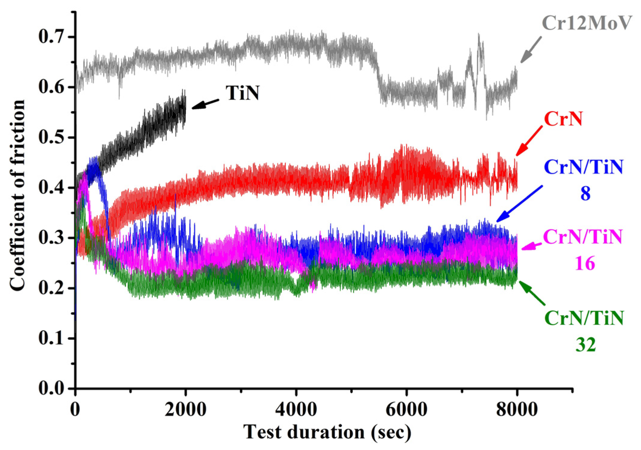
Figure 4 shows the dependence curves of the coefficient of friction (COF) on the sliding time. The tribotechnical characteristics of the investigated coatings are illustrated in
Table 2. The TiN single-layer coating had the highest hardness (31 GPa) and the highest roughness (72 nm) as compared to the other investigated coatings. As a result, the coefficient of friction rapidly increased to about 0.550 during the dry sliding tests of 1700 s. In such a short period of testing compared to other coatings, the wear of this TiN coating surpassed all of the others. It is obvious that intense abrasive wear prevailed for this coating. The hardness of the CrN coating was 24 GPa and the roughness was 50 nm, but the coefficient of friction (0.398) was noticeably lower than for the TiN coating. Thus, the wear of this coating, even with a longer test time (8000 s), was significantly less than for the TiN coating, and the wear parameter was 3.05 × 10
−7 mm
3/N × m. The hardness of all CrN/TiN multi-layer coatings was about the same order of magnitude (26–28 GPa), as were the roughness values (59–66 nm). At the same time, the values of the friction coefficients of multi-layer coatings differed markedly from each other and were in the range of 0.283 to 0.225. However, the COF of these coatings were noticeably lower than for TiN and CrN single-layer coatings. It can be seen (
Figure 4), that all of the tests for multi-layer coatings experienced a running-in period followed by a gradual stabilization in the friction coefficient value. It can be seen that the run-in time for these coatings differed. For 8-layer and 16-layer coatings, the COF reached stable values after about 3500–4000 s. For the 32-layer coating, the run-in time was much less at about 1000 s, and the value of the stable friction coefficient was the smallest among multilayer coatings at 0.225. Thus, an increase in the number of layers to 32 with a corresponding increase in the number of interfacial boundaries between the layers lead to an improvement in the tribological properties. In this case, the resistance to crack propagation at the interface between layers increased [
33]. In addition, a favorable factor for improving the properties of multi-layer coatings was the presence of compressive stresses identified by XRD analysis (
Figure 2).
Synchrotron radiation, due to its high intensity, makes it possible to obtain high resolution data on the structure and phase composition of the surface of a material within a relatively short time. The rapid progress in the technology of new structural and functional materials requires the use of fast and accurate methods to describe the behavior of the materials in laboratory conditions simulating the environmental conditions in which these materials will be exposed, in particular, to elevated temperatures and atmospheric oxygen. The CrN/TiN system is a type of multilayer coating with increased heat resistance that shows promise, in particular, for hardening the surface of structural and functional materials. The results from the synchrotron examination of this type of coating deposited on a WC substrate by X-ray phase analysis at stations No. 2 and No. 6 of the VEPP-3 SR source are presented.
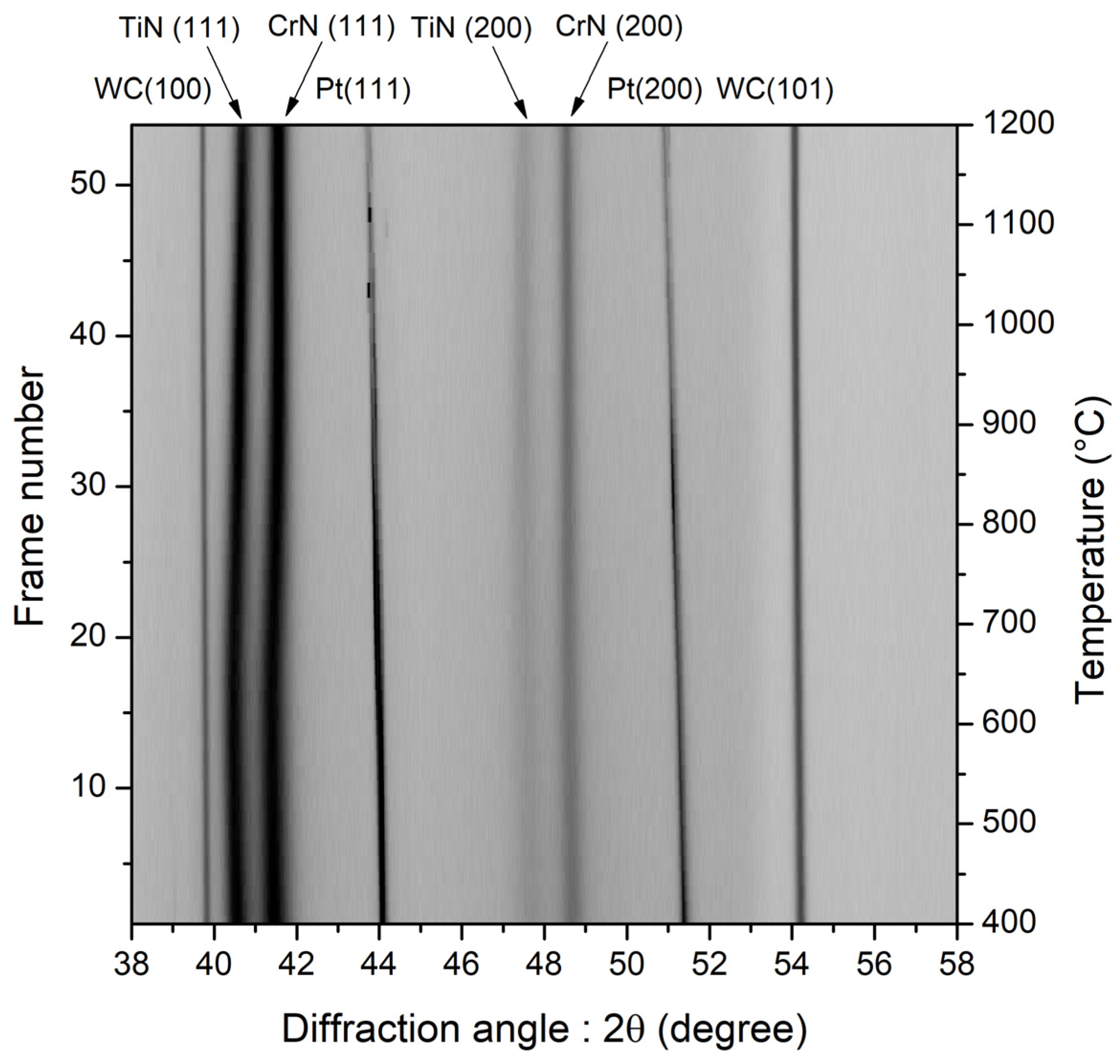
Figure 5 shows the results of the processing of the obtained data arrays: a series of X-ray diffraction patterns of a CrN/TiN sample taken during its heating in air. The patterns are presented as a projection of the reflected X-ray intensity on the plane where the diffraction angle and the temperature are the abscissa and the ordinate, respectively. The light areas indicate low intensity and the dark stripes refer to diffraction maxima; the higher the intensity, the darker the area. There are noticeable reflections of platinum induced by the primary monochromatic beam captured by the sample holder. The temperature range 400–1200 °C was chosen, as up to a temperature of ~400 °C there were no changes in the X-ray diffraction patterns, except for a slight shift of reflections toward smaller angles due to thermal expansion. Changes in the X-ray patterns occurred in the temperature range 700–710 °C. The reflections of the coating ceased to shift toward smaller angles, and even a slight shift to the right can be seen, which indicates a decrease in the interplanar distances and an increase in the intensity of the reflections. The reason for this behavior of the diffraction maxima might be the improvement of the coating structure due to a change in chemical composition, the annealing of defects, the relaxation of microstresses, and the sintering of particles into larger agglomerations. A weak reflection can also be seen at angles 2θ~40.2°; it can be identified as a TiO
2 (101) rutile reflection. As the temperature was increased to 1120–1125 °C, clear reflections of titanium and chromium oxides began to appear. In this case, the reflections of nitrides became less intense, indicating a decrease in the content of the corresponding phases in the sample. Thus, the coating oxidized.
Figure 6 shows a series of X-ray diffraction patterns of a CrN/TiN sample taken during its heating in a vacuum at a residual pressure of 5·10
–3 mbar. They are also presented as projections of the intensity on the “diffraction-angle–temperature” plane. As in
Figure 5, there are noticeable reflections of platinum induced by the primary monochromatic beam captured by the sample holder. As in the case of the sample heated in air, X-ray diffraction patterns taken for temperatures starting at 400 °C are presented. However, in contrast to that case, no changes can be seen for the temperatures up to 690–700 °C, except for a slight shift of reflections toward smaller angles due to thermal expansion. After that, a shift of the nitride reflections to the right occurred, indicating a change in the chemical composition of the coating, a narrowing of the reflections, and an increase in their intensity as a result of the microstress relaxation effect and particle sintering. The phase composition of the coating did not change during the entire time of the measurements. The coating was thermally stable up to temperatures of ~1200 °C.


 ,
, 


