Abstract
The emerging wearable electronics integrated into textiles are posing new challenges both in materials and micro-fabrication strategies to produce textile-based energy storage and power source micro-devices. In this regard, inkjet printing (IJP) offers unique features for rapid prototyping for various thin-film (2D) devices. However, all-inkjet-printed capacitors were very rarely reported in the literature. In this work, we formulated a stable Ti3C2 MXene aqueous ink for inkjet printing current-collector-free electrodes on TPU-coated cotton fabric, together with an innovative inkjet-printable and UV-curable solvent-based electrolyte precursor. The electrolyte was inkjet-printed on the electrode’s surface, and after UV polymerization, a thin and soft gel polymer electrolyte (GPE) was obtained, resulting in an all-inkjet-printed symmetrical capacitor (a-IJPSC). The highest ionic conductivity (0.60 mS/cm) was achieved with 10 wt.% of acrylamide content, and the capacitance retention was investigated both at rest (flat) and under bending conditions. The flat a-IJPSC textile-based device showed the areal capacitance of 0.89 mF/cm2 averaged on 2k cycles. Finally, an array of a-IJPSCs were demonstrated to be feasible as both a textile-based energy storage and micro-power source unit able to power a blue LED for several seconds.
1. Introduction
The rapid development of wearable electronics and the Internet of Things (IoT) with luminescent, sensing and communication capabilities recently motivated the urgent rush toward the development of new compatible energy storage and micro-power source devices [1,2,3]. The relentless work of researchers is leading to a new paradigm in wearable technology, recently named “Textronic” [4]: from the small but rigid electronics attached to garments to more and more miniaturized devices integrated into textiles. In this regard, the new textile-based energy storage and power supply units should combine high efficiency, reliability and adequate energy density combined with the flexibility typical of textiles [5,6,7,8]. Fibrous-shaped (1D) electrodes for both batteries and electrochemical capacitors (ECs) are a popular strategy because of the intrinsic compatibility of yarn-like devices with textiles [9,10,11]. However, the integration of these wire-shaped electrodes into fabrics through conventional industrial manufacturing techniques is still extremely challenging [3,5,12]. In fact, common techniques such as sewing and embroidery cause severe mechanical tensile stresses, friction and deformations to yarns that could likely result in the functional properties degradation. On the other hand, by weaving and knitting, the device must be designed and incorporated during fabric manufacturing, increasing overall difficulties in prototyping. Therefore, new fabrication strategies are needed.
Printing techniques (e.g., screen printing, stencil printing, spray coating, etc.) have been previously demonstrated as an efficient route toward energy storage device integration onto many flexible substrates, including textiles [13,14,15,16,17,18]. In particular, inkjet printing (IJP) offers unique features such as a non-contact and maskless industrially mature additive manufacturing process, as well as its easy scalability and cost-effectiveness [19]. For these reasons, IJP is considered a suitable and promising strategy for the microfabrication of new-generation flexible electronics and devices [19,20,21,22,23,24,25,26]. In recent years, IJP has been successfully employed to produce miniaturized, thin-film flexible energy storage devices [27,28,29,30,31]. ECs uniquely offer superior power density, high reliability, and a long lifecycle, and employ safer electrolytes with respect to toxic or aggressive battery ones. As a consequence, ECs attracted great interest as energy storage and micro-power source devices for textronic applications [14,27,32,33]. Conventionally, ECs relied on carbon-based nanomaterials to produce EC’s electrode patterns, owing to their electrical conductivity and high surface area. However, the current limitation lies in the poor dispersibility of carbon nanostructures in water, requiring significant surfactant loading in the ink formulation or, more often, water replacement with toxic organic solvents.
MXenes are emerging as a new class of conductive 2D materials with remarkable energy storage properties [34]. Ti3C2 MXene is attracting tremendous interest for IJP applications owing to its unique combination of high electrical conductivity and outstanding water dispersibility. Aqueous Ti3C2-based inks were successfully inkjet-printed to produce current-collector-free ECs [32,35,36,37,38,39]. However, in the previous works, only the pure or composite Ti3C2-based electrodes were inkjet-printed, while the electrolyte (typically an acidic or neutral PVA gel aqueous electrolyte) was manually cast on the patterned electrodes. In fact, the IJP of a solid or semi-solid electrolyte is very challenging because of the high viscosity (>>10 mPas) of gel-polymer electrolyte and, more generally, the intrinsic difficult printability of polymers by IJP [40]. As a result, all-inkjet-printed ECs have been very rarely reported. Choi et al. proposed a UV-curable electrolyte composed of an ionic liquid/triacrylate mixture ([BMIM][BF4]/ETPTA) with suitable rheological (13 mPas) and surface tension (22.39 mN/m) for IJP with a commercial desktop printer [28]. On the other hand, Li et al. successfully printed a polyelectrolyte (poly(4-styrenesulfonic acid), PHSS) doped with phosphoric acid and ethylene glycol and achieved a fully IJP graphene EC on Kapton substrate [41].
In this work, we propose an all-inkjet-printed symmetrical Ti3C2 MXene supercapacitor (a-IJPSC) for textile energy storage applications. Both the aqueous Ti3C2 ink and an organic-based electrolyte were inkjet-printed. In particular, the LiCl/EG/AM/MBA electrolyte precursor was inkjet-printed on the conductive Ti3C2-patterned electrodes and in-situ crosslinked by UV irradiation, obtaining a gel polymer electrolyte (GPE) coating. Moreover, a thin TPU thermoplastic sheet was applied to a cotton textile and proposed as an appropriate substrate to achieve reliable and flexible textile-based capacitors. The a-IJPSC devices showed good areal capacitance and capacitance retention under mechanical deformation. Finally, despite a few works that have been previously published for fully inkjet-printed capacitors based on dielectric materials [42,43,44], to the best of our knowledge, electrochemical textile-based a-IJPSCs have never been reported.
2. Materials and Methods
Materials: Commercial grade Ti3AlC2 MAX phase (325 mesh) was purchased from Luoyang Advanced Material Co. LTD (Luoyang, China). Sulphate-nanocellulose (SNC) was bought from Celluforce (Montreal, Quebec, Canada) and photoinitiator (TPO-L) from IGM (Rennes, France). All the other chemicals were obtained from Sigma-Aldrich (München, Germany) and used as received. The thermo-adhesive TPU sheets were kindly provided by Covestro (Leverkusen, Germany), blue SMD LED and a switch button were from MADEIRA.
Ti3AlC2 etching: The Al planes of the Ti3AlC2 MAX phase were etched according to a well-established etching protocol in an HCl/LiF solution (MILD method) [45,46]. First, LiF (15 g) was added to a 9 M (200 mL) HCl solution and stirred for 30 min. Then, the Ti3AlC2 MAX powder (10 g) was gradually added to the HCl/LiF solution to prevent excessive overheating. The etching was carried out at 35 °C for 36 h. The etched MAX was washed multiple times with water by centrifuging at 3500 rpm. Finally, the etched Ti3C2 powder was dried in a vacuum at 60 °C overnight.
Ti3C2Tx and electrolyte inks preparation: The etched Ti3C2 powder (1.5 g), SNC (50 mg), sodium ascorbate (50 mg) and H2O (50 mL) were added to a zirconia jar along with zirconia beads, sealed and wet-milled at 200 rpm for 1 h. The Ti3C2 flakes were further exfoliated and fragmented with a probe sonicator (TOPTIONLAB, Xi’An, China, 1.8 W/L) for 20 min. Finally, 2 mM lithium dodecyl sulphate (LDS) was added, and the ink was centrifuged at 1000 rpm for 10 min to remove very large or non-exfoliated MXene flakes, obtaining the ready-to-use Ti3C2 ink (final concentration of Ti3C2 ~ 1.5 wt.%). The inkjet-printable electrolyte was composed of a 3 M LiCl ethylene glycol (EG) solution to which acrylamide (AM), N,N’-Methylenebisacrylamide (MBA) and photoinitiator (TPO-L) were added in an AM:MBA:TPO-L weight ratio of 20:1:1. The viscous LiCl/EG/AM/MBA electrolyte precursor solution was then diluted with an H2O/2-propanol (IPA) solution to have a 30% v/v final concentration of the electrolyte precursor.
Ti3C2 MXene and electrolyte printing: The as-prepared inks were filled into empty HP45 cartridges and printed with a flatbed Breva (iJet2L, San Vittore Olona, Italy) printer. Patterns were designed with InkScape software (version 1.0.1) and then printed as .png images. The substrates were arranged on the flatbed heated at 50 °C. The electrolyte was cured by UV irradiation (395 nm, 50 W, TAOYUAN ELECTRON, Hong Kong) for a few seconds.
Characterization: Electrode morphology and composition were investigated with Scanning electron microscopy (SEM, EVO 50 EP, Zeiss) and energy dispersive spectroscopy (EDS, INCA x-sight detector, Oxford instruments, Abingdon, UK) operating at 20 kV. The microstructure was investigated through X-ray diffraction (XRD) (model PW1830, Kα1Cu = 1.54058 Å, Philips, Amsterdam, The Netherlands). Dynamic Light Scattering (DLS) was used to investigate the Ti3C2 MXene nanosheet size distribution in the aqueous ink (Zeta sizer Nano, Malvern, UK) at a scattering angle of 173° (backscatter). Ti3C2 ink colloidal stability was assessed by Z-potential analysis (Zeta sizer Nano, Malvern, UK). UV-vis analyses were performed with a V-630 Spectrophotometer (Jasco, Cremella, Italy) equipped with polystyrene cuvette. Electrolyte ink curing was monitored by attenuated total reflection Fourier transform infrared spectroscopy (ATR-FTIR), using a Nicolet 380 spectrometer (Nicolet Instrument Corp., Madison, WI, USA) in the 4000–700 cm−1 range. Surface tension measurements were performed by pendant drop technique with Data Physics OCA 150, equipped with Liquavista Stingray camera. Data were elaborated with OpenDrop software (version 3.3.1). Electrical conductivity of Ti3C2 MXene printed lines was measured both in static and under cyclical deformation conditions (90° bending, 15 rpm) with a custom-built apparatus. The resistance (R) was continuously recorded with a VC650BT SE multimeter (VOLTCRAFT).
Electrochemical characterization: The electrochemical performances of the all-inkjet symmetrical capacitors were evaluated both through cyclic voltammetry and galvanostatic charge-discharge cycles using Admiral Prime (Admiral, Miami, FL, USA) potentiostat/galvanostat and BTS 4000 Neware tester (Neware, Shenzhen, China). Electrochemical impedance spectroscopy (EIS) for ionic conductivity measurements was performed with a Biologic VSP-3e (BioLogic Science Instruments, Grenoble, France) in the 5 MHz-100 mHz frequency range and 15 mV pulse amplitude. A glass fibre separator was immersed in the electrolyte precursor solution, and after excess liquid removal, the gel electrolyte was formed by UV exposure for a few seconds. The ionic conductivity (mS/cm) was calculated according to the equation where l is the gel polymer electrolyte thickness, A the active area and R is the electrolyte resistance extrapolated by the Nyquist plot. EIS measurements on printed devices were performed in the frequency range 100 kHz-100 mHz with an oscillation amplitude of 15 mV at the open-circuit potential. The specific capacitance, energy density and power density of the a-IJPSCs were calculated from both cyclic voltammetry and galvanostatic discharge profile. The capacitance (F) of the printed capacitors was extracted from cyclic voltammetry plots according to the equation where I (mA) is the current, ∆V (V) is the voltage window and v is the scan rate (mV/s). For galvanostatic charge-discharge experiments, the capacitance was computed as [47]. The discharged energy and power were calculated, respectively, according to the equations and where t is the discharge time [39,48].
3. Results
3.1. Ti3C2 and Electrolyte Ink Characterization
Ti3C2 MXenes were employed in this work since they have been widely demonstrated to provide the best electronic conductivity among the solution-processed 2D materials, along with excellent water dispersibility and charge storage properties [49]. Ti3AlC2 powder was successfully etched and exfoliated as confirmed by XRD and SEM (Figures S1 and S2). Owing to its outstanding intrinsic hydrophilicity, stable water Ti3C2 dispersion can be easily prepared by hand-shaking [46] and low-power bath sonication [32,39,48,50]. Multi-layered Ti3C2 particles are well exfoliated in water by shear forces and sonication, but size reduction in the sub-µm scale is also required to avoid easy clogging of the nozzles during IJP. We employed wet-milling and successive probe sonication to both exfoliate and reduce the size of Ti3C2 MXenes, adapting a previously published preparation protocol [51]. We added SNC as a thickener and sodium ascorbate to mitigate Ti3C2 oxidation and prolong ink shelf-life [52]. It is widely known that Ti3C2 MXene storage in water solutions quickly leads to Ti3C2 oxidation from Ti3+ to Ti4+ and TiO2 formation by dissolved oxygen in water and water itself, resulting in electrical conductivity and colloidal stability degradation [53]. Size distribution by the DLS analysis demonstrated the Ti3C2 sheets had the adequate lateral size for IJP (<<1 µm), considering the “rule of thumb” for IJP that requires particles size roughly 2 orders of magnitude lower than nozzle dimension (~30 µm). The average hydrodynamic radius calculated by the DLS analysis can be correlated to the average lateral size <L> of 2D sheets by the equation [54]:
where a is the average hydrodynamic radius. A Z-average of 516.1 nm, corresponding to a <L> ~ 290 nm, was obtained (Figure S3a). Moreover, a Zeta-potential of −41.9 mV (Figure S3b) confirmed the formation of a very stable colloidal suspension. The ink surface tension was then adjusted by adding 2 mM of LDS. Thermal IJP requires surface tension much lower than that of water (72.8 mN/m) [51]. The surface tension values are reported in Figure 1a. Without LDS, the surface tension was just slightly lower than water (65.90 ± 0.84 mN/m), but after the LDS addition, it dropped to 42 ± 1.1 mN/m, which is favourable for thermal IJP. On the other hand, the surface tension of the inkjet-printable electrolyte was as low as 28.5 ± 0.72 mN/m due to the high percentage of organic solvent. In inkjet printing, a high shear rate (>103 s−1) is usually considered as the IJP representative range to evaluate ink viscosity. For the final Ti3C2 MXene ink formulation, viscosity was 2.7 ± 0.09 mPas while for the electrolyte it was 6.5 ± 0.1 mPas (Figure 1b). Both inks showed constant viscosity for a shear rate higher than 102 s−1, representative of Newtonian fluid behaviour. Considering the surface tension and viscosity of the inks and characteristic length as the nozzle diameter (30 µm), the dimensionless Z-number, which is the inverse of the Ohnesorge number, can be calculated according to the equation [55]:
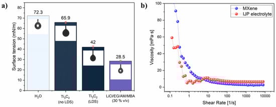
Figure 1.
(a) surface tension values with correspondent pendant drop image; (b) viscosity plot for Ti3C2 MXene ink and LiCl/EG/AM/MBA (30% v/v) electrolyte inks.
The Z number was 11.8 and 4.5 for the Ti3C2 MXene ink and electrolyte ink, respectively, where the optimal printability range is commonly considered to be 1< Z< 10 [51].
3.2. Electrical Conductivity of Ti3C2
Due to their high electrical conductivity, Ti3C2 MXene could serve both as an active material and a current collector. However, reliable conductivity is needed also under deformation. The effect of substrate and overprinting layers (L) on conductivity was investigated by printing Ti3C2 lines of 50 × 2 mm. The Ti3C2 MXene lines were printed both on mylar and the TPU-coated cotton fabric (TPU/Co) (Figure 2a). Ti3C2 MXenes were also printed directly on cotton fabric, but because of the porous and irregular nature of the fabric substrate (Figure S4a), electrical conductivity was even higher than 106 Ohm/cm and extremely sensitive to manual handling. Applying a thin TPU layer flattened the surface (Figure S4b) and solved the issue, achieving a reliable result. The initial linear resistance RL was lower on mylar with respect to TPU/Co for 5 and 10 L (Figure 2a). The RL values were 196 Ohm/cm (5 L) and 106.9 Ohm/cm (10 L) on mylar and 613.8 Ohm/cm (5 L) and 190.5 Ohm/cm (10 L) on TPU/Co, while at 20 L, the two RL were comparable, accounting to 56.4 Ohm/cm and 60 Ohm/cm for the Ti3C2 printed on mylar and TPU/Co, respectively. The higher resistance of printed lines on TPU/Co for a low number of overprinting layers was very likely due to the much higher roughness and irregular surface of the TPU/Co substrate compared to the perfectly flat and smooth mylar foil. As the number of layers increased, the Ti3C2 nanosheets filled the valleys of the TPU/Co textured surface, resulting in a more flat surface. The overall levelling to an almost flat surface was reached after 20 L. By further increasing the overprinting layers on TPU/Co to 30 L, the RL just slightly decreased at 46 Ohm/cm. The electrical resistance was monitored under flat (180°) and cyclical bending (90°) conditions. When the Ti3C2 were printed on mylar, the average resistance normalized on the initial one (R/R0) on 1000 bending cycles always approached ~1, namely 0.91 ± 0.07, 0.95 ± 0.05 and 1.15 ± 0.07 for 5, 10 and 20 L, respectively (Figure 2b). Noteworthy, the bending test was performed by placing the MXene pattern on the backside in order to induce tensile stress on the Ti3C2 layer by bending. When 5 and 10 L Ti3C2 were printed on TPU/Co, the average R/R0 values were 0.92 ± 0.05 and 1.04 ± 0.03, respectively, and for L > 10, the R/R0 trend was extremely smooth, representative of excellent conductivity retention even after 1000 bending cycles. In fact, the average R/R0 values were 1.02 ± 0.03 (20 L) and 1.02 ± 0.02 (30 L). The 30 L samples were also tested by placing them with the Ti3C2 line upper side to induce compression stress on the printed pattern upon cycling. Again, remarkable conductivity retention was demonstrated by the ultra-flat R/R0 and average value of 1.05 ± 0.02.
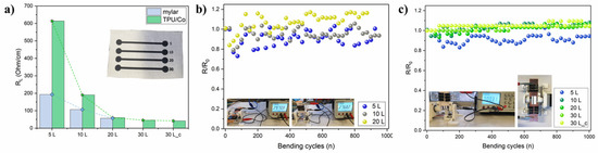
Figure 2.
(a) initial RL of the Ti3C2 lines (50 × 2 mm) according to the overprinting layers on mylar film and TPU/Co (real picture in inset figure; (b) linear resistance retention upon bending cycles at 90° and 15 rpm for the printed Ti3C2 lines on mylar; (c) same on TPU/Co substrate. The real pictures of the test are reported as inset figures.
The SEM images of the Ti3C2 printed lines are reported in Figure 3. Comparing the 5 L (Figure 3a) and 20 L (Figure 3b) Ti3C2 lines, SEM analyses confirmed that a minimum of 20 L was needed in order to achieve a homogeneous and relatively thick coating while at 5 L the substrate is still visible, resulting in high RL. The Ti3C2 layer was composed of a compact film of MXene sheets (Figure 3c,d) with a very uniform distribution as shown by the EDS map in Figure 3e. In general, the SEM images revealed well-defined lines, without evident overspray due to excessive satellite-drop formation during jetting, demonstrating a good printability of the ink. When the Ti3C2 line printed on TPU/Co (30 L) was bent, multiple cracks formed (Figure 3f), even though the electrical conductivity results suggested these cracks didn’t affect the bulk conductivity, and an excellent percolation of the Ti3C2 was maintained.
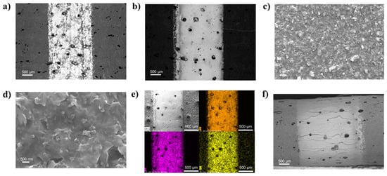
Figure 3.
(a,b) SEM images of the Ti3C2 MXene printed lines on TPU/Co substrates at 5 and 20 L, respectively; (c,d) detail of the morphology of the 20 L surface; (e) EDS map (Ti, F, Cl) of the 20 L sample; (f) images in BSD mode of the 30 L line on TPU/Co in a bent state, with a focus on the curvature area.
3.3. Inkjet Printable Electrolyte
Electrolyte printing is definitely the main bottleneck in the development of miniaturized and flexible electrochemical capacitors and batteries for wearable and textronic applications. Liquid electrolytes cannot be employed because of technical difficulties with their insulation and leakage issues. On the other hand, gel polymer electrolytes are very viscous and not compatible with IJP technology. We formulated here a simple UV-curable ink electrolyte based on EG since it can easily dissolve high concentrations of LiCl, AM and TPO-L. The effect on the ionic conductivity of the AM content was investigated through EIS analysis (Figure 4). Nyquist plots revealed that R2 (sometimes termed also as the charge transfer resistance Rct) increased by increasing the AM content from 10 wt.% to 30 wt.% In particular, at 10 wt.%, the ionic conductivity dropped from 2.03 mS/cm before UV curing to 0.60 mS/cm after the UV exposure and crosslinking. The values of R2 and σ are given in Table 1. The 10 wt.% AM loading was selected because of the highest ionic conductivity, and even at this low loading, a transparent soft GPE was formed (Figure S5).
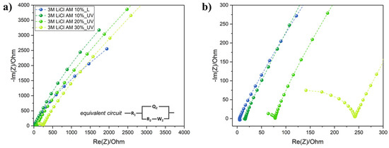
Figure 4.
(a) Nyquist plots of GPE with increasing AM content, with the equivalent circuit used for R2 extrapolation in the inset figure; (b) focus on low real impedance values of the Nyquist plots.

Table 1.
R2 and ionic conductivity values calculated.
The viscous LiCl/EG/AM/MBA electrolyte was diluted with an IPA/H2O mixture to lower the viscosity to suitable values for IJP, and the electrolyte polymerization was monitored by ATR-FTIR and, in particular, the effect of heating time at 50 °C on IPA and H2O evaporation was investigated (Figure 5a). The -CH stretching vibration of IPA was well visible at 2970 cm−1 (Figure 5b) and vibrated at different frequencies than the EG one. After just 1 min at 50 °C before UV-curing, the -CH stretching band of IPA was negligible, suggesting the fast evaporation of the solvent and the -CH2 symmetric stretching bands for t > 1 min resembled the non-diluted electrolyte. Moreover, by increasing the drying time, the broad -OH peak absorbance red shifted, and after 5 min it was roughly centered at the same frequency as the UV-cured and non-diluted LiCl EG/AM/MBA gel. Coherently with increasing the drying time, the -C=O peaks stiffened while -C=C absorbance reduced (Figure 5c) as symptomatic of higher polymerization efficiency due to excess solvent removal. This was confirmed also by the formation of a soft but solid gel only for t > 1 min while UV-curing of the electrolyte precursor within 1 min drying resulted in a liquid-like gel with poor mechanical properties. Noteworthy, the -C-C skeletal vibration at 950 cm−1 (Figure 5d) was almost null for t > 2 min. As a consequence, a drying step of ~5 min was always performed before UV-curing of the inkjet-printed electrolyte.
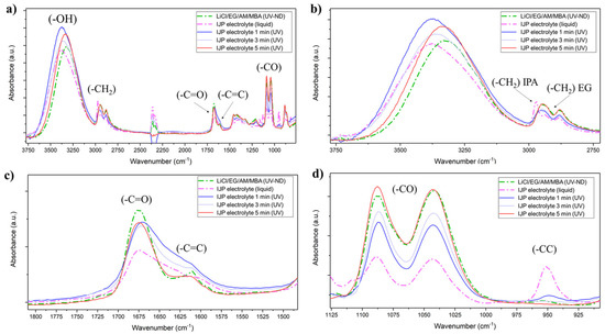
Figure 5.
(a) ATR-FTIR of the non-diluted (ND) LiCl/EG/AM/MBA electrolyte precursor and inkjet-printable electrolyte in liquid and polymerized state after 1, 3 and 5 min of excess solvent evaporation; (b) focus on the absorbance spectra in the -OH and -CH2 absorbance region; (c) focus on the -C=O and -C=C region; (d) focus on the -CC region.
3.4. Textile-Based All-Inkjet Printed Ti3C2 MXene Symmetrical Capacitors (a-IJPSCs)
A schematic representation of the Ti3C2 a-IJPSC preparation is given in Figure 6a while some real pictures of the printed devices are given in Figure S6. Ti3C2 MXene and electrolyte precursor inks were consecutively inkjet-printed, and the electrolyte was then cured by UV illumination for a few seconds after 5 min drying at 50 °C, obtaining a thin GPE coating. The flexible textile-based a-IJPSC devices were then produced. Figure 6b shows the Ti3C2 electrodes inkjet printed with the conventional interdigitated configuration. The interdigitated Ti3C2 lines were typically printed at 1 mm width and (if not differently specified) 0.6 mm inter-electrode spacing. The SEM images of the inkjet-printed Ti3C2 electrodes show that the Ti3C2 ink could be jetted with good quality without spraying or satellite-drop formation. After the electrolyte printing and UV curing, the Ti3C2 patterned electrodes were clearly covered by a uniform solid layer that made the underlying Ti3C2 lines barely visible (Figure 6c).
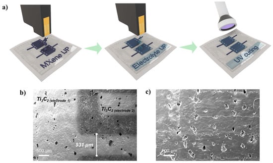
Figure 6.
(a) schematic representation of the a-IJPSC on TPU/Co substrate preparation; (b,c) SEM images of the Ti3C2 MXene interdigitated electrodes, respectively, with and without the GPE coating. For this sample, a 1 mm inter-electrode distance was used.
The effect of the electrolyte overprinting layers (i.e., the total electrolyte amount) was investigated by EIS. Two Ti3C2 electrodes with interdigitated configuration were printed (20 L) on the TPU/Co textile, and 5 to 30 layers of electrolyte precursor were consecutively printed on top. Nyquist plots (Figure 7a,b) clearly showed that increasing the electrolyte overprinting layers on the Ti3C2 electrodes resulted in a consistent shift of the equivalent series resistance (RESR) to lower values. Since both the pattern, Ti3C2 MXene overprinting layers and inter-electrode distance (0.6 mm) were the same, the lower RESR could be attributed to the real impedance decreasing the GPE only. In fact, the RESR drastically decreased from 61 kOhm to 6.09 kOhm and 2 kOhm for 10, 20 and 30 L respectively. Even after 30 L, the RESR was close but higher (~ 2 times) than the “flooded” conditions obtained by manually casting ~ 0.3 mL of electrolyte precursor solution with a micropipette. All the subsequent results were obtained by fixing the electrolyte overprinting layers to 30.
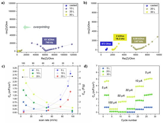
Figure 7.
(a,b) Nyquist plots for the a-IJPSC devices with different electrolyte overprinting numbers; (c) areal and specific capacitance at increasing scan rates (5, 10, 25, 50, 100 mV/s) in the 0–0.8 V range (mass for Csp calculation was considered as Ti3C2 mass only, area as the whole device surface); (d) areal capacitance obtained by galvanostatic charge-discharge cycles at different currents.
Since by increasing the number of Ti3C2 layers the overall material loading was increased, the total Ti3C2 weight per printed layer normalized on the area was estimated by weighting punched samples of Ti3C2 MXene printed up to 30 layers (Figure S7). The results indicated that an average of 23 µg/cm2 of Ti3C2 MXene were printed at each layer. The mass estimation allowed to normalize on both the active mass and active area (i.e., electrodes only) the capacitance values obtained through cyclic voltammetry at different scan rates in the 0–0.8 V range (Figure 7c). The rectangular-like shape of cyclic voltammetry (Figure S8) is indicative of double-layer capacitance as typically observed for Ti3C2 MXene in LiCl and other neutral electrolyte solutions [56,57,58], contrary to the prominent pseudocapacitive behaviour that arises in acidic electrolyte because of H+ intercalation [59,60,61]. However, it is noteworthy that symmetric capacitors typically suffer from an asymmetrical charge accumulation on the two electrodes that is the main bottleneck in their limited working potential window and relatively low capacitance. When specific capacitance Csp is considered, the 10 L showed the highest values, up to 11.3 F/g at 5 mV/s and 20 L the lowest (7.1 F/g), but in terms of areal capacitance Ca, a coherent trend was found by increasing Ti3C2 printing layers. The results could be reasonably explained by assuming that by increasing the Ti3C2 layers, the mass increased, as well as the electrode thickness and, as a consequence, deeper Ti3C2 MXene sheets became less and less accessible to the electrolyte. The bottom Ti3C2 layer could then provide a constant electrical conductivity, serving as the true current collector. However, considering the ultra-low amount of material-deposited fabrication (roughly a total of 0.014 mg for a 1 cm2 device), the areal capacitance is a much more indicative benchmark when dealing with thin-film devices. At last, the rate capability was also investigated by galvanostatic charge-discharge cycles at different currents. The correspondent areal capacitance values (Figure 7d) were in good accordance with the cyclic voltammetry results and confirmed the overall better performances of the printed device by increasing the Ti3C2 printed layers.
A custom-built apparatus was employed for the investigation of the working-under-deformation capacitance retention. In fact, textile-based capacitor devices should be inherently flexible and capable of providing constant energy storage both at rest and under various deformation conditions. A 1 cm2 area device (0.6 mm inter-electrode distance) was galvanostatically cycled at 5 µA during cyclical bending from 180° to 90° at 15 rpm. The areal capacitance almost linearly decreased during cycling, but after 13k bending cycles (140 charge-discharge cycles), the capacitance retention C/C0 was still considerably high at 61.7% (Figure 8a). The long cycling test was performed at a flat configuration at 50 µA in the 0–0.8 V range (Figure 8b). Averaging on 2k cycles, the Ca was 0.86 mF/cm2, the coulombic efficiency approached 99.2% and the areal energy Ea and power Pa were respectively 0.08 µWh/cm2 and 20 µW/cm2. The C/C0 at 140 cycles was 94% and after 1k cycles it was 68%, which was considerably higher than the same a-IJPSC bent during cycling, suggesting that the GPE may be damaged upon multiple mechanical deformations or the Ti3C2 electrode/GPE interface may be degraded. A deeper investigation into the lower capacity retention during bending will be addressed in future work. In general, the Ca, Ea and Pa were ~101−2 lower compared to previous seminal works on Ti3C2 MXene inkjet-printed capacitors but employing manually cast, aqueous gel-polymer acidic electrolytes, non-aqueous ink or additives, such as PEDOT:PSS [32,39,48]. A comparison of the performances of our textile-based a-IJPSC with other reference works is provided in Table 2.
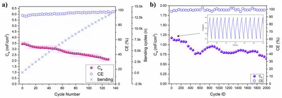
Figure 8.
(a) Ca and coulombic efficiency (CE) with respect to galvanostatic charge-discharge (5 µA) and bending cycles; (b) Ca and CE of the long-cycling test performed with a galvanostatic charge-discharge current of 50 µA at rest (flat) condition (Ti3C2 20 L and electrolyte precursor 30 L). The voltage-time profile of the first few cycles is reported as the inset figure.
Table 2.
Comparison of Ca, Ea and Pa with respect to similar reference literature works. The reported values for this work are related to the long cycling test of Figure 8b.
A great advantage of our a-IJPSC production method is the countless number of possible miniaturized designs, including parallel and series connections to increase the overall areal capacitance (i.e., energy) or voltage (i.e., power). In Figure 9a, an example of parallel and series devices connection is reported. The cyclic voltammetry coherently shows that by connecting devices in parallel (up to three), the current in cyclic voltammetry plots increased along with the equivalent capacitance () while in a series connection, the individual textile-based capacitor voltage could be summed up to 2.4 V by decreasing the equivalent capacitance from 3.4 mF (1 s) to 1.1 mF (3 s), reminding that the Ceq for series capacitors is .
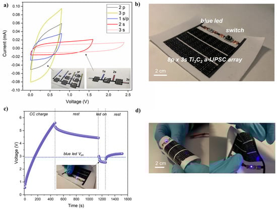
Figure 9.
(a) cyclic voltammetry (5 mV/s) of series and parallel connections (up to 3) of Ti3C2 a-IJPSC; (b) picture of the textile-based 24-device a-IJPSC on TPU/Co and electronic circuit equipped with a blue LED and button switch; (c) voltage profile recorded during galvanostatic charge (50 µA), rest step, LED powering and final rest; (d) pictures of the a-IJPSC array powering the blue LED while subjected to various deformations.
In textronic applications, the meaning of textile energy storage units could be to store energy and release it on demand to power other textile-based units, such as sensors, communications, luminescent devices, etc. As a demonstration of the feasibility of our Ti3C2 a-IJPSC for textronic applications, an array of 24 individual capacitors (total area 32 cm2) were inkjet-printed on TPU/Co substrate and integrated in a simple electronic circuit with a blue LED (Von > 2.6 V) and a switch button, connected to the Ti3C2 a-IJPSC array working as a power source unit. The image of the circuit is reported in Figure 9b. The array was galvanostatically charged up to 5.6 V, and after 5 min of rest, the blue LED was powered on for 100 s by pushing the switch button, during which the voltage dropped to ~2.6 V (Figure 9c). Noteworthy, the blue LED could be lighted up also during various bending and deformations, as shown in Figure 9d.
4. Conclusions
In this work, we propose an easy strategy to obtain textile-based all-inkjet-printed symmetrical capacitors based on Ti3C2 MXene electrodes and a novel gel polymer electrolyte formulation. A stable aqueous Ti3C2 ink as well as UV-curable electrolyte precursor ink was formulated with good printability properties suitable for thermal inkjet printing. In particular, the printable electrolyte precursor ink allowed us to obtain for the first time an all-inkjet-printed capacitor on TPU-coated cotton fabric, allowing definitive control on patterning with respect to the manual-casting process of a gel-polymer electrolyte commonly employed in the literature. By optimizing the printing process, as well as the Ti3C2 MXene and the number of electrolyte overprinting layers, acceptable areal capacitance, energy and power were achieved. By printing an array of a-IJPSCs with parallel and series connections, a device was obtained on TPU/Co substrate, working as energy storage and micro-power source able to power a blue LED for several seconds and demonstrating its applicability for textile energy storage application. In principle, the proposed here methods and, in particular, UV-curable electrolyte, could be employed for the production of both symmetric and asymmetric all-inkjet-printed electrochemical capacitors based on a variety of popular active materials as 1D/2D/3D carbon nanostructures, other MXenes, conductive polymers, etc. We strongly believe this work could pave the way for the development of high-performance textile-based energy storage by inkjet-printing processing.
Supplementary Materials
The following supporting information can be downloaded at: https://www.mdpi.com/article/10.3390/coatings13020230/s1. Figure S1: XRD patterns for the Ti3AlC2 MAX and the etched Ti3C2 MXene after 36 h etching; Figure S2: SEM images of the Ti3AlC2 MAX (a) and multilayer etched Ti3C2 MXene (b). In (c) and (d) the EDS spectra for the MAX and etched multilayer MXene powder are provided; Figure S3: DLS (a) and Z-potential (b) file report of the Ti3C2 ink; Figure S4: EDS image of the Ti3C2 MXene printed on the neat cotton fabric (a) and TPU-coated fabric (b); Figure S5: (a) a glass fibre separator was used as support matrix for ionic conductivity measurement; (b) the separator was soaked in the electrolyte precursor and then UV-cured for few seconds, a soft and flexible GPE was obtained; (c) when the electrolyte precursor was casted in a mould and then UV-cured, a free-standing transparent GPE was obtained; Figure S6: Real picture of a 1.5 cm2 a-IJPSC produced with 0.6 mm interelectrode spacing, Ti3C2 20 L and electrolyte 30 L. The UV-cured GPE is clearly visible as a reflecting transparent coating on top; Figure S7: The printed Ti3C2 mass/layer normalized on printed area; Figure S8: Cyclic voltammetries at 5 mV/s for a-IJPSC devices printed on TPU/Co with increasing Ti3C2 overprinting layers and 30 L of electrolyte precursor printing. References [42,58,59,60,61,62] are cited in the supplementary materials.
Author Contributions
Conceptualization, E.G.; methodology and investigation, E.G., F.L., L.B. and P.V.; data curation, E.G.; writing—original draft preparation, E.G.; writing—review and editing, F.L., L.B., P.V. and L.M.; supervision, E.G. and L.M. All authors have read and agreed to the published version of the manuscript.
Funding
This research received no external funding.
Institutional Review Board Statement
Not applicable.
Informed Consent Statement
Not applicable.
Data Availability Statement
Data are contained within the article.
Acknowledgments
The authors thank Lorenzo Bonetti and Luigi De Nardo for the rheology measurements.
Conflicts of Interest
The authors declare no conflict of interest.
References
- Jost, K.; Dion, G.; Gogotsi, Y. Textile Energy Storage in Perspective. J. Mater. Chem. A 2014, 2, 10776–10787. [Google Scholar] [CrossRef]
- Wang, L.; Fu, X.; He, J.; Shi, X.; Chen, T.; Chen, P.; Wang, B.; Peng, H. Application Challenges in Fiber and Textile Electronics. Adv. Mater. 2020, 32, 1901971. [Google Scholar] [CrossRef] [PubMed]
- Sumboja, A.; Liu, J.; Zheng, W.G.; Zong, Y.; Zhang, H.; Liu, Z. Electrochemical Energy Storage Devices for Wearable Technology: A Rationale for Materials Selection and Cell Design. Chem. Soc. Rev. 2018, 47, 5919–5945. [Google Scholar] [CrossRef] [PubMed]
- Choudhry, N.A.; Arnold, L.; Rasheed, A.; Khan, I.A.; Wang, L. Textronics—A Review of Textile-Based Wearable Electronics. Adv. Eng. Mater. 2021, 23, 2100469. [Google Scholar] [CrossRef]
- Liu, Z.; Mo, F.; Li, H.; Zhu, M.; Wang, Z.; Liang, G.; Zhi, C. Advances in Flexible and Wearable Energy-Storage Textiles. Small Methods 2018, 2, 1800124. [Google Scholar] [CrossRef]
- Zhai, S.; Karahan, H.E.; Wei, L.; Qian, Q.; Harris, A.T.; Minett, A.I.; Ramakrishna, S.; Ng, A.K.; Chen, Y. Textile Energy Storage: Structural Design Concepts, Material Selection and Future Perspectives. Energy Storage Mater. 2016, 3, 123–139. [Google Scholar] [CrossRef]
- Cheng, H.; Li, Q.; Zhu, L.; Chen, S. Graphene Fiber-Based Wearable Supercapacitors: Recent Advances in Design, Construction, and Application. Small Methods 2021, 5, 2100502. [Google Scholar] [CrossRef]
- Huang, Q.; Wang, D.; Zheng, Z. Textile-Based Electrochemical Energy Storage Devices. Adv. Energy Mater. 2016, 6, 1600783. [Google Scholar] [CrossRef]
- Xi, Z.; Zhang, X.; Ma, Y.; Zhou, C.; Yang, J.; Wu, Y.; Li, X.; Luo, Y.; Chen, D. Recent Progress in Flexible Fibrous Batteries. ChemElectroChem 2018, 5, 3127–3137. [Google Scholar] [CrossRef]
- Lu, L.; Hu, Y.; Dai, K. The Advance of Fiber-Shaped Lithium Ion Batteries. Mater. Today Chem. 2017, 5, 24–33. [Google Scholar] [CrossRef]
- Sun, H.; Zhang, Y.; Zhang, J.; Sun, X.; Peng, H. Energy Harvesting and Storage in 1D Devices. Nat. Rev. Mater. 2017, 2, 17023. [Google Scholar] [CrossRef]
- Mo, F.; Liang, G.; Huang, Z.; Li, H.; Wang, D.; Zhi, C. An Overview of Fiber-Shaped Batteries with a Focus on Multifunctionality, Scalability, and Technical Difficulties. Adv. Mater. 2020, 32, 1902151. [Google Scholar] [CrossRef]
- Choi, K.-H.; Ahn, D.B.; Lee, S.-Y. Current Status and Challenges in Printed Batteries: Toward Form Factor-Free, Monolithic Integrated Power Sources. ACS Energy Lett. 2018, 3, 220–236. [Google Scholar] [CrossRef]
- Guo, H.; Jiang, Z.; Ren, D.; Li, S.; Wang, J.; Cai, X.; Zhang, D.; Guo, Q.; Xiao, J.; Yang, J. High-Performance Flexible Micro-Supercapacitors Printed on Textiles for Powering Wearable Electronics. ChemElectroChem 2021, 8, 1574–1579. [Google Scholar] [CrossRef]
- Kumar, R.; Shin, J.; Yin, L.; You, J.-M.; Meng, Y.S.; Wang, J. All-Printed, Stretchable Zn-Ag2O Rechargeable Battery via Hyperelastic Binder for Self-Powering Wearable Electronics. Adv. Energy Mater. 2017, 7, 1602096. [Google Scholar] [CrossRef]
- Zhang, H.; Qiao, Y.; Lu, Z. Fully Printed Ultraflexible Supercapacitor Supported by a Single-Textile Substrate. ACS Appl. Mater. Interfaces 2016, 8, 32317–32323. [Google Scholar] [CrossRef]
- Kim, S.-H.; Choi, K.-H.; Cho, S.-J.; Choi, S.; Park, S.; Lee, S.-Y. Printable Solid-State Lithium-Ion Batteries: A New Route toward Shape-Conformable Power Sources with Aesthetic Versatility for Flexible Electronics. Nano Lett. 2015, 15, 5168–5177. [Google Scholar] [CrossRef]
- Singh, N.; Galande, C.; Miranda, A.; Mathkar, A.; Gao, W.; Reddy, A.L.M.; Vlad, A.; Ajayan, P.M. Paintable Battery. Sci. Rep. 2012, 2, 481. [Google Scholar] [CrossRef]
- Singh, M.; Haverinen, H.M.; Dhagat, P.; Jabbour, G.E. Inkjet Printing—Process and Its Applications. Adv. Mater. 2010, 22, 673–685. [Google Scholar] [CrossRef]
- Gao, M.; Li, L.; Song, Y. Inkjet Printing Wearable Electronic Devices. J. Mater. Chem. C 2017, 5, 2971–2993. [Google Scholar] [CrossRef]
- Yin, Z.; Huang, Y.; Bu, N.; Wang, X.; Xiong, Y. Inkjet Printing for Flexible Electronics: Materials, Processes and Equipments. Chin. Sci. Bull. 2010, 55, 3383–3407. [Google Scholar] [CrossRef]
- Mattana, G.; Loi, A.; Woytasik, M.; Barbaro, M.; Noël, V.; Piro, B. Inkjet-Printing: A New Fabrication Technology for Organic Transistors. Adv. Mater. Technol. 2017, 2, 1700063. [Google Scholar] [CrossRef]
- Karim, N.; Afroj, S.; Tan, S.; Novoselov, K.S.; Yeates, S.G. All Inkjet-Printed Graphene-Silver Composite Ink on Textiles for Highly Conductive Wearable Electronics Applications. Sci. Rep. 2019, 9, 8035. [Google Scholar] [CrossRef] [PubMed]
- Lo, L.-W.; Shi, H.; Wan, H.; Xu, Z.; Tan, X.; Wang, C. Inkjet-Printed Soft Resistive Pressure Sensor Patch for Wearable Electronics Applications. Adv. Mater. Technol. 2020, 5, 1900717. [Google Scholar] [CrossRef]
- Lo, L.-W.; Zhao, J.; Wan, H.; Wang, Y.; Chakrabartty, S.; Wang, C. An Inkjet-Printed PEDOT:PSS-Based Stretchable Conductor for Wearable Health Monitoring Device Applications. ACS Appl. Mater. Interfaces 2021, 13, 21693–21702. [Google Scholar] [CrossRef]
- Huang, T.-T.; Wu, W. Inkjet-Printed Wearable Nanosystems for Self-Powered Technologies. Adv. Mater. Interfaces 2020, 7, 2000015. [Google Scholar] [CrossRef]
- Sajedi-Moghaddam, A.; Rahmanian, E.; Naseri, N. Inkjet-Printing Technology for Supercapacitor Application: Current State and Perspectives. ACS Appl. Mater. Interfaces 2020, 12, 34487–34504. [Google Scholar] [CrossRef]
- Choi, K.-H.; Yoo, J.; Lee, C.K.; Lee, S.-Y. All-Inkjet-Printed, Solid-State Flexible Supercapacitors on Paper. Energy Environ. Sci. 2016, 9, 2812–2821. [Google Scholar] [CrossRef]
- Deiner, L.J.; Reitz, T.L. Inkjet and Aerosol Jet Printing of Electrochemical Devices for Energy Conversion and Storage. Adv. Eng. Mater. 2017, 19, 1600878. [Google Scholar] [CrossRef]
- Huang, T.-T.; Wu, W. Scalable Nanomanufacturing of Inkjet-Printed Wearable Energy Storage Devices. J. Mater. Chem. A 2019, 7, 23280–23300. [Google Scholar] [CrossRef]
- Liu, W.; Lu, C.; Li, H.; Tay, R.Y.; Sun, L.; Wang, X.; Chow, W.L.; Wang, X.; Tay, B.K.; Chen, Z.; et al. Paper-Based All-Solid-State Flexible Micro-Supercapacitors with Ultra-High Rate and Rapid Frequency Response Capabilities. J. Mater. Chem. A 2016, 4, 3754–3764. [Google Scholar] [CrossRef]
- Uzun, S.; Schelling, M.; Hantanasirisakul, K.; Mathis, T.S.; Askeland, R.; Dion, G.; Gogotsi, Y. Additive-Free Aqueous MXene Inks for Thermal Inkjet Printing on Textiles. Small 2021, 17, 2006376. [Google Scholar] [CrossRef]
- Chen, P.; Chen, H.; Qiu, J.; Zhou, C. Inkjet Printing of Single-Walled Carbon Nanotube/RuO2 Nanowire Supercapacitors on Cloth Fabrics and Flexible Substrates. Nano Res. 2010, 3, 594–603. [Google Scholar] [CrossRef]
- Gogotsi, Y.; Anasori, B. The Rise of MXenes. ACS Nano 2019, 13, 8491–8494. [Google Scholar] [CrossRef]
- Wu, C.-W.; Unnikrishnan, B.; Chen, I.-W.P.; Harroun, S.G.; Chang, H.-T.; Huang, C.-C. Excellent Oxidation Resistive MXene Aqueous Ink for Micro-Supercapacitor Application. Energy Storage Mater. 2020, 25, 563–571. [Google Scholar] [CrossRef]
- Wen, D.; Ying, G.; Liu, L.; Li, Y.; Sun, C.; Hu, C.; Zhao, Y.; Ji, Z.; Zhang, J.; Wang, X. Direct Inkjet Printing of Flexible MXene/Graphene Composite Films for Supercapacitor Electrodes. J. Alloys Compd. 2022, 900, 163436. [Google Scholar] [CrossRef]
- Wen, D.; Wang, X.; Liu, L.; Hu, C.; Sun, C.; Wu, Y.; Zhao, Y.; Zhang, J.; Liu, X.; Ying, G. Inkjet Printing Transparent and Conductive MXene (Ti3C2Tx) Films: A Strategy for Flexible Energy Storage Devices. ACS Appl. Mater. Interfaces 2021, 13, 17766–17780. [Google Scholar] [CrossRef]
- Wen, D.; Ying, G.; Liu, L.; Sun, C.; Li, Y.; Zhao, Y.; Ji, Z.; Wu, Y.; Zhang, J.; Zhang, J.; et al. Flexible and High-Performance MXene/MnO2 Film Electrodes Fabricated by Inkjet Printing: Toward a New Generation Supercapacitive Application. Adv. Mater. Interfaces 2021, 8, 2101453. [Google Scholar] [CrossRef]
- Ma, J.; Zheng, S.; Cao, Y.; Zhu, Y.; Das, P.; Wang, H.; Liu, Y.; Wang, J.; Chi, L.; Liu, S.F.; et al. Aqueous MXene/PH1000 Hybrid Inks for Inkjet-Printing Micro-Supercapacitors with Unprecedented Volumetric Capacitance and Modular Self-Powered Microelectronics. Adv. Energy Mater. 2021, 11, 2100746. [Google Scholar] [CrossRef]
- de Gans, B.-J.; Duineveld, P.C.; Schubert, U.S. Inkjet Printing of Polymers: State of the Art and Future Developments. Adv. Mater. 2004, 16, 203–213. [Google Scholar] [CrossRef]
- Li, J.; Sollami Delekta, S.; Zhang, P.; Yang, S.; Lohe, M.R.; Zhuang, X.; Feng, X.; Östling, M. Scalable Fabrication and Integration of Graphene Microsupercapacitors through Full Inkjet Printing. ACS Nano 2017, 11, 8249–8256. [Google Scholar] [CrossRef] [PubMed]
- Lipatov, A.; Alhabeb, M.; Lukatskaya, M.R.; Boson, A.; Gogotsi, Y.; Sinitskii, A. Effect of Synthesis on Quality, Electronic Properties and Environmental Stability of Individual Monolayer Ti3C2 MXene Flakes. Adv. Electron. Mater. 2016, 2, 1600255. [Google Scholar] [CrossRef]
- Alhabeb, M.; Maleski, K.; Anasori, B.; Lelyukh, P.; Clark, L.; Sin, S.; Gogotsi, Y. Guidelines for Synthesis and Processing of Two-Dimensional Titanium Carbide (Ti3C2Tx MXene). Chem. Mater. 2017, 29, 7633–7644. [Google Scholar] [CrossRef]
- Mathis, T.S.; Kurra, N.; Wang, X.; Pinto, D.; Simon, P.; Gogotsi, Y. Energy Storage Data Reporting in Perspective—Guidelines for Interpreting the Performance of Electrochemical Energy Storage Systems. Adv. Energy Mater. 2019, 9, 1902007. [Google Scholar] [CrossRef]
- Zhang, C.; McKeon, L.; Kremer, M.P.; Park, S.-H.; Ronan, O.; Seral-Ascaso, A.; Barwich, S.; Coileáin, C.Ó.; McEvoy, N.; Nerl, H.C.; et al. Additive-Free MXene Inks and Direct Printing of Micro-Supercapacitors. Nat. Commun. 2019, 10, 1795. [Google Scholar] [CrossRef]
- Seyedin, S.; Zhang, J.; Usman, K.A.S.; Qin, S.; Glushenkov, A.M.; Yanza, E.R.S.; Jones, R.T.; Razal, J.M. Facile Solution Processing of Stable MXene Dispersions towards Conductive Composite Fibers. Glob. Chall. 2019, 3, 1900037. [Google Scholar] [CrossRef]
- Viviani, P.; Gibertini, E.; Iervolino, F.; Levi, M.; Magagnin, L. Carbon Additive Effect on the Electrochemical Performances of Inkjet Printed Thin-Film Li4Ti5O12 Electrodes. J. Manuf. Process. 2021, 72, 411–418. [Google Scholar] [CrossRef]
- Zhao, X.; Vashisth, A.; Prehn, E.; Sun, W.; Shah, S.A.; Habib, T.; Chen, Y.; Tan, Z.; Lutkenhaus, J.L.; Radovic, M.; et al. Antioxidants Unlock Shelf-Stable Ti3C2Tx (MXene) Nanosheet Dispersions. Matter 2019, 1, 513–526. [Google Scholar] [CrossRef]
- Wu, T.; Kent, P.R.C.; Gogotsi, Y.; Jiang, D. How Water Attacks MXene. Chem. Mater. 2022, 34, 4975–4982. [Google Scholar] [CrossRef]
- Lotya, M.; Rakovich, A.; Donegan, J.F.; Coleman, J.N. Measuring the Lateral Size of Liquid-Exfoliated Nanosheets with Dynamic Light Scattering. Nanotechnology 2013, 24, 265703. [Google Scholar] [CrossRef]
- Fromm, J.E. Numerical Calculation of the Fluid Dynamics of Drop-on-Demand Jets. IBM J. Res. Dev. 1984, 28, 322–333. [Google Scholar] [CrossRef]
- Zang, X.; Wang, J.; Qin, Y.; Wang, T.; He, C.; Shao, Q.; Zhu, H.; Cao, N. Enhancing Capacitance Performance of Ti3C2Tx MXene as Electrode Materials of Supercapacitor: From Controlled Preparation to Composite Structure Construction. Nano-Micro Lett. 2020, 12, 77. [Google Scholar] [CrossRef]
- Park, J.W.; Lee, D.Y.; Kim, H.; Hyeon, J.S.; Andrade, M.J.d.; Baughman, R.H.; Kim, S.J. Highly Loaded MXene/Carbon Nanotube Yarn Electrodes for Improved Asymmetric Supercapacitor Performance. MRS Commun. 2019, 9, 114–121. [Google Scholar] [CrossRef]
- Malchik, F.; Shpigel, N.; Levi, M.D.; Mathis, T.S.; Mor, A.; Gogotsi, Y.; Aurbach, D. Superfast High-Energy Storage Hybrid Device Composed of MXene and Chevrel-Phase Electrodes Operated in Saturated LiCl Electrolyte Solution. J. Mater. Chem. A 2019, 7, 19761–19773. [Google Scholar] [CrossRef]
- Zhao, X.; Dall’Agnese, C.; Chu, X.-F.; Zhao, S.; Chen, G.; Gogotsi, Y.; Gao, Y.; Dall’Agnese, Y. Electrochemical Behavior of Ti3C2Tx MXene in Environmentally Friendly Methanesulfonic Acid Electrolyte. ChemSusChem 2019, 12, 4480–4486. [Google Scholar] [CrossRef]
- Shao, H.; Xu, K.; Wu, Y.-C.; Iadecola, A.; Liu, L.; Ma, H.; Qu, L.; Raymundo-Piñero, E.; Zhu, J.; Lin, Z.; et al. Unraveling the Charge Storage Mechanism of Ti3C2Tx MXene Electrode in Acidic Electrolyte. ACS Energy Lett. 2020, 5, 2873–2880. [Google Scholar] [CrossRef]
- Anasori, B.; Lukatskaya, M.R.; Gogotsi, Y. 2D Metal Carbides and Nitrides (MXenes) for Energy Storage. Nat. Rev. Mater. 2017, 2, 16098. [Google Scholar] [CrossRef]
- Naguib, M.; Kurtoglu, M.; Presser, V.; Lu, J.; Niu, J.; Heon, M.; Hultman, L.; Gogotsi, Y.; Barsoum, M.W. Two-Dimensional Nanocrystals Produced by Exfoliation of Ti3AlC2. Adv. Mater. 2011, 23, 4248–4253. [Google Scholar] [CrossRef]
- Zhou, A.; Wang, C.-A.; Hunag, Y. Synthesis and Mechanical Properties of Ti3AlC2 by Spark Plasma Sintering. J. Mater. Sci. 2003, 38, 3111–3115. [Google Scholar] [CrossRef]
- Shekhirev, M.; Shuck, C.E.; Sarycheva, A.; Gogotsi, Y. Characterization of MXenes at Every Step, from Their Precursors to Single Flakes and Assembled Films. Prog. Mater. Sci. 2021, 120, 100757. [Google Scholar] [CrossRef]
- Zeraati, A.S.; Mirkhani, S.A.; Sun, P.; Naguib, M.; Braun, P.V.; Sundararaj, U. Improved Synthesis of Ti3C2Tx MXenes Resulting in Exceptional Electrical Conductivity, High Synthesis Yield, and Enhanced Capacitance. Nanoscale 2021, 13, 3572–3580. [Google Scholar] [CrossRef] [PubMed]
- Naguib, M.; Mashtalir, O.; Carle, J.; Presser, V.; Lu, J.; Hultman, L.; Gogotsi, Y.; Barsoum, M.W. Two-Dimensional Transition Metal Carbides. ACS Nano 2012, 6, 1322–1331. [Google Scholar] [CrossRef]


Disclaimer/Publisher’s Note: The statements, opinions and data contained in all publications are solely those of the individual author(s) and contributor(s) and not of MDPI and/or the editor(s). MDPI and/or the editor(s) disclaim responsibility for any injury to people or property resulting from any ideas, methods, instructions or products referred to in the content. |
© 2023 by the authors. Licensee MDPI, Basel, Switzerland. This article is an open access article distributed under the terms and conditions of the Creative Commons Attribution (CC BY) license (https://creativecommons.org/licenses/by/4.0/).