Abstract
Ti–25Nb–3Zr–2Sn–3Mo (TLM) alloys have been used in orthopaedics due to their excellent biocompatibility. However, the poor tribological performance caused by the low shear strength limits the applicability of TLM alloy. Herein, the surface of the TLM alloy was strengthened by induction nitriding technology, and the microstructure of the formed nitride layer as well as its corrosion property were investigated by X-ray diffraction (XRD), scanning electron microscopy (SEM) and electrochemical workstation. The results showed that a gradient nitride layer with a thickness of ~30 μm was obtained on the surface of the TLM alloy after induction nitriding and the surface microhardness of the TLM alloy also increased from approximately 230 HV to 1253 HV. Meanwhile, the corrosion resistance of the TLM alloy in simulated body fluids (SBFs), was significantly improved by the nitride layer, which was supported by the corrosion potential value increasing from −665.77 (the raw sample) to −241.00 mV (the nitrided sample). Triborrosion behaviour is also characterized by a reciprocating sliding wear tester connected to an electrochemical workstation with different electrochemical conditions. The results evidenced that the TLM alloy has excellent tribocorrosion resistance after induction nitriding, who’s the mechanical material loss (WA) was only 0.23% of that of the raw sample under a 10 N load, and the total material loss (WT) was 15% of that of the raw sample.
1. Introduction
The poor fretting and wear resistance of titanium alloys limit the application in many fields [1,2]. Improving the tribocorrosion performance of titanium alloy implants is crucial to avoid their failure in long-term use. Tribocorrosion within biomedical applications accelerates the degradation of the implant material and generates a large quantity of wear debris causing contamination [3,4]. Eventually, these processes induce inflammatory reactions, bone resorption and other side effects [5,6], which considerably shorten the service life of the implants. In addition, when compared to a human skeleton, the stress shielding effect is prone to occur in the α and α + β titanium alloys with larger elastic moduli, which commonly leads to implant failure and a series of health problems. The tribocorrosion process favours the release of elements, such as Al and V, contained within the Ti6Al4V implant material, this can cause nervous system disorders and other serious side effects [7,8]. Tribocorrosion is an inevitable problem for implants. Over the past few years, notable progress has been made in overcoming the distinct tribological barriers of titanium and titanium-based alloys using different surface engineering techniques [9,10,11]. Nitriding is considered to be an effective method to improve the fatigue strength [12,13] and improve wear resistance of titanium alloys and reduce corrosion products [14,15]. Extensive research has been devoted to nitriding technologies, including laser [16,17], and plasma nitriding [18]. Compared with these processes, induction nitriding has the advantages of being fast penetration, simple process and economical. The generated nitride layer has high hardness, low coefficient of friction (COF), excellent tribocorrosion resistance and good biocompatibility [19,20].
Ti–25Nb–3Zr–2Sn–3Mo (TLM) alloys are β-type titanium alloys [21] with satisfactory biocompatibility, high strength, excellent plasticity and an elastic modulus similar to that of the human bone [22,23]. Therefore, TLM alloy has considerable potential for use as construction material in medical implants. To address the low hardness and poor wear resistance of TLM alloy, nitriding can be used. In our previous work, it was found that the induction nitride layer on the Ti6Al4V alloy surface can considerably improve the surface hardness and effectively reduce COF and the wear rate in a fluorine-containing solution [24]. However, the electrochemical and tribocorrosion properties of the TLM alloy nitride layer in simulated body fluids (SBFs) have not yet been investigated. Moreover, few studies in the existing literature focus on nitrided TLM alloys. This paper aims to investigate the tribocorrosion characteristics of the nitride layer in the presence of a simulated biocorrosive solution to determine the behaviour of this material when subjected to motions observed in some specific implant-related applications. Thus, reciprocating tribocorrosion tests are conducted using a Ti/Al2O3 pair in SBF under different electrochemical conditions, and the synergistic effect of corrosion and wear on the nitride layer was investigated.
2. Materials and Methods
2.1. Sample Preparation
The TLM alloys (Northwest Institute for Nonferrous Metal Research, Xi’an, China) were cut into cylindrical samples with a diameter of 16 mm and a thickness of 8 mm. The main components of the alloys are 25.5 wt.% Nb, 3.05 wt.% Zr, 2.05 wt.% Sn, 3.05 wt.% Mo, 0.02 wt.% Fe, 0.010 wt.% C, 0.049 wt.% O, 0.003 wt.% N and Ti. The samples were ground with SiC sandpaper from 60# to 2500# grit in order of decreasing coarseness and subsequently polished with Al2O3 polishing powder suspension (0.5-μm-sized particle). Finally, high-frequency induction heating equipment was used to nitride pretreated samples at −30 KPa and 850 °C for 60 min in a N2 (purity >99.99%) atmosphere.
2.2. Electrochemistry Test
Electrochemical testing was carried out using a conventional three-electrode system comprising a working electrode (i.e., testing materials), a platinum electrode as the counter electrode and a saturated calomel electrode (SCE) as the reference electrode; the area of the working electrode was 2 cm2. Potentiodynamic polarisation was carried out at a scanning speed of 1 mV/s. Finally, the corrosion current (icorr) and the corrosion potential (Ecorr) were calculated and analysed by Tafel fitting of the polarisation curve. The SBF solution at 37 °C was used as the electrolyte in the electrochemical and tribocorrosion tests (pH = 7.4). Table 1 shows the chemical composition of the SBF used.

Table 1.
Composition of simulated body fluids/(mmol·L−1).
2.3. Tribocorrosion Test
A reciprocating wear testing machine [24,25] was used in conjunction with electrochemical workstation (Claix, Ltd., Seyssinet-Pariset, France) to study the tribocorrosion characteristics of the sample in SBF solution at a constant temperature of 37 °C. The friction pair was an Al2O3 ball with a 7 mm diameter. The length of the wear scar was 12 mm, the sliding speed was 0.92 m/min and the normal load on the ball was set to 1, 5 and 10 N. Tribocorrosion tests were conducted under three different electrochemical conditions: (1) under an open circuit potential (OCP), (2) with an applied cathodic potential of −1.2 V and (3) with an applied anodic potential of 1 V. These potentials were selected based on the results of the potentiodynamic polarisation tests. Before running the tests, the samples were immersed in SBF for 300 s; the OCP was measured, or the specific potential was applied while the response was recorded in the current measurements for 600 s. After this stabilisation period, sliding was initiated under the selected electrochemical conditions; the testing lasted 3600 s. Finally, the system was left at its predetermined potential for another 600 s.
2.4. Characterisation
The phase structure of the raw sample surface and the nitride layer in different regions were investigated by X-ray diffraction (XRD, X’Pert Pro, Panalytical, Ltd., Almelo, Netherlands). The test speed and range were 5°/min and 30°–65°, respectively. An electrolytic polishing machine (MoviPol-5, Struers, Ltd., Copenhagen, Denmark) was used to peel the nitride layer. The electrochemical polishing of the nitrided sample was conducted in a system comprising hydrofluoric acid and nitric acid, and stripping depth was measured using an altimeter (MH-15M, NIKON, Ltd., Tokyo, Japan). An optical microscope (OM, Axio Scope. A1, Carl Zeiss, Ltd., Jena, Germany) was used to observe the sectional metallography of the nitrided sample, and the element distribution was analyzed via scanning electron microscope (SEM, SU8010, Hitachi, Tokyo, Japan) equipped with an energy-disperse spectroscopy system (EDS, EDX-450, Oxford Instruments, Abingdon, UK). In addition, the section hardness gradient of the sample subjected to the nitriding treatment was measured with Vickers hardness tester (HV, Shenzhen Shunhua Instrument Equipment Co., Ltd., Shenzhen, China). The experimental load was set to 0.245 N, and the load holding time was 15 s. After the tribocorrosion tests, the surface morphology and material loss were analysed using an optical three-dimensional surface profilometer (3D, Shenzhen Zhongtu Instrument Co., Ltd., Shenzhen, China).
3. Results and Discussion
3.1. Characterisation of the Nitride Layer
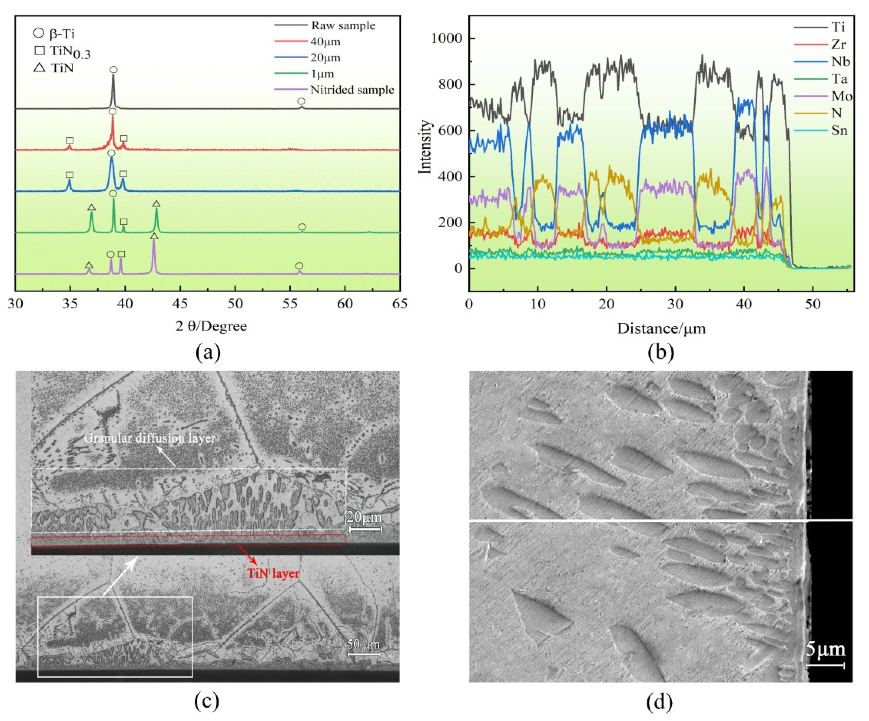
Figure 1a displays the XRD patterns from the raw samples and the nitrided sample with the removal of the nitride layer to different extents. The TLM alloy mainly consists of β-Ti phases before nitriding. After induced nitriding, TiN and TiN0.3 formed on the surface, which is similar with the results reported in the literature [20,26]. As shown in Figure 1a, compared with the nitrided sample, the diffraction pattern of the TiN phase has no significant change after the removal of the 1-μm-thick nitride layer, and the diffraction peak of the TiN phase disappears after removing the 20-μm-thick nitride layer. The results show that the nitride layer formed via the induction nitriding of the TLM alloy comprises TiN and TiN0.3 phases on the surface and TiN0.3 and β-Ti phases on the subsurface. At the beginning of the nitriding process, the TLM alloy comprises a single β-Ti phase, and the nitrogen is primarily enriched on the surface of the substrate. On prolonging the nitriding time, the transition from β phase to α phase occurs preferentially at the grain boundaries, and a finely layered secondary α phase is formed [27]. N is a stable element in the α phase, which diffuses from β phase to secondary α phase during phase transition and is enriched at phase interfaces. Therefore, the diffusion of N varies from bulk diffusion to phase interface diffusion [28], which is beneficial to increase the thickness of the nitride layer. Subsequently, the surface with a high N concentration forms the TiN phase, and the subsurface with a low N concentration forms the TiN0.3 phase.
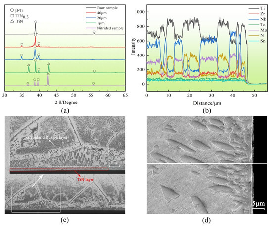
Figure 1.
Microstructure and elemental distribution of nitride layer for (a) XRD pattern of the different depths from the surface of nitrided sample (b) section elemental distribution (c) section metallography and (d) section morphology.
Figure 1c shows the cross-sectional metallographic structure of the nitrided TLM alloy etched using a Kroll etching solution under an OM. As shown in Figure 1c, a gradient nitride layer with a thickness of ~30 μm was obtained on the surface of the TLM alloy after induction nitriding. The nitride layer comprises a thin and dense TiN layer on the surface (shown by the red arrow in Figure 1c) and a granular diffusion layer on the subsurface (shown by the white arrow in Figure 1c). Moreover, to establish the distribution of elements in this sample region, the line scanning profiles are shown in Figure 1b,d. The contents of Ti and N were the highest in the nitride layer zone, whereas the contents of Zr, Nb and Mo were higher in the non-nitride layer zone.
3.2. Microhardness
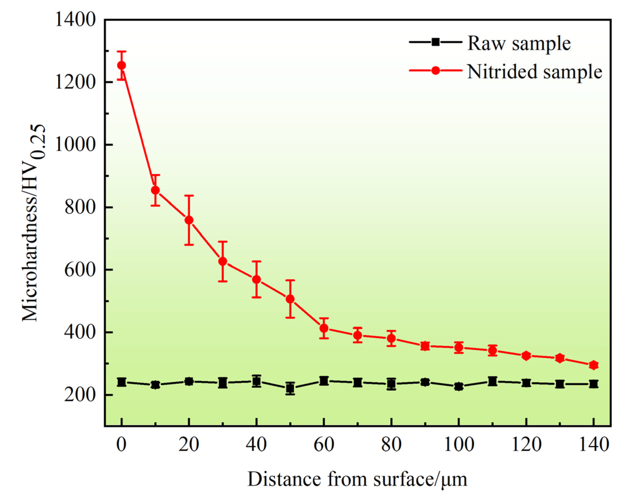
Figure 2 shows the hardness of the TLM alloy cross-section after the induction nitriding treatment. Notably, the nitride layer on the surface exhibits a very high hardness (~1253 HV), while the hardness of the nitride layer decreases with the increase in depth, and finally reaches the hardness of the substrate (~230 HV). The key reason for this considerable increase in surface microhardness is the formation of nitrides and solution strengthening of nitrogen. The formation of the TiN0.3 and TiN phases developed the hardness of the TLM alloy. TiN are hard, brittle phases [19], and thus, the formation of nitrides on the surface increases the surface hardness. The content of nitrides decreases with increasing distance from the surface, consequently, microhardness decreased with increasing distance from the surface. In addition, the error of the hardness value in the subsurface became more notable, which can be attributed to the grainy diffusion zone on the subsurface that is randomly distributed in the soft β-Ti substrate.
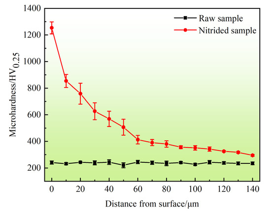
Figure 2.
Cross section hardness distribution of the raw and nitrided samples.
3.3. Electrochemical Tests
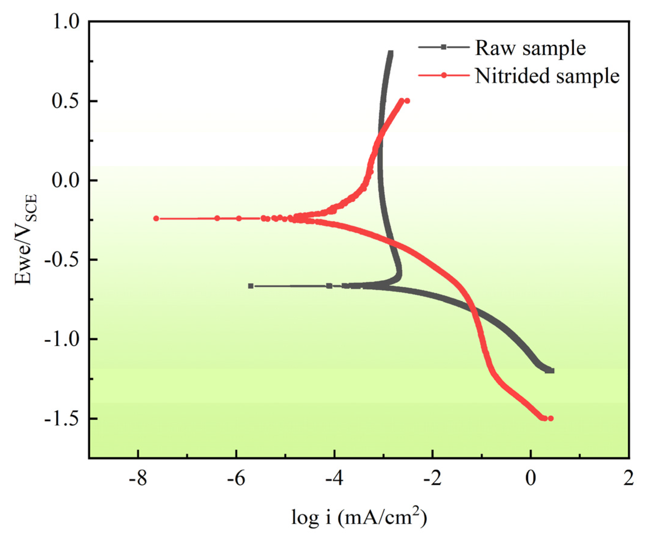
Figure 3 shows the potentiodynamic polarisation curves of the raw and the nitrided samples in SBF. The electrochemical corrosion parameters obtained by Tafel fitting are listed in Table 2. As indicated in Table 2, After Tafel fitting, we get electrochemical parameters such as corrosion current density (icorr), corrosion potential (Ecorr), anodic slope (βa) and cathodic slope (βc) are obtained after Tafel fitting. The corrosion potential of the sample after nitriding increased from −241.00 mV to −665.77 mV and the corrosion current density decreases by two orders of magnitude, which demonstrates that the corrosion resistance of TLM alloy is increased significantly after induction nitriding [29]. As shown in Figure 3, the shapes of the polarisation curves of the two samples are significantly different; indicating that the reaction mechanism is altered by the nitriding process. In the case of the raw sample, the corrosion process involves the spontaneous formation of TiO or Ti2O3, anodic transformation to TiO2, and the corresponding oxide growth [30]. However, the nitrided sample passivation region corresponds to the transformation of the TiN layer into a titanium oxy-nitride passive film, which occurs via oxidation [31]. In summary, the passivation performance of the raw sample in SBF is better than that of the nitrided sample.
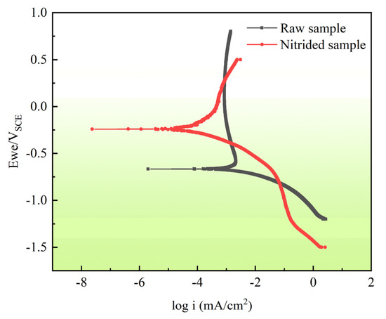
Figure 3.
Polarization curves of TLM alloy in SBF solution before and after induction nitriding.

Table 2.
Electrochemical parameters calculated according to the polarization curves in Figure 3.
3.4. Friction Response and Electrochemical Evolution with Time
3.4.1. OCP and COF Evolution during Sliding
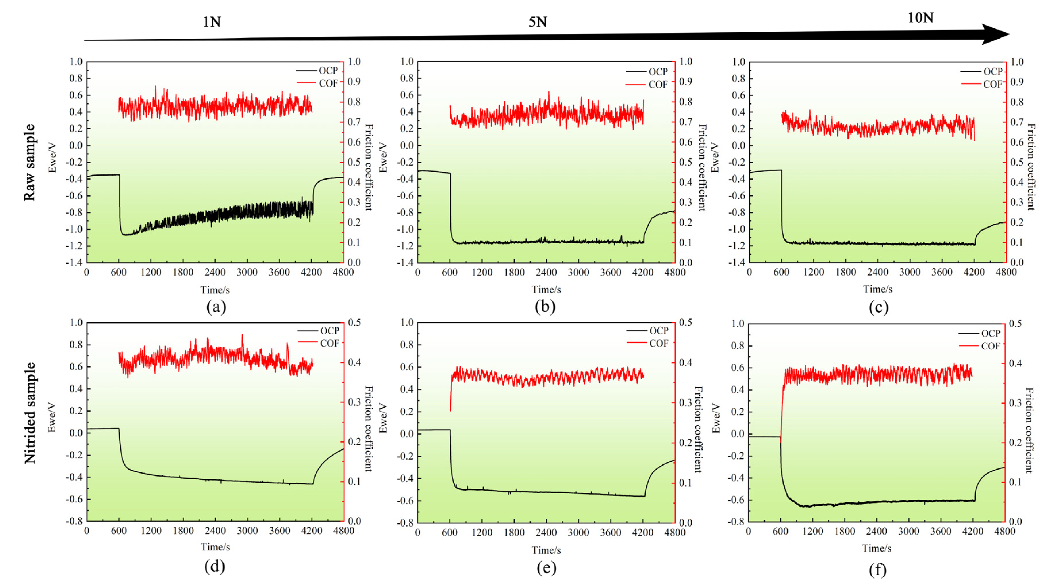
Figure 4 shows the COF and OCP of the raw and nitrided samples while standing and sliding in the SBF solution at 37 °C. At the start of the tribocorrosion testing, the OCP instantaneously transitioned to negative values because passivation film of the sample surface was damaged [32]. After the wear tribocorrosion testing, the OCP slowly increased (Figure 4), which means that the passivation film in the wear area gradually recovered while the sample was immersed in SBF [7]. However, compared with the raw samples, the decrease in the potential of the nitrided samples was smaller under the three loading conditions (Figure 4d–f), which can be attributed to the high corrosion resistance and hardness of the nitride layer. As the loading increases, the OCP of the raw and nitrided samples decreases more to an increasing extent during the tribocorrosion tests, showing that the rate of corrosion of the titanium alloy gradually increases; This is because wear accelerates the corrosion rate of the titanium alloy. Conversely, the OCP of the nitrided sample decreases from 0.42 at 1 N to 0.6 at 10 N (Figure 4d–f), indicating that the load has a greater influence on the OCP of the nitrided sample. Wear damages the passivation film and nitride layer on the surface of the sample, exposing the untreated matrix and reducing the corrosion resistance of the sample. Reciprocating wear also induces plastic deformation in the area subject to wear, increases the density of point defects and dislocations, these factors lead to higher corrosion rates [33]. During sliding, the raw sample showed considerable fluctuations in potential; these fluctuations were particularly apparent under the load of 1 N (Figure 4a). These fluctuations are caused by the dynamic depassivation and re-passivation of the substrate surface during wear [32]. The COF of the nitrided sample was considerably lower than that of the raw sample under three loads. With increasing loading magnitude, the COF of the raw sample decreases from 0.78 to ~0.68, whereas that of the nitrided sample decreases from 0.42 to ~0.37. The COF decreased after nitriding are attribute to the formation of a nitride layer with a high hardness on the nitrided sample surface. The formation of TiN0.3 and TiN hard phases develops the hardness and tribological properties of the TLM alloy. Moreover, these phases are considered as lubricant phases in which the COF is reduced. However, the hardness of the raw sample is low, the adhesive wear that occurred in the wear process yielded a high COF. These results indicate that induced nitriding treatment can effectively improve the tribocorrosion resistance of the TLM alloys.
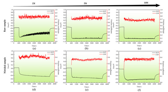
Figure 4.
Time evolution of the coefficient of friction (COF) and the potential (OCP) during the tribocorrosion test of the raw sample and the nitrided samples in SBF solution for (a–c) Raw samples; (d–f) Nitrided samples.
3.4.2. Current Evolution during Sliding
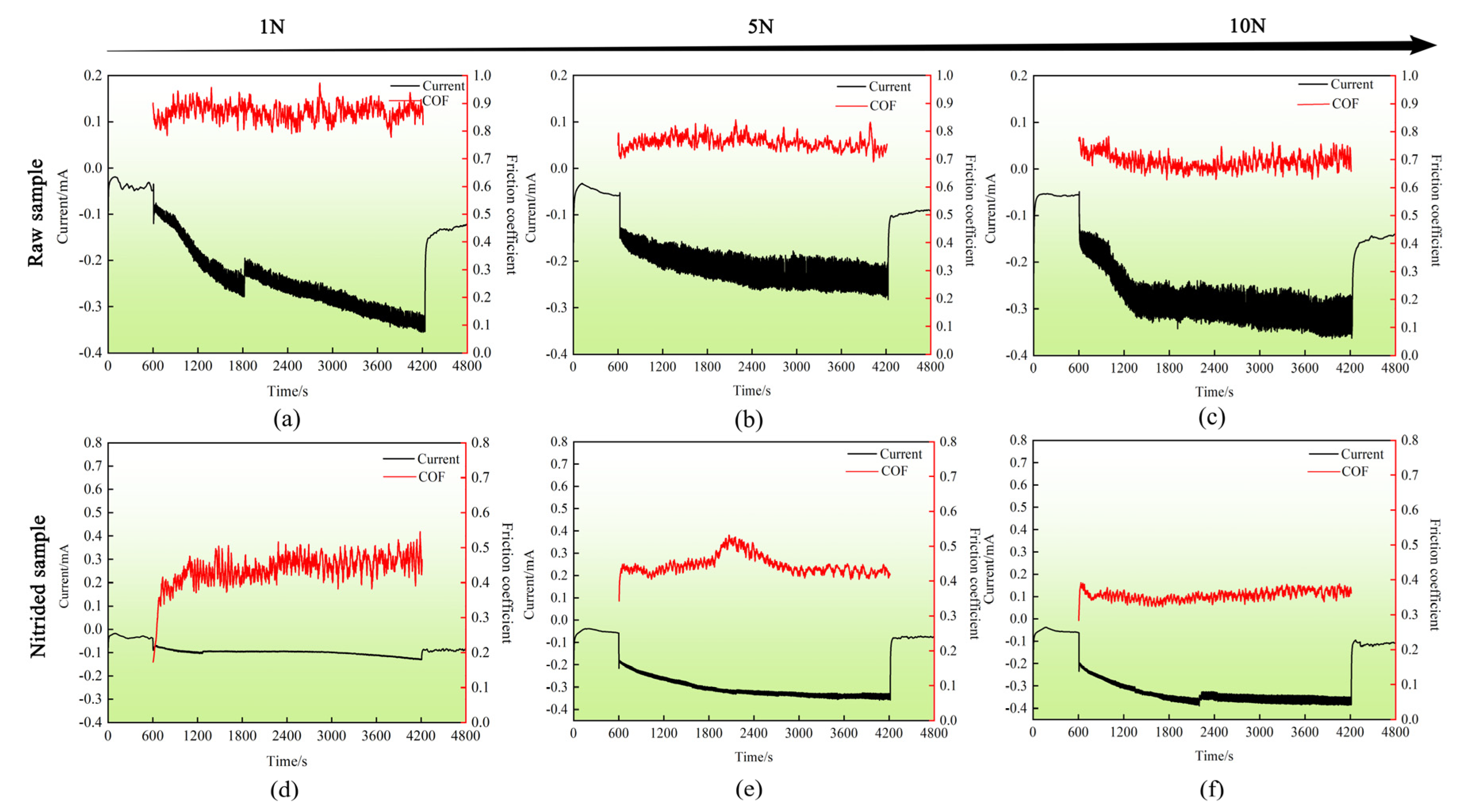
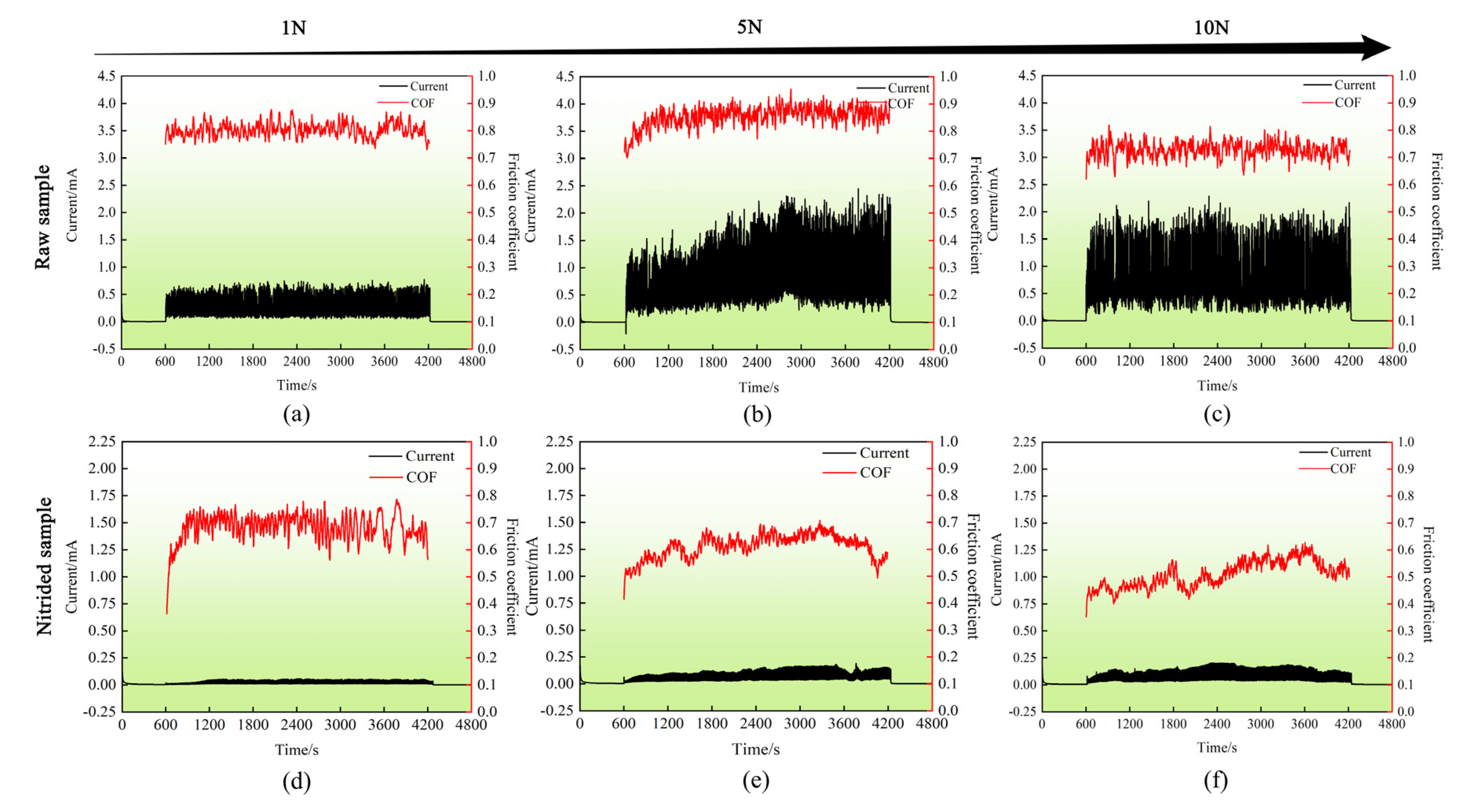
Figure 5 and Figure 6 show the evolution of the COF and the measured current with time during the tribocorrosion test of the raw and nitrided samples subject to applied potentials of −1.2 and 1 V, respectively.
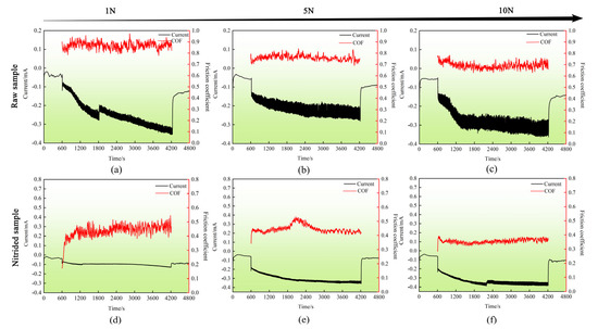
Figure 5.
Evolution of the coefficient of friction (COF) and the current during the tribocorrosion test of the cathodic applied potential (E = −1.2 V) for (a–c) Raw samples; (d–f) Nitrided samples.
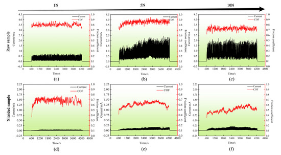
Figure 6.
Evolution of the coefficient of friction (COF) and the current during the tribocorrosion test of the anodic cathodic applied potential (E = 1.0 V) for (a–c) Raw samples; (d–f) Nitrided samples.
In the case of the cathodic applied potential (E = −1.2 V), the negative current measured corresponds to redox (dissolved oxygen and water) [34,35]. As shown in Figure 5, the measured current acquired increasingly negative values during sliding, indicating successful cathodic protection [36]. During the tribocorrosion process, the current fluctuated in both the raw and nitrided samples, and the amplitude of the fluctuation increases with the increase in load. The cause of these phenomena is hypothesised to be a dynamic balance between depassivation and re-passivation of the sample surface in the affected region. The COF of the nitrided samples were lower than those of the raw samples under different loading conditions. With increasing loading magnitude, the COF of the raw and nitrided samples decreases gradually. This may be because as the load increases, more debris is generated and some of which acts as a lubrican during friction process, resulting in the decrease in COF.
Under an anodic applied potential (E = 1.0 V), as shown in Figure 6, an abrupt increase in the current was observed at the initiation of the tribocorrosion testing. The current increases rapidly are attributed to the damage of the passivation film on the sample surface and subsequent re-passivation. After the tribocorrosion ceases, the passivation film again forms on the sample surface and the current returns to its initial state. These observations are consistent with the findings in the existing literature [37]. In addition, the current observed in the raw and nitrided samples can increase as the load increases during sliding. The reason for this phenomenon may be that the depassivation area increases with the loading magnitude [38]. Compared with OCP condition, COF of the raw and nitrided samples increased slightly under anodic potential. This may be due to the destruction of the wear mark being accelerated under an anodic potential and the effect of corrosion yielding a deeper and wider wear region. The anodic currents of the raw and nitrided samples are shown in Table 3 for the different loading conditions, and these data are used for the calculation in Section 3.6. Under the same conditions, the corrosion current ic and wear current iw of the raw sample are both one order of magnitude higher than those of the nitrided sample; the lower current and smaller fluctuation range indicate that the nitride sample has better corrosion and wear resistance. As the load increases, the wear currents observed in the raw and nitrided samples gradually increase. The wear current iw and the COF curves of the nitrided sample are lower than those of the raw sample, indicating that the nitride layer has good antifriction effect.

Table 3.
Anodic currents of the raw and nitrided samples under different loads.
3.5. Wear Morphology and Profile
3.5.1. OCP Condition
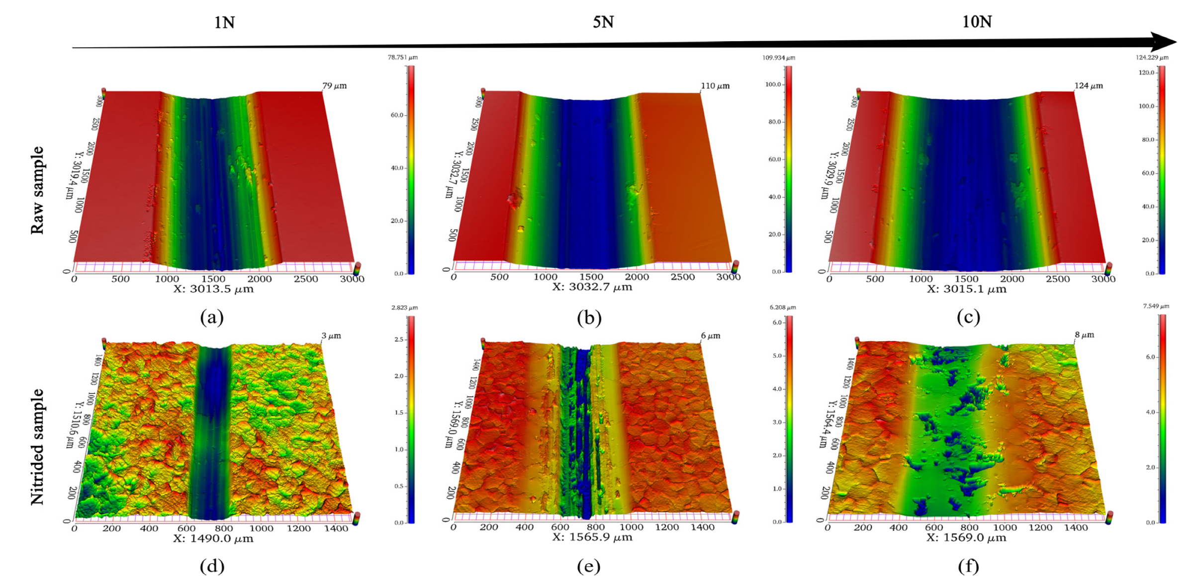
Figure 7 shows the 3D wear morphology of the raw and nitrided samples after the tribocorrosion test at OCP. As shown in Figure 7a–c, grooves along the sliding direction can be observed in the raw sample, the depth and width of the abrasion marks gradually increase with increasing loading. The nitrided sample showed a smooth wear surface (Figure 7d–f). It can be seen that the width and depth of the abrasion marks in the nitrided sample are considerably smaller than those observed in the raw sample. This observation can be attributed to three reasons. (1) The nitrided sample resulted the higher fatigue strength due to its higher hardness, which can effectively reduce the material loss caused by pure mechanical wear [39,40], (2) the excellent corrosion resistance of the nitride layer can considerably reduce the corrosion effect, and (3) a granular diffusion layer cooperates more effectively with the nitride layer of the surface to carry the contact stress and avoid stress concentrations at the interface and in the nitride layer [41,42]. The tribocorrosion resistance of titanium alloy is improved by the combined action of these factors, reducing the extent of the wear.
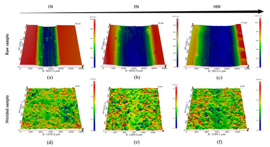
Figure 7.
3D wear morphology after the tribocorrosion test of the (a–c) raw sample and the (d–f) nitrided sample at OCP in SBF solution.
3.5.2. Applied Potentials Conditions
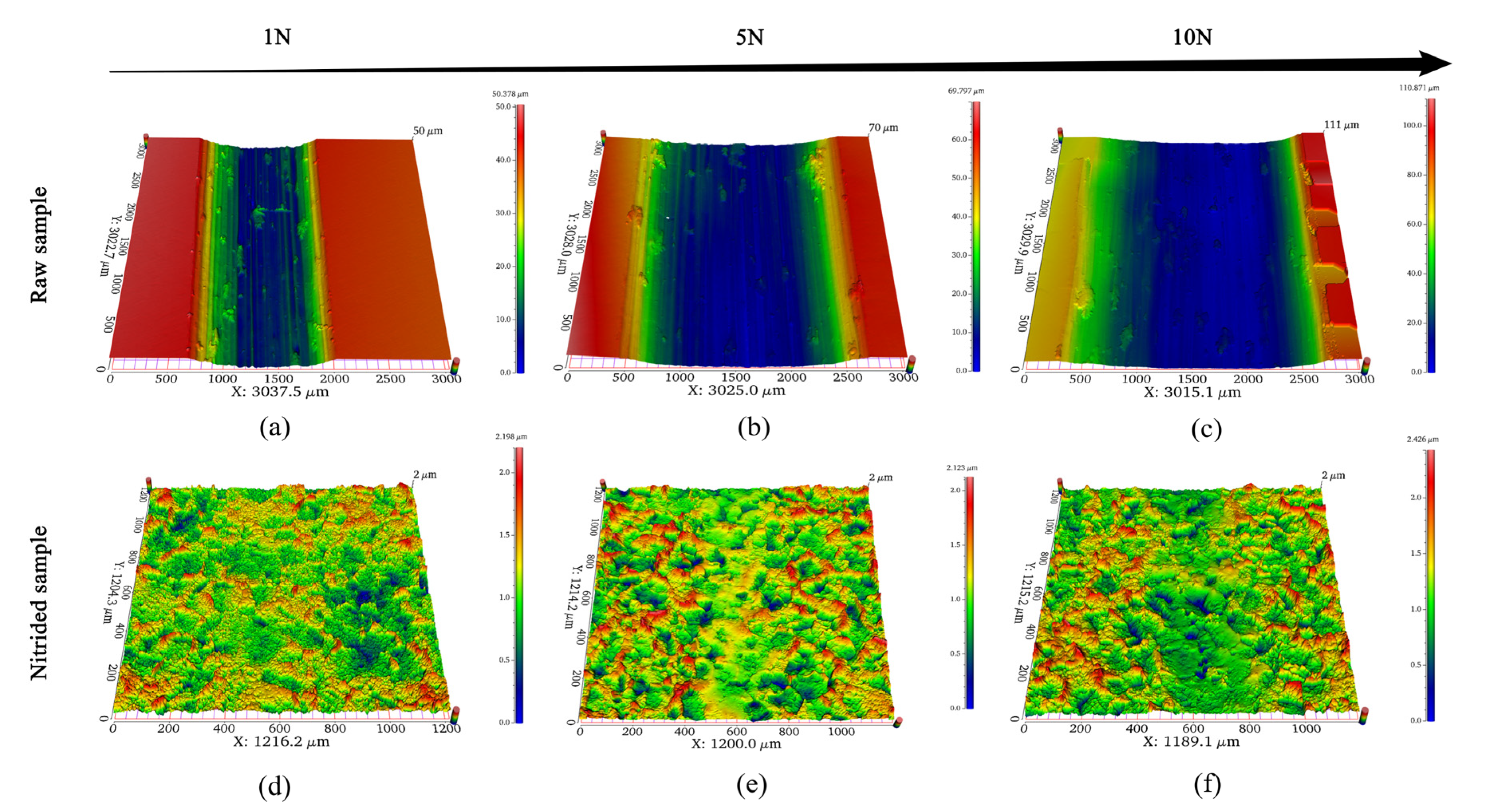
Figure 8 shows the 3D morphology of the raw and nitrided samples after a tribocorrosion test at cathodic potential (E = −1.2 V). It can be seen in Figure 8 that no pits or any other forms of corrosion are present on the sample surface after the tribocorrosion test under a cathodic potential. As there is only a wear effect at the cathodic potential, it can be hypothesised that wear has a more considerable impact on material loss than corrosion [36]. Under three different loads conditions, the abrasion marks in the raw sample were visible, and the width and depth of the abrasion marks increased considerably with increasing load. However, the abrasion marks in the nitrided sample under a loads of 1 and 5 N loads were difficult to identify (Figure 8d,e), and only slight abrasion marks were found on the surface of the nitrided sample subjected to a loading of 10 N. Compared with the wear morphology observed under an OCP, the wear morphologies of the raw and nitrided samples are narrower and shallower under a cathodic potential and the same load, indicating that the applied cathodic potential can effectively reduce the material loss of titanium alloy.
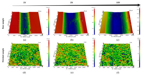
Figure 8.
3D wear morphology after the tribocorrosion test of the (a–c) raw sample and the (d–f) nitrided sample at cathodic applied potential (E = −1.2 V) in SBF solution.
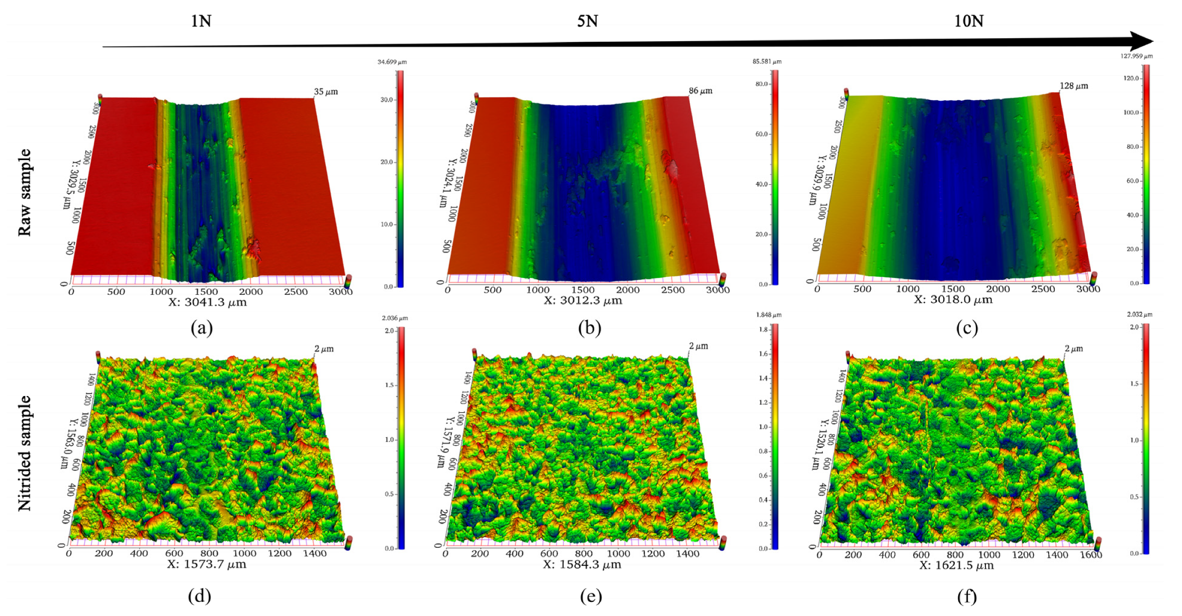
Figure 9 shows the 3D morphology of the raw and nitrided samples after a tribocorrosion test subjected to an anodic potential (E = +1.0 V). Compared with the samples subjected to OCP or cathodic potential, the width and depth of abrasion marks on the nitrided sample subjected to an anodic potential are significantly increased. This is because the corrosion rate is accelerated at the anodic potential, and the promoting effect of corrosion on wear is also enhanced. With the increase in loading, the width of the abrasion marks in the raw and nitrided samples also increases. In addition, Figure 9e,f shows that there are many exfoliation pits in the abrasion marks. This may be because the anodic potential accelerates the corrosion of the nitride layer during the tribocorrosion test, the top nitride layer is more likely to be damaged and spalling can occur under large loads.
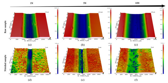
Figure 9.
3D wear morphology after the tribocorrosion test of the (a–c) raw sample and the (d–f) nitrided sample at anodic applied potential (E = 1.0 V) in SBF solution.
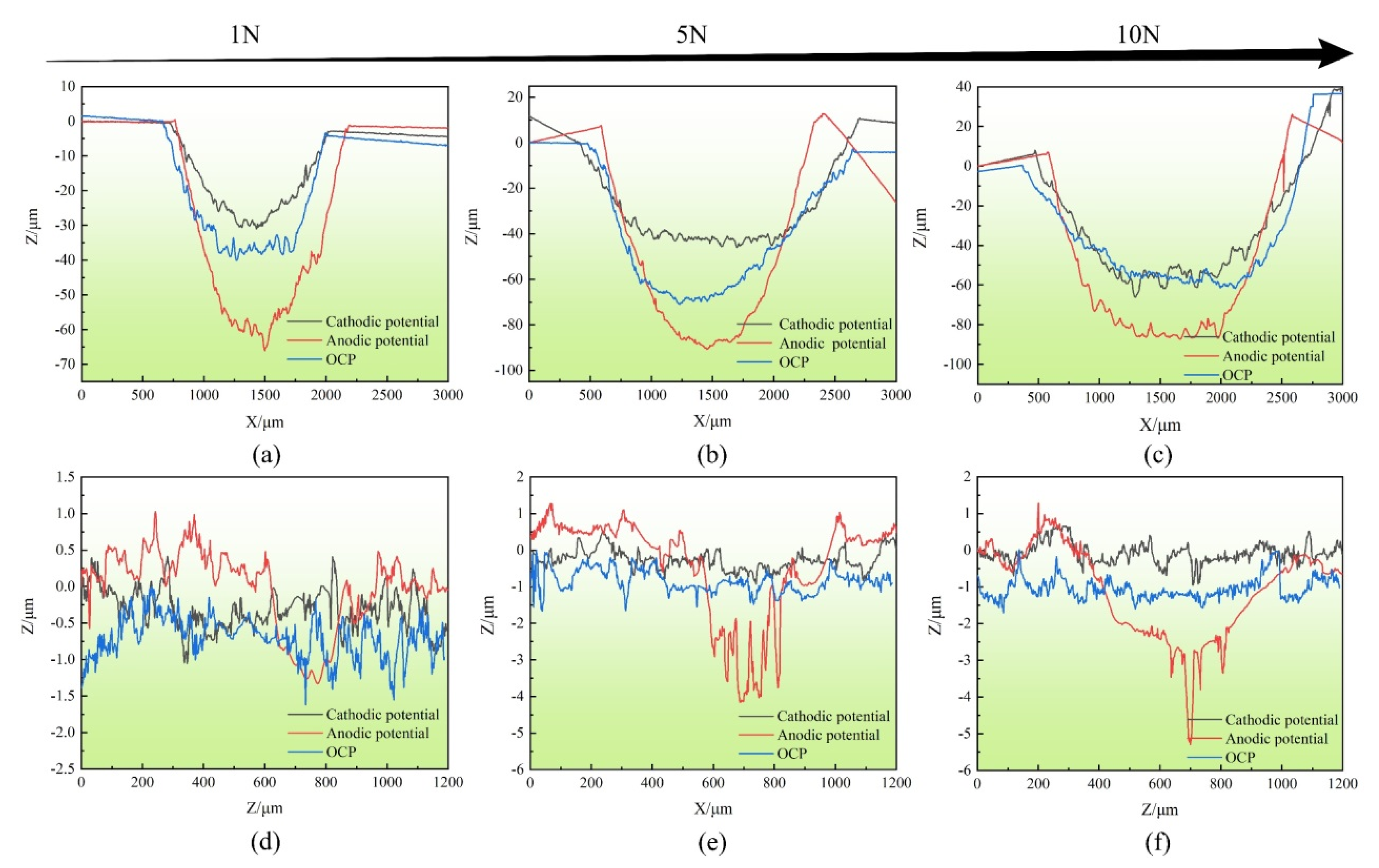
Figure 10 shows the wear profiles of the raw and nitrided samples after the tribocorrosion test, with the sample subject to cathodic protection, OCP and anodic corrosion. It can be seen that the application of a cathodic potential protects the raw and nitrided samples and reduces the material loss observed in the sample. Applying anodic potential considerably increases material loss because this increases the wear and corrosion synergistic effects. Consequently, the width and depth of the wear profile of the nitrided sample considerably increases under the anodic potential (E = +1.0 V).
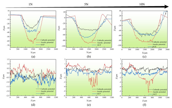
Figure 10.
Wear profile after the tribocorrosion test of the (a–c) raw sample and the (d–f) nitrided sample under different conditions.
3.6. Synergistic Effects of Wear and Corrosion
The biological tribocorrosion damage induced in titanium alloys is cumulative, resulting from the corrosion, mechanical wear, and the synergistic effect of these two factors [43]. Generally, the below expression is used to quantify material loss in a tribocorrosion test [44].
where WT represents the total material loss, which is the material loss observed on the sample after the tribocorrosion test at the anodic potential; WA is the mechanical material loss, which is the material loss of the sample after the tribocorrosion test at a cathodic potential of −1.2 V, as suggested in the ASTM G119 standard; and WS represents the material loss caused by the synergistic effect of corrosion and wear. WC is the material loss induced by pure corrosion, which is the material loss that can be calculated following Faraday’s law and applying the following expression [44].
where M is the molecular weight of titanium, I is the current (ic) during the sliding process in the tribocorrosion test at an anodic potential of +1.0 V, t is the corrosion time (3600 s), n is the oxidation state of the sample and F is the Faraday constant (96,500 C/mol).
The term Ws can be decomposed into two parts. SA, which represents the increase in mechanical wear due to corrosion, and SC, which represents the increase in corrosion due to mechanical wear. These terms are combined to calculate WS, as shown below [44].
Using Faraday’s law, the increment in the mechanical wear due to corrosion can be obtained as [44].
where M represents the molecular weight of titanium; n and F are the oxidation state of the sample and Faraday constant, respectively; ic is the corrosion current density and iw is the wear current density measured at an anodic potential of +1.0 V.
Considering Equations (1) and (3), one can obtain,
Therefore, the change in the mechanical wear due to the corrosion can be calculated as.
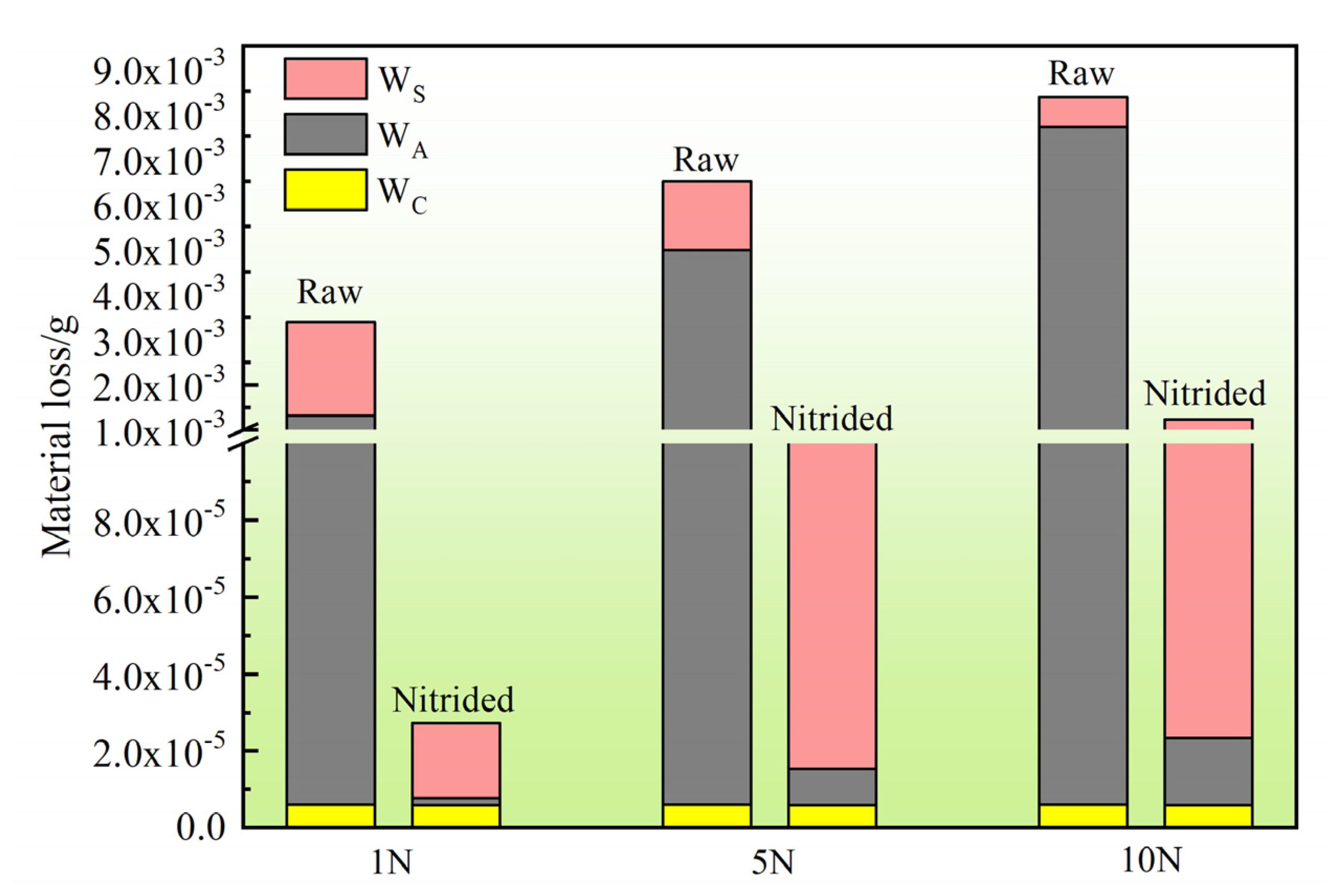
Figure 11 and Table 4 show the material loss observed in the raw sample and nitrided samples obtained by using the above expression under different loads at the anodic potential of +1.0 V. As shown in Table 4, the mechanical material loss (WA) of the nitride sample was only 0.23% of the substrate under a 10 N load, and the total material loss (WT) was 15% of the substrate. It can be seen that the influence of pure corrosion (WC) on the total material loss can be neglected. In the case of the raw sample, the total material loss (WT) is dominated by the mechanical material loss (WA); the synergistic effect of wear and corrosion (WS) also increases the material loss in the raw sample. However, the proportion (WS/WT) of material loss caused by the synergistic effect of corrosion and wear (WS) gradually decreases with increasing load. It is hypothesised that this is attributed to the substrate of the TLM alloy being softer. During the tribocorrosion test, the soft matrix will undergo plastic deformation under the repeated action of the Al2O3 ball, which causes the work-hardening effect. As the load increases, the work-hardening effect becomes more significant, which effectively reduces the wear effect. The nitrided sample exhibits trends that are the opposite to those observed in the case of the raw sample; the proportion (WS/WT) of material loss caused by the synergistic effect of corrosion and wear (WS) increased gradually with increasing load. The mechanical wear due to corrosion (SA) increased gradually with increasing load. The externally applied anodic potential accelerates the corrosion of the nitride layer [45] and then increases the wear extent; corrosion and wear mutually promote a synergistic effect to accelerate the loss of materials. With increasing loading magnitude, the nitride layer will be damaged to a larger extent. In this case, the exfoliation pit observed on the nitrided sample (Figure 9f) induced during the tribocorrosion test can provide diffusion channels for the corrosive medium, forming a galvanic corrosion cell between the nitride layer and the substrate [46,47] which increases corrosion due to mechanical wear (SC). The top nitride layer in the tribocorrosion test produces more wear debris under large loads, causing third-bodies wear that may afford increases in the extent of wear the sample undergoes. Under the loading conditions of 1, 5 and 10 N, the WS/WT ratio of the raw sample was 61.06, 23.35 and 7.93%, respectively, and that of the nitrided sample was 71.32, 97.44 and 98.37%, respectively.
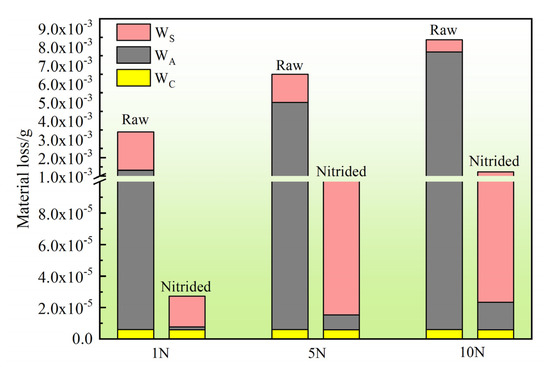
Figure 11.
Material loss of the raw and nitrided samples subjected to tribocorrosion at anodic potential (E = 1.0 V) under different loads.

Table 4.
Material loss components of tribocorrosion of the raw and nitride samples at anodic potential (E = 1.0 V) under different loads.
3.7. Tribocorrosion Mechanism
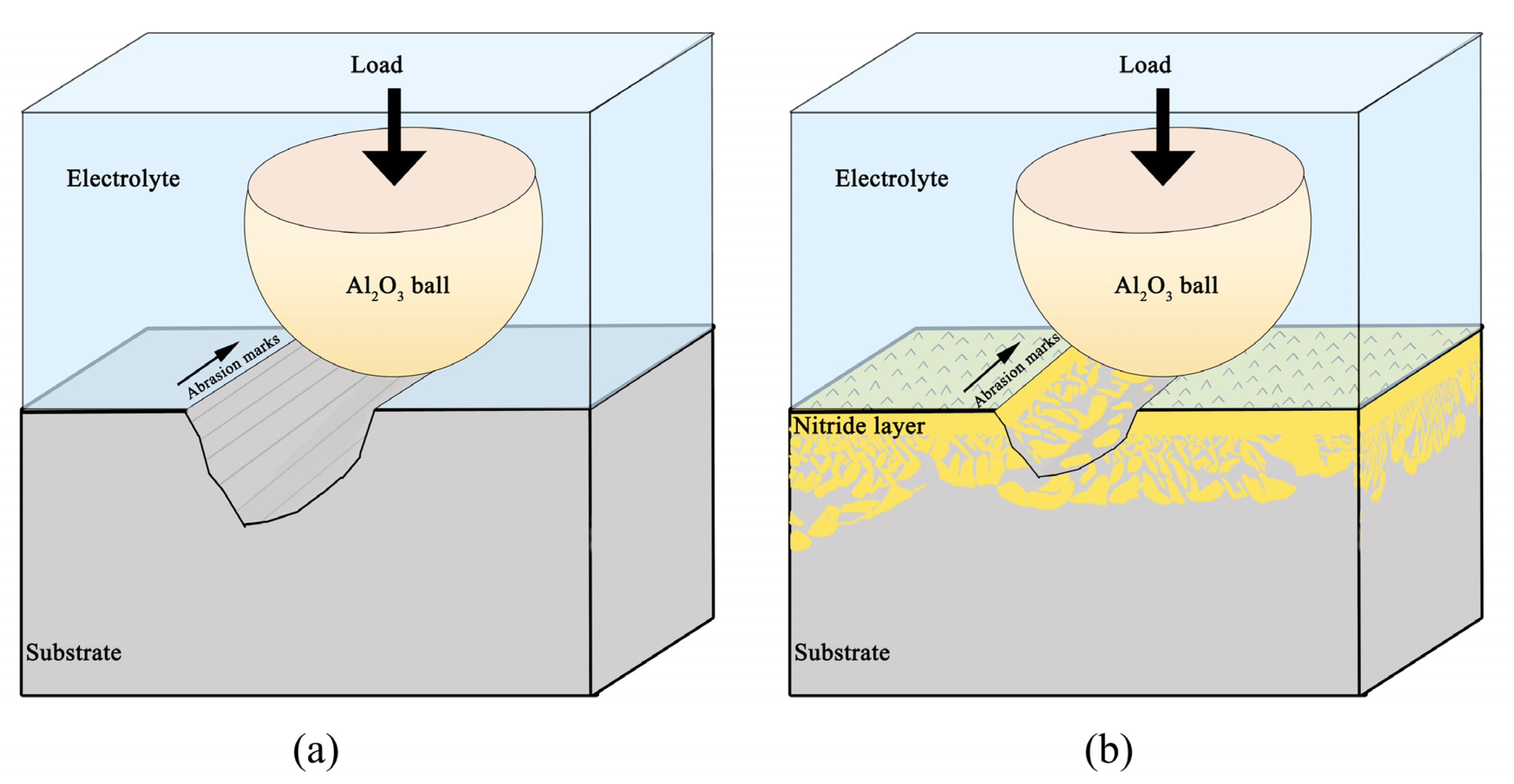
The suggested tribocorrosion mechanisms of the TLM titanium alloy before and after induction nitriding are shown in Figure 12. The parallel grooves in the abrasion marks on the raw and nitrided samples indicate the generation of abrasive wear, which can be explained by the ploughing action of debris on the alloy surface. It has been reported that different β-type titanium alloys have similar dominant abrasive and adhesive mechanisms under different testing conditions [48,49]. The raw sample showed a higher extent of material loss and a higher COF, which are associated with the formation of adhesive wear, as evidenced by the wear debris observed in the raw sample abrasion marks (Figure 8a–c). The relatively smooth wear surface observed on the nitrided sample indicates that the hardness of the material plays a vital role in the wear process. Considering that the hardness of the Al2O3 ball (~2300 HV) and TLM alloys (~230 HV) are significantly different, it can be inferred that ploughing friction is the primary factor responsible for observed material loss. The wear mechanisms in the case of the raw samples with relatively low hardness are mainly adhesive wear and abrasive wear. The wear mechanism in the case of the nitrided sample is abrasive wear, which is due to the bearing effect of the hard TiN phase on the surface [50] and the support effect of the granular diffusion layer with gradient distribution in the subsurface. After nitriding, uniform coarse grains of about 100 μm were formed on the surface while raised titanium nitride was formed in the grain boundary. This hard phase produced a relatively ordered microscopic texture along with the grain boundary, which can effectively reduce the contact area between the grinding ball and the TLM alloy, the shear force, and then the COF and wear amount. During tribocorrosion testing, a granular diffusion layer cooperates more effectively with the nitride layer of the surface to carry the contact stress, avoiding stress concentrations in the nitride layer and at the interface [41,42]. The improved tribocorrosion resistance of TLM alloy is mainly attributed to the compact TiN layer with high hardness and corrosion resistance on the surface and the coordinated deformation of the granular diffusion layer on the subsurface. Moreover, the nitride layer has excellent corrosion resistance, which considerably increases the tribocorrosion resistance of the nitrided sample. However, in the system with the interaction of corrosion and wear, the applied anodic potential and the formation of the galvanic corrosion cell accelerate the corrosion of the nitride layer. Due to the damage of the nitride layer, the potential decreased rapidly, and the potential difference between the grain areas thus went up, resulting in corrosion intensifies. Under the dual action of shear stress and corrosion, the grain boundary bulged, and the damage was accelerated, which induced the disappearance of the microscopic texture, the rapid increase in the friction area, and the remarkable promotion of the COF and wear volume. This makes the sample more vulnerable to damage under large loads. The formation of hard-wear debris can act as the third-body particle and eventually accelerate material loss [51]. The increase in mechanical wear due to corrosion makes the synergistic effect of wear and corrosion in the nitrided sample increase with increasing load, showing a trend contrary to that observed in the case of the raw sample.
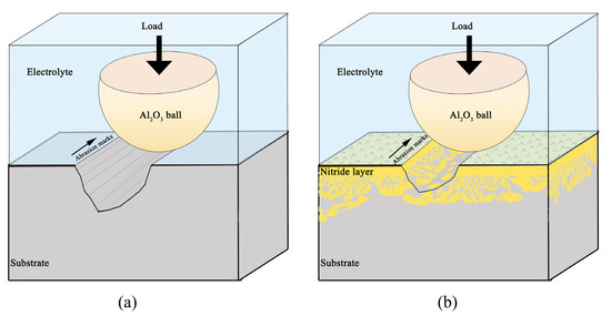
Figure 12.
Schematic illustrations of tribocorrosion mechanisms for (a) Raw sample (b) Nitrided sample.
4. Conclusions
The tribocorrosion behaviour of nitride layer prepared on TLM alloy under SBF was studied. After induction nitriding, surface hardness increased from approximately 230 to 1253 HV and the surface of the TLM alloy formed a nitride layer of approximately 30-μm -thick. The nitride layer shows a gradient structure, which comprises a TiN layer on the surface and a granular diffusion layer distributed on the subsurface. Moreover, The TLM alloy has excellent tribocorrosion resistance after induction nitriding, the mechanical material loss (WA) of the nitride sample was only 0.23% of the substrate under a 10 N load, and the total material loss (WT) was 15% of the substrate. As the load increases, the material loss increases, and the applied anodic potential accelerates the material loss. The total material loss observed in the raw sample during the tribocorrosion test was primarily due to the mechanical wear; and the synergistic effect of corrosion and wear is the main factor causing material loss in the case of the nitrided sample. In conclusion, the nitride layer is a kind of coating with high hardness and corrosion resistance, which can enhance the tribocorrosion behaviour under physiological environment, so as to extend the biomedical application life of titanium alloy. In further research work, we hope to conduct animal experiments to make up for the current deficiency of in vivo experiments.
Author Contributions
Formal analysis, Y.D. and X.J.; Investigation, Y.D., X.J. and K.L.; Methodology, Y.D., X.J. and J.L.; Conceptualization, K.L. and M.O.; Writing—original draft, Y.D.; Writing—review & editing, Y.D., Q.X. and J.L.; Supervision, M.O. and F.Y.; Funding acquisition, Q.X., F.Y. and J.L. All authors have read and agreed to the published version of the manuscript.
Funding
This research was funded by the Guizhou Provincial Science and Technology Foundation Grant No. ZK [2022]319 and No. [2020]1Z041), the National Natural Science Foundation of China (No. 51574096) and the Education Department of Guizhou Province supports the scientific research platform project of provincial universities (No. [2022]012).
Institutional Review Board Statement
Not applicable.
Informed Consent Statement
Not applicable.
Data Availability Statement
Not applicable.
Conflicts of Interest
The authors declare no conflict of interest.
References
- Gwam, C.; Mistry, J.B.; Mohamed, N.; Thomas, M.; Bigart, K.C.; Mont, M.A.; Delanois, R.E. Current epidemiology of revision total hip arthroplasty in the United States: National inpatient sample 2009 to 2013. Arthroplasty 2017, 32, 2088–2092. [Google Scholar] [CrossRef]
- Xie, K.Y.; Wang, Y.B.; Zhao, Y.; Chang, L.; Wang, G.; Chen, Z.; Cao, Y.; Liao, X.; Lavernia, E.J.; Valiev, R.Z.; et al. Nanocrystalline β-Ti alloy with high hardness, low Young’s modulus and excellent in vitro biocompatibility for biomedical applications. Mater. Sci. Eng. C 2013, 33, 3530–3536. [Google Scholar] [CrossRef]
- Heilshorn, S.C.; Goodman, S.B.; Raphel, J.; Holodniy, M. Multifunctional coatings to simultaneously promote osseointegration and prevent infection of orthopaedic implants. Biomaterials 2016, 84, 301–314. [Google Scholar] [CrossRef]
- Krikke, H.; van der Laan, E. International journal of advanced manufacturing technology introduction to the special issue. Int. J. Adv. Manuf. Technol. 2021, 115, 1605–1620. [Google Scholar] [CrossRef]
- Yetim, T. Corrosion behavior of Ag-doped TiO2 coating on commercially pure titanium in simulate bod fluid solute. J. Bionic. Eng. 2016, 13, 397–405. [Google Scholar] [CrossRef]
- Urena, J.; Tsipas, S.; Pinto, A.M.; Toptan, F.; Gordo, E.; Jimenez-Morales, A.J. Corrosion and tribocorrosion behavior of β-type Ti-Nb and Ti-Mo surfaces designed by diffusion treatments for biomedical applications. Corros. Sci. 2018, 140, 51–60. [Google Scholar] [CrossRef]
- Geetha, M.; Singh, A.K.; Asokamani, R.; Gogia, A.K. Ti based biomaterials, the ultimate choice for orthopaedic implants—A review. Prog. Mater. Sci. 2009, 54, 397–425. [Google Scholar] [CrossRef]
- Jamari, J.; Ammarullah, M.I.; Santoso, G.; Sugiharto, S.; Supriyono, T.; van der Heide, E. In silico contact pressure of metal-on-metal total hip implant with different materials subjected to gait loading. Metals 2022, 12, 1241. [Google Scholar] [CrossRef]
- Zhang, L.C.; Chen, L.Y.; Wang, L.Q. Surface modification of titanium and titanium alloys: Technologies, developments, and future interests. Adv. Eng. Mater. 2020, 5, 1901258. [Google Scholar] [CrossRef]
- Pawłowski, Ł.; Rościszewska, M.; Majkowska-Marzec, B.; Jażdżewska, M.; Bartmański, M.; Zieliński, A.; Tybuszewska, N.; Samsel, P. Influence of surface modification of titanium and its alloys for medical implants on their corrosion behavior. Materials 2022, 15, 7556. [Google Scholar] [CrossRef]
- Ongtrakulkij, G.; Kajornchaiyakul, J.; Kondoh, K.; Khantachawana, A. Investigation of microstructure, residual stress, and hardness of Ti-6Al-4V after plasma nitriding process with different times and temperatures. Coatings 2022, 12, 1932. [Google Scholar] [CrossRef]
- Kikuchi, S.; Yoshida, S.; Ueno, A. Improvement of fatigue properties of Ti-6Al-4V alloy under four-point bending by low temperature nitriding. Int. J. Fatigue. 2019, 120, 134–140. [Google Scholar] [CrossRef]
- Chouirfa, H.; Bouloussa, H.; Migonney, V.; Falentin-Daudré, C. Review of titanium surface modification techniques and coatings for antibacterial applications. Acta Biomater. 2019, 83, 37–54. [Google Scholar] [CrossRef] [PubMed]
- Kamat, A.M.; Copley, S.M.; Segall, A.E.; Todd, J.A. Laser-sustained plasma (LSP) nitriding of titanium: A review. Coatings 2019, 9, 283. [Google Scholar] [CrossRef]
- Jambagi, S.C.; Malik, V.R. A Review on surface engineering perspective of metallic implants for orthopaedic applications. JOM 2021, 73, 4349–4364. [Google Scholar] [CrossRef]
- Chan, C.W.; Lee, S.; Smith, G.; Sarri, G.; Ng, C.H.; Sharba, A.; Man, H.C. Enhancement of wear and corrosion resistance of beta titanium alloy by laser gas alloying with nitrogen. Appl. Surf. Sci. 2016, 367, 80–90. [Google Scholar] [CrossRef]
- Sathish, S.; Geetha, M.; Pandey, N.D.; Richard, C.; Asokamani, R. Studies on the corrosion and wear behavior of the laser nitrided biomedical titanium and its alloys. Mater. Sci. Eng. C 2010, 30, 376–382. [Google Scholar] [CrossRef]
- Fernandes, A.C.; Vaz, F.; Ariza, E.; Rocha, L.A.; Ribeiro, A.R.L.; Vieira, A.C.; Rivière, J.P.; Pichon, L. Tribocorrosion behaviour of plasma nitrided and plasma nitride + oxidised Ti6Al4V alloy. Surf. Coat. Technol. 2006, 200, 6218–6224. [Google Scholar] [CrossRef]
- Xiang, H.; Ke, F.; Tan, Y.F.; Wang, X.L.; Hua, T. Effects of process parameters on microstructure and wear resistance of TiN coatings deposited on TC11 titanium alloy by electrospark deposition. Trans. Nonferrous Met. Soc. China 2017, 27, 1767–1776. [Google Scholar] [CrossRef]
- Das, S.; Guha, S.; Ghadai, R.K.; Sharma, A. Influence of nitrogen gas over microstructural, vibrational and mechanical properties of CVD Titanium nitride (TiN) thin film coating. Ceram. Int. 2021, 47, 16809–16819. [Google Scholar] [CrossRef]
- Cheng, J.; Li, J.S.; Yu, S.; Du, Z.X.; Zhang, X.Y.; Zhang, W.; Gai, J.Y.; Wang, H.C.; Song, H.J.; Yu, Z.T. Cold rolling deformation characteristic of a biomedical beta type Ti-25Nb-3Zr-2Sn-3Mo Alloy plate and its influence on alpha precipitated phases and room temperature mechanical properties during aging treatment. Front. Bioeng. Biotechnol. 2020, 8, 598529. [Google Scholar] [CrossRef] [PubMed]
- Kent, D.; Wang, G.; Yu, Z.; Dargusch, M.S. Pseudoelastic behaviour of a β Ti–25Nb–3Zr–3Mo–2Sn alloy. Mater. Sci. Eng. A 2010, 527, 2246–2252. [Google Scholar] [CrossRef]
- Wang, Z.G.; Li, Y.; Huang, W.J.; Chen, X.L.; He, H. Micro-abrasion-corrosion behaviour of a biomedical Ti–25Nb–3Mo–3Zr–2Sn alloy in simulated physiological fluid. J. Mech. Behav. Biomed. 2016, 63, 361–374. [Google Scholar] [CrossRef] [PubMed]
- Li, K.M.; Song, K.J.; Guan, J.; Yang, F.; Liu, J. Tribocorrosion behavior of a Ti6Al4V alloy electromagnetic induction nitride layer in a fluorine-containing solution. Surf. Coat. Technol. 2020, 386, 125506. [Google Scholar] [CrossRef]
- Guan, J.; Jiang, X.T.; Xiang, Q.; Yang, F.; Liu, J. Corrosion and tribocorrosion behavior of titanium surfaces designed by electromagnetic induction nitriding for biomedical applications. Surf. Coat. Technol. 2021, 409, 126844. [Google Scholar] [CrossRef]
- Jiang, X.T.; Dai, Y.; Xiang, Q.; Liu, J.; Yang, F.; Zhang, D.X. Microstructure and wear behavior of inductive nitriding layer in Ti-25Nb-3Zr-2Sn-3Mo alloys. Surf. Coat. Technol. 2021, 427, 127835. [Google Scholar] [CrossRef]
- Jiang, X.J.; Wang, S.Z.; Feng, Z.H.; Qi, H.B.; Fu, H.; Liu, R.P. Improving vacuum gas nitriding of a Ti-based alloy via surface solid phase transformation. Vacuum 2022, 197, 110860. [Google Scholar] [CrossRef]
- Barda, H.; Rabkin, E. The role of interface diffusion in solid state dewetting of thin films: The nano-marker experiment. Acta Mater. 2019, 177, 121–130. [Google Scholar] [CrossRef]
- Lin, N.M.; Huang, X.B.; Zhang, X.Y.; Fan, A.; Lin, Q.; Tang, B. In vitro assessments on bacterial adhesion and corrosion performance of TiN coating on Ti6Al4V titanium alloy synthesized by multi-arc ion plating. Appl. Surf. Sci. 2012, 258, 7047–7051. [Google Scholar] [CrossRef]
- Wei, Y.; Pan, Z.M.; Yu, F.; Yu, W.; He, S.; Yuan, Q.; Luo, H.; Li, X. Effect of annealing temperatures on microstructural evolution and corrosion behavior of Ti-Mo titanium alloy in hydrochloric acid. Corros. Sci. 2022, 197, 110079. [Google Scholar] [CrossRef]
- Xu, Y.D.; Qi, J.H.; Nutter, J.; Sharp, J.; Nathet, S. Correlation between the formation of tribofilm and repassivation in biomedical titanium alloys during tribocorrosion. Tribol. Int. 2021, 163, 107147. [Google Scholar] [CrossRef]
- Si, Y.H.; Liu, H.Y.; Yu, H.Y.; Jiang, X.Z.; Sun, D.B. A heterogeneous TiO2/SrTiO3 coating on titanium alloy with excellent photocatalytic antibacterial, osteogenesis and tribocorrosion properties. Surf. Coat. Technol. 2022, 431, 128008. [Google Scholar] [CrossRef]
- Pohrelyuk, L.M.; Fedriko, V.M.; Tkachuk, O.V.; Proskurnyak, R.V. Corrosion resistance of Ti-6Al-4V alloy with nitride coatings in Ringer’s solution. Corros. Sci. 2013, 66, 392–398. [Google Scholar] [CrossRef]
- Milosev, I.; Kosec, T.; Strehblow, H.H. XPS and EIS study of the passive film formed on orthopaedic Ti-6Al-7Nb alloy in Hank’s physiological solution. Electrochim. Acta. 2008, 53, 3547–3558. [Google Scholar] [CrossRef]
- Milosev, I.; Zerjav, G.; Moreno, J.M.C.; Popa, M. Electrochemical properties, chemical composition and thickness of passive film formed on novel Ti-20Nb-10Zr- 5Ta alloy. Electrochim. Acta 2013, 99, 176–189. [Google Scholar] [CrossRef]
- Alkan, S.; Gok, M.S. Effect of sliding wear and electrochemical potential on tribocorrosion behaviour of AISI 316 stainless steel in seawater. Eng. Sci. Technol. 2021, 24, 524–532. [Google Scholar] [CrossRef]
- Ferreira, D.F.; Almeida, S.M.A.; Soares, R.B.; Juliani, L.; Bracarense, A.Q.; Lins, V.D.F.C.; Junqueira, R.M.R. Synergism between mechanical wear and corrosion on tribocorrosion of a titanium alloy in a Ringer solution. J. Mater. Sci. Technol. 2019, 8, 1593–1600. [Google Scholar] [CrossRef]
- Pejakovic, V.; Berger, L.M.; Thiele, S.; Rojacz, H.; Ripoll, M.R. Fine grained titanium carbonitride reinforcements for laser deposition processes of 316L boost tribocorrosion resistance in marine environments. Mater. Design. 2021, 207, 109847. [Google Scholar] [CrossRef]
- Wang, C.T.; Hakala, T.J.; Laukkanen, A.; Ronkainen, H.; Holmberg, K.; Gao, N.; Wood, R.J.K.; Langdon, T.G. An investigation into the effect of substrate on the load-bearing capacity of thin hard coatings. J. Mater. Sci. 2016, 51, 4390–4398. [Google Scholar] [CrossRef]
- Suárez, A.; Veiga, F.; Polvorosa, R.; Artaza, T.; Holmberg, J.; López de Lacalle, L.N.; Wretland, A. Surface integrity and fatigue of non-conventional machined Alloy 718. J. Manuf. Process. 2019, 48, 44–50. [Google Scholar] [CrossRef]
- Bolelli, G.; Vork€otter, C.; Lusvarghi, L.; Morelli, S.; Vaßen, R. Performance of wear resistant MCrAlY coatings with oxide dispersion strengthening. Wear 2020, 444–335, 203116. [Google Scholar] [CrossRef]
- Chen, S.N.; Zhao, Y.M.; Zhang, Y.F.; Chen, L.; Zhang, X. Influence of carbon content on the structure and tribocorrosion properties of TiAlCN/TiAlN/TiAl multilayer composite coatings. Surf. Coat. Technol. 2021, 411, 126886. [Google Scholar] [CrossRef]
- Cao, S.F.; Mischler, S. Modeling tribocorrosion of passive metals-A review. Curr. Opin. Solid State Mater. Sci. 2018, 22, 127–141. [Google Scholar] [CrossRef]
- Johnson, K.L. Contact mechanics and the wear of metals. Wear 1995, 190, 162–170. [Google Scholar] [CrossRef]
- Cui, W.F.; Cheng, J.; Liu, Z.Y. Bio-tribocorrosion behavior of a nanocrystalline TiZrN coating on biomedical titanium alloy. Surf. Coat. Technol. 2019, 369, 79–86. [Google Scholar] [CrossRef]
- Çaha, I.; Alves, A.C.; Kuroda, P.A.B.; Grandini, C.R.; Pinto, A.M.P.; Rocha, L.A.; Toptan, F. Degradation behavior of Ti-Nb alloys: Corrosion behavior through 21 days of immersion and tribocorrosion behavior against alumina. Corros. Sci. 2020, 167, 108488. [Google Scholar] [CrossRef]
- Çaha, I.; Alves, A.C.; Chirico, C.; Pinto, A.; Tsipas, S.; Gordo, E.; Toptan, F. Corrosion and tribocorrosion behavior of Ti-40Nb and Ti-25Nb-5Fe alloys processed by powder metallurgy. Metall, Mater. Trans. A Phys. Metall. Mater. Sci. 2020, 51, 3256–3267. [Google Scholar] [CrossRef]
- Guo, X.H.; Du, K.Q.; Guo, Q.Z.; Wang, Y.; Wang, F. Experimental study of corrosion protection of a three-layer film on AZ31B Mg alloy. Corros. Sci. 2012, 65, 367–375. [Google Scholar] [CrossRef]
- Chen, Y.; Sheng, Z.; Chen, M.; Zhang, W.; Mao, J.; Zhao, Y.; Maitz, M.F.; Huang, N.; Wan, G. Sandwiched polydopamine (PDA) layer for titanium dioxide (TiO2) coating on magnesium to enhance corrosion protection. Corros. Sci. 2015, 96, 67–73. [Google Scholar] [CrossRef]
- Falodun, O.E.; Obadele, B.A.; Oke, S.R.; Maja, M.E.; Olubambi, P.A. Effect of sintering parameters on densification and microstructural evolution of nano-sized titanium nitride reinforced titanium alloys. J. Alloys Compd. 2018, 736, 202–210. [Google Scholar] [CrossRef]
- Vieira, A.C.; Ribeiro, A.R.; Rocha, L.A.; Celis, J.P. Influence of pH and corrosion inhibitors on the tribocorrosion of titanium in artificial saliva. Wear 2006, 261, 994–1001. [Google Scholar] [CrossRef]
Disclaimer/Publisher’s Note: The statements, opinions and data contained in all publications are solely those of the individual author(s) and contributor(s) and not of MDPI and/or the editor(s). MDPI and/or the editor(s) disclaim responsibility for any injury to people or property resulting from any ideas, methods, instructions or products referred to in the content. |
© 2023 by the authors. Licensee MDPI, Basel, Switzerland. This article is an open access article distributed under the terms and conditions of the Creative Commons Attribution (CC BY) license (https://creativecommons.org/licenses/by/4.0/).

