Article

Improved Wear Resistance of Nitro-Chromized Carbon Steel Using an Additional Carburizing

1
College of Science and Research Institute of Automobile Parts Technology, Hunan Institute of Technology, Hengyang 421002, China
2
The Key Lab of Guangdong for Modern Surface Engineering Technology, National Engineering Laboratory for Modern Materials Surface Engineering Technology, Institute of New Materials, Guangdong Academy of Sciences, Guangzhou 510651, China
*
Authors to whom correspondence should be addressed.
Coatings 2023, 13(11), 1858; https://doi.org/10.3390/coatings13111858
Submission received: 27 September 2023 / Revised: 22 October 2023 / Accepted: 25 October 2023 / Published: 29 October 2023
(This article belongs to the Special Issue Microstructure, Fatigue and Wear Properties of Steels, 2nd Edition)

Abstract

:
The controversial wear resistance limits the application of the nitro-chromizing process, which is a potential advanced chromizing strategy with a low chromizing temperature and thick strengthening layer. In this study, additional carburizing was proposed to optimize the nitro-chromizing process and the associated wear resistance. Samples of carbon steel were used to evaluate the optimized nitro-chromizing, normal nitro-chromizing, and other relevant processes. Comparative analyses were conducted through XRD composition analysis, microstructure observations, and mechanical property tests.The results confirm that the normal nitro-chromized sample has poor wear resistance due to severe abrasive wear, while the wear rate of the optimized nitro-chromized sample is only about 1/15 of that of the normal nitro-chromized sample. Both the above two samples have similar main phase compositions of Cr2N and Cr7C3. However, the optimized nitro-chromized sample exhibits a lower friction coefficient and better adhesion strength than the normal nitro-chromized sample. The additional carburizing induces the formation of massive fine graphite sheets deposited on porous nitriding structures, which can be in charge of the low friction coefficient and good adhesion strength.

1. Introduction

Chromium-containing compounds attract widespread attention [1,2,3] in the field of surface modification due to their good thermal stability [1,4], high hardness [1,5,6,7,8,9], and excellent antioxidant properties [9,10,11]. The surface modification layer composed of chromium-containing compounds always exhibits good wear [4,12,13,14] and corrosion resistance [5,6,8,9,10,11,15], thereby prolonging the service life of components in aircraft, automobiles, and ships [16,17,18,19].
Chromizing [4,5,6,7,8,9,10,11,12,13,14,15,20] is one of the most commonly used surface treatment techniques for forming chromium-containing compounds on the surface of workpieces. During the chromizing process, external active chromium atoms penetrate into the lattice of the substrate through thermal diffusive phase transformation and lead to a chromizing layer composed of chromium carbides/nitrides. Usually, the chromizing layer has better adhesion strength than the chromium-containing compounds deposited on the substrate through physical vapor deposition, electroplating, and other methods.
The conventional direct chromizing [4,5,6,7,8,9,10,11,12,13,14,15,16,17,18,19,20,21,22] operates at high temperatures above 900 °Cand results in a chromium-containing compound layer mainly composed of chromium carbides, i.e., Cr7C3, Cr23C6. Usually, the conventional chromizing layer has a high hardness value in the range of 1200–1800 HV [1,5,6,7,8,9] and good wear resistance [4,12,13,14]. Nonetheless, the conventional direct chromizing process faces two limitations in modern industrial applications. The first is that the high chromizing temperature can easily cause abnormal grain growth in the substrate, leading to the performance degradation of the workpiece. The other is that the thin, hard chromizing layer on the relatively soft substrate (with a hardness of approximately 300 HV) seems like a fragile eggshell. So, the chromizing layer is prone to brittle fracture and debris formation during work, which may cause severe abrasive wear.
Many optimized chromizing schemes [23,24,25,26,27,28,29,30,31,32,33] have been proposed to break through the above two limitations. One of the most representative optimized chromizing schemes is the “nitro-chromizing” duplex treatment. The nitro-chromizing treatment [28,29,30,31,32,33] means the process of nitriding and chromizing in sequence. The thermal diffusive phase transformation of active chromium atoms can be accelerated by introducing a large amount of active nitrogen during nitriding, resulting in a chromizing layer mainly composed of chromium nitrides, i.e., CrN and Cr2N. Then the nitriding can reduce the chromizing temperature [28,29,30]. At the same time, nitriding can produce a thick strengthening layer between the hard, thin chromizing layer and the soft substrate [30], thus having a significant improvement on the eggshell effect. However, some literature points out that the wear resistance of the nitro-chromized carbon steel may deteriorate compared to the nitrided carbon steel [31]. The controversial wear resistance limits the application of the nitro-chromizing process.
So far, few works have proposed optimized strategies to improve wear resistance based on the nitro-chromizing treatment. Because the carburizing can be directly operated after nitriding without changing the heat treatment equipment, additional carburizing is a convenient solution to optimize the nitro-chromizing process. The additional carbon atoms are often reported to optimize the microstructure and properties of the nitriding layer [34,35,36,37,38,39,40,41]. Then the additional carburizing can induce the additional carbon atoms and change the nitriding structure in the following three possible ways. The first is that the additional carbon atoms can increase the carbon content of nitrides and decrease the formation temperature of nitrides [34]. The second is that the additional carbon atoms can promote the nitrides to transform into carbides [35,36]. The third is that the additional carbon atoms can lead to the formation of graphite on the surface of nitrides [37,38,39,40,41]. However, whether the various nitriding structures with additional carbon atoms can improve the wear resistance of the nitro-chromized sample is not yet clear.
This work confirms that the normal nitro-chromized sample has poorer wear resistance than the conventional chromized sample under this experimental condition. Therefore, a convenient optimized nitro-chromizing strategy with additional carburizing is designed to improve wear resistance. The phase composition, microstructure, surface hardness, adhesion strength, and wear resistance of various chromized samples are evaluated to understand the influence of the additional carburizing on the chromizing layer.

2. Materials and Methods

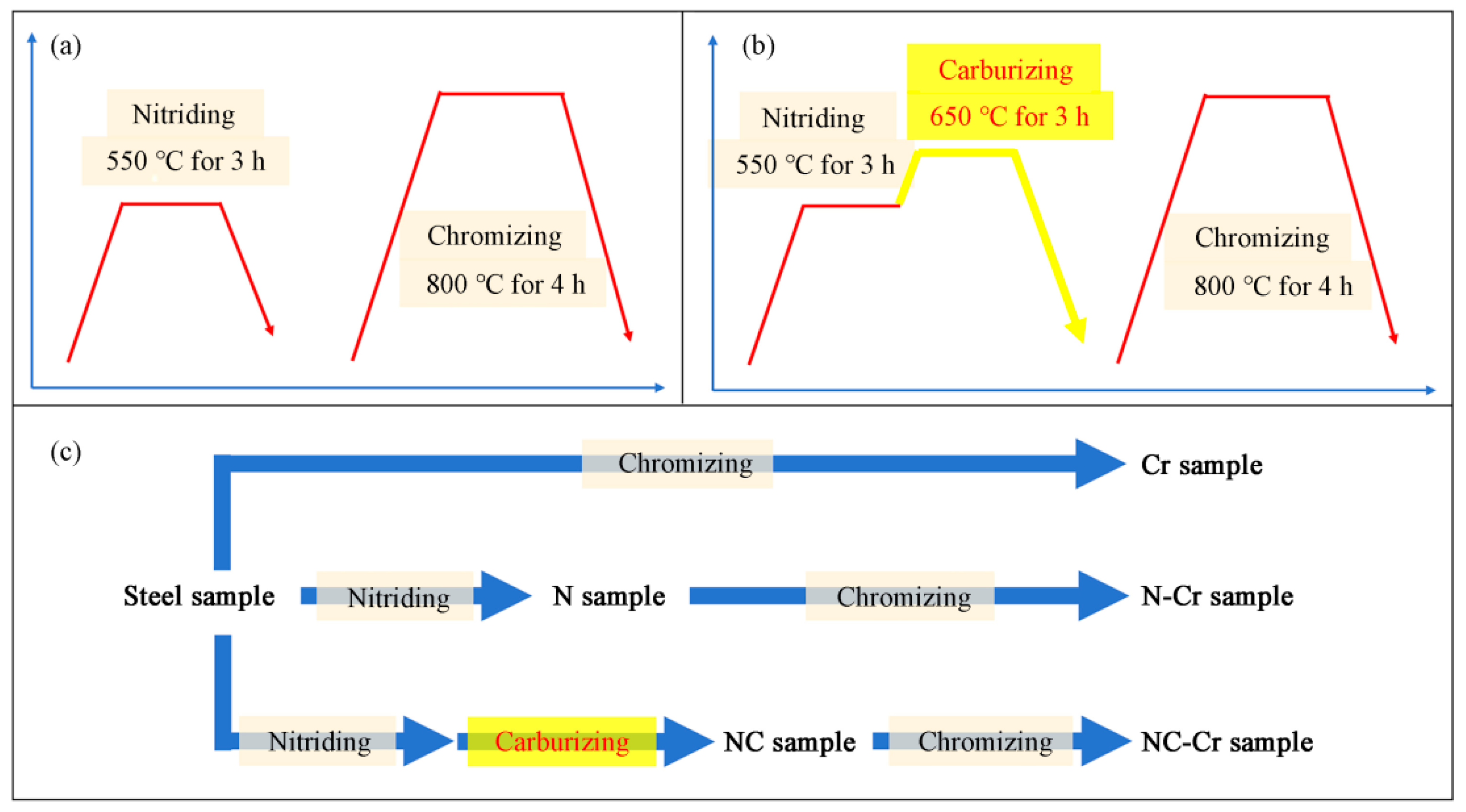
2.1. Sample Preparation

The substrate material used for this study is commonly used high-carbon steel, with a composition of Fe-0.65C-0.20Si-0.9Mn-0.01Cr-0.01Ni-0.001S-0.001P. The hot-rolled steel strips are treated by homogenizing annealing and then cut into samples with a dimension of 15 mm × 20 mm × 3 mm. All samples were polished with 4000-grit sandpaper to a roughness of approximately 20 nm, followed by ultrasonic cleaning. Then the following six schemes of surface treatment were operated for samples: Cr, which corresponds to direct chromizing; N-Cr, corresponding to the normal nitro-chromizing process as shown in Figure 1a; NC-Cr, corresponding to the optimized nitro-chromizing process with additional carburizing as shown in Figure 1b; N, corresponding to only nitriding; NC, corresponding to nitriding and additional carburizing; and steel, without any surface treatment. The procedures for the six groups of samples are shown in Figure 1c.
Plasma nitriding was carried out in a bell-type furnace at 550 °C for 3 h, with a total pressure of about 500 Pa and a mixed gas atmosphere of 60% H2 and 40% N2. The N sample and N-Cr sample were furnace-cooled after nitriding. The NC sample and NC-Cr sample were further carburized in the same furnace after nitriding. Carburizing was performed at 650 °C for 3 h, with a total pressure of about 1000 Pa and a gas mixture of 75% H2 and 25% CO2. After carburizing, the samples were furnace-cooled. Chromizing was carried out using pack cementation for 4 h at 800 °C. The powder mixture for chromizing consists of Al2O3, NH4Cl, and chromium powder. After chromizing, the samples were air-cooled.

2.2. Characterization and Performance Test Methods

The surface hardness tests were performed using a standard Vickers hardness tester (Shanghai optical instrument factory, Shanghai, China) in a load range of 50–1000 g. The adhesion strength is characterized using a standard Rockwell hardness tester at a load of 150 Kg. The tribological tests were conducted based on ASTM G99 using a ball-on-disc type tribometer (RTEC Instruments, San Jose, CA, USA) at room temperature with an Al2O3 ball (4 mm in diameter) as the counterpart, a normal force of 10 N, a rotational speed of 400 r/min, a rotation diameter of 6 mm, and a sliding time of 30 min. The wear tracks were collected using the Bruker Dektak 3D model Stylus Profiler.
The phase compositions of the samples were identified by a RIGAKU Smartlab 9 kW X-ray diffractometer (XRD, Rigaku, Tokyo, Japan) with Cu Kα radiation (1.5410 Å wavelength). The 2θ angle for measuring is in the range of 30° to 80° with a step size of 0.01°. The surface morphologies, wear tracks, and element contents were characterized by an FEI Nano 450 scanning electron microscope (SEM, FEI, Portland, OR, USA) equipped with an energy-dispersive X-ray spectrometer (EDS) probe.

3. Result and Discussion

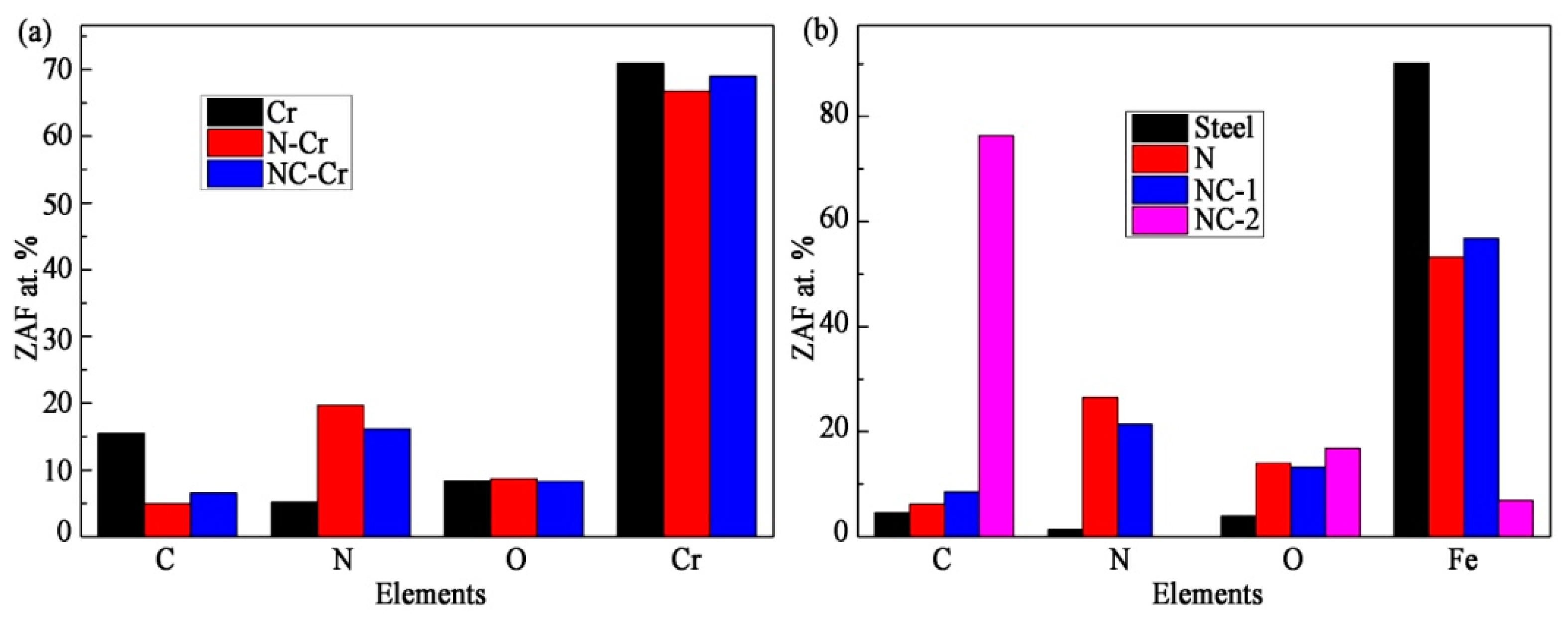
3.1. Phase Analysis and Microstructure Characteristics

Figure 2a shows the phase compositions on the surface of various chromized samples through XRD patterns. The surface of the Cr sample prepared by direct chromizing is mainly composed of the Cr7C3 phase. A small amount of Cr2N is also detected on the Cr sample. The main phase on the surface of the N-Cr sample prepared by normal nitro-chromizing is the Cr2N phase (PDF # 35-0803). A small amount of the Cr7C3 phase and CrN phase are present on the N-Cr sample. The strongest peak of Cr2N in the N-Cr sample is located at 40.19°. The phase compositions on the surface of the NC-Cr sample prepared by the optimized nitro-chromizing process with additional carburizing are similar to those of the N-Cr sample, except that the strongest peak of Cr2N is at 42.61°. The peak of 42.61° is the simultaneous response peak of Cr2N and Cr7C3, which indicates that the Cr7C3 phase content on the NC-Cr sample is greater than that on the N-Cr sample.
XRD patterns of the samples before chromizing, shown in Figure 2b, were obtained to understand the phase evolution during chromizing. The steel sample presents a typical pattern of the α-Fe phase. Then, the Cr sample mainly experiences the phase transformation of α-Fe + 3[C]dis + 7[Cr] → Cr7C3 + α-Fe during chromizing. [Cr] is the active chromium atom generated from chromium powders. The [C]dis are the carbon atoms dissolved in the α-Fe phase. The N sample prepared by nitriding exhibits a classical pattern of the Fe4N phase. The N-Cr sample mainly experiences the phase transformation of Fe4N + 2[Cr] → Cr2N + 2α-Fe during chromizing. The surface of the NC sample prepared by nitriding and additional carburizing is composed of Fe4N and α-Fe phases. It means that part of the Fe4N phase formed in the nitriding process will be transformed into the α-Fe phase during carburizing. It has been reported that as the temperature increases, the nitrogen atoms in Fe4N will diffuse into the inner substrate [34,35] and escape from the surface in the form of N2 [42,43,44]. Then the nitrogen content on the surface of the NC sample will decrease, leading to the formation of α-Fe. The α-Fe phase will transform into Cr7C3 during chromizing, which is verified by the XRD patterns of the Cr sample and steel sample. Therefore, the NC-Cr sample originated from the NC sample exhibits more Cr7C3 phase content than the N-Cr sample.
The surface morphologies of samples are shown in Figure 3. The direct chromized (Cr) sample exhibits many small particles with a size of 0.57 ± 0.21 μm and many black gaps. These particles are not closely adjacent to each other. These small particles and gaps are attributed to the insufficient phase transformation under the relatively low chromizing temperature of 800 °C. The N-Cr sample and NC-Cr sample, respectively, exhibit closely adjacent grains with sizes of 1.01 ± 0.05 μm and 1.04 ± 0.13 μm on their surfaces. It confirms that the Fe4N phase formed by nitriding (as shown in Figure 2) can accelerate the formation of the chromizing layer. Some gaps between grains appear on the N-Cr sample, while few gaps can be found on the NC-Cr sample. Compared to the N-Cr sample, the NC-Cr sample presents more bright zones, which indicate slopes of protrusion. The uneven surface morphology of the NC-Cr sample results from the two different phase transformations, which are respectively induced by the Fe4N and α-Fe phases.
Before chromizing, only slight polishing scratches are found on the surface of the steel sample shown in Figure 3d. Due to the formation of N2 [42,43,44], many pores form on the nitriding surface and result in a classical porous structure for the N sample (Figure 3e). The NC sample exhibits a more severe porous structure than the N sample, which can be attributed to the stronger N2 gas escape effect under the higher holding temperature during the additional carburizing. Moreover, some gray amorphous sediments appear on the pores of the NC sample, which are similar in morphology to amorphous graphite. Therefore, the additional carburizing can induce a severe porous nitriding structure with some gray amorphous sediments on the surface of the NC sample and also lead to an uneven morphology with closely adjacent grains after chromizing.
The EDS analysis on the surface of the chromized samples and the samples before chromizing are respectively shown in Figure 4a,b. The carbon content of the Cr sample is significantly higher than that of the N-Cr sample and the NC-Cr sample. Because chromium is a strong carbide-forming element, the carbon atoms in the inner substrate are easily diffused to the surface under the attraction of chromium and then form the Cr7C3 phase on the Cr sample. Compared with the N-Cr sample, the additional carburizing results in a slightly increased carbon content in the NC-Cr sample. Overall, similar element compositions are present in the NC-Cr sample and the N-Cr sample, which is consistent with the similar phase compositions of the two samples in Figure 2.
Before chromizing, the surface of the steel sample was mainly composed of the iron element. Compared to the steel sample, the nitrogen content of the N sample significantly increases. Compared with the N sample, the additional carburizing only results in a slightly increased carbon content in the NC sample. The EDS point analysis of the gray amorphous sediment shown in Figure 3f presents a result mainly composed of the carbon element. Taking into account the morphology and the element composition, the gray amorphous sediments can be identified as fine graphite sheets.
According to the comprehensive analysis of Figure 2, Figure 3 and Figure 4, the N sample undergoes the following phase transformation after carburizing: Fe4N + 2[C]int→ 2α-Fe + [C]dis + [C]graphite + [N]. The [C]int is the active carbon atom introduced by carburizing. The [C]graphite is a fine graphite sheet. [N] is the active nitrogen atom, which can diffuse to the inner substrate and also escape from the surface in the form of N2 [42,43,44].

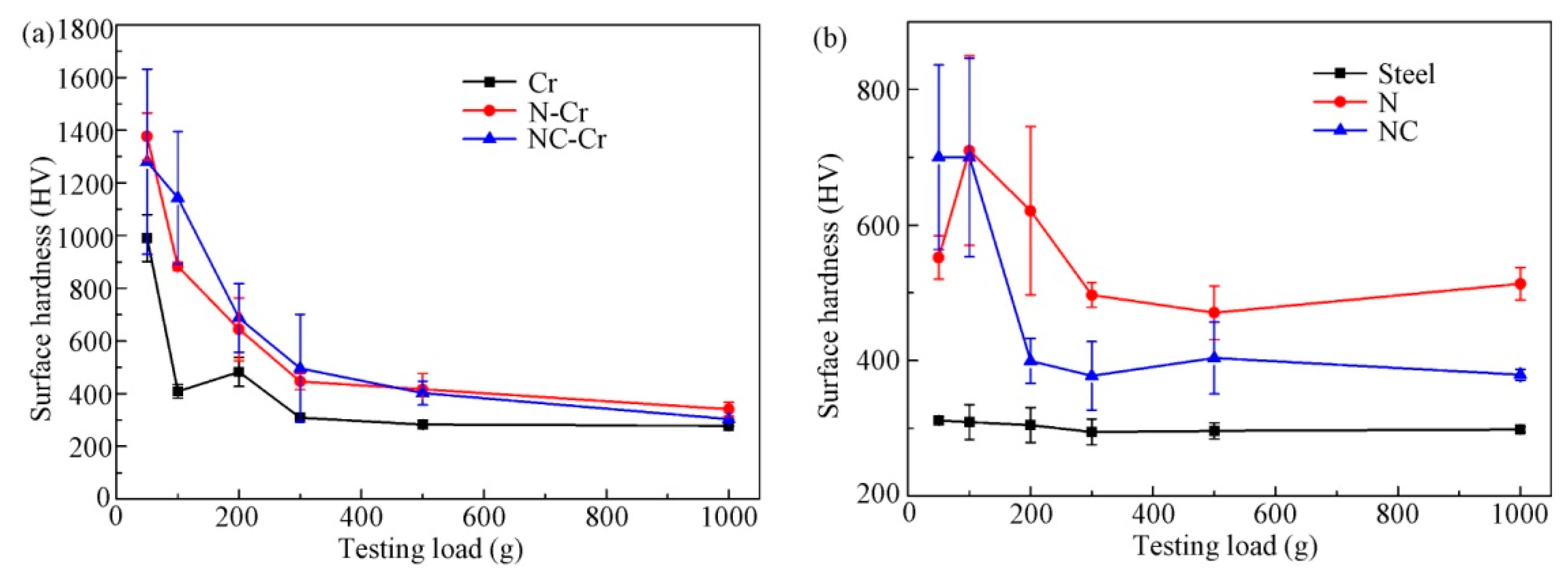
3.2. Surface Hardness and Adhesion Strength

The differences in the microstructures of various chromizing layers will affect their static mechanical properties, such as surface hardness and adhesion strength. The comprehensive hardness information of different depths in the sample can be obtained by the surface hardness tests under different loads. The smaller load can reflect the hardness information of areas that are closer to the surface.
Figure 5a shows that the surface hardness values of all chromized samples decrease with increasing loads. A similar phenomenon usually occurs in cases [34] with a hard surface layer and a soft inner substrate. The difference in hardness values of various chromized samples is relatively small under a load of 1000 g. The surface hardness of the Cr sample is approximately 1000 HV under a load of 50 g. This sample exhibits a maximum hardness decrease of 60% between 50 and 100 g loads. When the load increases to 200 g, the surface hardness of the Cr sample increases again to 500 HV. It suggests that a soft zone exists at the subsurface layer of the Cr sample. The soft subsurface layer is associated with the reported decarburized layer [4], accompanied by conventional direct chromizing. The decarburized layer is caused by the diffusion of carbon atoms from the subsurface layer towards the surface. The hardness of the N-Cr sample is approximately 1400 HV under a 50 g load. The maximum hardness decrease for this sample is about 36% between 50 and 100 g loads. The hardness of the NC-Cr sample is approximately 1300 HV under a 50 g load, with a large standard deviation. The deviation can be attributed to the uneven surface, as shown in Figure 3c. When the load increases to 100 g, the surface hardness of NC-Cr is approximately 1100 HV, only decreasing by 15%. Then the NC-Cr sample exhibits the maximum hardness decrease between 100 and 200 g loads. Taking into account the information under 50 and 100 g loads, the hardness values of the chromized samples have the following order: NC-Cr sample > N-Cr sample > Cr sample. The hardness values of the NC-Cr sample display the gentlest decreasing trend with increasing loads.
The hardness values of the pre-treated samples before chromizing are shown in Figure 5b. The steel sample has stable hardness values under various loads. The N sample displays a low hardness value of 550 HV at 50 g load and a high hardness value of 700 HV at 100 g load, resulting from the porous nitriding structure as shown in Figure 3e. The hardness values of the NC sample are 700 HV at both 50 and 100 g loads, indicating good performance for the outside layer on the surface. As confirmed by Figure 3f, the NC sample exhibits a more severe porous structure than the N sample, which is adverse to its good performance. However, the fine graphite sheets deposited at the pores of the nitriding layer can, to some extent, fill the pores and offset the negative impact of porous structure on hardness performance.
The adhesion strength of the surface layer is measured by the Rockwell hardness indentation method [45]. Figure 6 shows the Rockwell hardness indentations with different degrees of deformation and cracks. Obvious circular cracks and fine radial cracks appear around the indentation of the Cr sample. Only obvious radial cracks appear around the indentation of the N-Cr sample. For the NC-Cr sample, no obvious circular or radial crack displays around the indentation. According to the crack morphologies, it can be determined that the Cr sample is most prone to cracking induced by an external load, followed by the N-Cr sample. It is difficult to form cracks in the surface layer of the NC-Cr sample. Therefore, the adhesion strength of the chromized samples is in the following order: NC-Cr sample > N-Cr sample > Cr sample. Before chromizing, many wrinkles related to plastic deformation appear around the indentation of the steel sample. A small number of circular cracks display around the indentation of the N sample, while no circular crack presents around the indentation of the NC sample. This indicates that the NC sample obtains a better adhesion strength than the N sample through the additional carburizing process.

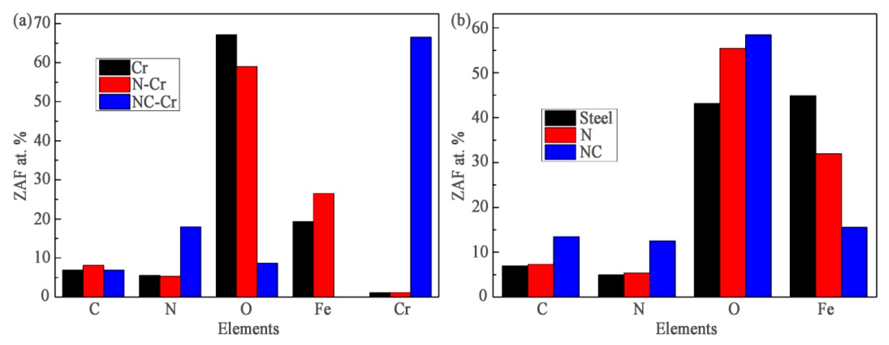
3.3. Wear Resistance

Although the NC-Cr sample has better static mechanical properties than the other chromized samples, the performance of wear resistance attracts more attention in industrial applications. Figure 7 displays the wear behaviors of all samples under a load of 10 N. The sectional line profiles of wear tracks are shown in Figure 7a,b. The wear rate (Kc) was calculated by using the following formula [46]: Kc = (2πR × A)/(F × S), where R and A are, respectively, the radius and the cross-section area of the wear track. F is the normal load, and S is the total sliding distance. In Figure 7c,d, the wear rates of the chromized samples have the following order: N-Cr sample > Cr sample > NC-Cr sample. Before chromizing, the samples have the following order of wear rate: steel sample > N sample > NC sample. Overall, the wear rates of the Cr sample and N-Cr sample are greater than those of the steel sample, while the N sample, NC sample, and NC-Cr sample exhibit better wear resistance than the steel sample. Among all samples, the NC-Cr sample displays the best wear resistance.
The comparison of the friction coefficients for various samples is shown in Figure 8. Due to the influence of the different roughness of the samples, only the friction coefficient results detected after 5 min of the tribological tests are used for analysis. The friction coefficient values of the Cr sample and N-Cr sample are close to 0.35, while the friction coefficient values of the NC-Cr sample are approximately 0.30. At the same time, the friction coefficient curve of the NC-Cr sample is smoother than that of the Cr sample and the N-Cr sample. Before chromizing, the friction coefficient values of the steel sample were approximately 0.4. The N sample displays friction coefficient values of approximately 0.35, which are consistent with the reported nitriding layer [47]. When the tribological test is conducted for 5 min, the friction coefficient value of the NC sample is approximately 0.10. This low friction coefficient is consistent with the wear behavior of graphite [38]. As the testing time prolongs, the friction coefficient values of the NC sample continue to increase. It has been confirmed that the NC sample has a combined surface structure of porous nitrides and fine graphite sheets (Figure 3f). Then the fine graphite sheets can induce low friction coefficient values in the early stages of the tribological test. As the test time prolongs, the graphite sheets gradually consume, resulting in the gradually increased friction coefficient values of the NC sample.
The SEM morphologies of the wear tracks, as shown in Figure 9, are characterized to understand wear behaviors in tribological tests. There are significant differences in the wear characteristics of each sample. The wear track of the Cr sample reveals coarse plowing grooves related to severe abrasive wear and some dark transfer films related to adhesive wear. Similar wear characteristics also occur on the wear track of the N-Cr sample. The worn surface of the NC-Cr sample is very smooth, without obvious grooves. Some dark transfer films imply that slight adhesive wear occurs on the NC-Cr sample. Before chromizing, large transfer films and some plowing grooves appear on the worn surface of the steel sample. The smooth, worn surface with a few fine plowing grooves on the N sample reveals slight abrasive wear. The worn surface of the NC sample is also smooth. Obvious scratches and fatigue cracks on the NC sample, respectively, indicate slight abrasive wear and severe fatigue wear.
The element compositions of the wear tracks are detected by the EDS analysis method and shown in Figure 10. For the worn surfaces of the Cr sample and N-Cr sample, the iron contents are relatively high, while the chromium contents are almost nonexistent. This indicates that the chromizing layers on these two samples have worn out. The prominent oxygen contents indicate severe oxidation wear on these two samples. The NC-Cr sample has high chromium and nitrogen content on the wear track, indicating that the chromizing layer of this sample has good wear resistance. Meanwhile, the oxygen content on the worn surface of the NC-Cr sample is relatively low, which confirms the viewpoint that the chromizing layer has strong oxidation resistance [9,10,11]. The high oxygen contents on the worn surface of the samples before chromizing also indicate severe oxidation wear. The high contents of nitrogen and carbon elements on the worn surface of the NC sample demonstrate that the wear loss is relatively low.
Taking into account Figure 9 and Figure 10, it can be determined that the main wear mechanisms of the steel sample are severe adhesive wear and oxidation wear. The Cr sample and N-Cr sample exhibit similar wear mechanisms, including severe abrasive wear, adhesive wear, and oxidation wear. The N sample suffers slight abrasive wear and oxidation wear. The severe fatigue wear and oxidation wear are responsible for the wear rate of the NC sample. Only slight adhesive wear occurs on the NC-Cr sample.

3.4. The Effect of the Additional Carburizing Process on the Wear Resistance

Compared with the steel sample, the N-Cr sample and Cr sample exhibit higher hardness and poorer wear resistance. The poor wear resistance is attributed to the severe abrasive wear that can be activated by the debris. However, the poor adhesion strength of the N-Cr sample and the Cr sample shown in Figure 6 can easily cause cracks and debris. The debris originating from the hard outside layer will exacerbate the wear loss of the inner soft substrate through the mechanism of abrasive wear. In this instance, the high hardness of the N-Cr sample and the Cr sample would accelerate the wear rate. Therefore, the unsatisfactory wear resistances of the N-Cr sample and the Cr sample are caused by the poor adhesion strength.
It is worth mentioning that the N-Cr sample has a slightly lower friction coefficient, higher surface hardness, and better adhesion strength compared to the Cr sample, but the wear rate of the N-Cr sample is greater than that of the Cr sample. According to the analysis of the worn surface in Figure 9, both the N-Cr sample and the NC-Cr sample exhibit severe abrasive wear, which is derived from the debris detached from the brittle chromium nitrides/carbides. On the one hand, compared to the Cr sample, the N-Cr sample will produce debris with higher hardness, resulting in more severe abrasive wear on the inner substrate. On the other hand, because the active nitrogen atoms in steel are prone to generating N2 pores at high temperatures [42,43,44], it is difficult for the N-Cr sample to avoid the formation of inner N2 pores during chromizing at 800 °C. The reported works also display these inner pores [28,30,32]. These inner pores will make the N-Cr sample more prone to generating cracks and debris, thereby exacerbating abrasive wear. Although the N-Cr sample has slightly lower friction coefficients than the Cr sample, the influence of low friction coefficients on abrasive wear is smaller than that on adhesive wear. Overall, due to the brittle nature of chromium nitrides/carbides and the formation of N2 pores at high temperatures, the N-Cr sample suffers more severe abrasive wear than the Cr sample.
The chromizing layers of both the N-Cr sample and the NC-Cr sample have similar surface hardness under a load of 50 g and a similar main phase composition of Cr2N and Cr7C3. However, the wear rate of the NC-Cr sample is about 1/15 of that of the N-Cr sample. The NC-Cr sample suffers from an additional carburizing process compared to the N-Cr sample. It has been demonstrated that fine graphite sheets would form on the porous nitriding structure after carburizing. On the one hand, these graphite sheets can transform into Cr7C3 phases through the phase transformation of 3[C]graphite + 7[Cr] → Cr7C3 during chromizing. These Cr7C3 phases can fill the porous structure along with the retained graphite sheets, thereby improving the adhesion strength of the NC-Cr sample. On the other hand, some retained graphite sheets play a lubricating role, causing the low friction coefficient of the NC-Cr sample (Figure 8). So, the fine graphite sheets can have good adhesion strength and a low friction coefficient, resulting in good wear resistances in the NC-Cr sample and NC sample. Overall, the optimized nitro-chromizing process with additional carburizing, as shown in Figure 1b, can effectively avoid the poor wear resistance associated with the normal nitro-chromizing process, as shown in Figure 1a.

4. Conclusions

In this work, an optimized nitro-chromizing strategy with additional carburizing was proposed to improve the wear resistance of nitro-chromized carbon steel. Comparative analyses of various chromized samples and the corresponding samples before chromizing were conducted in terms of phase composition, microstructure, and mechanical property characterizations. The main conclusions are as follows:
(1) Both the chromizing layers prepared by the optimized nitro-chromizing process and the normal nitro-chromizing process have similar main phase compositions of Cr2N and Cr7C3. Under a load of 100 g, the surface hardness of an optimized nitro-chromized sample is approximately 1100 HV, which is higher than that of a normal nitro-chromized sample.
(2) The normal nitro-chromized sample exhibits severe abrasive wear, which is due to the brittle nature of chromium nitrides/carbides and the formation of N2 pores at high temperatures. However, the additional carburizing brings a low wear rate for the optimized nitro-chromized sample, which is only 1/15 of that for the normal nitro-chromized sample.
(3) The additional carburizing in the optimized nitro-chromizing process can induce the fine graphite sheets deposited on the porous nitriding structure. These graphite sheets can fill the porous structure and reduce the friction coefficient, thus resulting in good adhesion strength and excellent wear resistance for an optimized nitro-chromized sample.

Author Contributions

Conceptualization, Y.H.; Methodology, Y.H.; Software, S.H.; Validation, S.H.; Formal analysis, B.D.; Resources, S.H.; Data curation, Y.Y.; Writing—original draft, Y.Y.; Writing—review & editing, B.D., W.X. and T.F.; Visualization, C.H.; Supervision, T.F.; Project administration, C.H.; Funding acquisition, W.X. All authors have read and agreed to the published version of the manuscript.

Funding

This work is supported by the Guangdong Academy of Sciences Project of Science and Technology Development (2020GDASYL-20200103109), the Guangdong Basic and Applied Basic Research Foundation (2019A1515110710, 2021A1515012086), the Hunan Natural Science Foundation Project (2023JJ50320), and the Hunan Provincial College Student Innovation and Entrepreneurship Training Program (S202311528129).

Institutional Review Board Statement

Not applicable.

Informed Consent Statement

Not applicable.

Data Availability Statement

The authors confirm that the data supporting the findings of this study are available within the article.

Conflicts of Interest

The authors declare no conflict of interest.

References

  1. Tabrizi, A.T.; Aghajani, H. Study through diverse synthesis methods of chromium nitride thin layers: Areview. J. Surf. Investig. 2021, 15, 1217–1224. [Google Scholar] [CrossRef]
  2. Tabrizi, A.T.; Aghajani, H.; Laleh, F.F. Tribological characterization of hybrid chromium nitride thin layer synthesized on titanium. Surf. Coat. Technol. 2021, 419, 127317. [Google Scholar] [CrossRef]
  3. Tabrizi, A.T.; Aghajani, H.; Laleh, F.F. Tribological study of thin-electroplated chromium: Evaluation of wear rate as a function of surface roughness. Exp. Tech. 2023, 47, 369–379. [Google Scholar] [CrossRef]
  4. Chang, D.Y.; Lee, S.Y.; Kang, S.G. Effect of plasma nitriding on the surface properties of the chromium diffusion coating layer in iron-base alloys. Surf. Coat. Technol. 1999, 116, 391–397. [Google Scholar] [CrossRef]
  5. Wei, Z.; Zhu, C.; Zhou, L.; Wang, L. The enhancement effect of salt bath chromizing for P20 steel. Coatings 2020, 11, 27. [Google Scholar] [CrossRef]
  6. Zhou, Y.; Zhang, H.; Wang, Y. Effect of Y2O3 on microstructure and oxidation of chromizing coating. Trans. Nonferrous Met. Soc. China 2008, 18, 1122–1127. [Google Scholar] [CrossRef]
  7. Lee, J.W.; Duh, J.G. Evaluation of microstructures and mechanical properties of chromized steels with different carbon contents. Surf. Coat. Technol. 2004, 177, 525–531. [Google Scholar] [CrossRef]
  8. Baggio-Scheid, V.H.; DeVasconcelos, G.; Oliveira, M.A.S.; Ferreira, B.C. Duplex surface treatment of chromium pack diffusion and plasma nitriding of mild steel. Surf. Coat. Technol. 2003, 163, 313–317. [Google Scholar] [CrossRef]
  9. Lin, N.; Xie, F.; Yang, H.; Tian, W.; Wang, H.; Tang, B. Assessments on friction and wear behaviors of P110 steel and chromizing coating sliding against two counterparts under dry and wet conditions. Appl. Surf. Sci. 2012, 258, 4960–4970. [Google Scholar] [CrossRef]
  10. Dong, Z.; Zhou, T.; Liu, J.; Zhang, X.; Shen, B.; Hu, W.; Liu, L. Cavitation erosion behaviors of surface chromizing layer on 316L stainless steel. Ultrason Sonochem. 2019, 58, 104668. [Google Scholar] [CrossRef]
  11. Lin, N.; Guo, J.; Xie, F.; Zou, J.; Tian, W.; Yao, X.; Zhang, H.; Tang, B. Comparison of surface fractal dimensions of chromizing coating and P110 steel for corrosion resistance estimation. Appl. Surf. Sci. 2014, 311, 330–338. [Google Scholar] [CrossRef]
  12. Hakami, F.; Heydarzadeh Sohi, M.; Rasizadeh Ghani, J. Duplex surface treatment of AISI 1045 steel via plasma nitriding of chromized layer. Thin Solid Film. 2011, 519, 6792–6796. [Google Scholar] [CrossRef]
  13. Lee, S.Y.; Kim, G.S.; Kim, B.S. Mechanical properties of duplex layer formed on AISI403 stainless steel by chromizing and boronizing treatment. Surf. Coat. Technol. 2004, 177, 178–184. [Google Scholar] [CrossRef]
  14. Grejtak, T.; Qu, J. Improving mechanical properties of carbon and tool steels via chromizing. Adv. Appl. Ceram. 2023, 1, 1–11. [Google Scholar] [CrossRef]
  15. Meng, T.; Guo, Q.; Xi, W.; Ding, W.; Liu, X.; Lin, N.; Yu, S.; Liu, X. Effect of surface etching on the oxidation behavior of plasma chromizing-treated AISI 440B stainless steel. Appl. Surf. Sci. 2018, 433, 855–861. [Google Scholar] [CrossRef]
  16. Bai, C.Y.; Wen, T.-M.; Hou, K.H.; Pu, N.W.; Ger, M.D. The characteristics and performance of AISI 1045 steel bipolar plates with chromized coatings for proton exchange membrane fuel cells. Int. J. Hydrog. Energy 2011, 36, 3975–3983. [Google Scholar] [CrossRef]
  17. Li, S.; Yang, Z.; Wan, Q.; Hou, J.; Xiao, Y.; Zhang, X.; Gao, R.; Meng, L. Increase in wear resistance of traction wheel via chromizing: A study combining experiments and simulations. Coatings 2022, 12, 1275. [Google Scholar] [CrossRef]
  18. Taktak, S.; Ulker, S.; Gunes, I. High temperature wear and friction properties of duplex surface treated bearing steels. Surf. Coat. Technol. 2008, 202, 3367–3377. [Google Scholar] [CrossRef]
  19. Cho, K.H.; Lee, W.G.; Lee, S.B.; Jang, H. Corrosion resistance of chromized 316L stainless steel for PEMFC bipolar plates. J. Power Sources 2008, 178, 671–676. [Google Scholar] [CrossRef]
  20. Chi, C.; He, Z.; Gao, Y.; Xu, Z. Thermodynamic analysis of carbon migration in W1-1.0C steel in plasma surface chromizing. J. Univ. Sci. Technol. Beijing 2006, 13, 131–134. [Google Scholar] [CrossRef]
  21. Lin, N.; Xie, F.; Zhong, T.; Wu, X.; Tian, W. Influence of adding various rare earths on microstructures and corrosion resistance of chromizing coatings prepared via pack cementation on P110 steel. J. Rare Earths 2010, 28, 301–304. [Google Scholar] [CrossRef]
  22. Djemmah, S.; Madi, Y.; Voué, M.; Haddad, A.; Allou, D.; Oualllam, S.; Bouchafaa, H.; Rezzoug, A. Effect of Mg addition on morphology, roughness and adhesion of crchromized layer produced by pack cementation. IJE Trans. A Basics 2023, 36, 1773–1782. [Google Scholar] [CrossRef]
  23. Wang, Z.; Lu, J.; Lu, K. Wear and corrosion properties of a low carbon steel processed by means of SMAT followed by lower temperature chromizing treatment. Surf. Coat. Technol. 2006, 201, 2796–2801. [Google Scholar] [CrossRef]
  24. Lu, S.; Wang, Z.; Lu, K. Enhanced chromizing kinetics of tool steel by means of surface mechanical attrition treatment. Mater. Sci. Eng. A 2010, 527, 995–1002. [Google Scholar] [CrossRef]
  25. Wang, Z.; Lu, J.; Lu, K. Chromizing behaviors of a low carbon steel processed by means of surface mechanical attrition treatment. Acta Mater. 2005, 53, 2081–2089. [Google Scholar] [CrossRef]
  26. Zeng, J.; Hu, J.; Yang, X.; Xu, H.; Li, H.; Guo, N. Evolution of the microstructure and properties of pre-boronized coatings during pack-cementation chromizing. Coatings 2020, 10, 159. [Google Scholar] [CrossRef]
  27. Hu, J.; Zeng, J.; Yang, Y.; Yang, X.; Li, H.; Guo, N. Microstructures and wear resistance of boron-chromium duplex-alloyed coatings prepared by a two-step pack cementation process. Coatings 2019, 9, 529. [Google Scholar] [CrossRef]
  28. Cao, H.; Luo, C.; Liu, J.; Zou, G. Phase transformations in low-temperature chromized 0.45 wt.% C plain carbon steel. Surf. Coat. Technol. 2007, 201, 7970–7977. [Google Scholar] [CrossRef]
  29. Cao, H.; Luo, C.; Liu, J.; Wu, C.; Zou, G. Formation of a nanostructured CrN layer on nitrided tool steel by low-temperature chromizing. Scripta Mater. 2008, 58, 786–789. [Google Scholar] [CrossRef]
  30. Wu, C.; Hong, Y.; Chen, W.; Chen, J.; Yuan, M.; Liao, X. A double strengthened surface layer fabricated by nitro-chromizing on carbon steel. Surf. Coat. Technol. 2016, 298, 83–92. [Google Scholar] [CrossRef]
  31. Hakami, F.; HeydarzadehSohi, M.; RasizadehGhani, J.; Ebrahimi, M. Chromizing of plasma nitrided AISI 1045 steel. Thin Solid Film. 2011, 519, 6783–6786. [Google Scholar] [CrossRef]
  32. Ozdemir, O.; Sen, S.; Sen, U. Formation of chromium nitride layers on AISI 1010 steel by nitro-chromizing treatment. Vacuum 2007, 81, 567–570. [Google Scholar] [CrossRef]
  33. Durmaz, M.; Kilinc, B.; Abakay, E.; Sen, U.; Sen, S. Tribological properties of CrN coatings deposited by nitro-chromizing treatment on AISI D2 steel. AIP Conf. Proc. 2015, 1653, 020034. [Google Scholar] [CrossRef]
  34. Chen, W.; Wu, C.; Liu, Z.; Ni, S.; Hong, Y.; Zhang, Y.; Chen, J. Phase transformations in the nitrocarburizing surface of carbon steels revisited by microstructure and property characterizations. Acta Mater. 2013, 61, 3963–3972. [Google Scholar] [CrossRef]
  35. Woehrle, T.; Leineweber, A.; Mittemeijer, E.J. Microstructural and phase evolution of compound layers growing on α–iron during gaseous nitrocarburizing. Metall. Mater. Trans. A 2012, 43, 2401–2413. [Google Scholar] [CrossRef]
  36. Nikolussi, M.; Leineweber, A.; Mittemeijer, E.J. Microstructure and crystallography of massive cementite layers on ferrite substrates. Acta Mater. 2008, 56, 5837–5844. [Google Scholar] [CrossRef]
  37. Yang, Y.; Yan, M.; Zhang, Y.; Zhang, C.; Wang, X. Self-lubricating and anti-corrosion amorphous carbon/Fe3C composite coating on M50NiL steel by low temperature plasma carburizing. Surf. Coat. Technol. 2016, 304, 142–149. [Google Scholar] [CrossRef]
  38. Yang, Y.; Yan, M.; Zhang, Y.; Li, D.; Zhang, C.; Zhu, Y.; Wang, Y. Catalytic growth of diamond-like carbon on Fe3C-containing carburized layer through a single-step plasma-assisted carburizing process. Carbon 2017, 122, 1–8. [Google Scholar] [CrossRef]
  39. Yang, Y.; Yan, M.; Zhang, Y. Tribological behavior of diamond-like carbon in-situ formed on Fe3C-containing carburized layer by plasma carburizing. Appl. Surf. Sci. 2019, 479, 482–488. [Google Scholar] [CrossRef]
  40. Yang, Y.; Li, J.; Zhang, Z.; Zhang, S.; Zhang, S.; Wang, Q. Characterization of microstructure and surface properties of GLC film deposited in plasma nitriding system. Diam. Relat. Mater. 2021, 119, 108570. [Google Scholar] [CrossRef]
  41. Li, J.; Men, S.; Zhang, Z.; Yang, Y.; Sun, Y.; Ding, J.; Wang, Q. Structural, mechanical, and tribological properties of GLC film on a nitrided layer prepared in a glow-discharge plasma nitriding system. Vacuum 2021, 193, 110543. [Google Scholar] [CrossRef]
  42. Dong, J.; Hoffmann, F.; Kluemper-Westkamph, H.; Zoch, H.W. Influence of CO or CO2 as carbon donator on the development of the compound layer during nitrocarburizing of alloyed steels. Mater. Perform. Charact. 2012, 1, 103926. [Google Scholar] [CrossRef]
  43. Li, S.; Manory, R.R. Surface morphology and compound layer pores of plasma nitrocarburized low carbon steel. Metall. Mater. Trans. A 1996, 27, 135. [Google Scholar] [CrossRef]
  44. Middendorf, C.; Mader, W. Growth and microstructure of iron nitride layers and pore formation in ε-Fe3N. Z. Metalldk. 2013, 94, 333–340. [Google Scholar] [CrossRef]
  45. Zamharir, M.J.; Aghajani, H.; Tabrizi, A.T. Evaluation of adhesion strength of TiN layer applied on 316L substrate by electrophoretic deposition. J. Aust. Ceram. Soc. 2021, 57, 1219–1230. [Google Scholar] [CrossRef]
  46. Schubert, T.; Löser, W.; Schinnerling, S.; Bächer, I. Alternative phase formation in thin strip casting of stainless steels. Mater. Sci. Technol. -Lond. 2013, 11, 181–185. [Google Scholar] [CrossRef]
  47. Hong, Y.; Dong, D.; Lin, S.; Wang, W.; Tang, C.; Kuang, T.; Dai, M. Improving surface mechanical properties of the selective laser melted 18Ni300 maraging steel via plasma nitriding. Surf. Coat. Technol. 2021, 406, 126675. [Google Scholar] [CrossRef]
Figure 1. The illustrations of the heat treatment for the N-Cr sample (a), the heat treatment for the NC-Cr sample (b), and the procedures for the six groups of samples (c).
Coatings 13 01858 g001
Figure 2. X-ray diffraction (XRD) patterns of the various chromized samples (a) and the samples before chromizing (b). The chromized samples include the Cr sample, the N-Cr sample, and the NC-Cr sample. The samples before chromizing include the steel sample, the N sample, andthe NC sample.
Coatings 13 01858 g002
Figure 3. The surface morphologies, respectively, correspond to the Cr sample (a), N-Cr sample (b), NC-Cr sample (c), steel sample (d), N sample (e), and NC sample (f).
Coatings 13 01858 g003
Figure 4. The element composition on the surface of the chromized samples (a) and the pre-treated samples before chromizing (b). NC-1 and NC-2, respectively, correspond to the porous structure and the amorphous sediments in the NC sample.
Coatings 13 01858 g004
Figure 5. The surface hardness of various chromized samples (a) and the pre-treated samples before chromizing (b) under different loads.
Coatings 13 01858 g005
Figure 6. The adhesion strengths of the Cr sample (a), N-Cr sample (b), NC-Cr sample (c), steel sample (d), N sample (e), and NC sample (f) measured by the Rockwell hardness indentation method.
Coatings 13 01858 g006
Figure 7. The wear tracks (a,b) and wear rates (c,d) for the samples. (a,c) The chromized samples (b,d) and the pre-treated samples before chromizing.
Coatings 13 01858 g007
Figure 8. The friction coefficients of the chromized samples (a) and the pre-treated samples before chromizing (b).
Coatings 13 01858 g008
Figure 9. The worn surface morphologies of the Cr sample (a), N-Cr sample (b), NC-Cr sample (c), steel sample (d), N sample (e), and NC sample (f).
Coatings 13 01858 g009
Figure 10. The element compositions on the worn surface of the chromized samples (a) and the pre-treated samples (b).
Coatings 13 01858 g010
Disclaimer/Publisher’s Note: The statements, opinions and data contained in all publications are solely those of the individual author(s) and contributor(s) and not of MDPI and/or the editor(s). MDPI and/or the editor(s) disclaim responsibility for any injury to people or property resulting from any ideas, methods, instructions or products referred to in the content.

