Article

Exploiting Surface Plasmon with Dielectric Coating in Copper Wires Waveguide for the Propagation of Terahertz Waves

by
Arslan Ahmed Sohoo
1,
Fauziahanim Che Seman
1,
Ahmed Jamal Abdullah Al-Gburi
2,*,
Hamza Ahmad
3,
Yee See Khee
1,
Nurul Syafeeqa Binti Ishak
1,
Thamer A. H. Alghamdi
4,5,* and
Moath Alathbah
6
1
Research Center for Applied Electromagnetic (EMCenter), Institute of Integrated Engineering, Universiti Tun Hussein Onn Malaysia, Parit Raja 86400, Malaysia
2
Center for Telecommunication Research & Innovation (CeTRI), Fakulti Teknologi dan Kejuruteraan Elektronik dan Komputer (FTKEK), Universiti Teknikal Malaysia Melaka (UTeM), Jalan Hang Tuah Jaya, Durian Tunggal 76100, Malaysia
3
Department of Electrical Engineering, University of Engineering and Technology, Mardan 23200, Pakistan
4
Wolfson Centre for Magnetics, School of Engineering, Cardiff University, Cardiff CF24 3AA, UK
5
Electrical Engineering Department, School of Engineering, Albaha University, Albaha 65779, Saudi Arabia
6
Department of Electrical Engineering, College of Engineering, King Saud University, Riyadh 11451, Saudi Arabia
*
Authors to whom correspondence should be addressed.
Coatings 2023, 13(11), 1857; https://doi.org/10.3390/coatings13111857
Submission received: 29 August 2023 / Revised: 25 October 2023 / Accepted: 27 October 2023 / Published: 29 October 2023

Abstract

:
Recently, metallic wires have gained popularity for utilization as waveguides in propagating sub-THz and THz waves through surface plasmonic polaritons (SPPs). Single and double metallic wire waveguides have demonstrated the ability to propagate these high frequencies with minimal loss and nearly zero dispersion. However, wires typically installed commercially are often coated with dielectric material. Therefore, this paper investigated the effects of using two and four metallic copper wires, both with and without dielectric coating. The impact of various gap distances on different propagation characteristics was also analyzed. Computer Simulation Technology (CST) Microwave Studio was employed in this study for electromagnetic simulations of both uncoated and coated configurations of two and four wires. The introduction of a dielectric coating led to an enhancement in reducing conductor losses and improving energy confinement, with the goal of enhancing the overall efficiency of waveguide signal propagation.

1. Introduction

With the increase in the number of devices, users, and new applications, the demand for high bandwidth and high data rates has also risen. In both wired and wireless communication systems, there is no indication of a decrease; on the contrary, it continues to grow due to the rise of data-intensive applications and emerging technologies. One approach to enhancing data rates is to venture into higher frequency ranges. Beyond 6 GHz, a broad spectrum remains unexplored, offering potential for applications and technology development. The sub-THz and THz bands are two such unexplored frequency ranges that have gained prominence. Recently, the THz range has become an appealing and rapidly evolving field of communication research, piquing the interest of scientists and researchers from various disciplines. THz waves are electromagnetic waves with frequencies falling between the infrared and microwave regions of the electromagnetic spectrum, spanning from 0.1 to 10 THz [1].
The Federal Communication Commission (FCC) recently made the THz spectrum available for testing without a license, which encouraged studies around the world to examine the spectrum’s possibilities [2]. The THz spectrum will also be used by future technologies, such as 6G, which is currently in testing [3]. THz will no doubt bring a technological revolution and change human living standards. Additionally, the THz range can improve accuracy in imaging and sensing various objects with fine details, making it beneficial for quality assurance, medical imaging, security screening, and imaging [4].
In 2018, John Cioffi brought out the new concept of using these current twisted pair copper bundles to transmit high frequencies like the THz band. He introduced the terabit digital subscriber line (TDSL) concept, which wirelessly transmits THz waves across these already-installed twisted pair lines using higher order modes, including transverse electric (TE) and transverse magnetic (TM) modes [5]. This idea of achieving the data rate in terabits per second (Tbps) created hype in this area, and researchers started to explore and work on the realization of TDSL. Various theoretical as well as experimental campaigns were carried out to analyze different THz components’ and devices’ feasibility to be utilized in the TDSL, such as copper binder analysis [6], narrow circular waveguides [7,8,9], antenna coupling impact, and so on.
The fundamental concept for THz guiding in metal-wire waveguides is the propagation of THz surface plasmon polaritons (SPPs), which are very sensitive to the metal surface conditions [10]. Localized surface electromagnetic waves called surface plasmon polaritons (SPPs) propagate over a metal–dielectric contact. The diffraction limit can be overcome, photonic components can be miniaturized, and highly integrated optical components and circuits can be developed with SPPs due to their capacity to confine light at a subwavelength scale with high intensity. The development of efficient plasmonic circuits is still loaded with challenges. The primary challenges are the lack of efficient functional plasmonic devices, such as high-efficiency waveguides with minimal propagation and bending losses, high-efficiency plasmonic connections between devices, and high-efficiency excitation, etc.

2. Literature Review on THz Guiding Properties in Metal-Wire Waveguides

A metallic single-wire waveguide (SWWG) generally known as ‘Sommerfeld wire’ can propagate the THz pulses virtually with low attenuation, near-zero dispersion, and remarkable structure simplicity [11]. The metallic wire waveguides can support the propagation of higher-order modes. However, these modes experience a much higher attenuation constant, and after a short distance, they tend to support a single mode. Wang, in 2004, first demonstrated the propagation of THz waves through stainless steel with a 0.9 mm diameter; he successfully propagated the THz waves with an attenuation constant of less than 0.03 dB per centimeter, as well as with almost no dispersion in the frequency range of 250 GHz to 750 GHz [11]. Additionally, he also developed the THz endoscope using metallic wires. These single-wire waveguides support transverse magnetic (TM) mode, i.e., TM01, which is a quasi-TEM mode that is similar to the propagation constant and polarization of coaxial cables [12]. There are some major drawbacks of single SWWG that are important to consider, such as the fact that the performance of these waveguides is enormously sensitive to perturbations such as bending, which leads to the poor confinement of the modes around the wire and waves leaking as radiation upon bending [13]. The reduction in the losses and waves leakage in a single metallic wire with different bends using the dielectric coating was analyzed by Berenguer et al. [12]. Additionally, the coupling efficiency of the single-wire waveguide is very low. Commonly available THz sources, such as the photoconductive antenna (PCA), emit linearly polarized THz radiations that cannot efficiently excite the fundamental mode, which is radially polarized in the case of SWWGs [14].
Two-wire waveguides (TWWGs) are made up of two metal wires with an air gap or dielectric gap between them. They can be directly excited by a simple terahertz (THz) dipole source [15] as long as the polarization of the source is parallel to the line connecting the centers of the wires. This is because the field distribution of the fundamental transverse electromagnetic (TEM) mode in a TWWG resembles that of a dipole. In contrast to the weakly guided Sommerfeld wave of a single wire, the efficient confinement of the modal energy between the two wires makes TWWGs more tolerant to bending losses [16]. Various metallic materials, such as copper, silver, steel, gold, etc., were compared and analyzed for efficient propagation of THz waves [1]. A theoretical study on the two-wire waveguide for efficient propagation of THz waves was carried out in [17], and the efficient coupling of THz radiations into the airgap between two metallic wires was investigated experimentally by exciting the piece of gallium arsenide (GaAs) inside the waveguide [18], achieving a low loss of 1 dB/cm. The propagation of THz waves through the two-wire power line was studied in [19], and for the TDSL realization, experimental validation was performed by Rabi Shrestha in 2020. He estimated an achievable data rate of 10 Tbps for 3 m [20]. In 2022, J. Dong introduced the realization of THz signal processing through four brag-grated parallel wires. THz wave guidance through the metallic wires is based on the propagation of SPP through the metal–air interface, and by introducing periodic grating, manipulation of SPP was used to achieve polarization division multiplexing [10]. Bare wires have some limitations, such as radiation loss and low confinement with bending [13]; therefore, a dielectric coating is applied to mitigate these limitations. Coated metallic wires are generally known as ‘Goubau Lines’ or ‘G-Lines’, as G. Goubau invented them in the early 1950s to reduce the radial extent of the field and dimension of the excitation device [21]. Several studies have also been carried out for theoretical analysis and modes on dielectric-coated waveguides [22,23]. The interface of bare copper wire with air or any other material and its roughness level can manipulate the SPP propagating through it and introduce considerable effects to the propagation characteristics of THz waves. Therefore, for efficient propagation, the interaction of dielectric coating with bare copper wire is crucial to study and analyze.

3. Design Methodology of Two- and Four-Wire Waveguide

In this study, the effect of dielectric coating on the bare metallic copper wires and their interaction with each other at different gap sizes were studied to analyze the feasibility of utilizing copper wires in the THz range. Commercially available finite element modeling (FEM) software CST Microwave Studio 2022 [24] was used for simulation analysis using a time domain solver. The length of the wire was kept at 20 mm to save on simulation time and computation resources. The details of the simulation parameters are mentioned in Table 1. A total of 1000 samples were taken for a proposed band from 220 to 320 GHz, with a step size of 100 MHz. The cells per wavelength were increased to ensure the accuracy of the simulations. The computation time varied, as background activities also delayed the simulation. The incident radiations to the waveguide were linearly polarized, and an E-field vector was directed to the plane parallel to the length of the waveguide. The radius ‘a’ of the wire was 0.5 mm, while the outer radius ‘b’ was 0.6 mm after applying a dielectric coating with a thickness of 100 µm. The 3D models of the proposed wire waveguides, with and without coating, are shown in Figure 1.
The above schematic illustration shows several wire waveguides under analysis: (a) two Sommerfeld wires (uncoated) and two dielectric coated wires (Goubau lines) in (c). The wire radius ‘a’ and the wire radius with coating thickness ‘b’ are indicated in the cross-section view of wires in (b) and (d). The material properties, such as conductivity of copper σ, relative permittivity of the dielectric coating of the wire ε d , and ε d for the air relativity, are also shown in the cross-section view. Four-wire waveguide bare and coated wires are shown in (e) and (f), respectively, while d is the distance between two copper wires. The conductivity of the copper wire is σ = 5.57 × 10⁷ S m−1, loss tangent tan δ = 1 × 10⁻⁴, and the coating of the copper wire is Polytetrafluoroethylene (PTFE) with a dielectric constant of 2.02, a refractive index of 1.4, and a loss tangent tan δ = 0.00022 [25,26].
Attenuation constant is an important parameter for efficient propagation of THz signal at long range. At such a high-frequency range, the losses are increased, leading to high attenuations. The attenuation constant (α) arises from various loss mechanisms and is a combination of dielectric attenuation (αd) and conductor attenuation (αc) losses; α = αc+ αd. The analytical approach for the one and two Sommerfeld and Goubau wires is also discussed. The characteristic equation for the uncoated single wires is given in Equation (1) [21,26,27].
γ H 0 1 ( γ a ) γ H 1 1 ( γ a ) = γ c J 0 1 ( γ c a ) ϵ c J 1 1 ( γ c a )
where γ H 0 1,2 ( γ ρ ) = J 0 ( γ ρ ) ± i Y 0 ( γ ρ ) and the + and − signs show the first and second order Hankel function, respectively. γ and γ c are the wavenumbers for the air and conductor and can be computed with Equations (2) and (3). J 0 and Y 0 are the zeroth order Bessel functions, respectively. The complex roots of Equation (1) can be found via MATLAB iterative scheme [27].
γ = k 0 2 ϵ a β 2
γ c = k 0 2 ϵ c β 2
where ϵ a and ϵ c are the relative permittivity of air and metal. k 0 is the wavenumber in free space, while β is the longitudinal complex number. For the coated wire, the characteristic equation can be written in Equation (4) [26,27].
h ϵ d Z 0 ( h b ) Z 1 ( h b ) = γ ϵ a K 0 ( γ b ) K 1 ( γ b )
where h and γ are the wavenumbers for the dielectric and air, and h can be computed with Equation (3) just by replacing ϵ c with ϵ d . K n is the imaginary argument Hankel function. The characteristic equation for two coated and uncoated coupled wires to find complex propagation constants can be achieved by extending the single wire, as shown in Equation (5) [26].
γ ϵ H 0 γ a ± H 0 γ d H 1 ( γ a ) = γ c J 0 ( γ c a ) ϵ c J 1 ( γ c a )
where d is the distance between two wires and a is the radius of the wires. In addition, + denotes the symmetric two-wire modes, and − is for the antisymmetric two-wire modes. The attenuation coefficient along the line can be calculated using Equation (6) once a solution for either the coated or uncoated wave type is found [26,27].
α c = P L o s s 2 P T R
where P T R is the power transmitted via wave and P L o s s is the power lost due to both dielectric as well as metallic sources.
The electric field and the surface current are also important parameters to be analyzed for efficient and reliable waveguide design for THz wave propagation. Visualization of these parameters in 2D and 3D view is important to gain a comprehensive understanding of the waveguide’s behavior, such that it is possible to analyze the radiation and leakage losses of the waveguide. Designing radiation-efficient and well-confined waveguides becomes practicable through the capacity to visualize and characterize radiation patterns and energy leaks. In real-world applications, waveguide structures’ bending, curvature, and non-uniformities are crucial factors. Therefore, it is crucial to analyze and study the behavior of electric field and surface current distributions to design a better THz waveguide. In this study, two-wire and four-wire waveguides with and without coating were 3D analyzed to study the electric field behavior and surface current behavior at the THz frequency range. The 3D analysis of the electric field in these wire waveguides with and without coating was studied at a center frequency of 270 GHz at the 200 µm gap between the wires. As the gap (d) taken to analyze the effect was considered to be between two wires, not in between the coatings, no gap could therefore be seen in the coated two or four wires due to the thickness of dielectric material around the metallic wires.

4. Results and Discussion

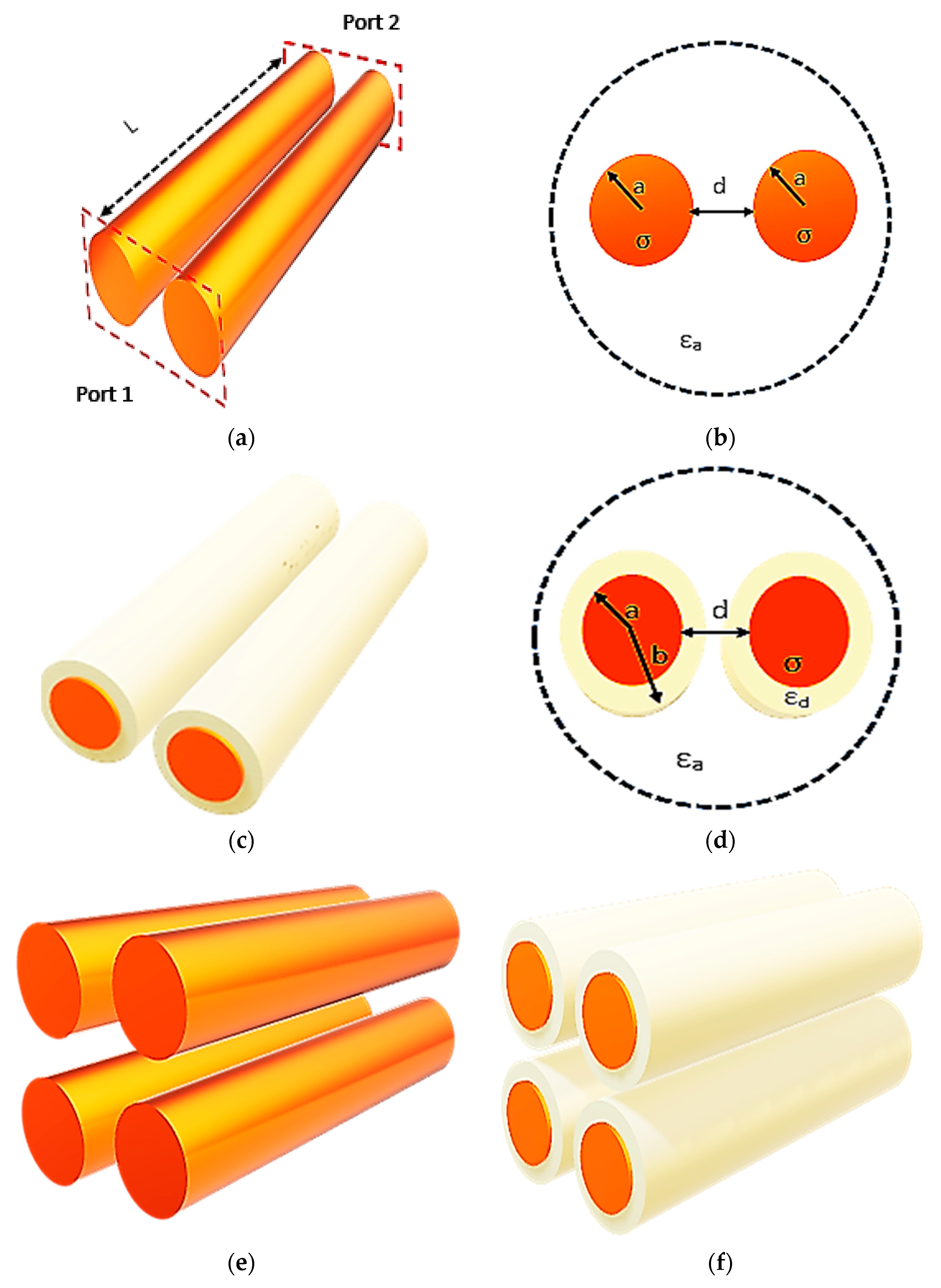
4.1. Two-Wire Waveguide Analysis

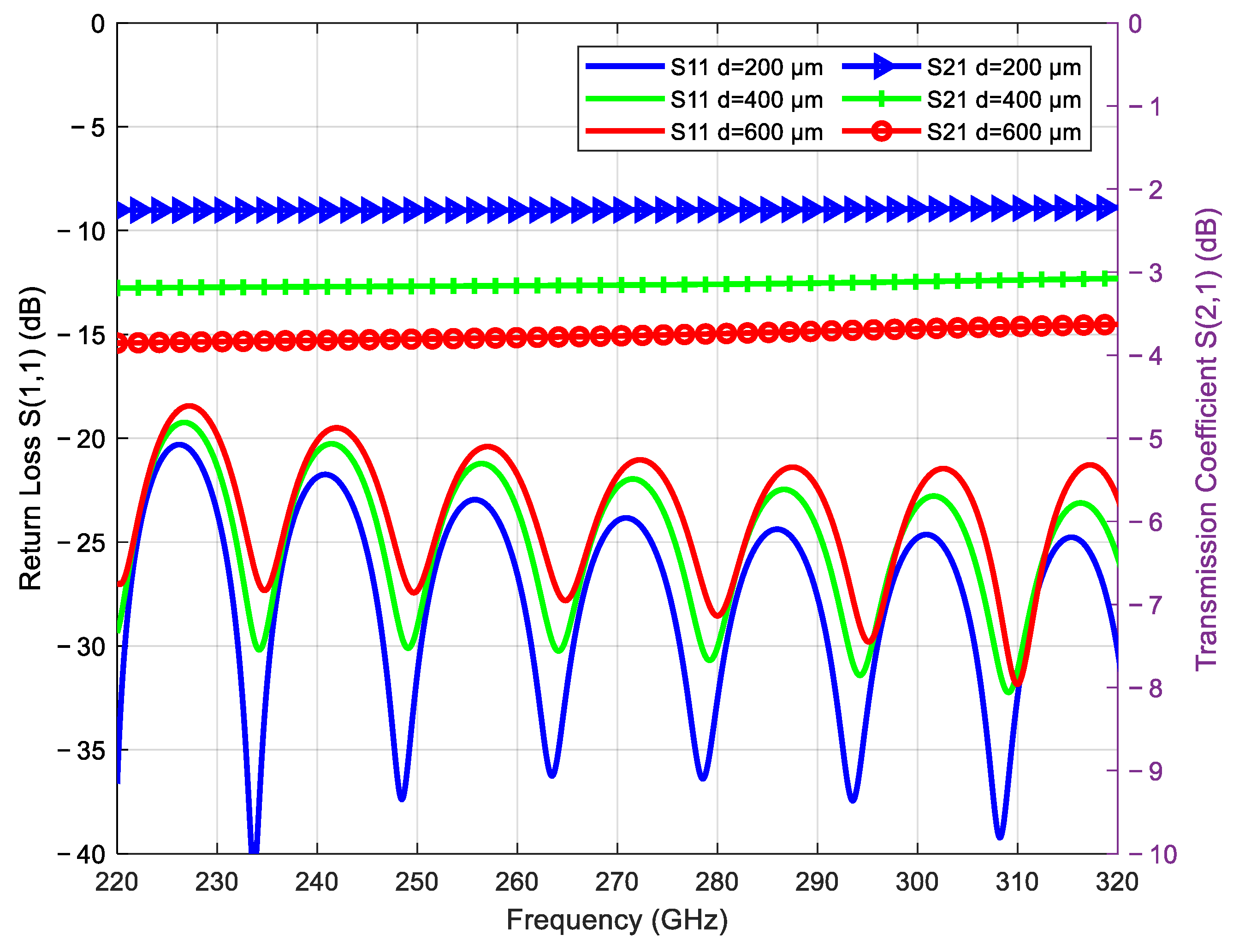
In the design and investigation of transmission lines, return loss and transmission coefficient are essential factors. They are used to determine a transmission line’s performance and assure us that there is no signal loss during transmission. In the initial study, a metallic copper two-wire waveguide for efficient propagation of THz waves was analyzed. Its return loss S(1, 1), as well as transmission coefficient S(2, 1) for three different gaps, 200 µm, 400 µm, and 600 µm, are given in Figure 2.
The return loss for the 200 µm gap was an average of about − 30 dB, while for an increased d of 400 µm and 600 µm, the averages obtained were about −25 dB and −23 dB. The same occurred in the case of the transmission coefficient: narrower gaps had better matching than larger values of 
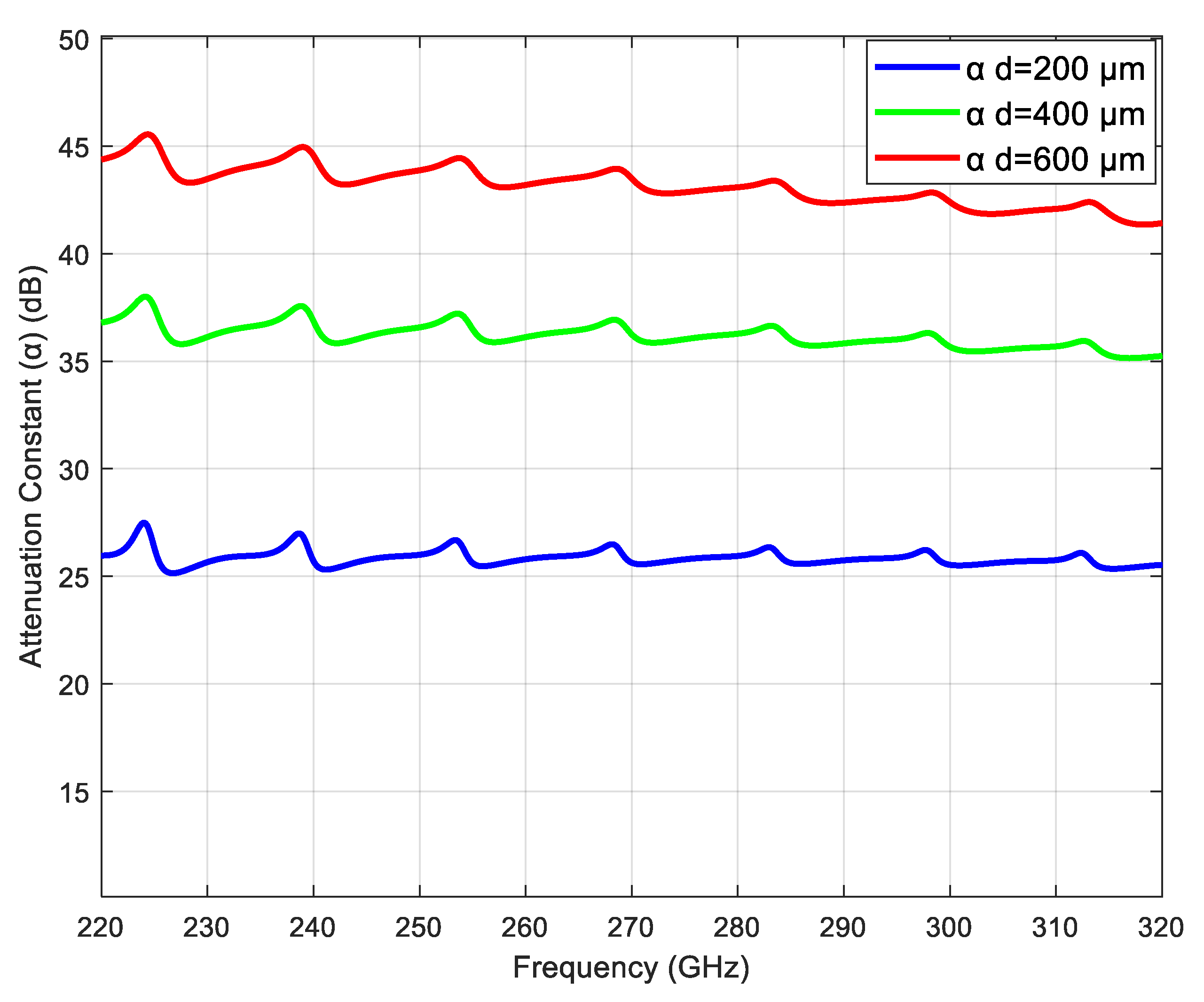
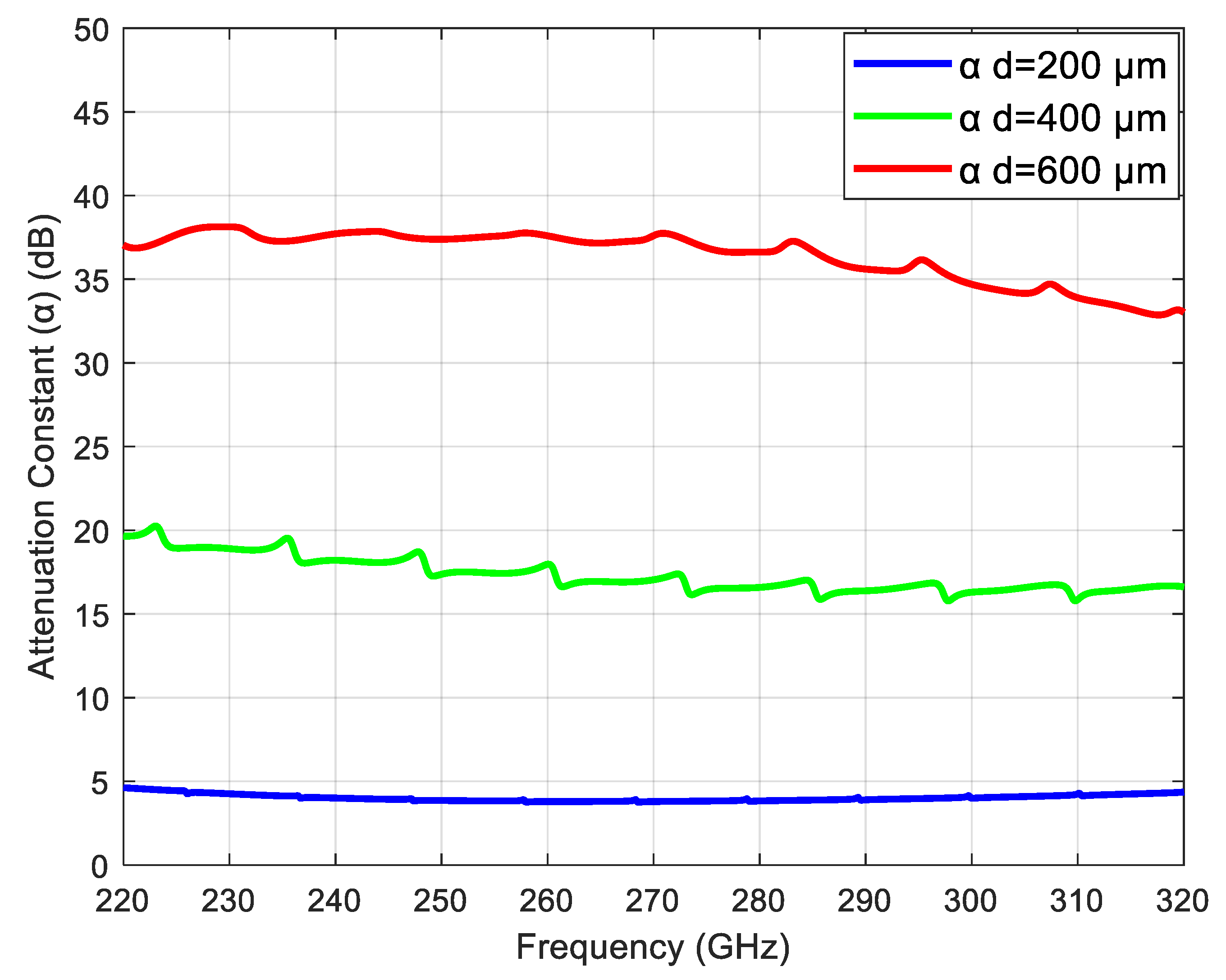
d; the best case was for the wires at 200 µm. This is because the tighter the coupling between the surface waves and the wires, the less power is being reflected to the source, and the more power is transported up the line. Moreover, the frequency and the conductivity of the wires also determine the optimum spacing between two parallel bare copper wires operating in the THz range. It was seen that the spacing between the wires had an impact on the return loss and transmission coefficient for two parallel bare copper wires operating in the THz band. A narrower spacing resulted in a reduced return loss and an improved transmission coefficient. The attenuation constant (α) was a measure of how much the power of a signal decreased as it traveled along a two-wire waveguide, and the attenuation constant for two bare wires for various values of d is shown in Figure 3.
The attenuation constant for 200 µm was about 25 dB/m, while for 400 µm and 600 µm, it was much more of an average, 36 dB/m and 44 dB/m. The signal’s frequency influences the attenuation constant. The attenuation constant of two wires increases with the increase in frequency. This is due to decreased skin depth at higher frequencies, such as the THz range. The electric field between the wires is greater with a smaller gap between them, which improves the efficiency of surface wave propagation. Thus, the signal transmits with less power along the two-wire waveguide as a result. Additionally, the repetitive pattern can be seen in s-parameters and the attenuation constant plot, which is due to the resonance behavior in the proposed wire waveguide, which is not uncommon in waveguide designs. Resonance is a common phenomenon in waveguides, and it may lead to small fluctuations (increases or decreases) in alpha; this shows the complex interaction of two-wire geometry with THz waves.

4.2. Two-Coated-Wire Waveguide Analysis

Despite the bare metal wire waveguide’s low loss and low dispersion advantages, there are some practical implications, such as weakly guided SPP [5,13]. The above-discussed two bare wires were dielectrically coated, and their effect on the s-parameters and the attenuation constant was analyzed. The changes in these parameters due to coating, seen in the percentages for various gap sizes, are shown in Table 2. Rather than showing all the s-parameters and attenuation for two coated wires, only the amount of percentage change is shown for simplification in analysis.
It can be noted that coating has a significant effect on the THz propagation through two wires. The return loss is reduced by about −39% and the transmission coefficient is increased by about 84% for the very small d of 200 µm, a near about double increment. However, it can also be noticed that as the d is increased between the two coated wires, the amount of matching and improvement in the s-parameters increases; S(2, 1) increment of 53% for 400 µm, 16% for 600 µm while there is a S(1, 1) decrement of −12% for 400 µm, and −8% for 600 µm, respectively. Thus, the transmission coefficient and the return loss are improved after coating. This is due to the fact that reflection at the wire waveguide interface is reduced, as the dielectric layer acts as a transition layer between the metal and the surrounding medium. Also, radiation losses are reduced due to the dielectric coating leading to the improvement of s-parameters. Coating the bare wire also influences the propagation characteristics, such as the attenuation constant of the waveguide and the effect of dielectric coating on the attenuation, which can also be seen in Table 2. For the smaller value of d of 200 µm, the reduction in the attenuation is about −84.40% after applying the dielectric coating to the two bare copper wires. However, with the increase in the d between the wires, this downfall rate in the attenuation decreases by −52% and −15% for 400 µm and 600 µm, respectively. Thus, it can be considered that there is a major reduction in the attenuation constant after the application of the dielectric coating, leading to a longer propagation length, as experimentally demonstrated and proved in [28,29].
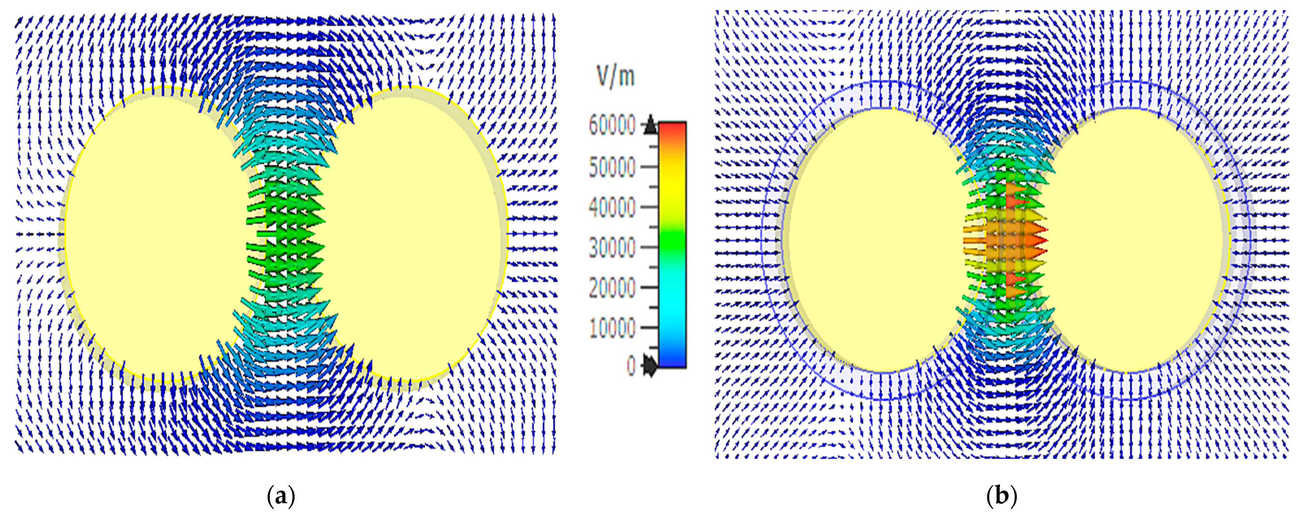
Two coated and uncoated wires were analyzed for the 3D visualization analysis, and the effect of coating on the THz wire waveguide is shown in Figure 4. The maximum electric field intensity of the dielectric coated wires is more than the bare wire; therefore, an average electric field of 6 × 10⁴ was taken for better visualization and analysis.
The electric field strength in the bare wire is spread on one side and between the wires. However, the addition of the dielectric layer between the metallic wires improves the confinement of electric fields inside the waveguide as verified in [17,30]. This improves the coupling between the wires and the effectiveness of energy transfer. Due to the greater energy confinement within the waveguide and the increased electric field, there is a low power loss and better transmission efficiency overall. Power leakage from the waveguide is decreased because of the dielectric coating. The observed increase in the electric field intensity is due to the electric field confinement inside the waveguide, as well as less energy leaking out. That indicates low radiation losses and other losses, which improve signal transmission.
The performance characteristics of the wire waveguide mainly depend on the operating frequency, surface structure, and gap between the wires; therefore, the variation in electric field at different frequencies and gaps is shown in Table 3, with the difference in percentage value after coating the bare wires.
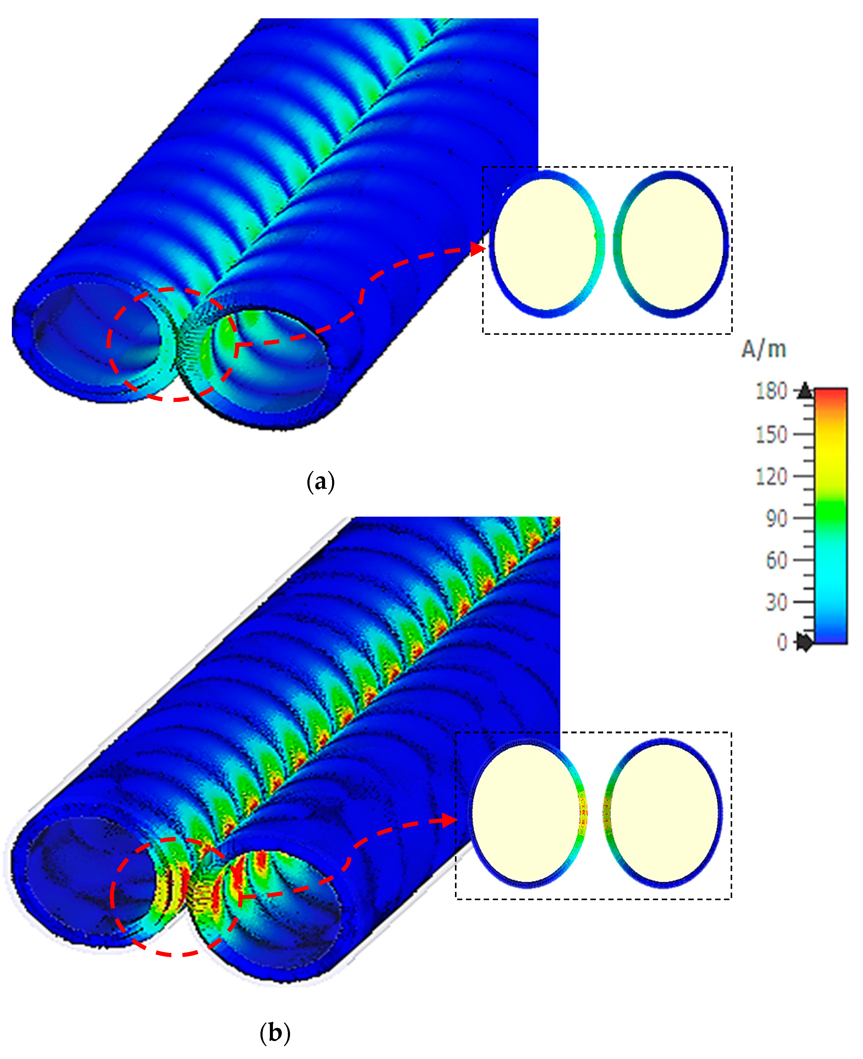
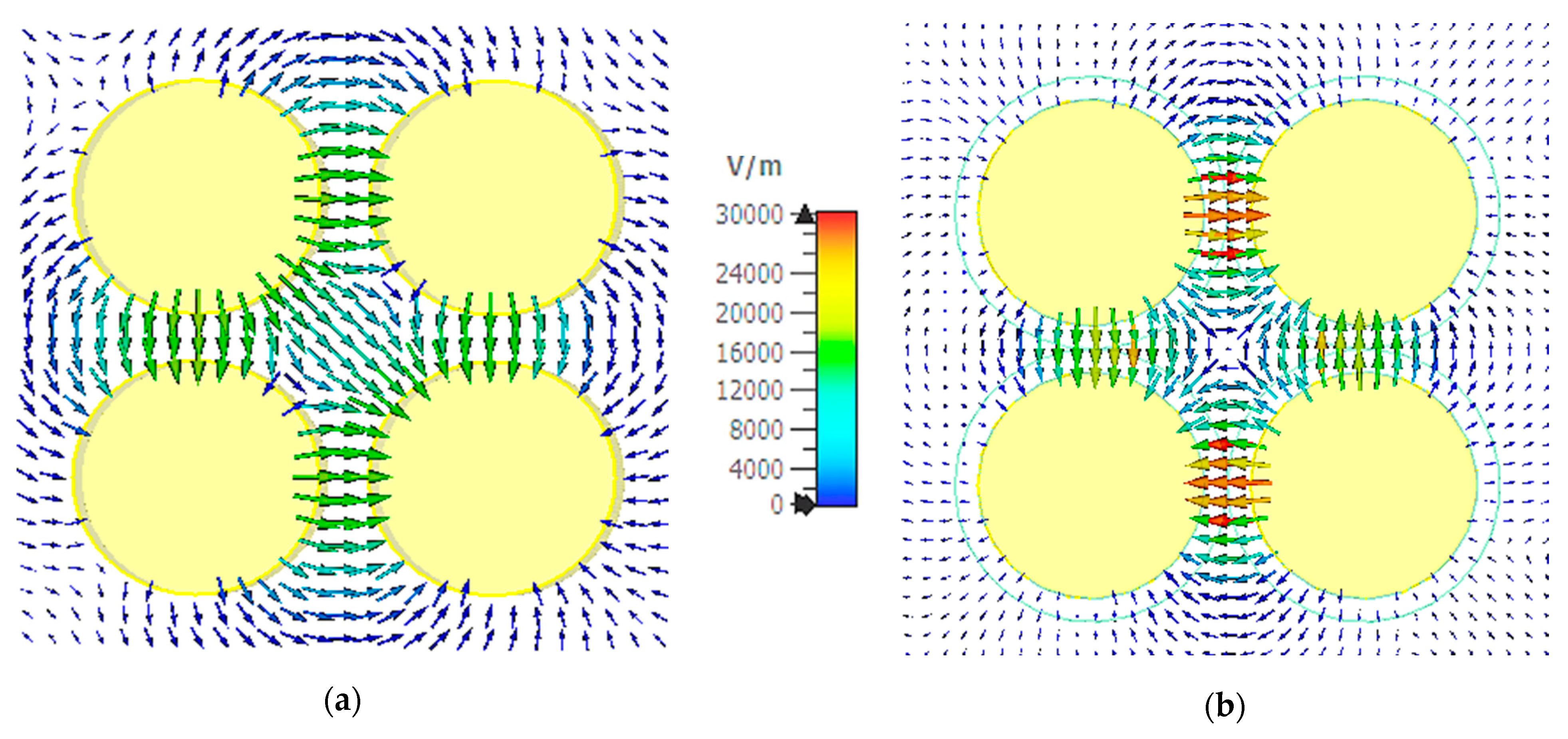
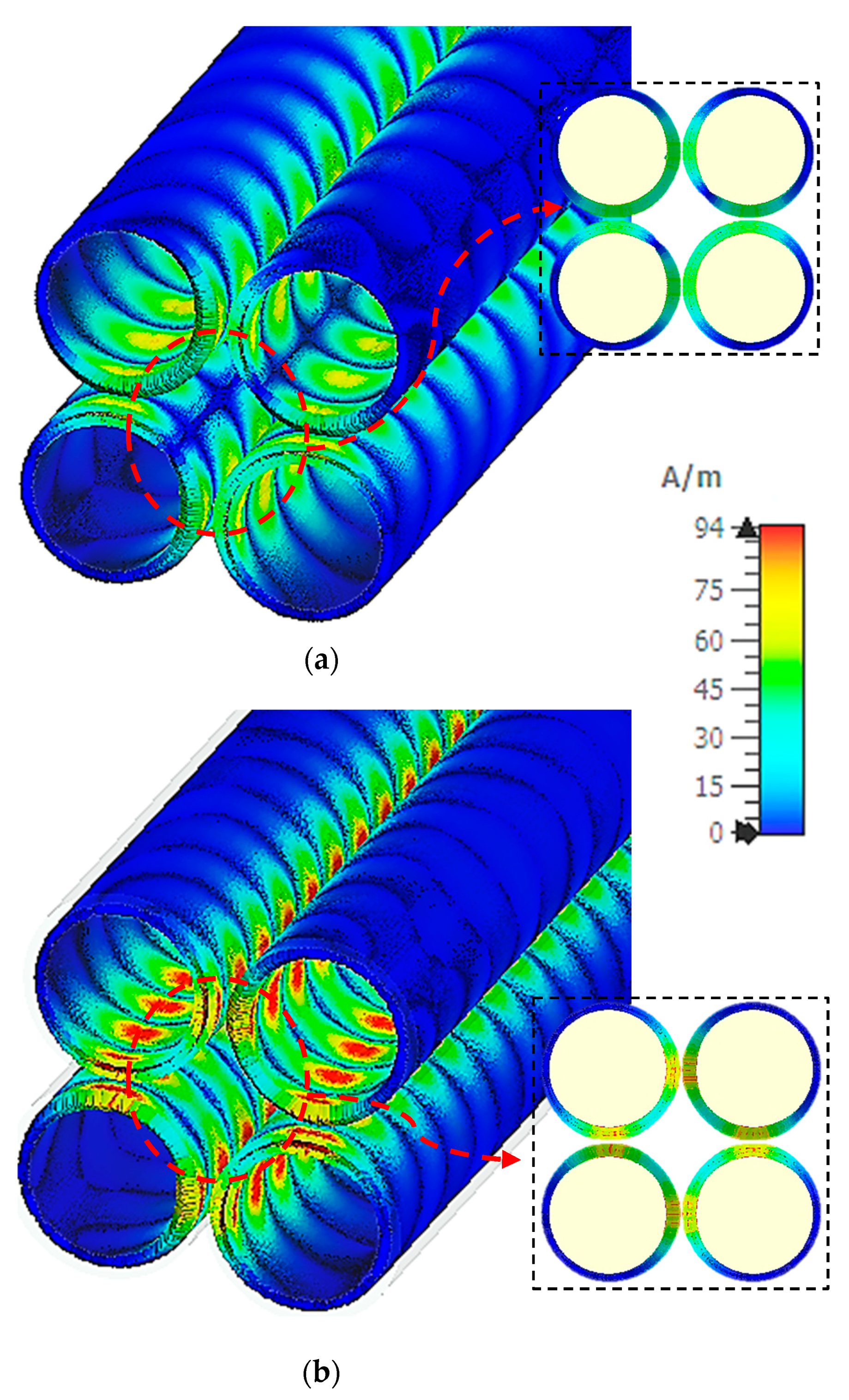
The surface current intensity plot of the two bare and coated wires is shown in Figure 5. This analysis is an important parameter to be analyzed, as it facilitates the researchers identifying the areas with maximum current in a waveguide and identifying any leakage. The maximum surface currents of bare and coated wire waveguides are different due to their geometry; however, the average maximum of both designs selected is 180 A/m for uniform scaling and better visualization of surface current flow and the most intensive areas.
It can be noted in both cases that the maximum current is in between the wires, where the electric field is strongest. After coating the bare wires, the surface current intensity in the dielectric gap between the two wires was increased, as can be seen in Figure 5b. This is due to the fact that dielectric coating increases the effective dielectric constant of the waveguide, which causes the surface current to flow more efficiently, which in turn leads to the high surface current in the waveguide. Also, radiation losses are mitigated due to dielectric coating, leading to better propagation of waves. The electric and magnetic fields in the region between the wires are strongly confined and concentrated, which is clear evidence of a guided mode propagating along the wires. The variation in surface current at different frequencies and d is shown in Table 4.
As can be noticed in Table 4, as the frequency of operation increases, the percentage increment in surface current increases. As the operating frequency is increased, the skin depth is decreased, making the surface more concentrated.
By looking at the analysis of two-wire waveguides for efficient propagation of THz waves, it can be concluded that two bare wires can propagate THz waves efficiently, and when applying the dielectric coating, their performance is significantly improved. Scattering parameters and attenuation constants are much improved after coating. Electric field and surface currents in the two-wire waveguides with and without coating indicate that there is a significant rise in these parameters due to coating, due to the concentration of waves in the region between the wires. Additionally, the d between the two wires and the operating frequency affects the propagation characteristics of THz waves through the two wires.

4.3. Four-Wire Waveguide Analysis

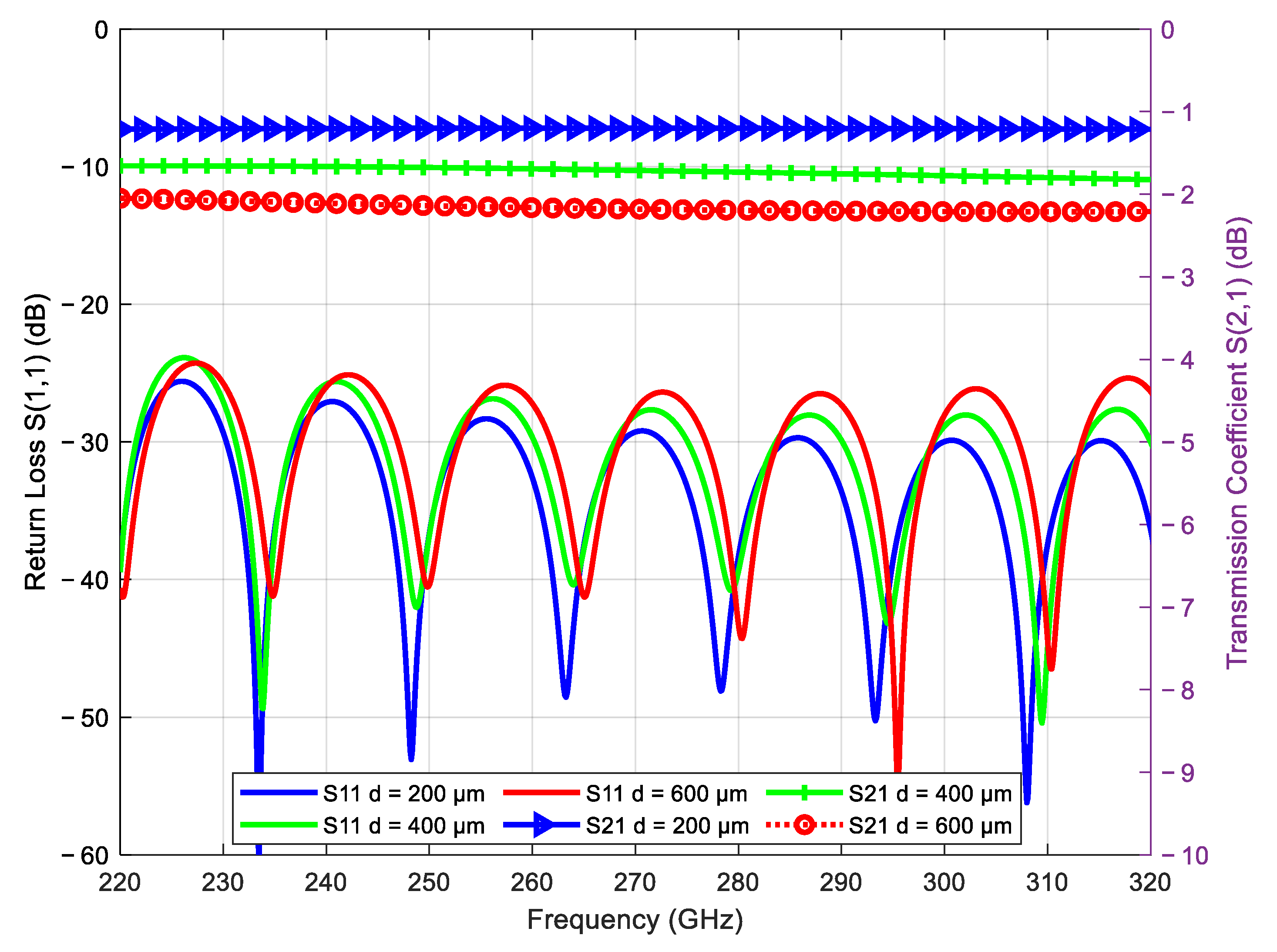
Two-wire waveguides with and without the coating were studied to analyze their feasibility for utilization in next-generation THz transmission systems. Practical and commercially available cables and copper binders consists of more than two wires. Therefore, in this section, the analysis is extended for the four parallel wires with and without coating. For the THz wave transmission through four parallel bare wires, the simulated s-parameters are shown in Figure 6.
The best average return loss achieved was about −34.1 dB with a transmission coefficient of −1.2 dB for d = 200 µm. It can be noticed that, compared to the two bare parallel wires, four-wire waveguides have better transmission coefficients and return loss for all values of d. This is due to the fact that the coupling efficiency of four wires is better than that of the wire waveguide. The main benefit of a four-wire waveguide is that it may support additional propagation modes, which can result in better performance in terms of signal transmission and reflection characteristics, as well as supporting higher-order modes along with the fundamental mode. Similarly, in the case of attenuation constant, four bare wire waveguides have a lower attenuation constant as compared to the two-wire waveguide of the same size and d, as can be seen in Figure 7. The additional wires in the four-wire waveguide as compared to two wires enable more effective confinement of the electric and magnetic fields, resulting in a reduction in energy losses using radiation and leakage. Better transmission efficiency and less attenuation are benefits of this improved confinement. Similarly, as in the case of two wires, four-wire s-parameters and attenuation also experienced periodic picks due to the resonance effect.

4.4. Coated Four-Wire Waveguide Analysis

Usually, in the infrastructure, already installed wires are coated for several advantages, such as radiation leakage prevention, environmental protection, etc. For the realization of TDSL and the utilization of coated wires for their efficient propagation, its analysis is important.
The four bare wires discussed above were dielectrically coated, and their effects on the s-parameters and the attenuation constant were analyzed. The percentage change in these parameters at various values of d due to coating is shown as percentages in Table 5.
As the d between the wires increased, the effect or the change in the percentage of s-parameters and attenuation constant decreased. As for d = 200 µm, the percentage change was 76% for attenuation as well as transmission coefficient, but for the gap of 600 µm, the percentage change was reduced to only 10%. The return loss was also decreased after coating, −30% in the case of d = 200 µm, and the percentage change was reduced with an increment in d. It can again be validated after two-wire coating analyses that in the four-wire analysis, after coating the bare wires, there was a significant improvement in the s-parameters and the attenuation constant of the THz wire waveguide.
Electric field and surface current at the THz frequency range were investigated in a four-wire waveguide with and without coating. Figure 8 shows a 3D representation of the four-wire waveguide’s bare and dielectrically coated electric field distribution pattern.
For better visualization and analysis, the average electric field was set at 3 × 10⁴ V/m. It can be seen in the 3D analysis of the electric field distribution that for the gap of 200 µm, dielectrically coating the bare wire increased the electric field intensity, thus improving the field confinement. The maximum electric field intensity can be seen in the red area, and the concentration is in the inner portion between the wires, showing that the THz waves are propagating through the surface and dielectric gap between the wires.
The performance of the waveguide is mainly affected by the operating frequency, as in the THz range, waves are too short that it approaches to the size of gap between wires and dielectric coating thickness. So, it is important to analyze the four-wire waveguide at the lowest, center, and highest frequencies of the proposed band for better analysis. For various d and center frequencies, changes were observed in the electric field of the four-wire waveguides with and without dielectric coating. Therefore, for simplification, only the percentage differences in the electric field for different gaps and three different frequencies are summarized in Table 6.
The above percentage difference table clearly shows the rise and fall in the electric field due to d and frequency. For the gap sizes of 200 µm and 400 µm, there was an increase in electric field. This is because the effective dielectric constant of the waveguide was increased as a result of the dielectric coating. Since surface waves propagate more effectively due to the higher dielectric constant, the electric field between the wires obtained was stronger as a result. Also, the dielectric layer reduced the radiation losses, thus confining the electric field to the waveguide. Moreover, when the d between the wires was increased further to 600 µm, there was a downfall of the electric field, as the d is large and the electric field force is weak. Figure 9 shows the surface current for the center frequency of 270 GHz and a d of 200 µm.
The same phenomenon as in the case of two wires with and without coating occurred in four wires with and without coating; the maximum surface current was in the gap between the wires, as can be seen in both cases of four wires (Figure 9a,b). However, the concentration value is greater in the case of dielectric coating. This parameter is also affected by the frequency propagating; therefore, only the percentage differences in the surface current for different d and three different frequencies, i.e., 220, 270, and 320 GHz, are summarized in Table 7.

5. Highlights in Achievement of Two- and Four-Wire Waveguides

Propagation of THz waves through two wires has been studied and proved as an efficient waveguide for future communication systems such as TDSL, as discussed in Section 1. It is feasible to draw strong conclusions by looking at the significant research done on two-wire and four-wire waveguides for effective THz wave propagation. The ability of these bare wires to effectively transmit THz waves demonstrates their potential as feasible waveguides for THz communication and sensing applications. However, the addition of a dielectric coating significantly enhances the waveguide’s performance. The analyses of the attenuation constants and scattering characteristics are much improved with the dielectric coating.
The s-parameters and attenuation constant analyses that were studied above showed that coating the bare metallic wires improved the propagation characteristics of two- and four-wire waveguides. Due to several limitations, such as the availability of computational resources, a 20 mm wire waveguide was studied in this work. Therefore, an estimation for losses per unit length can be calculated by dividing the length of wire with the attenuation constant value. However, in future, upon availability of resources, an analysis of a longer waveguide with detailed effects will be studied. Table 8 shows the average of these parameters for the optimum d, which is 200 µm at a center frequency of 270 GHz.
It can be seen in the surface current analysis that with coating, the surface current in the waveguide is increased in both the two-wire and four-wire cases. Surface current is the source of surface plasmonic polariton, and it is the reason that the electromagnetic field that propagates through the dielectric and metallic interface is created. SPPs are sustained by the localized EM field created by the surface current. Therefore, the higher the surface current created, the stronger the localized fields that enhance the propagation of SPPs. Similarly, a high electric field between the two and four wires produces stronger oscillations of electrons in the metal, leading to higher surface currents. However, the thickness of dielectric material, material dielectric constant, frequency, gap, and other related parameters decide the optimum choice for efficient THz wire waveguides for future communication systems.

6. Conclusions

The behavior and performance of THz waveguides with metallic wires, whether bare or coated with dielectric material, have undergone extensive study for high-frequency applications, specifically sub-THz. Numerous key insights have been gleaned from electromagnetic simulations and research. Notably, the application of a dielectric coating to metallic wires significantly enhances the waveguide’s performance. This coating diminishes power leakage and radiation losses by augmenting energy confinement within the waveguide. These findings underscore the importance of investigating surface currents and analyzing electric fields to enhance waveguide performance. Moreover, they demonstrate the potential of dielectric-coated metallic wire waveguides for efficient THz propagation. The research provides valuable design recommendations for enhancing THz waveguide performance using dielectric coatings. Further exploration of specific dielectric materials, coating thicknesses, and frequency ranges could facilitate additional optimization and adaptation of waveguide designs for various THz applications.

Author Contributions

Conceptualization, F.C.S. and A.J.A.A.-G.; Methodology, A.A.S.; Software, N.S.B.I.; Validation, F.C.S.; Formal analysis, H.A.; Resources, M.A.; Data curation, Y.S.K. and M.A.; Writing – original draft, A.A.S. and A.J.A.A.-G.; Visualization, T.A.H.A.; Project administration, A.J.A.A.-G.; Funding acquisition, T.A.H.A. All authors have read and agreed to the published version of the manuscript.

Funding

This research was supported by Researchers Supporting Project number (RSPD2023R868), King Saud University, Riyadh, Saudi Arabia.

Institutional Review Board Statement

Not applicable.

Informed Consent Statement

Not applicable.

Data Availability Statement

Not applicable.

Acknowledgments

The authors would like to acknowledge the support provided by Researchers Supporting Project number (RSPD2023R868) at King Saud University, Riyadh, Saudi Arabia. This research was also supported by the Ministry of Higher Education Malaysia (MOHE) through the Fundamental Research Grant Scheme, FRGS/1/2020/TK0/UTHM/03/17, and the Research Management Center (RMC) through the TIER Grant (Q379) at Universiti Tun Hussein Onn Malaysia (UTHM). Furthermore, the authors extend their appreciation to Universiti Teknikal Malaysia Melaka (UTeM).

Conflicts of Interest

The authors declare no conflict of interest.

References

  1. Lee, Y.S. Principles of Terahertz Science and Technology; Springer Science & Business Media: Berlin, Germany, 2009; Volume 170. [Google Scholar] [CrossRef]
  2. US Federal Communications Commission. FCC Opens Spectrum Horizons for New Services & Technologies; US Federal Communications Commission: Washington, DC, USA, 2019. [Google Scholar]
  3. Horwitz, J. FCC Opens 95GHz to 3THz Spectrum for 6G, 7G, or Whatever Is Next. Venture Beat 15 March 2019.
  4. Hillger, P.; Grzyb, J.; Jain, R.; Pfeiffer, U.R. Terahertz imaging and sensing applications with silicon-based technologies. IEEE Trans. Terahertz Sci. Technol. 2018, 9, 1–19. [Google Scholar] [CrossRef]
  5. Cioffi, J.M.; Kerpez, K.J.; Hwang, C.S.; Kanellakopoulos, I. Terabit DSLs. IEEE Commun. Mag. 2018, 56, 152–159. [Google Scholar]
  6. Souza, D.D.; Sousa, B.P.T.; Borges, G.S.; Rodrigues, R.M.; Cavalcante, A.M.; Almeida, I.M.; Costa, J.C.W.A. Evaluation of Copper Cables as Waveguides in Next-generation Wireline Technologies. In Proceedings of the SBMO/IEEE MTT-S International Microwave and Optoelectronics Conference, IMOC 2019, Aveiro, Portugal, 10–14 November 2019; Institute of Electrical and Electronics Engineers Inc.: Piscataway, NJ, USA, 2019. [Google Scholar] [CrossRef]
  7. Ahmed, A.; Seman, F.B.C.; Khee, Y.S.; Ahmed, I. Study on Circular Waveguide for CAT6e Cable for Future Communication Systems. In Proceedings of the 2022 IEEE MTT-S International Microwave Workshop Series on Advanced Materials and Processes for RF and THz Applications (IMWS-AMP), Guangzhou, China, 27–29 November 2022; pp. 1–3. [Google Scholar] [CrossRef]
  8. Syahnon, M.S.; Malaysia, U.T.H.O.; Yee, S.K.; Seman, F.C.; Ahmad, A. Investigation of Waveguide Propagation of Terahertz Signal with Different Polarization Angle and Twisting Rate for Terabit DSL Application. J. Electron. Volt. Appl. 2022, 3, 67–71. [Google Scholar]
  9. Yan, L.K.; Malaysia, U.T.H.O.; Seman, F.C.; Khee, Y.S.; Sohoo, A.A. Propagation Characteristics in a Circular Waveguide for Feasibility Study of Terabit DSL. J. Electron. Volt. Appl. 2022, 3, 41–46. [Google Scholar] [CrossRef]
  10. Dong, J.; Tomasino, A.; Balistreri, G.; You, P.; Vorobiov, A.; Charette, É.; Le Drogoff, B.; Chaker, M.; Yurtsever, A.; Stivala, S.; et al. Versatile metal-wire waveguides for broadband terahertz signal processing and multiplexing. Nat. Commun. 2022, 13, 741. [Google Scholar] [CrossRef]
  11. Wang, K.; Mittleman, D.M. Metal wires for terahertz wave guiding. Nature 2004, 432, 376–379. [Google Scholar] [CrossRef]
  12. Berenguer, A.; Baquero-Escudero, M.; Sanchez-Escuderos, D.; Ferrando-Bataller, M. Reduction of radiation losses of the single-wire waveguide at THz frequencies. In Proceedings of the 2013 USNC-URSI Radio Science Meeting (Joint with AP-S Symposium), Lake Buena Vista, FL, USA, 7–13 July 2013; p. 170. [Google Scholar] [CrossRef]
  13. Astley, V.; Scheiman, J.; Mendis, R.; Mittleman, D.M. Bending and coupling losses in terahertz wire waveguides. Opt Lett Opt. Lett. 2010, 35, 553–555. [Google Scholar] [CrossRef]
  14. Cao, H.; Nahata, A. Coupling of terahertz pulses onto a single metal wire waveguide using milled grooves. Opt. Express 2005, 13, 7028–7034. [Google Scholar] [CrossRef]
  15. Bashirpour, M.; Ghorbani, S.; Kolahdouz, M.; Neshat, M.; Hajhosseini, H.; Mansouree, M.; Fathipour, M. Simulation and Fabrication of Photoconductive Antenna on LTG-GaAs for Terahertz Radiation. In Proceedings of the Asia Communications and Photonics Conference 2016, Wuhan China, 2–5 November 2016. [Google Scholar] [CrossRef]
  16. Mbonye, M.; Mendis, R.; Mittleman, D.M. A terahertz two-wire waveguide with low bending loss. Appl. Phys. Lett. 2009, 95, 233506. [Google Scholar] [CrossRef]
  17. Pahlevaninezhad, H.; Darcie, T.E.; Heshmat, B. Two-wire waveguide for terahertz. Opt. Express 2010, 18, 7415–7420. [Google Scholar] [CrossRef]
  18. Mridha, M.K.; Mazhorova, A.; Clerici, M.; Al-Naib, I.; Daneau, M.; Ropagnol, X.; Peccianti, M.; Reimer, C.; Ferrera, M.; Razzari, L.; et al. Active terahertz two-wire waveguides. Opt. Express 2014, 22, 22340–22348. [Google Scholar] [CrossRef]
  19. Sohoo, A.; Seman, F.C.; Sohu, I.A.; Hazirah, N.U.; Chandio, A.F. Investigation of Two-Wire Power Line for Efficient Propagation of THz Waves for Future 6G Communication Systems. J. Appl. Eng. Technol. (JAET) 2023, 7, 48–56. [Google Scholar] [CrossRef]
  20. Shrestha, R.; Kerpez, K.; Hwang, C.S.; Mohseni, M.; Cioffi, J.M.; Mittleman, D.M. A wire waveguide channel for terabit-per-second links. Appl. Phys. Lett. 2020, 116, 131102. [Google Scholar] [CrossRef]
  21. Goubau, G. Surface Waves and Their Application to Transmission Lines. J. Appl. Phys. 1950, 21, 1119–1128. [Google Scholar] [CrossRef]
  22. Zelby, L.W. Propagation modes on a dielectric coated wire. J. Frankl. Inst. 1962, 274, 85–97. [Google Scholar] [CrossRef]
  23. Berenguer, A.; Baquero-Escudero, M.; Sanchez-Escuderos, D.; Ferrando-Bataller, M. Reduction of high-order modes coupling on bends in the dielectric-coated single wire waveguide. In Proceedings of the 6th European Conference on Antennas and Propagation, EuCAP 2012, Prague, Czech Republic, 26–30 March 2012; pp. 990–994. [Google Scholar] [CrossRef]
  24. CST Studio Suite Team. CST Microwave Studio 2010—Workflow and Solver Overview; CST GmbH: Ilsenburg, Germany, 2010. [Google Scholar]
  25. Lai, C.H.; Hsueh, Y.C.; Chen, H.W.; Huang, Y.J.; Chang, H.C.; Sun, C.K. Low-index terahertz pipe waveguides. Opt. Lett. 2009, 34, 3457–3459. [Google Scholar]
  26. Molnar, D.; Schaich, T.; Al-Rawi, A.; Payne, M. Interaction between surface waves on wire lines. Proc. R. Soc. A Math. Phys. Eng. Sci. 2021, 477, 20200795. [Google Scholar] [CrossRef]
  27. Orfanidis, S.J.; Ramaccia, D.; Toscano, A. Electromagnetic Waves and Antennas Exercise Book. 2002. Available online: www.ece.rutgers.edu/~orfanidi/ewa (accessed on 24 October 2023).
  28. Gerasimov, V.V.; Knyazev, B.A.; Lemzyakov, A.G.; Nikitin, A.K.; Zhizhin, G.N. Growth of terahertz surface plasmon propagation length due to thin-layer dielectric coating. J. Opt. Soc. Am. B 2016, 33, 2196–2203. [Google Scholar] [CrossRef]
  29. Petrov, N.I. Propagation of Terahertz Surface Plasmon Polaritons in a Dielectric Fiber with a Metal Wire Core. Fibers 2022, 10, 89. [Google Scholar] [CrossRef]
  30. Sousa, B.; Souza, D.D.; Borges, G.; Rodrigues, R.; Cavalcante, A.; Costa, J. Coupling Impact Between a Radial Antenna and Guided Modes on Twisted-Pair Systems Operating in Millimeter-Wave. J. Commun. Inf. Syst. 2021, 36, 75–84. [Google Scholar] [CrossRef]
Figure 1. Wire waveguide with and without coating. (a) Two Bare Wires. (b) Wire Cross sectional View showing Material Properties. (c) Two Coated Wires. (d) Coated Wire Cross Sectional View showing Material Properties. (e) Four Bare Wires. (f) Four Coated Wires.
Coatings 13 01857 g001
Figure 2. S-parameters for two bare wires at various values of d.
Coatings 13 01857 g002
Figure 3. Attenuation constant for two bare wires for various values of d.
Coatings 13 01857 g003
Figure 4. Electric field strength in two-wire waveguide. (a) Bare two wires. (b) Coated two wires.
Coatings 13 01857 g004
Figure 5. Surface current in two wires with and without coating. (a) Two bare wires. (b) Two coated wires.
Coatings 13 01857 g005
Figure 6. S-parameters for the four bare wires for various values of d.
Coatings 13 01857 g006
Figure 7. Attenuation constant for four bare wires for various values of d.
Coatings 13 01857 g007
Figure 8. Electric field strength in four bare and coated waveguides. (a) Bare wire e. field. (b) Coated wire e. field.
Coatings 13 01857 g008
Figure 9. Surface current for four wires, with and without coating. (a) Four bare wire surface current. (b) Four coated wire surface current.
Coatings 13 01857 g009
Table 1. Simulation parameters followed in this study.
Wire TypeSimulation TimeStep SizeCells per WavelengthMesh SizeBoundary ConditionsBackground Model
2 bare wires≈1700 s100 MHz201,435,392Open (x, y, z)VacuumFEM
2 coated wires≈2930 s100 MHz202,356,016Open (x, y, z)VacuumFEM
4 bare wires≈3182 s100 MHz202,661,456Open (x, y, z)VacuumFEM
4 coated wires≈5280 s100 MHz204,400,952Open (x, y, z)VacuumFEM
Table 2. Percentage change in s-parameters and attenuation constant in two wires after coating.
Parameterd = 200 µmd = 400 µmd = 600 µm
Difference (%)S(1, 1)−39%−12%−8%
S(2, 1)84%53%16%
α−84.40%−52.20%−15%
Table 3. Percentage change in electric field after coating.
Frequencyd = 200 µmd = 400 µmd = 600 µm
Difference (%)220 GHz4.6%13.3%3.8%
270 GHz2.2%14.6%6.5%
320 GHz3.6%12.5%1.2%
Table 4. Percentage change in surface current after coating.
Frequencyd = 200 µmd = 400 µmd = 600 µm
Difference (%)220 GHz37.4%20.6%25.0%
270 GHz39.9%41.8%34.9%
320 GHz44.7%23.7%45.9%
Table 5. Percentage change in s-parameters and attenuation constant in four wires after coating.
Parameterd = 200 µmd = 400 µmd = 600 µm
Difference (%)S(1, 1)−30%−5%−1%
S(2, 1)76%65%10%
α−76%−64%−10%
Table 6. The difference in the electric field for four wires, with and without coating.
Frequencyd = 200 µmd = 400 µmd = 600 µm
Difference (%)220 GHz8.2%3.2%−17.2%
270 GHz4.7%2.5%−9.7%
320 GHz6.3%0.2%−17.2%
Table 7. The difference in surface current in four wires, with and without coating.
Frequencyd = 200 µmd = 400 µmd = 600 µm
Difference (%)220 GHz33.1%13.0%3.8%
270 GHz37.8%18.2%15.8%
320 GHz44.8%25.4%25.8%
Table 8. Average values of propagation constant at d = 200 µm.
Two-WireFour-Wire
BareCoatedBareCoated
S11−2.2 dB−38.9 dB−34.1 dB−44 dB
S21−2.2−0.34 dB−1.2 dB−0.2 dB
Alpha25.8 dB4.02 dB13.8 dB3.3 dB
Electric Field (V/m)60,947 62,30129,57130,954
Surface Current (A/m)15822179.1109
Disclaimer/Publisher’s Note: The statements, opinions and data contained in all publications are solely those of the individual author(s) and contributor(s) and not of MDPI and/or the editor(s). MDPI and/or the editor(s) disclaim responsibility for any injury to people or property resulting from any ideas, methods, instructions or products referred to in the content.

