Article

Features of Electron Beam Processing of Mn-Zn Ferrites in the Fore-Vacuum Pressure Range in Continuous and Pulse Modes

Laboratory of Plasma Electronics, Tomsk State University of Control Systems and Radioelectronics, 634050 Tomsk, Russia
*
Author to whom correspondence should be addressed.
Coatings 2023, 13(10), 1766; https://doi.org/10.3390/coatings13101766
Submission received: 14 September 2023 / Revised: 7 October 2023 / Accepted: 8 October 2023 / Published: 13 October 2023

Abstract

:
The results of electron beam processing of Mn-Zn ferrite samples using pulsed and continuous electron beams in the fore-vacuum pressure range (10 Pa) are presented. We find that continuous electron beam processing leads to surface structuring of the ferrite, changes in elemental composition on the surface, and electrical property modification. The degree of ferrite parameter changes exhibits a threshold behavior. For surface processing temperatures below 900 °C, changes are barely noticeable, while for temperatures over 1100 °C the surface resistance decreases by more than an order of magnitude to values of less than 3 kOhm. Electron beam processing with millisecond pulse duration and pulse energy density exceeding 15 J/cm2 results in the formation of low zinc content melt islands, while the remaining surface area (outside the islands) elemental content and ferrite properties remain largely unchanged. The thickness of the modified layer depends on the processing mode and can be controlled over the range of 0.1–0.5 mm. Due to its low resistance, the modified layer can be utilized to enhance the RF-absorbing properties of the ferrite, which is important in the design of modern magnetic elements of electronic equipment.

1. Introduction

Mn-Zn ferrites have a wide range of applications due to their combination of low cost and unique properties, including high magnetic permeability, resistivity, dielectric permittivity, temporal and temperature stability, and more [1,2]. Mn-Zn ferrites are categorized as soft magnetic materials and possess low coercive force, enabling the easy modulation of their magnetization [3]. These materials are used in the production of magnetic cores, transformer cores, high-frequency inductor coils, and as components in microwave devices [4,5,6,7,8], where frequency requirements are below 2 GHz.
The properties of Mn-Zn ferrites significantly depend on the synthesis method [9,10,11], composition and quantity of doping impurities [12,13,14,15,16], and post-surface treatment method [17,18]. Progress in materials science has led to the development of various ferrite synthesis methods, differing in the source materials, duration, energy efficiency, morphological, and magnetic properties of the ferrites produced. The most widespread methods of ferrite synthesis include sol–gel [19,20,21,22], traditional ceramic fabrication [23,24], solid-phase reaction [25,26], self-combustion [27,28], laser deposition [29,30,31], radiation–thermal sintering [32,33,34], and others. Ferrite synthesis techniques are continually improving through the introduction of new additives [35], optimization of sintering temperature regimes [36,37,38], and the combination of soft and hard magnetic ferrites [39].
In contrast to improving ferrite properties through various sintering methods, energy flux treatment of finished products allows for a controlled modification of their surface properties (electrical conductivity, wear resistance, etc.) and microstructure, with minimal impact on the internal structure. Regions with enhanced electrical conductivity and developed microstructure formed on the surface greatly influence the RF-absorbing and -scattering properties of ferrites [40]. The development of methods for modifying the structure of ferrite products has become an important task when designing modern magnetic elements of electronic equipment.
The structural modification of ferrites involves thermal treatment, laser-induced etching [41,42], electron beam irradiation [43,44,45,46], and ion beam irradiation [47,48]. Etching in a gaseous environment using laser irradiation allows for the formation of sharp-edged grooves for use in magnetic heads. The dimensions of etched areas are on the order of tens of micrometers, limiting the applicability of this method for changing properties over a large surface area. Gamma irradiation of the surface of Mn1Zn0.3Fe2O4 ferrite nanoparticles, as reported in [49], results in changes in cation distribution proportional to the gamma radiation dose. Reduction in lattice constant, physical particle size, and increase in saturation magnetization were observed, which could be beneficial for medical applications such as targeted drug delivery, gene therapy, hyperthermia, and MRI thermometry. The high-energy irradiation of bulk ferrite results in morphological changes and structural-phase transitions, negatively affecting the preservation of the structure and properties of these materials [50]. Irradiation with high-energy ions leads to the formation of a “dead” layer, thereby affecting the ferrite magnetic properties.
One of the emerging methods for modifying the structure of ferrite products is electron beam treatment using low-energy electron beams in the fore-vacuum pressure range (pressure of order 1–100 Pa) [51]. Electron beam propagation at these pressures creates a “beam-plasma”, the positive ions from which effectively neutralize the negative charge brought by the electron beam to the irradiated non-conducting surface [52]. Additionally, higher working pressures compared to pressures customarily used in high-energy electron beam treatment with electron energies of several hundred keV allow for controlling the stoichiometric composition of ferrites during irradiation through working in an oxygen environment. A promising method for ferrite surface modification by electron beams could be pulsing the treatment, thereby attaining higher specific beam power than in continuous mode. Previous studies have shown that treatment of the surface of Mn-Zn ferrite with low-energy electrons leads to surface recrystallization of the original ferrite, forming prismatic hematite Fe2O3 crystals [53]. Here, we describe our investigation into the influence of electron beam treatment in continuous and pulse modes on the structural and electro-physical properties of Mn-Zn ferrites.

2. Materials and Methods

Ferrite rings with a diameter 16 mm and a thickness 5 mm, designated as 2000 NM, were used as the material for the study. The chemical composition of the ferrite is Mn0.6Zn0.4Fe3O3. The selection of this material was based on its high initial relative magnetic permeability and its significant absorption capacity in the high-frequency electromagnetic range. The principal electro-physical parameters of the material are shown in Table 1.
The investigation of the structure, elemental composition, and the surface of substrates after electron beam treatment was performed using a Hitachi S-3400N scanning electron microscope (Hitachi Science & Technology, Tokyo, Japan) equipped with a Bruker XFlash 5010 energy-dispersive X-ray analysis attachment (Bruker AXS Microanalysis, Karlsruhe, Germany).
An SEM image and the elemental composition of the surface of the non-irradiated ferrite are shown in Figure 1 and Table 2, respectively.
As is evident from the image, the unprocessed surface of the 2000 NM ferrite exhibits a homogeneous structure composed of grains of non-uniform size. The SEM image also indicates that the sample possesses relatively good microstructure with low porosity. The energy-dispersive X-ray analysis data of mass and atomic percentages of elements (Table 2) demonstrates that the elemental composition is closely aligned with the stoichiometric values.

3. Methodology of Electron Beam Processing of Ferrites

3.1. Continuous Mode Processing

Electron beam processing in the continuous mode was conducted using a low-energy electron beam with energy ranging from 2 to 10 keV and beam power from 50 to 400 W, on an experimental setup in an oxygen atmosphere at a pressure of 10 Pa. A focused electron beam was generated by a fore-vacuum-pressure plasma-cathode electron source based on a hollow cathode glow discharge [54]. A schematic representation of the experimental setup is shown in Figure 2.
A fore-vacuum plasma electron source was installed on the upper flange of the vacuum chamber. The main components of the source include a cylindrical hollow cathode, a flat anode, and a conically shaped extractor. When applying a voltage Ud between the cathode and anode, a glow discharge with current Id up to 1 A is ignited. Electron emission occurs through an emission window in the anode, which consists of a tantalum plate of thickness 1 mm with an emission aperture of diameter 0.7 mm. Beam-accelerating voltage Ua is supplied from a Spellman SR6 high-voltage source and is set in the range of 2–10 kV. The specialized design of the source accelerating section allows for the formation of a continuous electron beam with current Ie up to 100 mA at a pressure of 10 Pa in both the source and vacuum chamber. The beam is focused magnetically and can be controlled by adjusting the focusing coil current.
The ferrite rings to be irradiated are positioned on individual holders, which are steel cylinders with raised edges to secure the ferrites. To reduce thermal loss through conduction, the holders are placed on 10 cm long and 4 mm diameter spikes. Holders for five samples are set on a translation device, enabling sequential positioning of each ferrite in the region exposed to electron beam treatment. A single loading in the vacuum chamber thus allows for the treatment of up to five ferrite samples. The beam power density in the treatment area ranged from 200 to 850 W/cm2, adjusted by modifying the beam current and diameter. The treatment process utilizes a tightly focused electron beam with diameter up to 1 mm that is raster-scanned over a square scan area, with each side exceeding the diameter of the treated ferrite by 1–2 mm; uniformity of treatment is thus achieved.
The temperature of the ferrite surface during beam irradiation was measured using a RAYTEK 1MH infrared pyrometer (Raytek Corp., Santa Cruz, CA, USA) with measuring range of 550–3000 °C. The temperature data were recorded by a computer. As per the user manual, the pyrometer’s measurement error is 0.3% of the measured value. This indicates that, when measuring the maximum temperature of 3000 °C, the error is less than 10 °C.

3.2. Pulsed Mode Processing

For pulsed mode processing, a wide-aperture fore-vacuum plasma electron source based on an arc discharge, operating in pulsed mode, was used. The design, operational features, and parameters of the source have been described in detail elsewhere [55]. The pulsed electron beam source was positioned on the vacuum chamber, as shown in Figure 3. Generation of the pulsed electron beam is achieved by pulsing the plasma generation while the accelerating voltage is held constant. The power supply system for the electron source provides a constant accelerating voltage Ua and a pulsed arc discharge current Id for the emission plasma from which electrons are extracted to form the beam. In our experiments, the accelerating voltage Ua was set at 9 kV.
Since precise measurement of beam current Ib during sample treatment is complicated, Ib was measured via emission current Ie (total load current of the high-voltage power source Ua). Preliminary measurements showed that the beam current Ib, measured using a Faraday cup, was 30% lower than the emission current Ie. The emission current Ie = 14 A was regulated by the discharge current Id. The pulse duration τd was varied from 1 to 5 ms in the experiments, with a pulse repetition frequency of 0.5 Hz. Typical oscillograms of the discharge current Id, emission current Ie, and accelerating voltage Ua are shown in Figure 4. The sag in voltage Ua over the emission current pulse is due to the voltage drop across a ballast (protective) resistor installed in the source power supply circuit (not shown in Figure 3).
The processed ferrite samples were placed on a grounded, stainless-steel holder installed on a moving system. This arrangement allowed for multiple samples to be irradiated in one vacuum chamber pump-down cycle (i.e., without requiring chamber re-evacuation). In a single vacuum chamber pump-down cycle, two samples were processed. Once the fore-vacuum electron source reached the required beam parameters, the samples were moved out of the beam propagation region while the electron source was adjusted to the required beam parameters. Subsequently, for pulsed electron beam processing, the selected sample was placed on the symmetry axis of the beam using the movement system. The ferrite sample was treated for a series of pulses. In the region where the sample was located, the diameter of the electron beam was 4 cm.

4. Methodology of Electron Beam Processing of Ferrites

4.1. Continuous Mode Treatment Results

Investigation of the effects of continuous electron beam treatment on the properties of ferrites was conducted on samples that were heated through electron beam irradiation to different temperatures, ranging from 900 to 1300 °C in increments of 100 °C. Table 3 shows the irradiation conditions.
Samples were heated for 15–25 min to the desired temperature, then held at that constant temperature for 5 min, and cooled by gradually reducing the electron beam current over 10–15 min. The overall heating, holding, and cooling process took 30 to 45 min.
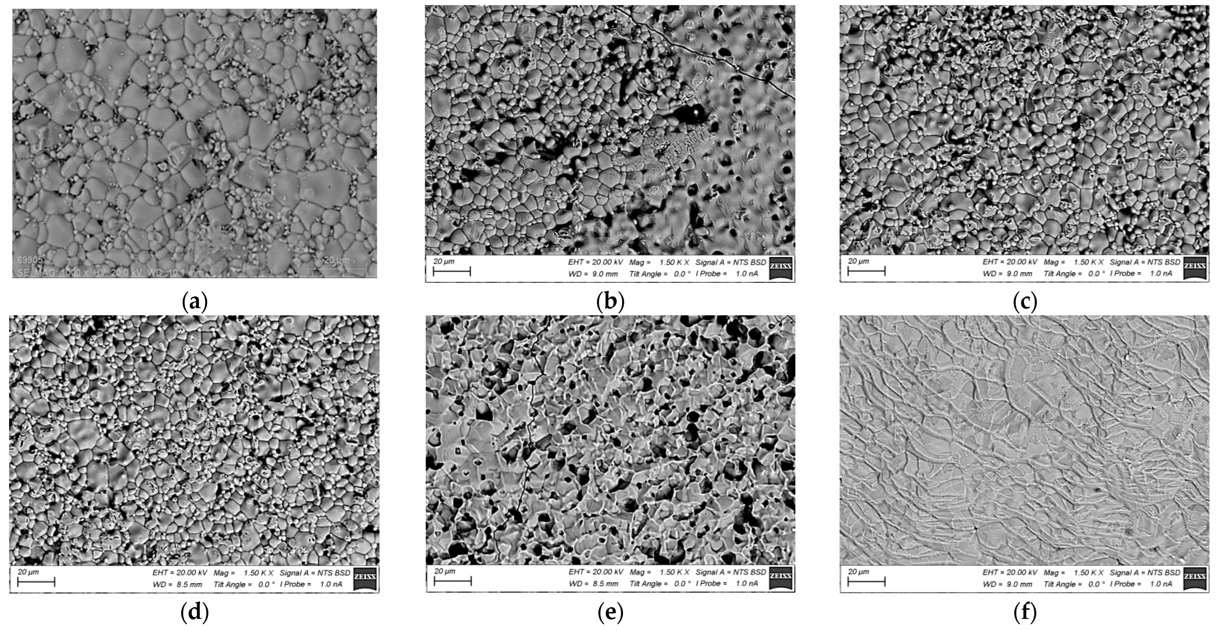
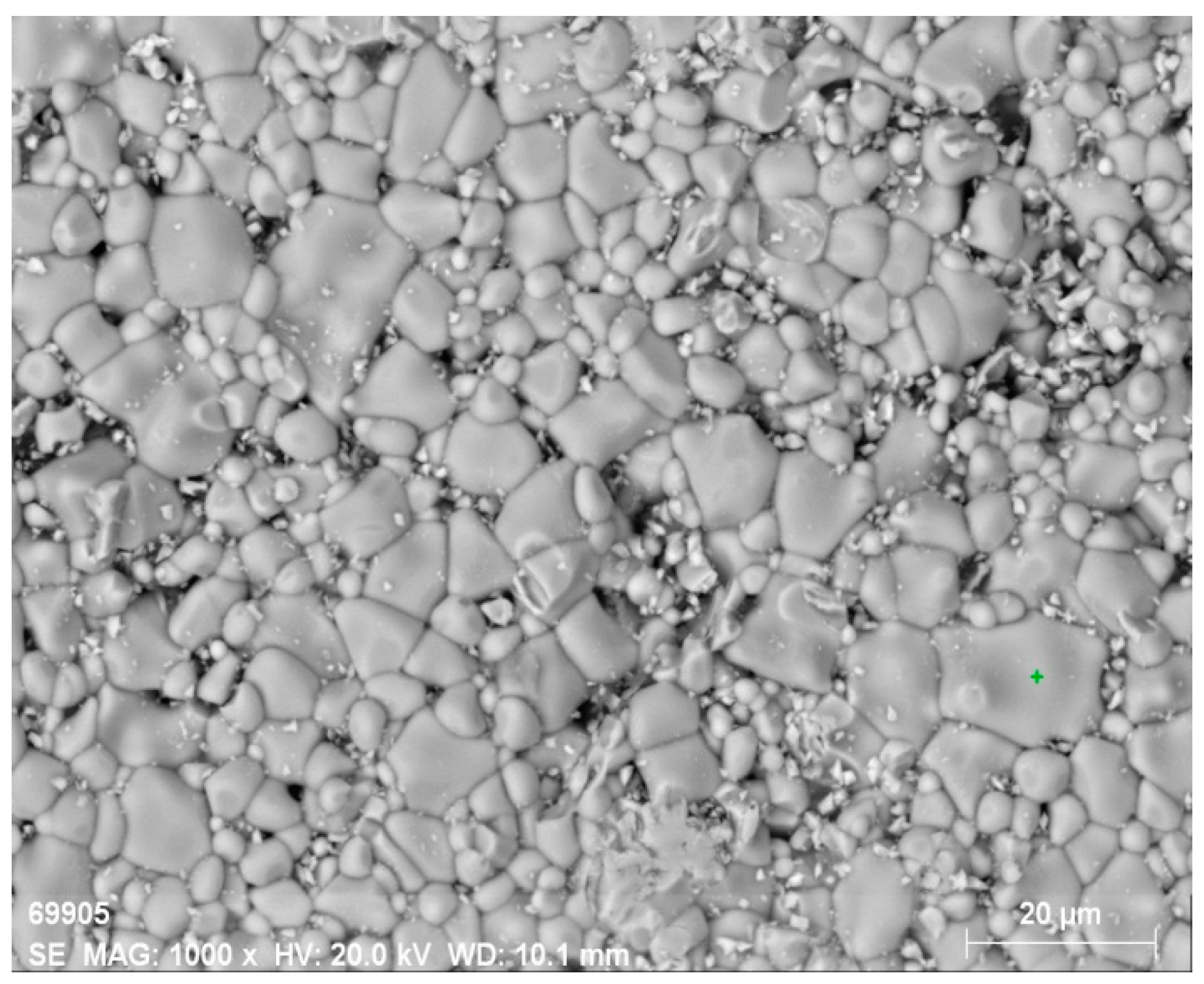
Figure 5 shows SEM images of the surface of the original ferrite and ferrite irradiated at different temperatures. The most significant change in surface structure occurs starting from a temperature of 1200 °C. The crystalline structure becomes more noticeable in the near-surface layer. Pores become more pronounced, and their quantity notably increases compared to other samples treated at lower temperatures. When the temperature reaches 1300 °C (Figure 5f), a noticeable change in surface structure is observed.
In SEM images of the surface taken at other magnifications, as shown in Figure 6, for this sample, secondary recrystallization and the formation of a periodic microstructure with a characteristic period of about 10 µm are visible. Simultaneously, the surface becomes smoother, and pores are filled with a melt that, upon further crystallization, forms a flat surface. Such surface changes have been observed before during electron beam treatment of NiZn ferrites [51]. However, the required temperatures for the material presented in this article are 200 °C higher.
The change in surface structure is accompanied by a change in phase composition. The results of measurement of elemental composition in the ferrite near-surface layer are shown in Table 4.
As a result of the treatment, the concentration of zinc decreases significantly in the near-surface layer. At the same time, the concentrations of iron and manganese decrease, while the concentration of oxygen increases. The loss of zinc leads to a significant increase in the electrical conductivity of the ferrite. 
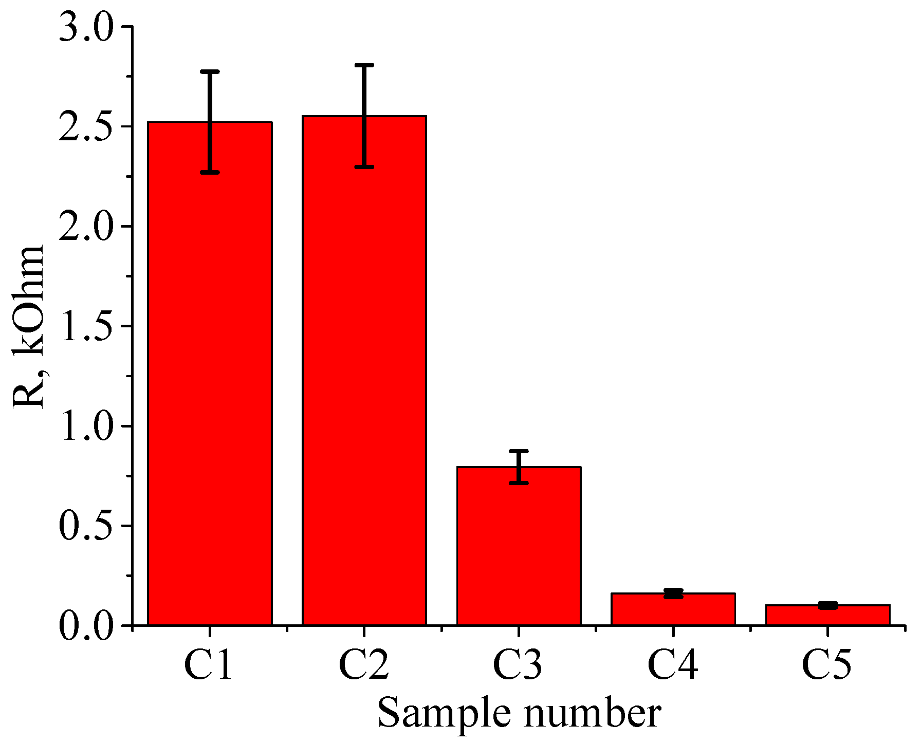
Figure 7 shows the resistance of ferrite treated at various temperatures. Even for the lowest treatment temperature, the resistance is significantly lower than in the original (untreated) state. For the original ferrite, the resistance was 30 kΩ, whereas at 900 °C, the resistance decreases by more than an order of magnitude to 2.5 kΩ (see Figure 7). Note that the decrease in resistance, unlike the structural changes, begins for samples treated at a temperature as low as 1100 °C. This dependence is presumably linked to the change in zinc content, which starts to decrease in the sample already at the minimum treatment temperature. The resistance on the untreated side of the ferrite also decreases, ranging from 3 to 3.5 kΩ.
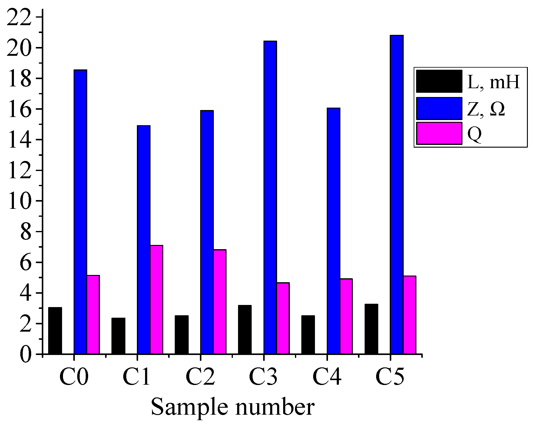
Other electrical parameters, measured at the standard frequency of 1000 Hz, do not change as much. Figure 8 shows the dependence of inductance L, impedance Z, and quality factor Q of ferrite rings on the treatment mode. Sample C0 is the untreated ferrite.
The inductance of the original sample is 3 mH, and it is changed by processing to 2.3–3.1 mH; however, no clear dependence on temperature is observed. The quality factor increases slightly from 5 for the original sample to 7 for the sample processed at 900 °C; the low value of quality factor indicates a significant attenuation of oscillations in the coil wound for measurements on this ferrite. The impedance varies over the range from 15 to 20 ohms, and reaches its maximum value at a processing temperature of 1100 °C.

4.2. Pulse Mode Treatment Results

Pulse treatment regimes for the five samples are shown in Table 5. For all samples, the emission current Ie was 20 A (14 A electron beam current), the electron beam energy was 9 keV, and the pulse repetition frequency was 0.5 Hz. With the increase in pulse duration, the energy density J increased, which should affect the surface structure.
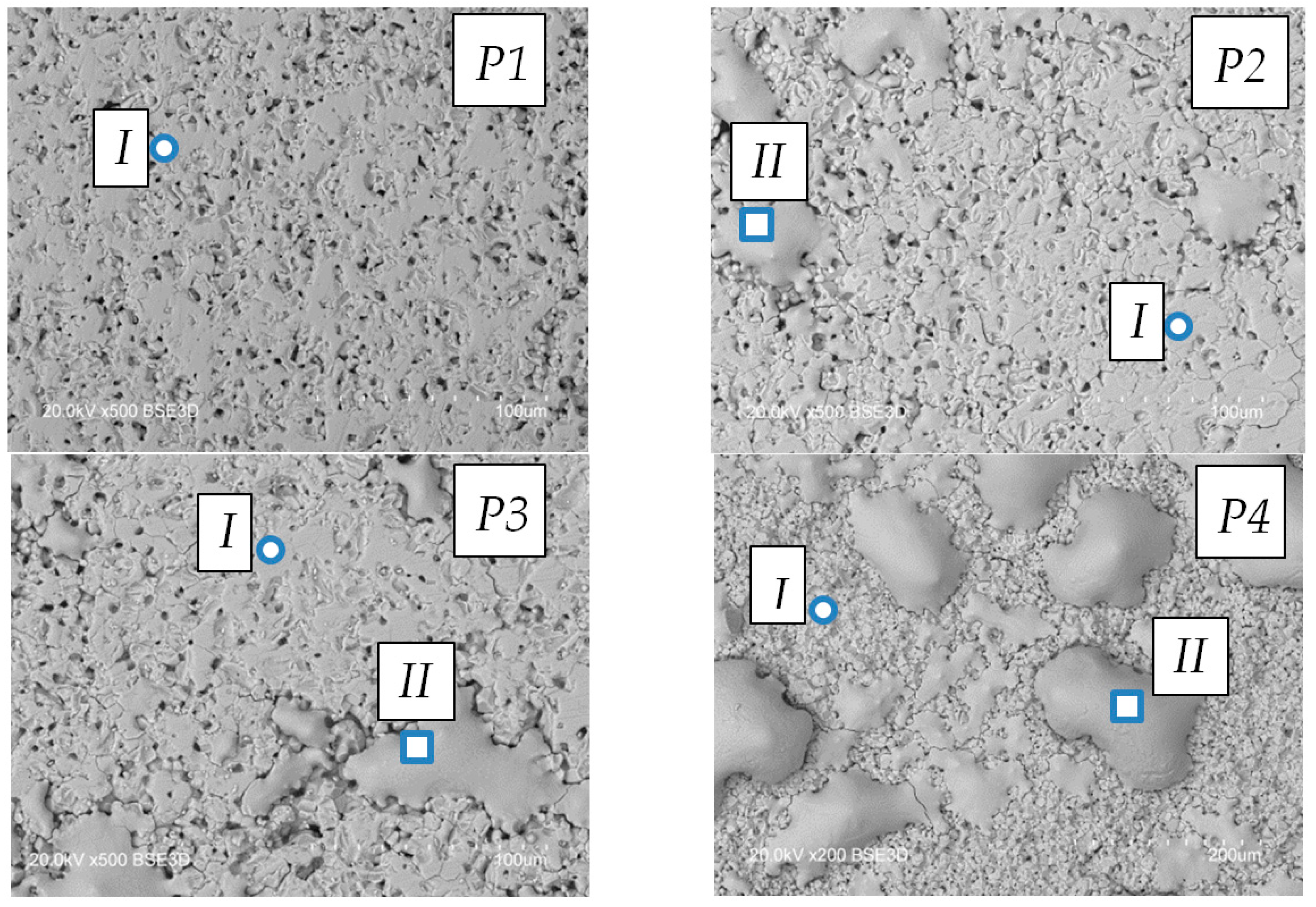
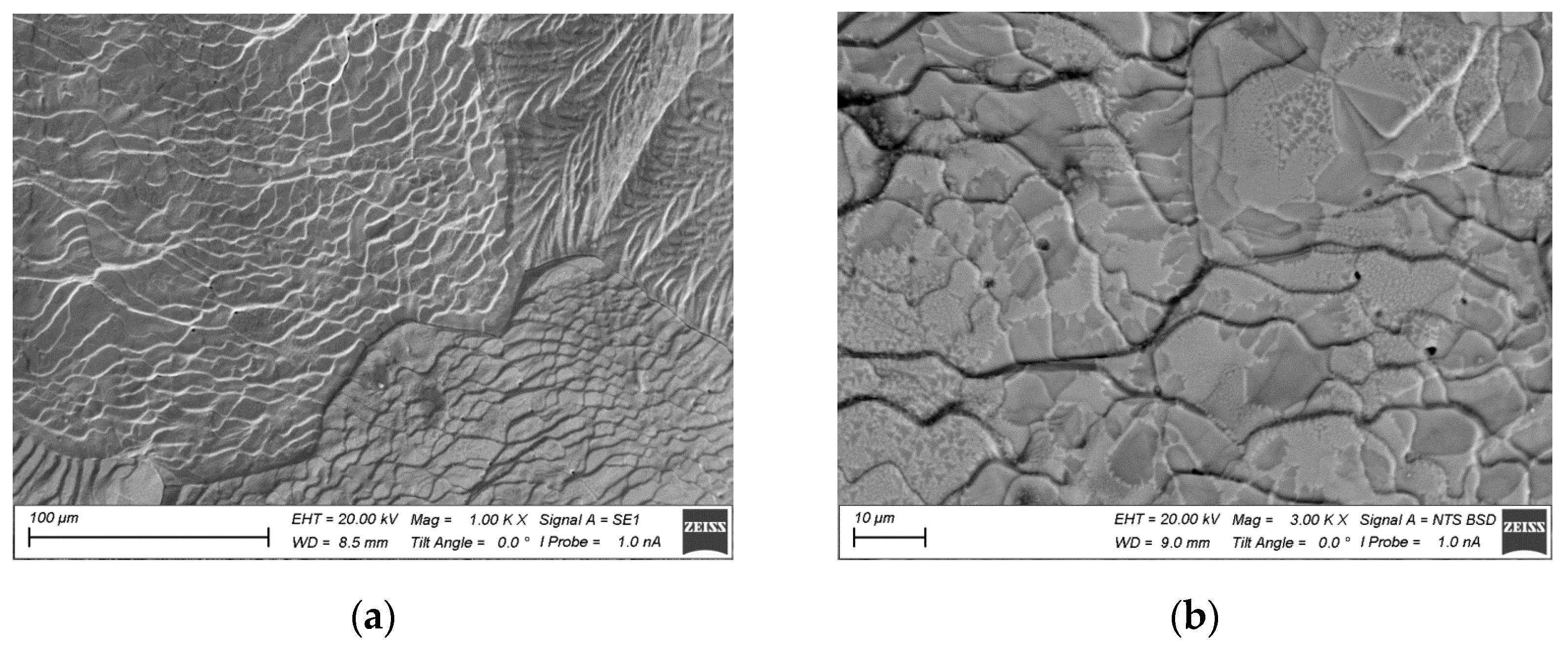
The surface structure of the ferrite after pulse treatment differs from that treated in continuous mode, as shown in Figure 9. For sample P1, no significant changes in surface structure are observed. With increase in pulse duration, the formation of spread-out areas resembling small droplets can be observed, with the droplet sizes growing as the pulse duration increases. For pulse duration 1.5 ms (J = 15 J/cm²), the droplet sizes do not exceed 20–30 μm. For pulse duration 3 ms (J = 30 J/cm²), the surface exhibits larger droplets with a characteristic size up to 200 μm, as well as smaller formations with sizes 50–100 μm. Further increasing the pulse duration while maintaining the current and accelerating voltage at the same level leads to the destruction of the ferrite. Therefore, samples treated with τd > 3 ms (J > 30 J/cm2) were not investigated.
It is evident that, during pulsed electron beam irradiation, the ferrite surface is heated to its melting temperature and possibly higher. Due to capillary forces, the molten layer accumulates into droplets, which subsequently serve as regions of concentrated molten material. To confirm the possibility of heating the surface to melting temperatures, temperature calculations were performed, which will be presented in the following section.
Changes in surface structure are also reflected in its elemental composition. Table 6 shows the variation in elemental composition of the near-surface layer of Mn-Zn ferrite after pulse electron beam treatment at different surface temperatures. Measurement points for composition are marked with circles in Figure 9. As seen from Table 5, with an increase in pulse duration, the oxygen content increases slightly in Zone I and the zinc concentration decreases. The most significant change in zinc content is observed in droplets solidified on the surface. Data were obtained from areas marked with squares in Figure 9. The zinc content decreases by more than an order of magnitude, indicating high temperature in these regions.
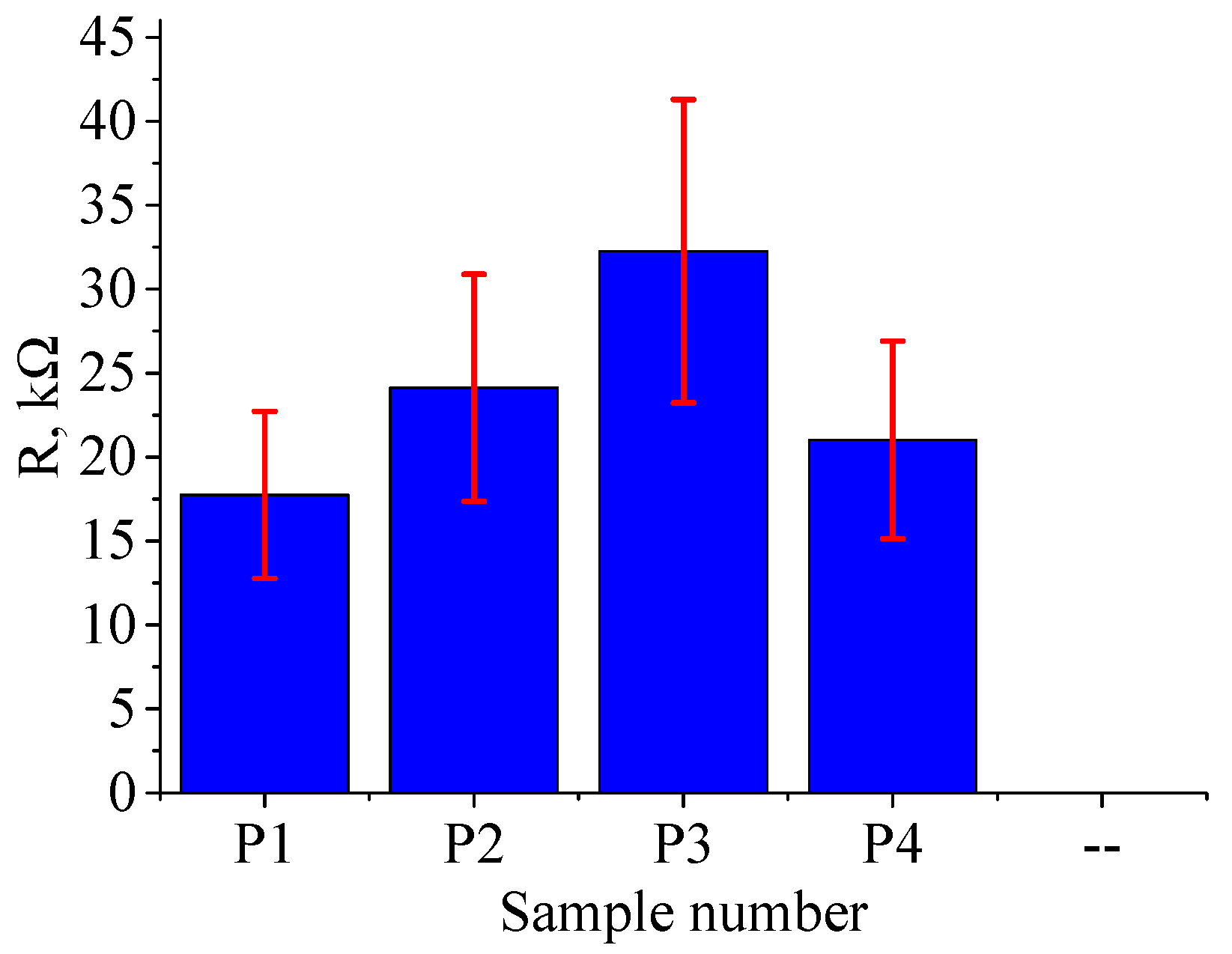
Unlike continuous mode treatment, the resistance of the surface after pulse treatment was found to be dependent on the points of probe application. Figure 10 shows the dependence of ferrite resistance on treatment mode. The resistance on the untreated side ranged from 25 to 30 kΩ.
The variation in resistance values in this case exceeds 30%, which could be attributed to the fact that zinc-depleted regions are discretely distributed on the surface and do not form a continuous layer as in the case for continuous treatment.

4.3. Thermal Field Modeling

Modeling allows for calculating the temperature on the ferrite surface and within the material. The calculations used tabulated thermophysical data for Mn-Zn ferrite 2000 HM, as shown in Table 7.
Unsteady heat conduction is generally described by the Fourier–Kirchhoff equation. For a complete description of the heat conduction process in a specific case, it is necessary to specify the boundary conditions. Geometric conditions define the shape and dimensions of the object, while physical conditions are determined by the thermophysical properties of the material, including density, specific heat, and thermal conductivity. Due to the symmetry of the sample with respect to its axis, the Fourier–Kirchhoff equation in cylindrical coordinates was used for calculations. Since sample irradiation in this study occurs in a vacuum, heat transfer through convection was not considered. The unsteady heat exchange process in a vacuum is described by the two-dimensional heat conduction equation:
ρ c δ T δ t = λ δ 2 T δ r 2 + λ δ 2 T δ z 2 ,
where T is temperature, t is time, ρ is the material density, c is the specific heat of the material, λ is the thermal conductivity of the material, and r and z are coordinates.
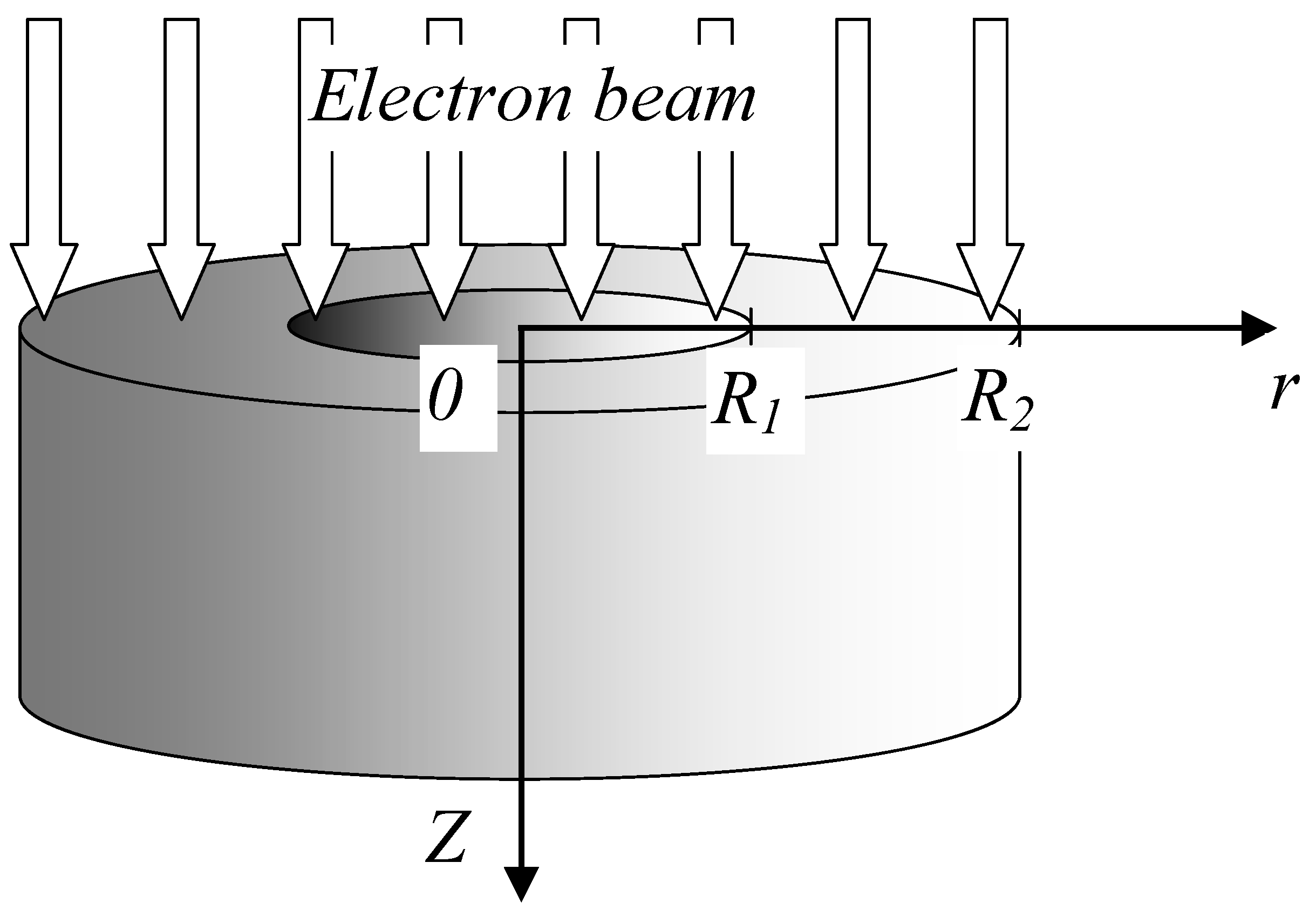
For a complete description of the process, geometric, physical, initial, and boundary conditions were defined. To determine the boundary conditions, radiation from all surfaces of the sample was considered. A uniform electron beam irradiated one of the cylinder’s faces, while the other face was placed on a massive crucible. At the beginning, the temperature of the entire sample was at room temperature, which is 30 °C.
The irradiation scheme is depicted in Figure 11. Points R1 and R2 in Figure 11 represent the inner and outer radii of the ring, respectively. The origin of the coordinate system was placed at the center of the irradiated face.
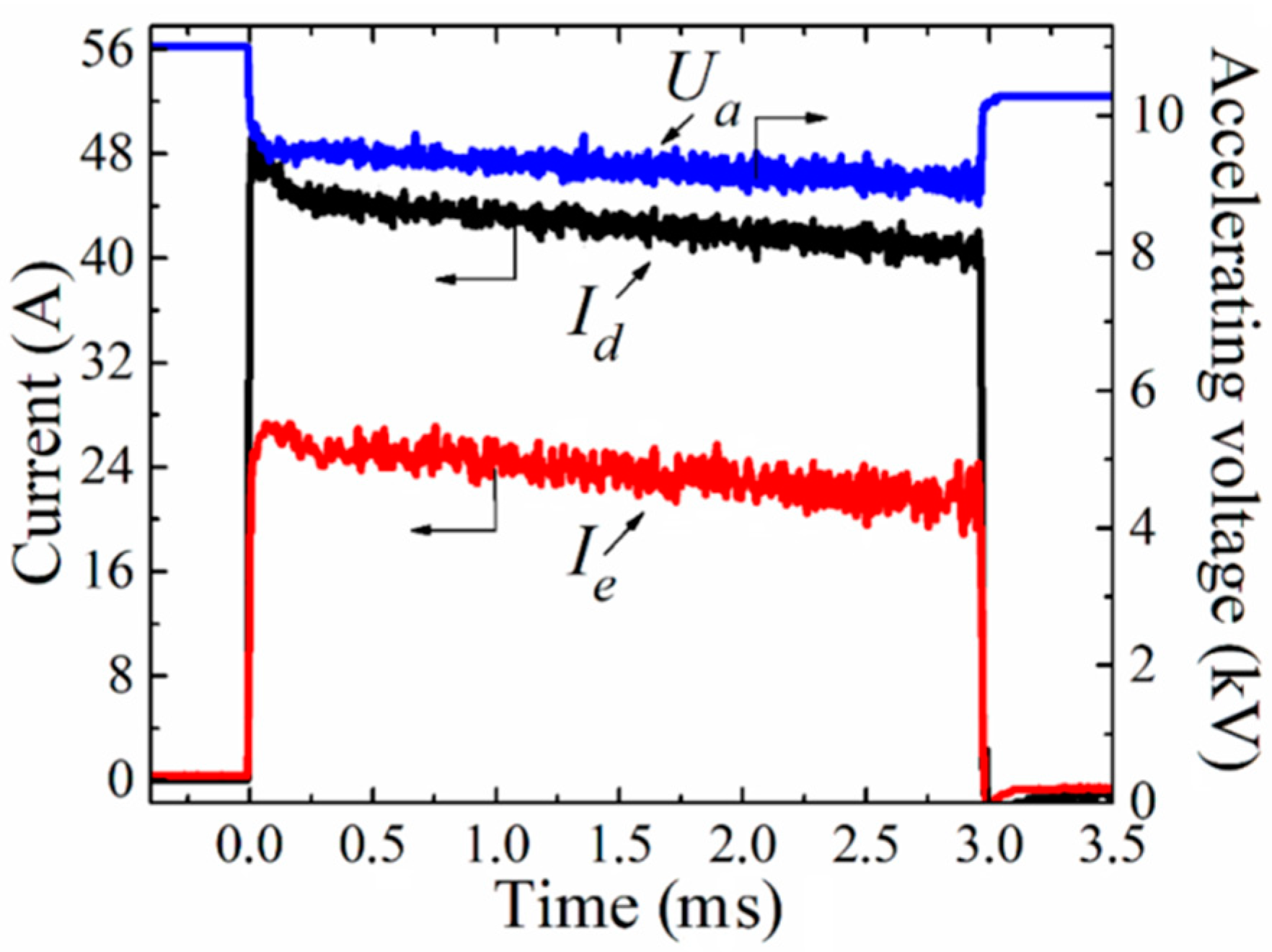
Electron beam treatment of the ferrite ring in pulsed mode was carried out at a frequency of 0.5 Hz. The emission current of the electron source was Ie = 24 A, the accelerating voltage was Ua = 9 kV, and the diameter of the electron beam was 10 mm. The pulse duration and number of pulses are shown in Table 5. The parameters of the electron beam during continuous mode treatment were accelerating voltage 8 kV, beam current 20 mA, and beam diameter 10 mm. The heat conduction equation was solved using the finite difference method.
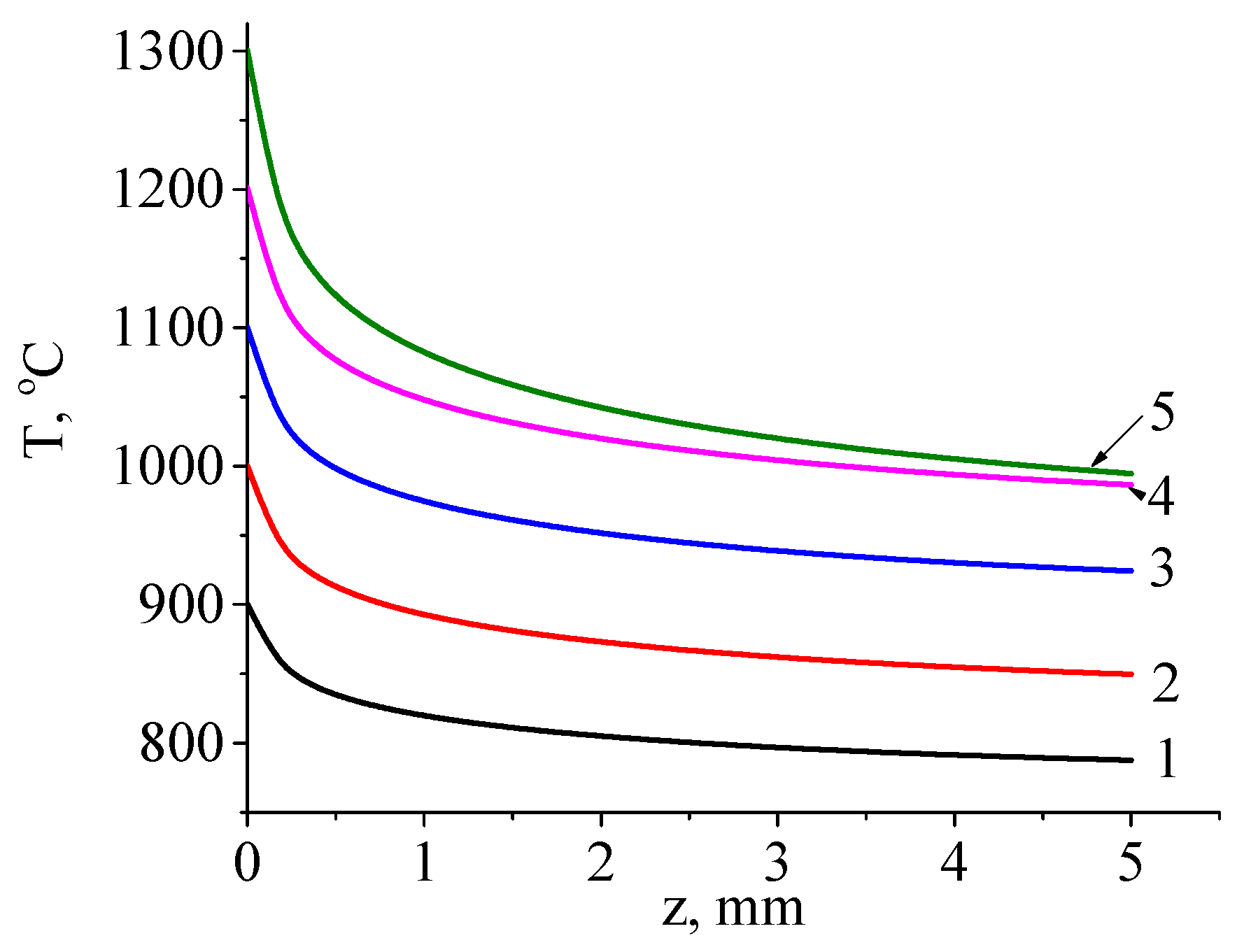
Figure 12 shows the calculated temperature distribution profiles through the thickness of the sample during irradiation with a continuous electron beam under different conditions. The modes were selected to achieve surface temperature ranging from 900 °C to 1300 °C in 100 °C increments.
In Figure 12, it is evident that, as the beam power density increases, the sample temperature rises, and as the sample temperature rises, and the temperature drop across its thickness increases from 110 °C (at a surface temperature of 900 °C) to 300 °C (at a surface temperature of 900 °C) and to 300 °C (at a surface temperature of 1300 °C). The temperature gradually decreases from the side irradiated by the electron beam to the non-irradiated side. In the case of pulsed-mode treatment, the temperature distribution pattern remains similar to the continuous case, but a greater temperature drop is observed from the irradiated to the non-irradiated side. 
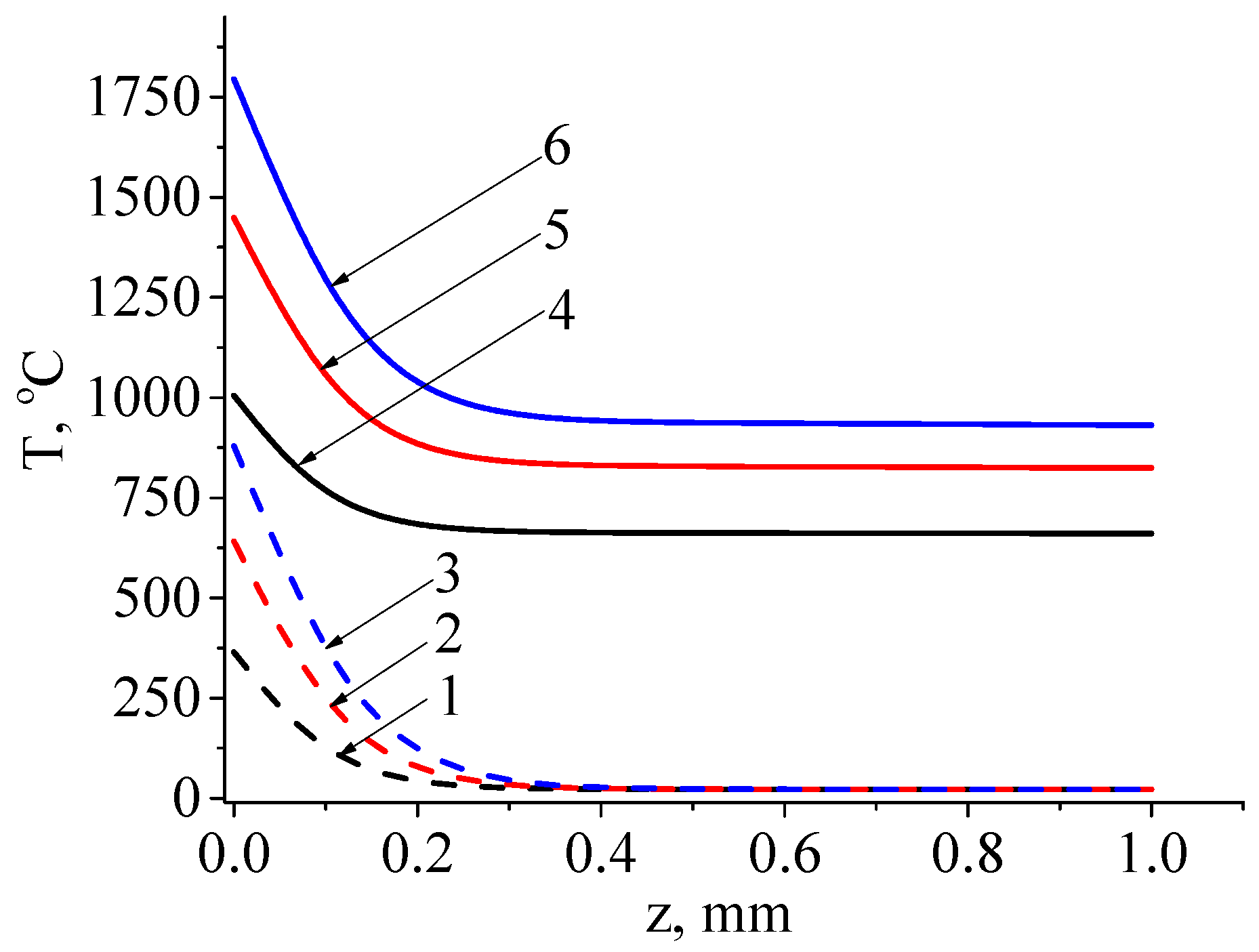
Figure 13 shows the temperature distribution on the inner surface of the ferrite after irradiation with a single electron beam pulse and a series of 500 pulses at pulse durations of 1, 2, and 3 ms. For the single-pulse case, the temperature is indicated at the end of the pulse, while for the case of a series of pulses, it is indicated at the end of the 500th pulse.
We see from Figure 13 that, with increasing pulse duration, both surface and bulk temperature of the sample rise. Additionally, the temperature drop between the surface and a layer within the sample, 0.3 mm in thickness, can reach as high as 900 °C for a single pulse and 750 °C after a series of 500 pulses. These values exceed those observed during continuous treatment. Moreover, the temperature values on the surface of the ferrite already approach or exceed the melting temperature (1567 °C) with pulse durations as short as 2 ms, as shown by curve 5 in Figure 13. This indicates the potential for surface-layer melting in the pulse-on time and recrystallization during the pulse-off time, as observed in the form of solidified islands after melting (Figure 9). Note also that the temperature distribution after continuous electron beam treatment is more homogeneous, with temperature reductions observed throughout the sample depth. Following pulsed electron beam treatment, the main temperature drop is concentrated within a layer less than 0.3 mm thick.
The differences in surface layer structure and changes in ferrite parameters after continuous and pulse treatments are attributed to variations in the nature of surface heating. Faster heating in pulse mode leads to the formation of solidified and crystallized material islands with lower zinc content. In contrast, in continuous electron beam treatment, the reduction in zinc content is observed across the entire ferrite surface, as confirmed by the decrease in resistance. Within the sample volume, it is apparent that zinc content also undergoes changes, as evidenced by the significant difference in resistance between the irradiated and non-irradiated surfaces. 
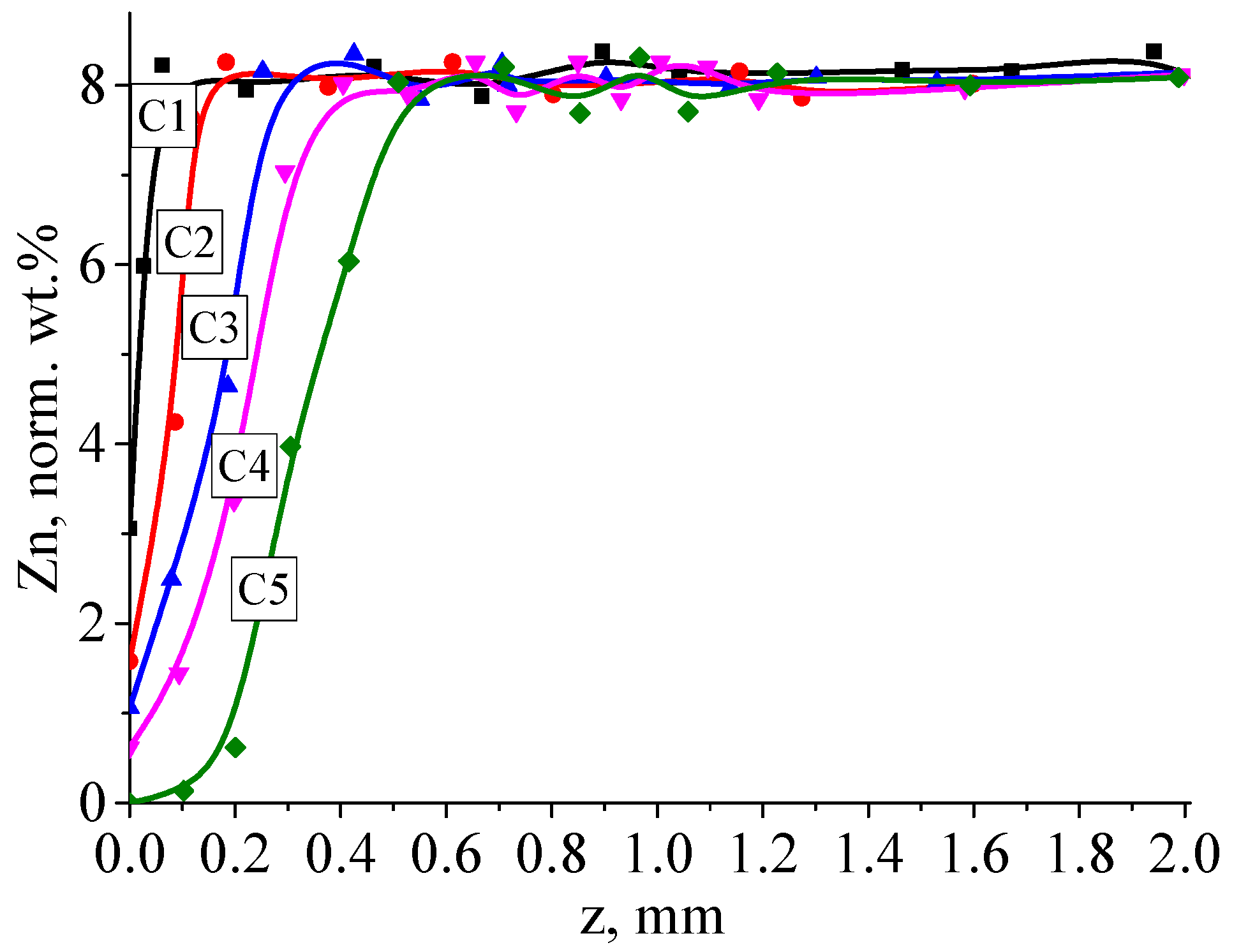
Figure 14 illustrates the distribution of zinc concentration within ferrite samples after continuous electron beam treatment under different conditions.
The formation of a region with low zinc content indirectly indicates a decrease in resistance in that area and the formation of a more electrically conducting layer. As has been established [56,57], the introduction of electrically conducting additives into the composition of ferrite, such as polymers with relatively high conductivity like polyaniline, promotes more pronounced losses and RF-absorbing properties. However, the most effective shielding efficiency is characteristic of materials with low resistance compared to ferrites. By completely reflecting electromagnetic waves, it is possible to reduce the intensity of electromagnetic radiation to zero. The presence of an electrically conducting layer in the treated material can contribute to effective electromagnetic wave shielding and expand the scope of electron beam irradiation in the creation of RF-absorbing and RF-reflecting materials.

5. Conclusions

Electron beam treatment of the surface of Mn-Zn ferrite under low vacuum pressure conditions results in microstructuring of the surface, changes in electrical properties, and alteration of the elemental composition of the ferrite. In continuous mode treatment, the most significant changes are observed when the surface temperature of the ferrite reaches 1100 °C and above. The resistance and zinc content in the near-surface layer decrease by more than an order of magnitude. Pulse mode treatment leads to the formation of solidified material particles on the surface in the form of droplets. The resistance in such treatment undergoes insignificant changes. Numerical modeling of thermal fields within the ferrite volume demonstrates that the majority of thermal energy from the pulsed electron beam is concentrated within a thin near-surface layer of the sample with a thickness of order 0.2–0.3 mm. For the case of continuous mode treatment, this layer thickness is greater, measuring at least 0.3 mm. The reduction in resistance within the ferrite layer enables its utilization as an RF-absorbing material, expanding the applications of electron beam technologies.

Author Contributions

Conceptualization, A.S.K. and A.A.Z.; Methodology, I.Y.B.; Software, I.Y.B.; Investigation, A.V.D., A.V.K. and N.S.K.; Resources, A.S.K. and A.V.D.; Writing—original draft, A.S.K.; Writing—review & editing, I.Y.B. and A.V.K. All authors have read and agreed to the published version of the manuscript.

Funding

This work was supported by the Ministry of Science and Higher Education of the Russian Federation, Grant FEWM-2021-0013.

Institutional Review Board Statement

Not applicable.

Informed Consent Statement

Not applicable.

Acknowledgments

Special thanks to Ian Brown (Berkeley Lab) for English correction and helpful discussion.

Conflicts of Interest

The authors declare no conflict of interest.

References

  1. Sugimoto, M. The Past, Present, and Future of Ferrites. J. Am. Ceram. Soc. 2004, 82, 269–280. [Google Scholar] [CrossRef]
  2. Skołyszewska, B.; Tokarz, W.; Przybylski, K.; Kąkol, Z. Preparation and magnetic properties of MgZn and MnZn ferrites. Phys. C Supercond. Appl. 2003, 387, 290–294. [Google Scholar] [CrossRef]
  3. Xie, X.; Wang, B.; Wang, Y.; Ni, C.; Sun, X.; Du, W. Spinel structured MFe2O4 (M = Fe, Co, Ni, Mn, Zn) and their composites for microwave absorption: A review. Chem. Eng. J. 2022, 428, 131160. [Google Scholar] [CrossRef]
  4. Valenzuela, R. Novel Applications of Ferrites. Phys. Res. Int. 2012, 2012, 591839. [Google Scholar] [CrossRef]
  5. Košak, A.; Makovec, D.; Žnidaršič, A.; Drofenik, M. Preparation of MnZn-ferrite with microemulsion technique. J. Eur. Ceram. Soc. 2004, 24, 959–962. [Google Scholar] [CrossRef]
  6. Thakur, P.; Chahar, D.; Taneja, S.; Bhalla, N.; Thakur, A. A review on MnZn ferrites: Synthesis, characterization and applications. Ceram. Int. 2020, 46, 15740–15763. [Google Scholar] [CrossRef]
  7. Sharma, K.; Aggarwal, N.; Kumar, N.; Sharma, A. A review paper: Synthesis techniques and advance application of Mn-Zn nano-ferrites. Mater. Today Proc. 2023, in press. [CrossRef]
  8. Thakur, P.; Taneja, S.; Sindhu, D.; Lüders, U.; Sharma, A.; Ravelo, B.; Thakur, A. Manganese Zinc Ferrites: A Short Review on Synthesis and Characterization. J. Supercond. Nov. Magn. 2020, 33, 1569–1584. [Google Scholar] [CrossRef]
  9. A Ahmed, M.; Okasha, N.; I El-Dek, S. Preparation and characterization of nanometric Mn ferrite via different methods. Nanotechnology 2008, 19, 065603. [Google Scholar] [CrossRef]
  10. Angermann, A.; Töpfer, J.; Da Silva, K.L.; Becker, K.D. Nanocrystalline Mn–Zn ferrites from mixed oxalates: Syn-thesis, stability and magnetic properties. J. Alloys Compd. 2010, 508, 433–439. [Google Scholar] [CrossRef]
  11. Jiang, J.; Ai, L.; Li, L.-C. Synthesis and magnetic performance of polyaniline/Mn–Zn ferrite nanocomposites with intrinsic conductivity. J. Mater. Sci. 2009, 44, 1024–1028. [Google Scholar] [CrossRef]
  12. Yuvaraj, S.; Manikandan, N.; Vinitha, G. Influence of copper ions on structural and non-linear optical properties in manganese ferrite nanomaterials. Opt. Mater. 2017, 73, 428–436. [Google Scholar] [CrossRef]
  13. Kaneva, I.I.; Kostishin, V.G.; Andreev, V.G.; Nikolaev, A.N.; Volkova, E.I. The effect of additives on the properties of bismuth Mn–Zn ferrite. Mod. Electron. Mater. 2015, 1, 76–81. [Google Scholar] [CrossRef]
  14. Qian, K.; Yao, Z.; Lin, H.; Zhou, J.; Haidry, A.A.; Qi, T.; Chen, W.; Guo, X. The influence of Nd substitution in Ni–Zn ferrites for the improved microwave absorption properties. Ceram. Int. 2020, 46, 227–235. [Google Scholar] [CrossRef]
  15. Abdel Maksoud MI, A.; El-Sayyad, G.S.; Abokhadra, A.; Soliman, L.I.; El-Bahnasawy, H.H.; Ashour, A.H. In-fluence of Mg2+ substitution on structural, optical, magnetic, and antimicrobial properties of Mn–Zn ferrite nanoparticles. J. Mater. Sci. Mater. Electron. 2020, 31, 2598–2616. [Google Scholar] [CrossRef]
  16. Lysenko, E.; Nikolaeva, S.; Surzhikov, A.; Ghyngazov, S.; Plotnikova, I.; Zhuravlev, V.; Zhuravleva, E. Electrical and magnetic properties of ZrO2-doped lithium-titanium-zinc ferrite ceramics. Ceram. Int. 2019, 45, 20148–20154. [Google Scholar] [CrossRef]
  17. Thakur, A.; Thakur, P.; Hsu, J.H. Structural, magnetic and electromagnetic characterization of In3+ substituted Mn-Zn nanoferrites. Z. Für Phys. Chem. 2014, 228, 663–672. [Google Scholar] [CrossRef]
  18. Angadi, V.J.; Anupama, A.V.; Kumar, R.; Somashekarappa, H.M.; Praveena, K.; Rudraswamy, B.; Sahoo, B. Evidence of structural damage in Sm and Gd co-doped Mn–Zn ferrite ceramics due to high-energy gamma irradiation. Ceram. Int. 2016, 42, 15933–15939. [Google Scholar] [CrossRef]
  19. Hakeem, A.; Alshahrani, T.; Farid, H.M.T.; Khan, A.R.; Alhossainy, M.H.; Laref, A.; Ali, I. Manganese-based spinel ferrites for microwave absorption. J. Mater. Sci. Mater. Electron. 2021, 32, 2557–2563. [Google Scholar] [CrossRef]
  20. Aman, S.; Ahmad, N.; Alhossainy, M.; Albalawi, H.; Morsi, M.; Al-Muhimeed, T.I.; AlObaid, A.A. Structural, magnetic, electrical and microwave properties of spinel ferrites. J. Rare Earths 2022, 40, 443–450. [Google Scholar] [CrossRef]
  21. Liu, D.; Gao, S.; Jin, R.; Wang, F.; Chu, X.; Gao, T.; Wang, Y. Enhanced soft magnetic properties of iron powders through coating MnZn ferrite by one-step sol–gel synthesis. Chin. Phys. B 2019, 28, 057503. [Google Scholar] [CrossRef]
  22. Huang, J.; Liu, Y.; Li, Y.; Liu, X. Microwave electromagentic and absorption properties of AFe2O4 (A = Ni, Mn, Zn) ferrites. In Proceedings of the International Conference on Manufacturing Construction and Energy Engineering (MCEE), Hong Kong, China, 17–18 August 2016; pp. 17–18. [Google Scholar]
  23. Petrescu, L.-G.; Petrescu, M.-C.; Ioniță, V.; Cazacu, E.; Constantinescu, C.-D. Magnetic Properties of Manganese-Zinc Soft Ferrite Ceramic for High Frequency Applications. Materials 2019, 12, 3173. [Google Scholar] [CrossRef]
  24. You, C.; Fan, X.; Tian, N.; He, J. Improved electromagnetic microwave absorption of the annealed pre-sintered precursor of Mn–Zn ferrite. J. Magn. Magn. Mater. 2015, 381, 377–381. [Google Scholar] [CrossRef]
  25. Sun, K.; Li, Y.; Feng, S.; Gao, Q.; Wang, Z.; Wei, X.; Ju, L.; Fan, R. Optimizing the Soft Magnetic Properties of Mn-Zn Ferrite by a Proper Control of Sintering Process. J. Electron. Mater. 2021, 50, 1467–1473. [Google Scholar] [CrossRef]
  26. Vovk, S.; Füzer, J.; Dobák, S.; Kollár, P.; Bureš, R.; Fáberová, M.; Tsakaloudi, V.; Zaspalis, V. Soft magnetic composite based on iron in sintered Mn–Zn ferrite matrix without non-magnetic coating. Ceram. Int. 2023, 49, 30137–30146. [Google Scholar] [CrossRef]
  27. Džunuzović, A.S.; Ilić, N.I.; Petrović, M.V.; Bobić, J.D.; Stojadinović, B.; Dohčević-Mitrović, Z.; Stojanović, B.D. Structure and properties of Ni–Zn ferrite obtained by auto-combustion method. J. Magn. Magn. Mater. 2015, 374, 245–251. [Google Scholar] [CrossRef]
  28. Hu, P.; Yang, H.B.; Pan, D.A.; Wang, H.; Tian, J.J.; Zhang, S.G.; Wang, X.-F.; Volinsky, A.A. Heat treatment effects on microstructure and magnetic properties of Mn–Zn ferrite powders. J. Magn. Magn. Mater. 2010, 322, 173–177. [Google Scholar] [CrossRef]
  29. Özçelik, S.; Yalçın, B.; Arda, L.; Santos, H.; Sáez-Puche, R.; Angurel, L.A.; Fuente, G.F.D.L.; Özçelik, B. Structure, magnetic, photocatalytic and blood compatibility studies of nickel nanoferrites prepared by laser ablation technique in distilled water. J. Alloys Compd. 2021, 854, 157279. [Google Scholar] [CrossRef]
  30. Abdalsalam, A.H.; Ati, A.A.; Abduljabbar, A.; Hussein, T.A. Structural, Optical, Electrical and Magnetic Studies of PANI/Ferrite Nanocomposites Synthesized by PLD Technique. J. Inorg. Organomet. Polym. Mater. 2019, 29, 1084–1093. [Google Scholar] [CrossRef]
  31. Mohapatra, P.P.; Dobbidi, P. Thickness tuneable dielectric, optical and magnetic response of lithium ferrite thin films deposited by pulsed laser deposition. Thin Solid Film. 2023, 774, 139845. [Google Scholar] [CrossRef]
  32. Surzhikov, A.P.; Malyshev, A.V.; Petrova, A.B.; Sheveleva, E.A. Microstructure Formation of LiTiZn Ferrite Ceramics during Radiation-Thermal Sintering. Mater. Sci. Forum 2019, 970, 265–275. [Google Scholar] [CrossRef]
  33. Stary, O.; Prague, P.C.V.V. Effect of normalizing heating of ferrite compacts on compaction during radiation-thermal sintering. Eurasian Phys. Tech. J. 2021, 18, 11–14. [Google Scholar] [CrossRef]
  34. Malyshev, A.V.; Lysenko, E.N.; Sheveleva, E.A.; Surzhikova, O.A.; Aryngazin, A.K. Relationship between magnetic properties and microstructure of ferrites during sintering in radiation and radiation-thermal conditions. Eurasian Phys. Tech. J. 2021, 18, 3–8. [Google Scholar] [CrossRef] [PubMed]
  35. Yang, Y.; Liu, L.; Zhu, H.; Bao, N.; Ding, J.; Chen, J.; Yu, K. Critical Control of Highly Stable Nonstoichiometric Mn–Zn Ferrites with Outstanding Magnetic and Electromagnetic Performance for Gigahertz High-Frequency Applications. ACS Appl. Mater. Interfaces 2020, 12, 16609–16619. [Google Scholar] [CrossRef] [PubMed]
  36. Martinson, K.; Ivanov, A.; Panteleev, I.; Popkov, V. Effect of sintering temperature on the synthesis of LiZnMnFe microwave ceramics with controllable electro/magnetic properties. Ceram. Int. 2021, 47, 30071–30081. [Google Scholar] [CrossRef]
  37. Hu, J.; Li, Z.; Yu, H.; Zhong, X.; Liu, Z.; Long, K.; Li, J. Modifying the Soft Magnetic Properties of Mn-Zn Ferrites by Ce2O3-Doping and Sintering Temperature Optimization. J. Electron. Mater. 2020, 49, 6501–6509. [Google Scholar] [CrossRef]
  38. Khatun, N.; Hossain, M.S.; Begum MH, A.; Islam, S.; Tanvir, N.I.; Bhuiyan, R.H.; Al-Mamun, M. Effect of sintering temperature on structural, magnetic, dielectric and optical properties of Ni–Mn–Zn ferrites. J. Adv. Dielectr. 2021, 11, 2150028. [Google Scholar] [CrossRef]
  39. Almessiere, M.A.; Slimani, Y.; Trukhanov, A.V.; Sadaqat, A.; Korkmaz, A.D.; Algarou, N.A.; Aydın, H.; Baykal, A.; Toprak, M.S. Review on functional bi component nano composites based on hard/soft ferrites: Structural, magnetic, electrical and microwave absorption properties. Nano Struct. Nano Objects 2021, 26, 100728. [Google Scholar] [CrossRef]
  40. Kostishin, V.G.; Vergazov, R.M.; Andreev, V.G.; Bibikov, S.B.; Podgornaya, S.V.; Morchenko, A.T. Effect of the microstructure on the properties of radio-absorbing nickel-zinc ferrites. Russ. Microelectron. 2011, 40, 574–577. [Google Scholar] [CrossRef]
  41. Lu, Y.-F.; Takai, M. Surface damage in a Mn-Zn ferrite induced by laser chemical etching. J. Appl. Phys. 1993, 73, 158–162. [Google Scholar] [CrossRef]
  42. Lu, Y.F.; Takai, M.; Nagamoto, S.; Namba, S. Laser-induced dry chemical etching of Mn-Zn ferrite in CCl2F2 atmosphere. Appl. Phys. B 1991, 53, 39–45. [Google Scholar] [CrossRef]
  43. Malyshev, A.; Lysenko, E.; Vlasov, V.; Nikolaeva, S. Electromagnetic properties of Li0.4Fe2.4Zn0.2O4 ferrite sintered by continuous electron beam heating. Ceram. Int. 2016, 42, 16180–16183. [Google Scholar] [CrossRef]
  44. Savruk, E.V.; Smirnov, S.V. The modification of Mn-Zn-ferrite surface by a low-energy electron beam. In Proceedings of the 2013 14th International Conference of Young Specialists on Micro/Nanotechnologies and Electron Devices, Novosibirsk, Russia, 1–5 July 2013; IEEE: Piscataway, NJ, USA; pp. 41–42. [Google Scholar]
  45. Lysenko, E.N.; Vlasov, V.A.; Malyshev, A.V.; Surzhikov, A.P. Structural and magnetic properties of lithium-substituted ferrite ceramics sintered by continuous electron beam heating. Nucl. Instrum. Methods Phys. Res. Sect. B Beam Interact. Mater. At. 2020, 470, 28–31. [Google Scholar] [CrossRef]
  46. Kostishyn, V.G.; Komlev, A.S.; Korobeynikov, M.V.; Bryazgin, A.A.; Shvedunov, V.I.; Timofeev, A.V.; Mikhailenko, M.A. Effect of a Temperature Mode of Radiation-Thermal Sintering the Structure and Magnetic Properties of Mn-Zn-Ferrites; Sumy State University: Oblast, Ukraine, 2015. [Google Scholar]
  47. Lokhande, R.M.; Vinayak, V.; Mukhamale, S.V.; Khirade, P.P. Gamma radiation shielding characteristics of various spinel ferrite nanocrystals: A combined experimental and theoretical investigation. RSC Adv. 2021, 11, 7925–7937. [Google Scholar] [CrossRef]
  48. Raghuvanshi, S.; Tiwari, P.; Kane, S.; Avasthi, D.; Mazaleyrat, F.; Tatarchuk, T.; Mironyuk, I. Dual control on structure and magnetic properties of Mg ferrite: Role of swift heavy ion irradiation. J. Magn. Magn. Mater. 2019, 471, 521–528. [Google Scholar] [CrossRef]
  49. Naik, P.P.; Tangsali, R.B.; Sonaye, B.; Sugur, S. Radiation induced structural and magnetic transformations in nanoparticle MnxZn(1−x)Fe2O4 ferrites. J. Magn. Magn. Mater. 2015, 385, 377–385. [Google Scholar] [CrossRef]
  50. Angadi, V.; Anupama, A.; Kumar, R.; Choudhary, H.; Matteppanavar, S.; Somashekarappa, H.; Rudraswamy, B.; Sahoo, B. Composition dependent structural and morphological modifications in nanocrystalline Mn-Zn ferrites induced by high energy γ-irradiation. Mater. Chem. Phys. 2017, 199, 313–321. [Google Scholar] [CrossRef]
  51. Karanskij, V.V.; Smirnov, S.V.; Klimov, A.S.; Savruk, E.V. Gradient Structures of Ni–Zn Ferrites for Electromagnetic Radiation Protection Devices. Inorg. Mater. Appl. Res. 2021, 12, 1185–1190. [Google Scholar] [CrossRef]
  52. A Burdovitsin, V.; Klimov, A.S.; Medovnik, A.V.; Oks, E.M. Electron beam treatment of non-conducting materials by a fore-pump-pressure plasma-cathode electron beam source. Plasma Sources Sci. Technol. 2010, 19, 055003. [Google Scholar] [CrossRef]
  53. Karansky, V.; Klimov, A.; Smirnov, S. Structural transformations in Mn–Zn ferrite under low-energy electron beam treatment. Vacuum 2020, 173, 109115. [Google Scholar] [CrossRef]
  54. Klimov, A.; Bakeev, I.; Oks, E.; Zenin, A. Forevacuum plasma source of continuous electron beam. Laser Part. Beams 2019, 37, 203–208. [Google Scholar] [CrossRef]
  55. Kazakov, A.V.; Medovnik, A.V.; Oks, E.M.; Panchenko, N.A. Broad-beam plasma-cathode electron beam source based on a cathodic arc for beam generation over a wide pulse-width range. Rev. Sci. Instrum. 2020, 91, 093304. [Google Scholar] [CrossRef] [PubMed]
  56. Ali, N.N.; Al-Marjeh, R.A.-Q.B.; Atassi, Y.; Salloum, A.; Malki, A.; Jafarian, M. Design of lightweight broadband microwave absorbers in the X-band based on (polyaniline/MnNiZn ferrite) nanocomposites. J. Magn. Magn. Mater. 2018, 453, 53–61. [Google Scholar] [CrossRef]
  57. Saini, M.; Shukla, R.; Kumar, A. Cd2+ substituted nickel ferrite doped polyaniline nanocomposites as effective shield against electromagnetic radiation in X-band frequency. J. Magn. Magn. Mater. 2019, 491, 165549. [Google Scholar] [CrossRef]
Figure 1. SEM photograph of the surface of unprocessed 2000 NM ferrite.
Coatings 13 01766 g001
Figure 2. Experimental setup for electron beam irradiation of ferrites in continuous mode.
Coatings 13 01766 g002
Figure 3. Experimental setup for electron beam irradiation of ferrites in pulsed mode.
Coatings 13 01766 g003
Figure 4. Typical oscillograms of discharge current (Id), emission current (Ie), and beam-accelerating voltage (Ua).
Coatings 13 01766 g004
Figure 5. SEM images of the surface of the original ferrite (a) and ferrite irradiated at different temperatures: (b) 900 °C; (c) 1000 °C; (d) 1100 °C, (e) 1200 °C, (f) 1300 °C. Magnification: 1500×.
Coatings 13 01766 g005
Figure 6. SEM image of the surface of ferrite irradiated at a temperature of 1300 °C. Magnification: (a) 1000×; (b) 3000×.
Coatings 13 01766 g006
Figure 7. Resistance of manganese–zinc ferrite on the irradiated side for treatment at various temperatures.
Coatings 13 01766 g007
Figure 8. Electrical parameters of manganese–zinc ferrite at various temperatures.
Coatings 13 01766 g008
Figure 9. SEM images of the surfaces of ferrites irradiated under different conditions. Circles and squares indicate areas for elemental composition measurements. Magnification 500×.
Coatings 13 01766 g009
Figure 10. Resistance of Mn-Zn ferrite on the pulse-treated side for different treatment modes.
Coatings 13 01766 g010
Figure 11. Irradiation scheme.
Coatings 13 01766 g011
Figure 12. Temperature distribution during continuous electron beam treatment with different power densities: (1) 150 W/cm2; (2) 190 W/cm2; (3) 210 W/cm2; (4) 250 W/cm2; (5) 400 W/cm2.
Coatings 13 01766 g012
Figure 13. Temperature distribution in ferrite samples irradiated with pulses of different duration, after a single pulse (1, 2, 3), and after a series of 500 pulses (4, 5, 6). Pulse length: 1 ms (1, 4), 2 ms (2, 5), and 3 ms (3, 6).
Coatings 13 01766 g013
Figure 14. Distribution of zinc concentration in ferrite samples under different conditions of continuous electron beam treatment.
Coatings 13 01766 g014
Table 1. Parameters of 2000 NM ferrite.
ParameterMn0.6Zn0.4Fe3O3
Initial magnetic permeability 2000
Amplitude magnetic permeability, µa3000
Density, g/cm34.7
Working frequency rangeUp to 10 MHz
Saturation induction, mT (at 25 °C)350
Remanence, Br, mT (at 25 °C)100
Coercive force, Hc, A/m (at 25 °C)16
Curie temperature Tc, °C (at 25 °C)200
Specific electrical resistivity, ρ, Ohm/m5
Table 2. Elemental composition of unprocessed 2000 NM ferrite.
Element[norm. wt.%][norm. at.%]
Carbon1.43.8
Oxygen26.954.9
Manganese13.88.2
Iron49.729.1
Zinc8.24.1
Table 3. Continuous electron beam treatment conditions.
SampleC1C2C3C4C5
Temperature, °C9001000110012001300
Table 4. Composition of ferrite irradiated under different conditions.
ElementC1C2C3C4C5
O, %53.353.554.955.360.8
Mn, %10.711.410.910.79.2
Fe, %33.133.932.633.529.9
Zn, %3.01.21.00.50
Table 5. Parameters of 2000 NM ferrite.
Sample No.Pulse Duration τd, msNumber of Pulses NEnergy Density J in Pulse, J/cm²
P1175010
P21.550015
P3250020
P4350030
Table 6. Composition of ferrite pulse-irradiated under different conditions.
ElementP1P2P3P4
Zone IZone IIZone IZone IIZone IZone II
C, %7.02.01.91.41.52.11.9
O, %25.325.627.625.417.626.130.6
Al, %0.30.10.90.20.40.20.2
Si, %-0.00.00.00.20.10.1
Mn, %12.914.217.814.222.213.616.2
Fe, %46.850.751.551.957.551.350.5
Zn, %7.67.90.96.80.66.80.6
Table 7. Thermophysical parameters of ferrites.
Parameter2000 HM Mn-Zn Ferrite
Density, kg/m34500
Thermal conductivity, W/(m·K)650
Specific heat, J/(kg·K)2.8
Disclaimer/Publisher’s Note: The statements, opinions and data contained in all publications are solely those of the individual author(s) and contributor(s) and not of MDPI and/or the editor(s). MDPI and/or the editor(s) disclaim responsibility for any injury to people or property resulting from any ideas, methods, instructions or products referred to in the content.

