Article

Effect of Pore Evolution on Thermal Diffusivity and Radiation Characteristics of Thermal Barrier Coatings after High-Temperature Exposures

1
School of Electrical and Automation, Wuhu Institute of Technology, Wuhu 241006, China
2
Fujian Provincial Key Laboratory of Terahertz Functional Devices and Intelligent Sensing, School of Mechanical Engineering and Automation, Fuzhou University, Fuzhou 350108, China
3
School of Artificial Intelligence, Anhui Polytechnic University, Wuhu 241000, China
4
School of Mechanical Engineering, Anhui Polytechnic University, Wuhu 241000, China
5
Department of Automotive Engineering and Intelligent Manufacturing, Wanjiang College of Anhui Normal University, Wuhu 241008, China
6
Anhui Key Laboratory of Detection Technology and Energy Saving Devices, Anhui Polytechnic University, Wuhu 241000, China
*
Authors to whom correspondence should be addressed.
Coatings 2023, 13(10), 1675; https://doi.org/10.3390/coatings13101675
Submission received: 4 September 2023 / Revised: 20 September 2023 / Accepted: 23 September 2023 / Published: 25 September 2023

Abstract

:
Studying the impact of pores is crucial to enhancing the service performance of coatings, since they are a typical microstructure feature of thermal barrier coatings. In this paper, a coating prepared by the APS method was employed as the study object, and a scanning electron microscope and optical microscope were used to calculate the porosity after spraying or high-temperature exposures. Based on this, numerical calculations and simulations were used to evaluate the impacts of the pore structure and porosity on the heat conductivity and radiation characteristics of the coating. The results showed that, at high-temperature exposures, the horizontal pores inhibited thermal conductivity and radiation, but the column pores increased heat conductivity and radiation. The heat conductivity of the coating linearly decreased as the porosity increased, whereas the extinction coefficient increased, although at a slower and slower pace. When the porosity reached 15%, if the porosity was further increased, the thermal radiation energy did not change much, indicating that increasing the porosity would only block the heat radiation to a certain amount. This new and time-saving technique for materials research utilizing simulation and numerical computing may be utilized to optimize the microstructure of coatings to increase their service performance.

1. Introduction

With increasing demands for energy savings and pollution reductions in many nations, the thermal conversion efficiency of gas turbines and aero engines must also rise. The most straightforward and effective way to enhance efficiency is to raise the inlet temperature of gas turbines and aero engines [1]. However, increasing the inlet temperature causes gas turbine and aero engine blades to experience excessive thermal stress, causing the hot-end components to fail due to reaching the weakening point for basic mechanical characteristics in a high-temperature environment, which is fatal to gas turbines and aero engines. At the moment, the most generally utilized solutions to overcome the aforementioned challenges are substrate-material performance-enhancement technology, air-cooling technology, and thermal-barrier-coating technology [2,3,4]. The maximum inlet temperature of gas turbines and aero engines has surpassed 1600 °C, but the limit temperature that the upgraded nickel-based superalloy can tolerate is only around 1150 °C, posing new problems for the safe operation of gas turbines and aero engines [5]. The foregoing results illustrate that just improving the material characteristics is no longer sufficient to fulfill the demands of most gas turbine and aero engine applications. To that goal, researchers from several nations optimized the engine structural. A cold air layer with a low temperature is generated by placing tiny holes or slots on the surface of the hot-end components, resulting in heat insulation and cooling [6]. The most modern air-cooling technology can now only boost the working temperature of gas turbines or aero engines by around 400 °C, which is insufficient to fulfill the demands of most engines. Furthermore, the process of air-cooling technology is complicated, and the extra energy required to drive the air flow would raise the strain on the engine, reducing the engine efficiency [7]. Based on this, the United States pioneered the application of thermal-barrier-coating technology to deal with this technological difficulty in the 1950s and 1960s in order to obtain improved thermal efficiency. The application of thermal barrier coatings not only raises the engine’s working temperature but also preserves the substrate material, improving engine efficiency while increasing service life [8]. The application of thermal barrier coatings allows engine hot-end components to combine the advantages of a metal substrate’s high strength and toughness with the high-temperature resistance of a ceramic layer. Moreover, the thermal barrier coating not only lowers the temperature of the metal substrate but also enhances its thermal stress qualities.
At present, the most often used thermal barrier coating in industry is a double-layer structure, as seen in Figure 1 [9]. Atmospheric plasma spraying (APS) and electron beam physical vapor deposition (EB-PVD) are the two most used commercial procedures for generating top ceramic coatings. In comparison to the EB-PVD approach, defects such as holes and cracks occur in thermal barrier coatings prepared by the APS method [10]. The thermal barrier coating’s primary functions are to restrict heat transmission and to protect the metal substrate. Among them, the heat transmission process is divided into three parts: heat conduction in solid materials, thermal convection between pores, and radiative transfer [11]. According to heat transfer theory, the energy transfer in the first two modes of heat transfer is highly dependent on the first power of the temperature difference and requires the assistance of an external medium. Thermal radiation, in contrast, is primarily dependent on the fourth or fifth power of the temperature difference and does not require external medium assistance, indicating that the heat transfer mechanism of thermal radiation is completely different from the two other heat transfer modes, and thermal radiation is more complex. The effect of thermal radiation is more noticeable at high temperatures, where the temperature difference between the two sides of the heat transfer is substantial. As a result, it is critical to investigate the variations in heat radiation caused by different pore architectures in order to improve the service temperature and service life of thermal barrier coatings, which is also the topic of this work.
The essence of heat radiation is electromagnetic wave transmission, which also possesses wave–particle duality properties. When the object scale surpasses the wavelength of the radiation, the photon transforms into a particle, and the energy transfer is analyzed using geometrical optics. When the object size is tiny, the photon acts like a wave, which means that the macroscopic theory of thermal radiation transport cannot be properly matched in the heat radiation of the thermal barrier coating. Since the radiation problem within a thermal barrier coating is similar to that of a porous medium, the important radiation characteristic parameters must be established during the theoretical solution procedure. Reflectance, transmittance, extinction coefficient, and absorption coefficient are the radiation characteristics of thermal barrier coatings. Different parameters must be computed by selecting the proper radiative transfer model for the scenario. Domestic and international academics have undertaken extensive studies on thermal barrier coatings in recent years, although the majority of them focus on thermal shock resistance, oxidation resistance, cracking resistance, corrosion resistance, durability, and heat transmission characteristics [12,13,14,15,16]. Previous research focused on the thermal conductivity of thermal barrier coatings, specifically the influence of different microstructures on the thermal conductivity of thermal barrier coatings [17,18,19,20,21]. However, it was discovered that when the temperature surpasses 600 °C, the thermal conductivity rises fast, a phenomenon that cannot be described by standard geometrical optics, which would result in huge inaccuracies in thermal conductivity. Therefore, the effect of thermal radiation on the heat transfer of thermal barrier coatings cannot be ignored at high temperatures. Despite some advances in studies on the radiation properties of thermal barrier coatings, there are still several gaps. The fundamental reason is that as the engine’s thrust-to-weight ratio grows so does its service temperature. However, the parameters of the thermal barrier coating’s radiation characteristics at high temperatures are still insufficient, and acquiring these parameters aids in the construction of a comprehensive spectrum of the thermal barrier coating’s radiation characteristics. It also serves as a foundation for the application of theoretical models of radiation characteristics, which should aid in the discovery of the radiation transmission mechanism within the thermal barrier layer.
In summary, based on the Maxwell electromagnetic wave principle, this paper solves the problem using simulation and compares the results to those calculated using the finite-difference time-domain (FDTD) method to investigate the effect of changes in microstructure characteristics on thermal conductivity and radiation properties. The influence of various microstructural characteristics on thermal conductivity and radiation properties of APS-prepared coatings is explored in this work using a mix of experiments and simulations. The internal microstructure of the coatings is controlled by altering the spraying power, and then thermal shock is used to examined it. Based on metallographic techniques, the microstructural parameters of the thermal barrier coatings at high temperatures are obtained by combining scanning electron microscopy and optical microscopy analyses, which are then combined with simulation methods to construct the thermal conductivity and radiative properties solution models. This paper combines the methods of experiment and simulation to obtain the relevant laws first, and then use the experiment to verify them. Finally, it provides a theoretical basis and guidance for the preparation of the coating. The radiation of thermal barrier coatings after temperature exposures is further supplemented in this paper, which aids in the investigation of the effect of the microstructural features of thermal barrier coatings on thermal radiation properties. This is critical for precisely calculating the thermal radiation parameters of thermal barrier coatings during engineering applications, and it could also be used to guide the improvement of the performance of thermal barrier coatings and the prediction of their service life.

2. Materials and Methods

2.1. Sample Preparation and Characterization

The experimental substrate material in this paper was disc-shaped (25 mm × 3 mm) R683/IC45e carbon steel. Before conducting the spraying experiment, an ultrasonic cleaning machine (JP-010T, Shenzhen Jiemeng Cleaning Equipment Co., Ltd., Shenzhen, China) must be used to remove surface dust and contaminants. The substrate surface was next pretreated with a sand-blasting machine (GLPSJ-97824, Shanghai Ge Li Machinery Manufacturing Co., Ltd., Shanghai, China), which enhanced the roughness of the surface and improved the bonding force between it and the bond layer. The abrasive material used in sandblasting was white corundum sand. Following the completion of the preparatory phase, the thermal barrier coating was prepared using commercial APS spraying equipment (SJ-APS-2000A, Beijing Haifuda Technology Co., Ltd., Beijing, China). Table 1 shows the spraying parameters. In this paper, the coating porosity was regulated by power modulation. The structure of the look porosity was regulated by regulating parameters such as the speed of spraying. However, a systematic summary was not yet formed, so several attempts were needed to obtain the desired structure. The porosity of the thermal barrier coating was adjusted in this paper by altering the spraying power. To confirm the process’s stability, eight specimens were made from the same batch, and the porosity and surface roughness of these specimens were averaged. The substrate was heated before turning on the powder feeder by regulating the spray cannon through a mechanical arm, often cycling three or four times. The spraying material for the bonding layer was Ni22Cr10Al1Y (Amdry 962, Sulzer Microsystems Ltd., New York, NY, USA), which was sprayed 2–4 times to create a 30–60 μm bonding coating. The ceramic layer was sprayed 20 times to create a 200–300 μm thick coating using 8YSZ (8 wt% Y2O3 stabilized ZrO2) powder as the raw material for spraying. It was achieved by varying the power of the spray cannon in order to manage the porosity. The thermal shock test was performed on the sprayed specimens by heating the surface with a high-temperature flame to 1400–1500 °C and holding it for 70 s. The coating state was then evaluated when the surface was immediately chilled to 80 °C. The coating state was regarded as failed if it flaked more than 10%, and the number of thermal shock times at this time was recorded. Figure 2 depicts the specimen after spraying and thermal shock testing. Cracks were formed between the thermal barrier covering and the substrate during high-temperature exposures, as shown in Figure 2c. The longer the exposure time is, the cracks continue to expand until they peel off, thus failing the thermal barrier coating. The specimen cross section was sanded with 1000–3000 mesh sandpaper and then polished. The microstructure of the cross section of the sprayed thermal barrier coating was then analyzed using scanning electron microscopy (SEM, ZEISS EVO MA15, Carl Zeiss SMT Ltd., Cambridge, UK), as shown in Figure 3, and the porosity was determined using ImageJ software. A three-dimensional surface profiler (DEC-CA-3150, DECCA Precision Gauge (Shenzhen, China) Co., Ltd., Shenzhen, China) was used to observe the surface topography of the thermal barrier coating and measure the roughness, and the detection results, as shown in Figure 4, were corrected with ImageJ software and used for the subsequent numerical solving of the radiation characteristics.
The interior microstructure of the coatings created by APS spraying had three basic morphologies, as shown in Figure 3a: globular, columnar, and horizontal strip. The porosity of these three features is classified based on their lengths in the horizontal and vertical directions. The porosity is set as globular when the lengths in the horizontal and vertical directions are close to each other as well as the length of the porosity in the horizontal direction is greater than the length in the vertical direction as horizontal strip, and vice versa as columnar. The uneven microstructure within the coating was reduced to pores for future modeling and solving. While globular pores were almost isotropic, columnar and horizontal strip pores were anisotropic. Therefore, these three structures were analyzed in the subsequent numerical simulations. In addition, Figure 3a,b demonstrate the thermal barrier coatings obtained by spraying with powder feedstocks of varying particle sizes. Figure 3a,b clearly show that the finer the powder initial particle size is, the lower the porosity is under the same process conditions. The finer the particle size of the powder is, the greater the possibility is of full fusion during the spraying process, and the greater the likelihood of fusion with other particles. At the same time, the pores of tiny-particle-size powders in unmelted contact with each other were smaller than those of coarse particle size powders. As a result, the pore structure might be modified based on the powder raw material and spraying process parameters to fulfill the goal of boosting service temperature and extending life.
The surface roughness of the thermal barrier coating, as measured by a three-dimensional surface profiler, ranged between Rz0.1 and Rz6.3, which corresponded to the observed values. Hence, for the computation of the radiative characteristics, the surface roughness was randomly set to 0.1, 0.2, 0.4, 0.8, 1.6, 3.2, or 6.3.

2.2. Thermal Conductivity Solution Model

The key to addressing thermal conductivity was to generate a porous medium model of the thermal barrier coating, though its interior microstructure was exceedingly complicated, so reproducing its internal structure entirely using present approaches was challenging. The pores inside the coating had a globular form as well as horizontal and vertical strip structures. Based on the foregoing features, the four-parameter stochastic generation method, QSGS, was chosen to build the porous medium model [22], which could swiftly alter pore size, occupancy proportion, and shape, as shown in Figure 5. After obtaining the model, the thermal conductivity was solved using the thermal lattice Boltzmann method (LBM) [23], and the solution equation was provided in formula (1), after which the structure of the model might be changed and the changes in thermal conductivity compared.
k e f f = L q d A Δ T d A
where q denotes the density of the heat flow through, L denotes the length along the direction of the heat flow, and Δ T is the temperature difference between the upper and lower boundaries.

2.3. Radiation Characterization Solution Model

Maxwell’s equation describes thermal radiation, and the radiation fields of the scattering system are all controlled by Maxwell’s equation [24]. As a result, solving Maxwell’s equations theoretically allows one to determine the radiation characteristic parameters. Among them, the FDTD method is a mature numerical solution method, which is particularly suitable for complicated geometric areas [25]. The FDTD computational process is solved by utilizing the difference between time and space, making the electromagnetic wave propagation process easier to compute which has advantages in the complex structural problems of this paper. The following equation expresses the FDTD method for solving Maxwell’s equations.
× H = ε E t + σ E
× E = μ H t σ m H
where E and H represent the electric and magnetic field components, respectively; ε represents the dielectric constant of the thermal barrier coating; μ is the coefficient of magnetic permeability; σ represents the electrical conductivity; and σ m represents the magnetic permeability. The radiation intensity can be expressed by the energy, S, in the electromagnetic field, so the thermal radiation calculation can be expressed as the following equation.
S ( x , y ) = 1 T 0 T | E × H |   d t
where T = 2π/ω is the period of the radiated wave. Thus, the above formula can be further rewritten as S ( x , y ) = I ( x , y ) d Ω , and the thermal radiation characteristic parameters can be deduced from the radiation intensity, I. In this paper, Maxwell’s equations are solved by FDTD method to obtain the thermal conductivity coefficients, while the model is constructed by QSGS algorithm to simulate the radiation properties of the solved coating. All the work is completed based on MATLAB software.

3. Results

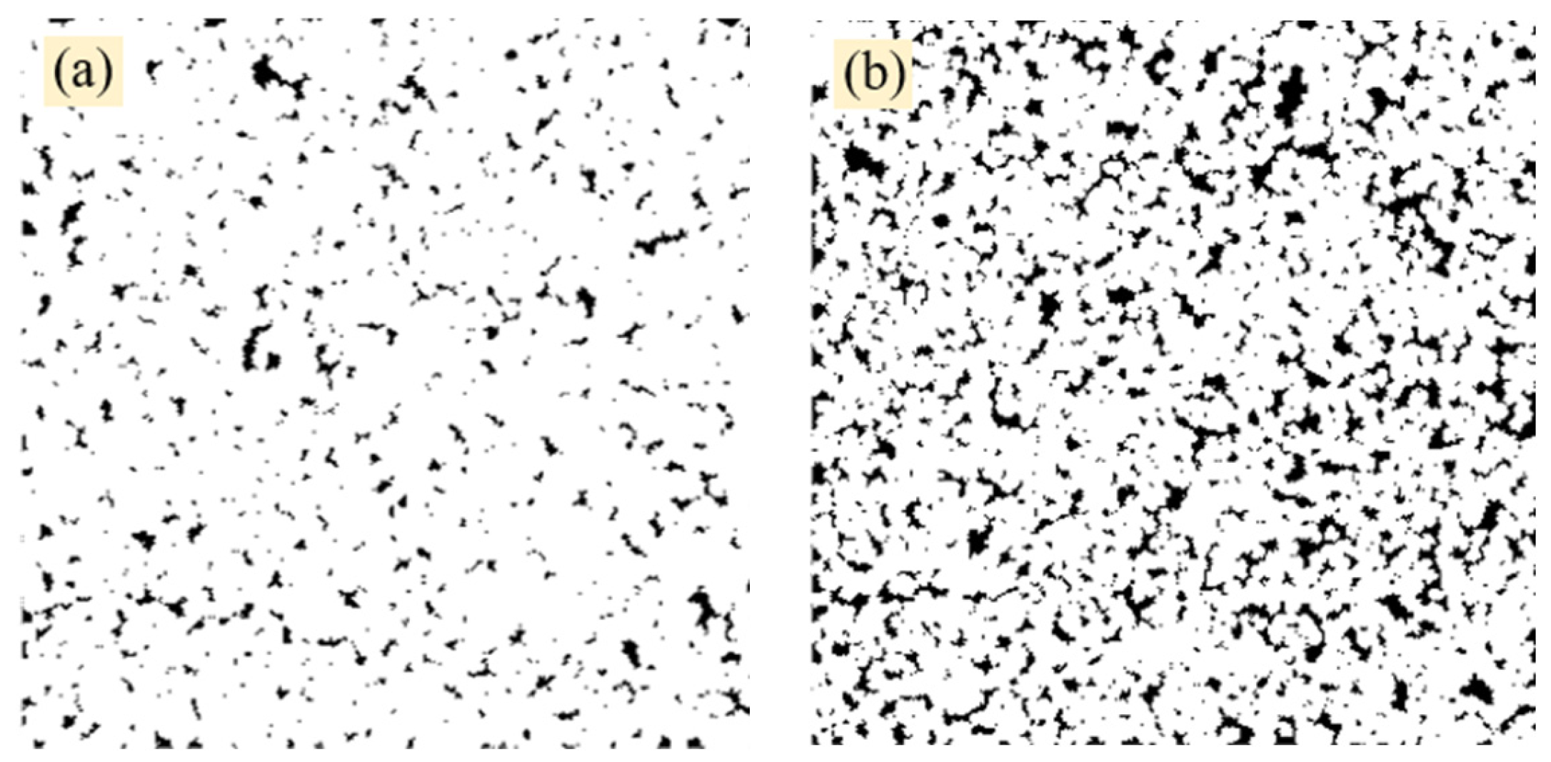
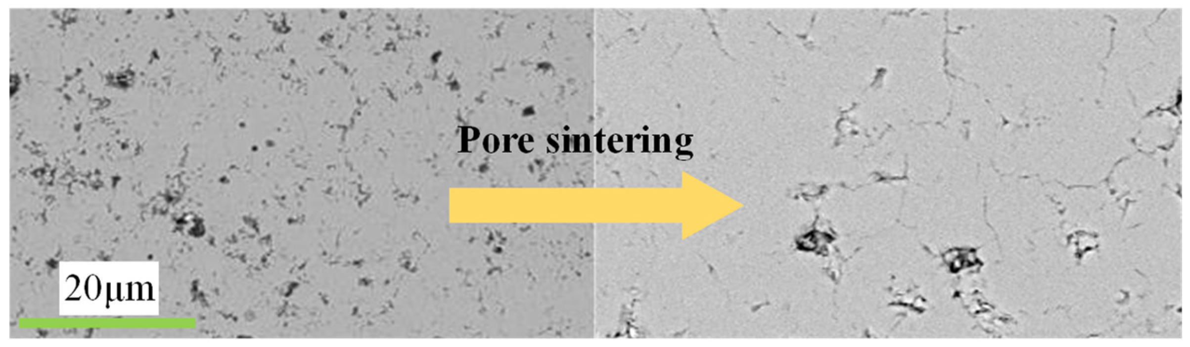
3.1. Thermal-Barrier-Coating Porosity Statistics

The cross-sectional microstructural properties of the heat barrier coating were observed using SEM and optical microscopy, as illustrated in Figure 2. The porosity of the thermal barrier coating was determined by ImageJ software analysis, and the porosity of the thermal barrier coating with a coarse initial YSZ particle size was 28.4% ± 5.1%, whereas the porosity of the thermal barrier coating with a fine initial particle size was 18.2% ± 3.4%. It was widely known that the spray-prepared thermal barrier coating had an increased porosity when the starting particle size was bigger. Following the thermal shock test of the spray-applied thermal barrier coating, the YSZ powder that was not entirely sintered during spraying is further sintered, and the porosity of the thermal barrier coating is further reduced, as illustrated in Figure 6. However, the porosity would not continue to decrease, and the porosity would gravitate to a constant value after around 100 tests. The porosity of the thermal barrier coating was stable between 9% and 21% after high-temperature exposures. The porosity in the simulation model was set to 5%, 10%, 15%, 20%, and 25% to assist with computation and analysis. Although the porosity of the thermal barrier coating decreased and finally stabilized within a particular range throughout the thermal shock test, cracks occur as the porosity reduces. Therefore, the cracks were replaced by flattened holes in the subsequent modeling to better reflect the real situation.

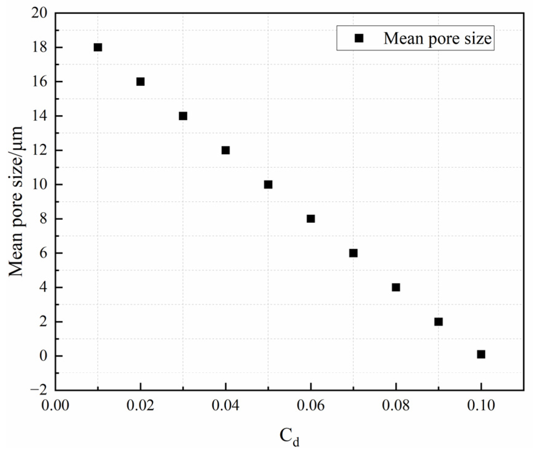
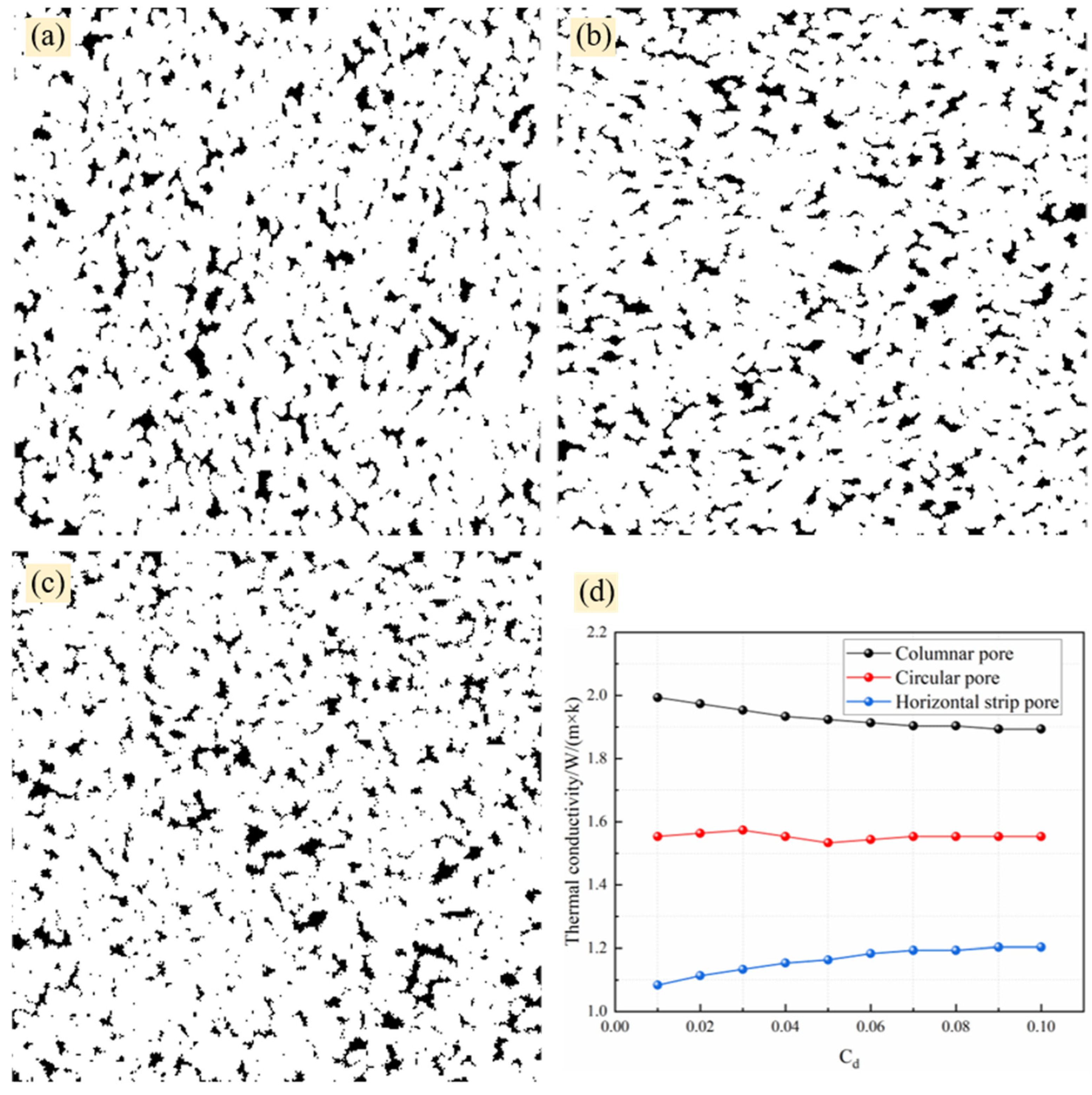
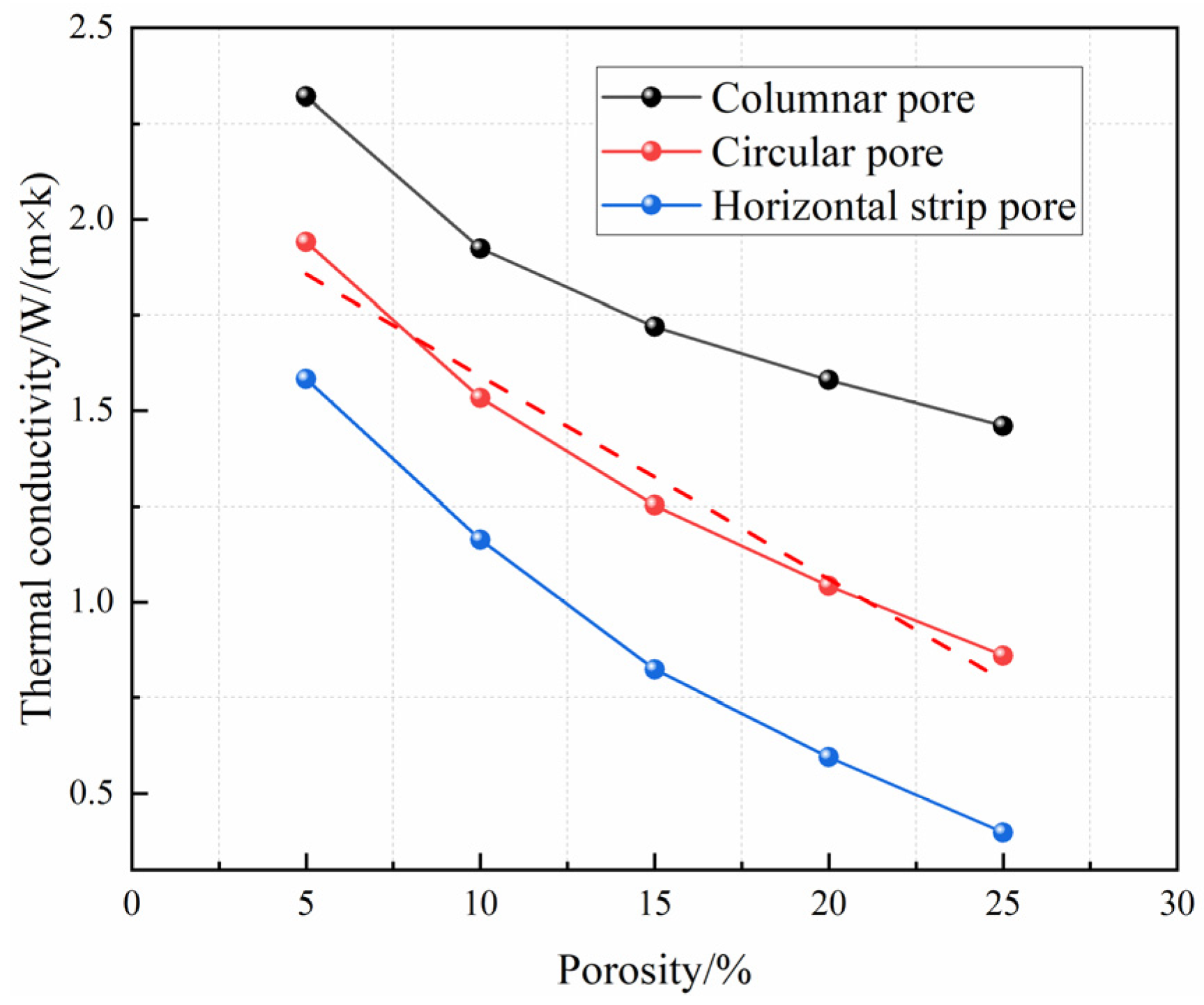
3.2. Effect of Pores on Thermal Conductivity

The model with three typical features was generated while constructing the simulation model of thermal barrier coating by modifying the model parameters. The average size of the pores may be estimated from Figure 3 to be between 0.1 and 15 μm, and the pore size could be modified by adjusting the value of the growth core distribution probability, cd, in the QSGS algorithm. Figure 7 depicts the fluctuation of the average pore size with the cd value, using 10% porosity as an example. Figure 6 clearly shows that the average size of the holes in the model decreased with the rising cd value, indicating a linear connection. As a result, while analyzing the influence of the average pore size on the thermal conductivity of thermal barrier coatings, the cd value could be substituted for the average pore size. The difference in the heat conductivity of coatings with different microstructural characteristics, with the cd value at 10% porosity, is shown in Figure 8.
Figure 8 shows that regardless of the cd value, the thermal conductivity of the columnar pores was larger than that of the strip and globular pores, and the thermal conductivity of the globular pores was always greater than that of the strip pores. This means that when the pores in the thermal barrier coating were vertical columns, the heat conduction was enhanced, so the production of pores of this shape must be controlled. When the pores had a horizontal strip form, the heat transmission was inhibited, which was particularly beneficial to increasing the service temperature of the thermal barrier coating. As a result, future research should concentrate on how to modify the spraying process to adjust the form and percentage of the pores. When the shape of the pores was mostly globular, the heat conductivity did not greatly change as the cd value changes. This is because the globular pores were isotropic, and when the size of the pores was stabilized within a certain range, its microstructure characteristics would not greatly fluctuate, resulting in a small difference in the transmission path of the heat flow under this structure: the average size of the pores at this time did not affect the thermal conductivity of the coating when the average size of the pores changed. When the average pore size of the columnar pores grew (cd value lowers), the thermal barrier coating’s thermal conductivity tended to increase. The decrease in the cd value indicated that the core of the pore growth was reducing, and more growth iterations were required to achieve the same porosity, resulting in a decrease in the number of pores but an increase in the average size as well as an increase in the anisotropy of the columnar pores and a reduction in fluid obstruction, which was the reason for the increase in thermal conductivity. However, when the cd value reached 0.05~0.06, the heat conductivity of the thermal barrier coating tended to be steady as the cd value increased. The thermal conductivity law of the horizontal strip pores was diametrically opposed to that of the vertical columnar pores. An enhancement in the average size of the horizontal strip pores increased anisotropy, which increased the heat flow blockage by the pores, resulting in a slower thermal transfer and a decrease in thermal conductivity. In addition to the size of the pores having an effect on the thermal barrier coating’s heat transfer, the different percentage of the pores would change its thermal conductivity, which was one of the reasons for the thermal barrier coating failing after a certain period of service. Thermal insulating coatings with porosities ranging from 5% to 25% were explored in this research, and Figure 9 demonstrates the thermal conductivity curves of coatings with varying pore characteristics as a function of the porosity, with a cd value of 0.05.
When the porosity was the same, it could be observed that the thermal conductivity of the columnar pores was always larger than that of the globular and horizontal strip pores, and the thermal conductivity of the globular pores was always more than that of the horizontal strip pores. This means that vertical pores accelerate heat transfer, spherical ones are in the center, and horizontal pores are the slowest. Meanwhile, regardless of the pore structure, the heat conductivity of the coating diminished as the porosity increased. The space filled by non-solids inside the coating rose as the porosity increased. Since the rate of heat transmission in solids was significantly faster than in gases, the total thermal conductivity of the coating decreased. However, the porosity should not be continuously raised since an excessive porosity reduced the coating’s strength, rendering it unable to match the demands of the application. Furthermore, Figure 8 shows that when the pores in the thermal barrier coating were globular, the thermal conductivity linearly varied with the porosity (linear fit is higher than 96%), and the thermal conductivity decreased with an increasing porosity. Since the isotropy of globular holes did not considerably vary as the porosity rose, the drop in heat conductivity was primarily attributable to an increase in the fraction of isotropic pores.

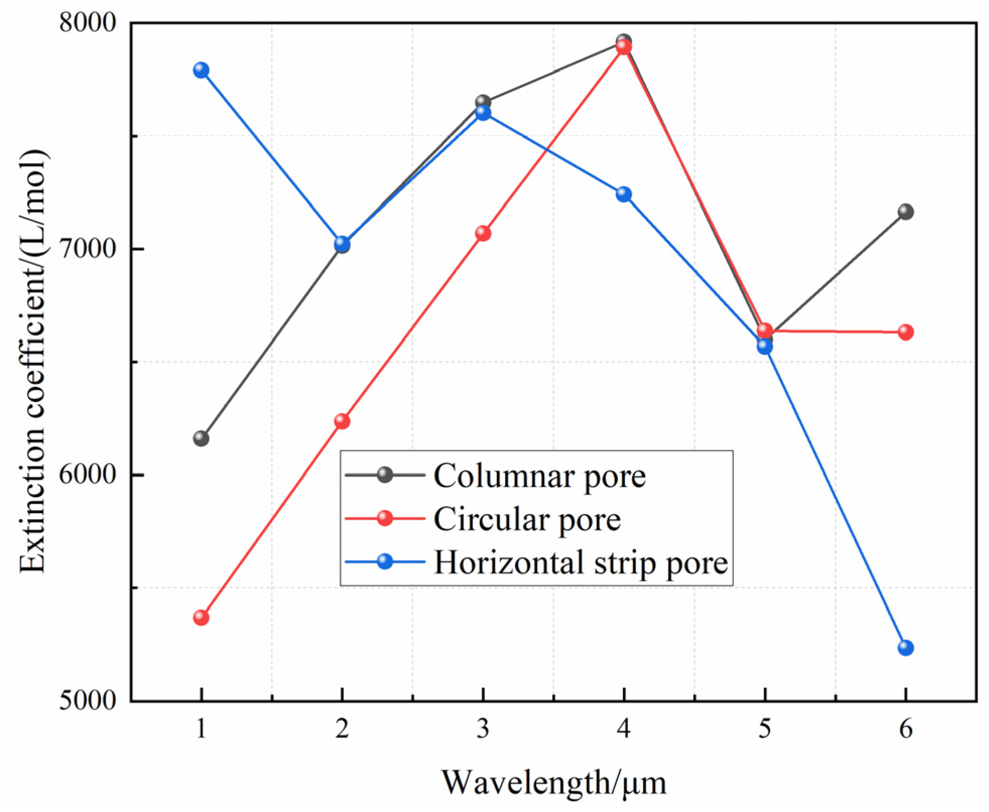
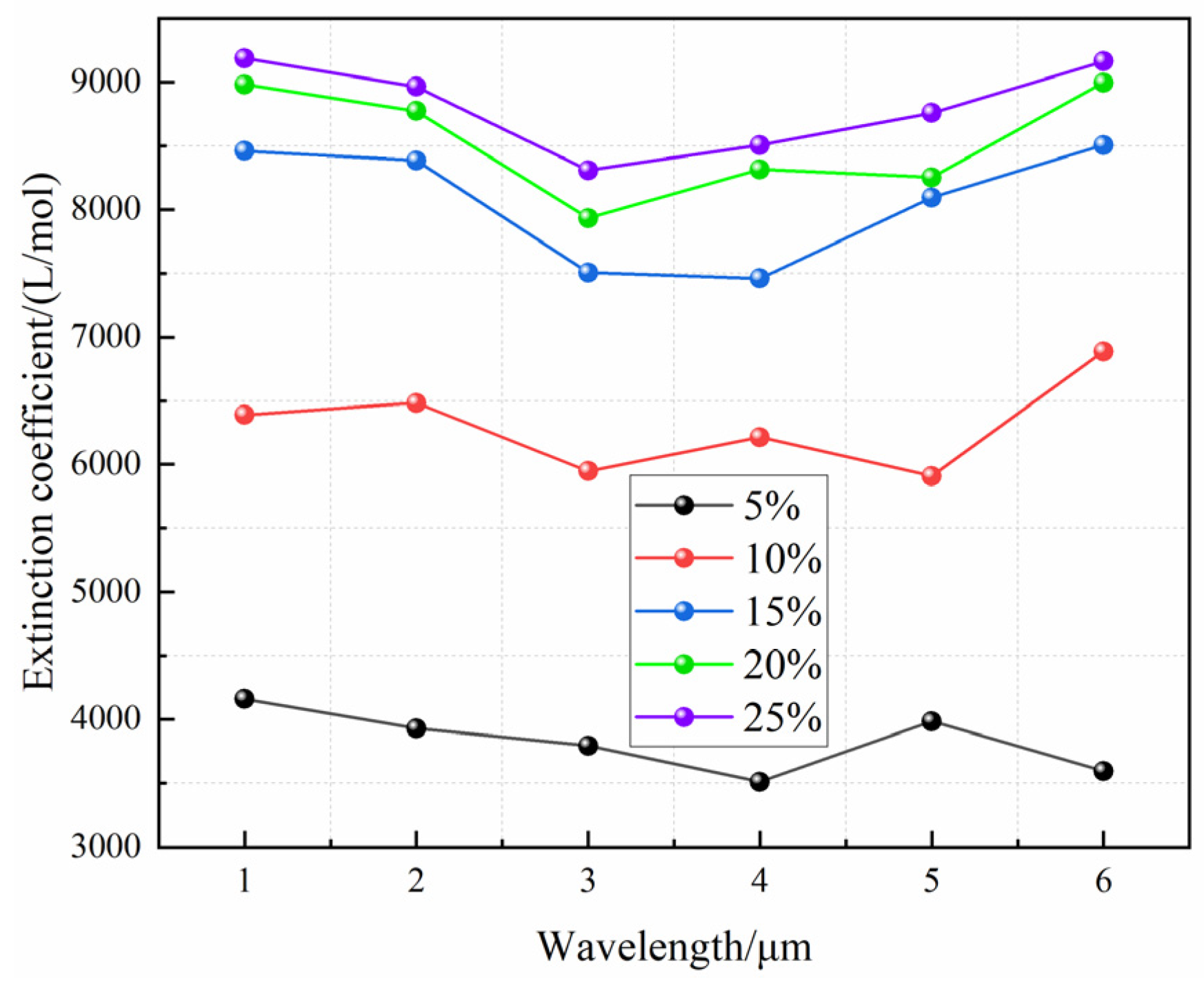
3.3. Effect of Pores on Thermal Radiation

YSZ materials’ optical characteristics have long been investigated [26]. The findings demonstrated that the absorption coefficient of YSZ materials was very low in the wavelength range of 0.4–6 μm, implying that it did not absorb waves in the estimated wavelength range. Therefore, the absorption of thermal radiation was not considered in this paper. This paper focused on the the influence of the porosity, pore size, and shape on the thermal radiation properties. Meanwhile, the ultimate reflectance would be affected by the difference in surface roughness. In this paper, rough surfaces were produced at random using the Monte Carlo approach, and then waves of various wavelengths were emitted from various angles to mimic reflectivity. In the meantime, the FDTD approach could properly solve Maxwell’s equations, and, in this research, the numerical solution was employed as the reference object of the simulation results, with a comparison given in Figure 10.
Figure 10 shows that when the incidence angles were 0°, 30°, and 45°, the simulation results were closer to the estimated values, demonstrating that the model might be used to determine the reflectance of coatings with diverse microstructural characteristics. When the incidence angle was 60°, however, the gap between the simulated value and the numerical solution was significant. This was due to the angle of incidence at this point being too great, while the roughness of the coated surface was very tiny, which was beyond the model’s range of application. In conclusion, the model for simulating and calculating coating reflectivity could be applied to scenarios with a small angle of incidence or a high degree of roughness and a large angle of incidence, and future research should focus on the model’s application limits and the modification of the model’s algorithm to broaden its application scope. Following the determination of the surface reflections, the influence of changes in the microstructural features on the thermal radiation characteristics is investigated by modeling the extinction coefficients following a wave incidence. The thermal barrier coatings with three typical characteristics were independently simulated, and the variations in the extinction coefficients are depicted in Figure 11.
Figure 11 clearly shows that the form of the pores had no significant influence on the extinction coefficient. The extinction coefficient of the horizontal strip-shaped holes diminished as the wavelength increased. This implies that when the temperature rose (the wavelength falls), the extinction coefficient rose, making it more likely to obstruct the radiation, hence increasing the service temperature of the thermal barrier coating. In contrast, globular and columnar pores tended to lower the coating’s service temperature. As a result, in terms of the thermal conductivity and extinction coefficient at high-temperature exposures, the proportion of columnar holes must be reduced while the percentage of horizontal strip pores must be increased. In this paper, by adjusting the spraying process parameters to adjust the porosity, it was realized that coatings with different microstructural characteristics and porosities can be obtained by changing parameters such as the spraying power, spraying angle, and speed. However, it is still difficult to grasp the microstructure as well as the quantitative control of the porosity, which is one of the ongoing works. Second, the porosity was a typical characteristic of the coating microstructure, and Figure 12 depicts the fluctuation of the coating’s extinction coefficient under different porosities. When simulating the influence of the porosity in this research, only globular pores were chosen to simplify the analysis.
As can be seen from Figure 12, when the incident wavelength was the same, the extinction coefficient increased with an enhancing porosity, and the rate of increase became slower and slower. The difference in the extinction coefficient of the thermal barrier coatings was not significant when the porosity was increased to greater than 15%, indicating that increasing the porosity could only enhance the thermodynamic performance to a limited amount. In terms of numbers, increasing the coating porosity from 5% to 10% improved the extinction coefficient by a factor of around 1.6. When the porosity was increased to 15%, the extinction coefficient increased by a factor of around 2.4. When the porosity was increased to 20%, the extinction coefficient increased by a factor of around 2.5. At this point, the extinction coefficient of the coating showed no discernible difference from that of the coating with 15% porosity, indicating that increasing the porosity to a certain amount can impede radiant energy transmission.

4. Conclusions

Thermal barrier coatings with various porosities were produced using the APS approach and submitted to thermal shock testing in this paper. SEM and optical microscopy were used to assess the porosity of the coatings. It was found that variable starting particle sizes and variable periods of high-temperature exposure resulted in coatings with varying porosities. It was mainly manifested that the finer the initial powder particle size is, the lower the porosity of the coating is. The coating’s porosity reduced as it was exposed to high temperatures over an extended period of time. However, the porosity would settle after a specific amount of time. Before the number of thermal shock tests reached about 100, the porosity would decrease with the increase in the number of tests, and, when it reached this range, the porosity basically tended to stabilize, while the stabilized range was between 9% and 21%. Secondly, following the thermal shock test, the roughness of the coated surface varied from Rz0.1 to Rz6.3. Compared with previous studies [27], the anisotropy of the microstructure inside the thermal barrier coating was considered in the modeling of this paper, which makes the simulated results closer to the actual values. While the effects of microstructural features on the heat transfer of thermal barrier coatings were studied more from a macroscopic point of view in previous studies [28,29,30], this paper considered the effects of microstructural features on the thermal conductivity and radiation properties of the coatings after high-temperature exposure. The work in this paper further complemented the heat transfer modeling of thermal barrier coatings at different temperatures, which is an important reference for improving the service performance of thermal barrier coatings. In addition, it helped to further reveal the micro-mechanism of the effect of the microstructure of the thermal barrier coating on its radiation characteristics, which can lay the foundation for the subsequent study of the changes in microstructural features caused by the phase transformation of the thermal-barrier-coating material after high-temperature exposure.
The impacts of coating microstructural characteristics on heat conductivity and radiation were investigated using numerical computation and simulation based on the data presented above. The results demonstrated that at high temperatures, columnar holes promoted heat conduction and radiation, whereas horizontal strips functioned as an impediment. When the porosity increased, the thermal conductivity of the coating dropped about linearly, indicating that the thermal conductivity would be hampered relatively evenly. Furthermore, if the angle of incidence of the heat radiation was too great in coatings with a relatively low roughness, the reflectance derived from the simulation would need to be rectified. Finally, the extinction coefficient increased with an increasing porosity, albeit at a slower pace, indicating that the increasing porosity might only inhibit the heat radiation to a limited amount. When the porosity exceeded 15%, the coating’s thermal radiation performance slowly improved. All of the foregoing results showed that adjusting the microstructure of the coating to achieve a reasonable structure would raise the service temperature and extend the coating’s service life. Therefore, future studies should begin with tests to quantitatively assess the development law of the microstructure under various experimental situations. This paper combined the methods of experiment and simulation to obtain the relevant laws first and then used the experiment to verify them. In this paper, the porosity was regulated by setting different spraying powers in order to make the coating have better heat radiation properties. Secondly, the shape of the porosity was regulated by adjusting the parameters such as the angle and speed of spraying. However, this study still belonged to the trial-and-error stage, and there was no systematic process-parameter-selection system, which was also the content of this ongoing work. The purpose of this paper was to guide the experiments through the method of simulation, to control the direction of the experiments being carried out and provide a theoretical basis and guidance for the experiments. Furthermore, the research approach in this work, which combines simulation and numerical computation, offered broad application possibilities and benefits for the research and development of novel materials as well as cost savings.

Author Contributions

Conceptualization, Z.X., Q.Z. and D.Y.; methodology, Z.X. and D.Y.; software, Z.X. and D.Y.; validation, S.X., Q.Z. and J.X.; formal analysis, Z.X., S.X. and D.Y.; investigation, Z.X., S.X., Q.Z., J.X. and D.Y.; resources, Z.X., Q.Z. and D.Y.; data curation, Z.X., S.X. and J.X.; writing—original draft preparation, Z.X. and D.Y.; writing—review and editing, S.X., Q.Z. and J.X.; visualization, Z.X., S.X., Q.Z., J.X. and D.Y.; supervision, Z.X., Q.Z. and D.Y.; project administration, Q.Z., J.X. and D.Y.; funding acquisition, Z.X., J.X. and D.Y. All authors have read and agreed to the published version of the manuscript.

Funding

This research was funded by the National Natural Science Foundation of China (no. 52205547 to D.Y.), the Science and Technology Plan Project of Wuhu City (no. 2022yf67 to Z.X.), the Natural Science Research Project of the Wuhu Institute of Technology (no. wzyzr202331 to Z.X.), the Key Research and Development Projects in Anhui Province (no. 2022a05020004 to D.Y.), the Open Research Fund of the Fujian Provincial Key Laboratory of Terahertz Functional Devices and Intelligent Sensing, Fuzhou University (no. FPKLTFDIS202301 to D.Y.), the 2023 Anhui Province Scientific Research Preparation Plan Project (no. 2023AH052399 to Z.X.), the Open Research Fund of the Anhui Key Laboratory of Detection Technology and Energy Saving Devices (no. JCKJ2022A08 to D.Y.), the Anhui Institute of Future Technology Enterprise Cooperation Project (no. 2023qyhz04 to D.Y.), and the Scientific Research Project of Wanjiang College, Anhui Normal University (no. WJKY-202302 to J.X.).

Institutional Review Board Statement

Not applicable.

Informed Consent Statement

Not applicable.

Data Availability Statement

Not applicable.

Conflicts of Interest

The authors declare no conflict of interest.

References

  1. Wang, T.; Xuan, Y.; Han, X. Investigation on hybrid thermal features of aero-engines from combustor to turbine. Int. J. Heat Mass Transf. 2023, 200, 123559. [Google Scholar] [CrossRef]
  2. Ezugwu, E.O.; Bonney, J.; Yamane, Y. An overview of the machinability of aeroengine alloys. J. Mater. Process. Technol. 2003, 134, 233–253. [Google Scholar] [CrossRef]
  3. Liu, Y.; Xu, G.; Fu, Y.; Wen, J.; Huang, H. Thermal dynamic and failure research on an air-fuel heat exchanger for aero-engine cooling. Case Stud. Therm. Eng. 2023, 42, 102715. [Google Scholar] [CrossRef]
  4. Vaßen, R.; Bakan, E.; Mack, D.E.; Guillon, O. A perspective on thermally sprayed thermal barrier coatings: Current status and trends. J. Therm. Spray Technol. 2022, 31, 685–698. [Google Scholar] [CrossRef]
  5. Dong, W.; Zhu, J.; Zhou, Z.; Chi, X. Heat transfer and temperature analysis of an aeroengine strut under icing conditions. J. Aircr. 2015, 52, 216–225. [Google Scholar] [CrossRef]
  6. Zhang, G.; Zhu, R.; Xie, G.; Li, S.; Sundén, B. Optimization of cooling structures in gas turbines: A review. Chin. J. Aeronaut. 2022, 35, 18–46. [Google Scholar] [CrossRef]
  7. Unnikrishnan, U.; Yang, V. A review of cooling technologies for high temperature rotating components in gas turbine. Propuls. Power Res. 2022, 11, 293–310. [Google Scholar] [CrossRef]
  8. Cao, X.Q.; Vassen, R.; Stöver, D. Ceramic materials for thermal barrier coatings. J. Eur. Ceram. Soc. 2004, 24, 1–10. [Google Scholar] [CrossRef]
  9. Padture, N.P.; Gell, M.; Jordan, E.H. Thermal Barrier Coatings for Gas-Turbine Engine Applications. Science 2002, 296, 280–284. [Google Scholar] [CrossRef]
  10. Vagge, S.T.; Ghogare, S. Thermal barrier coatings: Review. Mater. Today Proc. 2022, 56, 1201–1216. [Google Scholar] [CrossRef]
  11. Tano, I.; Nylen, P.; Wigren, J.; Gupta, M.K.; Curry, N. Relationships Between Coating Microstructure and Thermal Conductivity in Thermal Barrier Coatings—A Modelling Approach. In Thermal Spray 2010: Global Solutions for Future Applications; Springer: Berlin/Heidelberg, Germany, 2010; pp. 66–72. [Google Scholar]
  12. Fang, H.; Wang, W.; Yang, Z. Phase stability, thermal shock behavior and CMAS corrosion resistance of Yb2O3-Y2O3 co-stabilized zirconia thermal barrier coatings prepared by atmospheric plasma spraying. Surf. Coat. Technol. 2021, 427, 127864. [Google Scholar] [CrossRef]
  13. Ye, D.; Xu, Z.; Pan, J. Prediction and Analysis of the Grit Blasting Process on the Corrosion Resistance of Thermal Spray Coatings Using a Hybrid Artificial Neural Network. Coatings 2021, 11, 1274. [Google Scholar] [CrossRef]
  14. Ye, D.; Wang, W.; Zhou, H. Quantitative determination of porosity in thermal barrier coatings using terahertz reflectance spectrum: Case study of atmospheric-plasma-sprayed YSZ coatings. IEEE Trans. Terahertz Sci. Technol. 2020, 10, 383–390. [Google Scholar] [CrossRef]
  15. Ye, D.; Wang, W.; Zhou, H. In-situ evaluation of porosity in thermal barrier coatings based on the broadening of terahertz time-domain pulses: Simulation and experimental investigations. Opt. Express 2019, 27, 28150–28165. [Google Scholar] [CrossRef]
  16. Li, R.; Ye, D.; Xu, Z. Nondestructive evaluation of thermal barrier coatings thickness using terahertz Time-Domain spectroscopy combined with hybrid machine learning approaches. Coatings 2022, 12, 1875. [Google Scholar] [CrossRef]
  17. Chi, W.; Sampath, S.; Wang, H. Microstructure-thermal conductivity relationships for plasma-sprayed yttria-stabilized zirconia coatings. J. Am. Ceram. Soc. 2008, 91, 2636–2645. [Google Scholar] [CrossRef]
  18. Golosnoy, I.O.; Tsipas, S.A.; Clyne, T.W. An analytical model for simulation of heat flow in plasma-sprayed thermal barrier coatings. J. Therm. Spray Technol. 2005, 14, 205–214. [Google Scholar] [CrossRef]
  19. Wang, L.; Wang, Y.; Sun, X.G.; He, J.Q.; Pan, Z.Y.; Zhou, Y.; Wu, P.L. Influence of pores on the thermal insulation behavior of thermal barrier coatings prepared by atmospheric plasma spray. Mater. Des. 2011, 32, 36–47. [Google Scholar] [CrossRef]
  20. Cernuschi, F.; Ahmaniemi, S.; Vuoristo, P.; Mäntylä, T. Modelling of thermal conductivity of porous materials: Application to thick thermal barrier coatings. J. Eur. Ceram. Soc. 2004, 24, 2657–2667. [Google Scholar] [CrossRef]
  21. Cernuschi, F.; Bison, P.; Moscatelli, A. Microstructural characterization of porous thermal barrier coatings by laser flash technique. Acta Mater. 2009, 57, 3460–3471. [Google Scholar] [CrossRef]
  22. Wang, M.; Wang, J.; Pan, N.; Chen, S. Mesoscopic predictions of the effective thermal conductivity for microscale random porous media. Phys. Rev. E 2007, 75, 036702. [Google Scholar] [CrossRef] [PubMed]
  23. Gupta, N.; Chaitanya, G.R.; Mishra, S.C. Lattice Boltzmann method applied to variable thermal conductivity conduction and radiation problems. J. Thermophys. Heat Transf. 2006, 20, 895–902. [Google Scholar] [CrossRef]
  24. Yee, K. Numerical solution of initial boundary value problems involving Maxwell’s equations in isotropic media. IEEE Trans. Antennas Propag. 1966, 14, 302–307. [Google Scholar]
  25. Sullivan, D.M. Electromagnetic Simulation Using the FDTD Method; John Wiley & Sons: Piscataway, NJ, USA, 2013. [Google Scholar]
  26. Manara, J.; Arduini-Schuster, M.; Rätzer-Scheibe, H.J. Infrared-optical properties and heat transfer coefficients of semitransparent thermal barrier coatings. Surf. Coat. Technol. 2009, 203, 1059–1068. [Google Scholar] [CrossRef]
  27. Lu, Z.; Myoung, S.W.; Kim, H.S.; Kim, M.S.; Lee, J.H.; Jung, Y.G.; Jang, J.C.; Paik, U. Microstructure Evolution and Interface Stability of Thermal Barrier Coatings with Vertical Type Cracks in Cyclic Thermal Exposure. J. Therm. Spray Technol. 2013, 22, 671–679. [Google Scholar] [CrossRef]
  28. Ganvir, A.; Kumara, C.; Gupta, M.; Nylen, P. Thermal Conductivity in Suspension Sprayed Thermal Barrier Coatings: Modeling and Experiments. J. Therm. Spray Technol. 2017, 26, 71–82. [Google Scholar] [CrossRef]
  29. Shi, H.; Zhao, C.Y.; Wang, B.X. Modeling the thermal radiation properties of thermal barrier coatings based on a random generation algorithm. Ceram. Int. 2016, 42, 9752–9761. [Google Scholar] [CrossRef]
  30. Zhang, B.J.; Wang, B.X.; Zhao, C.Y. Microstructural effect on the radiative properties of YSZ thermal barrier coatings (TBCs). Int. J. Heat Mass Transf. 2014, 73, 59–66. [Google Scholar] [CrossRef]
Figure 1. Schematic structure of thermal barrier coating: red: Top coat.
Coatings 13 01675 g001
Figure 2. Pictures of sample: (a) after spraying; (b) after thermal shock test; (c) cross-section microstructure after thermal shock test.
Coatings 13 01675 g002
Figure 3. Internal microstructure of the thermal barrier coating: (a) coarse grain size; (b) fine grain size.
Coatings 13 01675 g003
Figure 4. Surface morphology of thermal barrier coatings.
Coatings 13 01675 g004
Figure 5. Modeling of porous media with different structural parameters: (a) 5% porosity; (b) 15% porosity.
Coatings 13 01675 g005
Figure 6. Microstructural changes in thermal barrier coatings after thermal shock test.
Coatings 13 01675 g006
Figure 7. Plot of the variation pattern of average pore size with cd value.
Coatings 13 01675 g007
Figure 8. Plot of the variation pattern of thermal conductivity with cd value for different pore characteristics: (a) columnar pore; (b) horizontal strip pore; (c) globular pore; (d) heat conductivity coefficient.
Coatings 13 01675 g008
Figure 9. Plot of thermal conductivity versus porosity for different pore characteristics.
Coatings 13 01675 g009
Figure 10. Comparison of the effect of different angles of incidence on the reflectance of coatings on randomly rough surfaces: (a) 0°; (b) 30°; (c) 45°; (d) 60°.
Coatings 13 01675 g010
Figure 11. Variations in extinction coefficients with incident wavelengths for different pore characteristics.
Coatings 13 01675 g011
Figure 12. Variations in extinction coefficients with incident wavelengths for different porosities.
Coatings 13 01675 g012
Table 1. Spraying process parameters of APS method.
Spraying ParameterBonding CoatYSZ Ceramic Coat
Power of spray gun, KW3036–40
Flow rate of main gas, L/min3535
Flow rate of minor gas, L/min99
Speed of powder feeder, g/min1824
Spraying distance, mm10080
Temperature of substrate, °C250–300/
Disclaimer/Publisher’s Note: The statements, opinions and data contained in all publications are solely those of the individual author(s) and contributor(s) and not of MDPI and/or the editor(s). MDPI and/or the editor(s) disclaim responsibility for any injury to people or property resulting from any ideas, methods, instructions or products referred to in the content.

