.jpg)
CMAS Corrosion Behavior of Nanostructured YSZ and Gd-Yb-Y-Stabilized Zirconia Coatings


Abstract
:1. Introduction
2. Materials and Methods
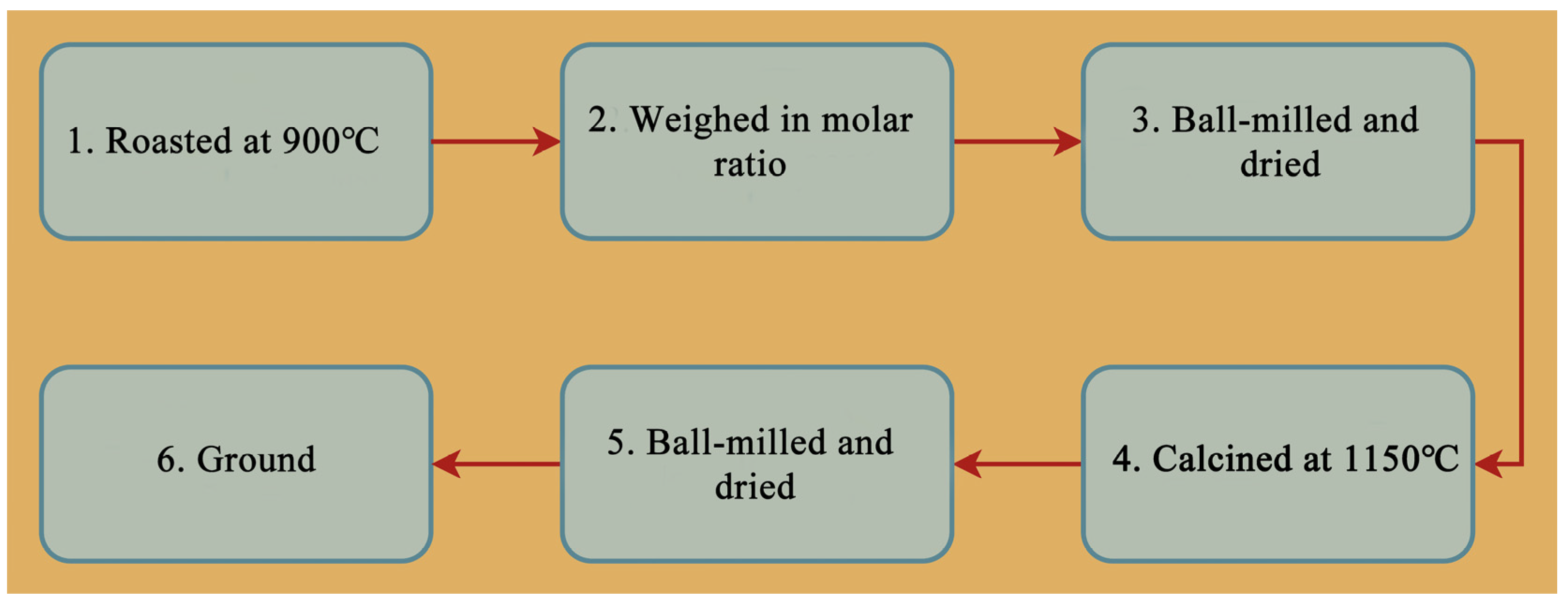
2.1. Preparation of CMAS Powder
2.2. Preparation of Coatings
2.3. CMAS Corrosion Experiments
2.4. Characterization
3. Results
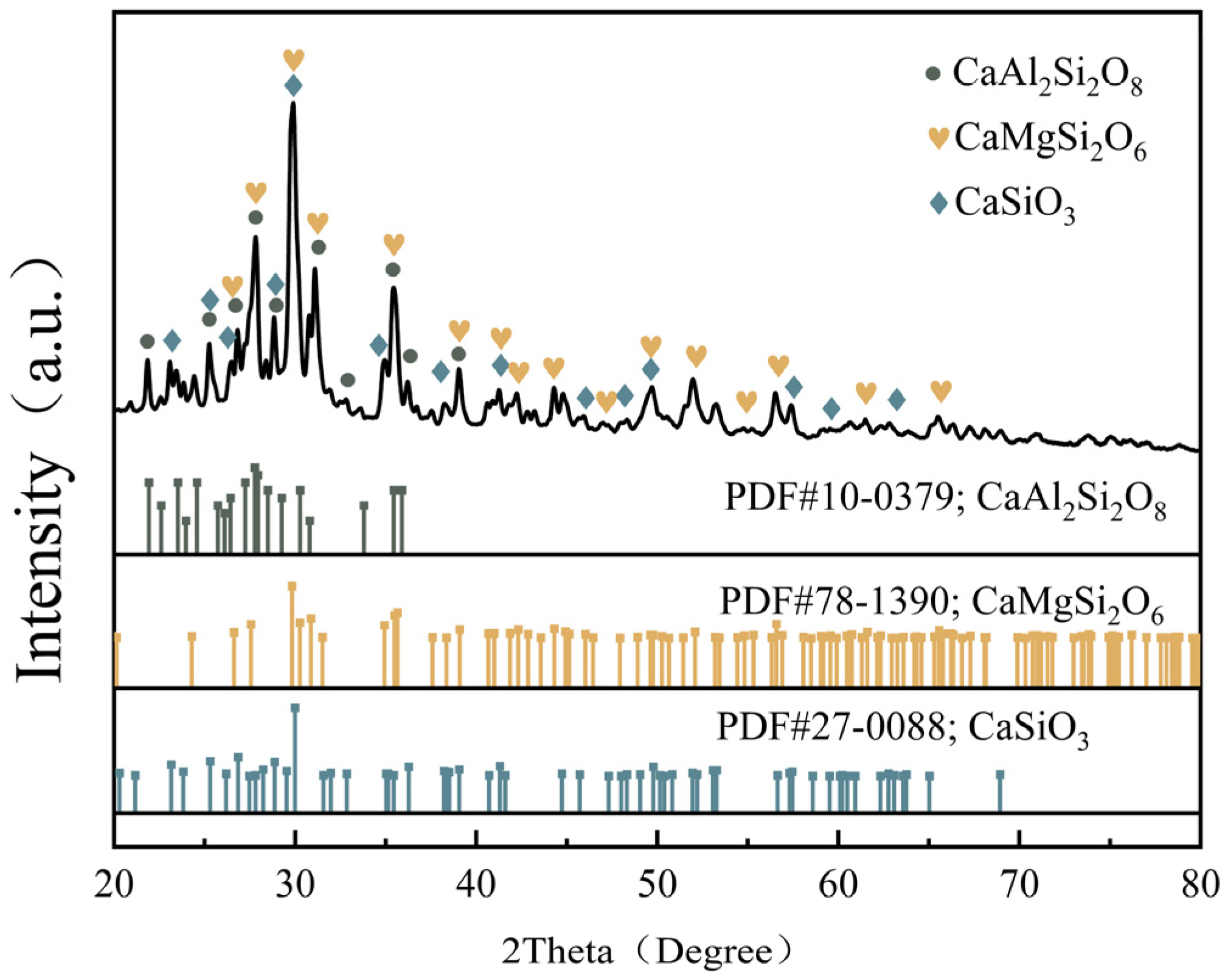
3.1. CMAS Powder
3.2. Coatings before and after CMAS Corrosion
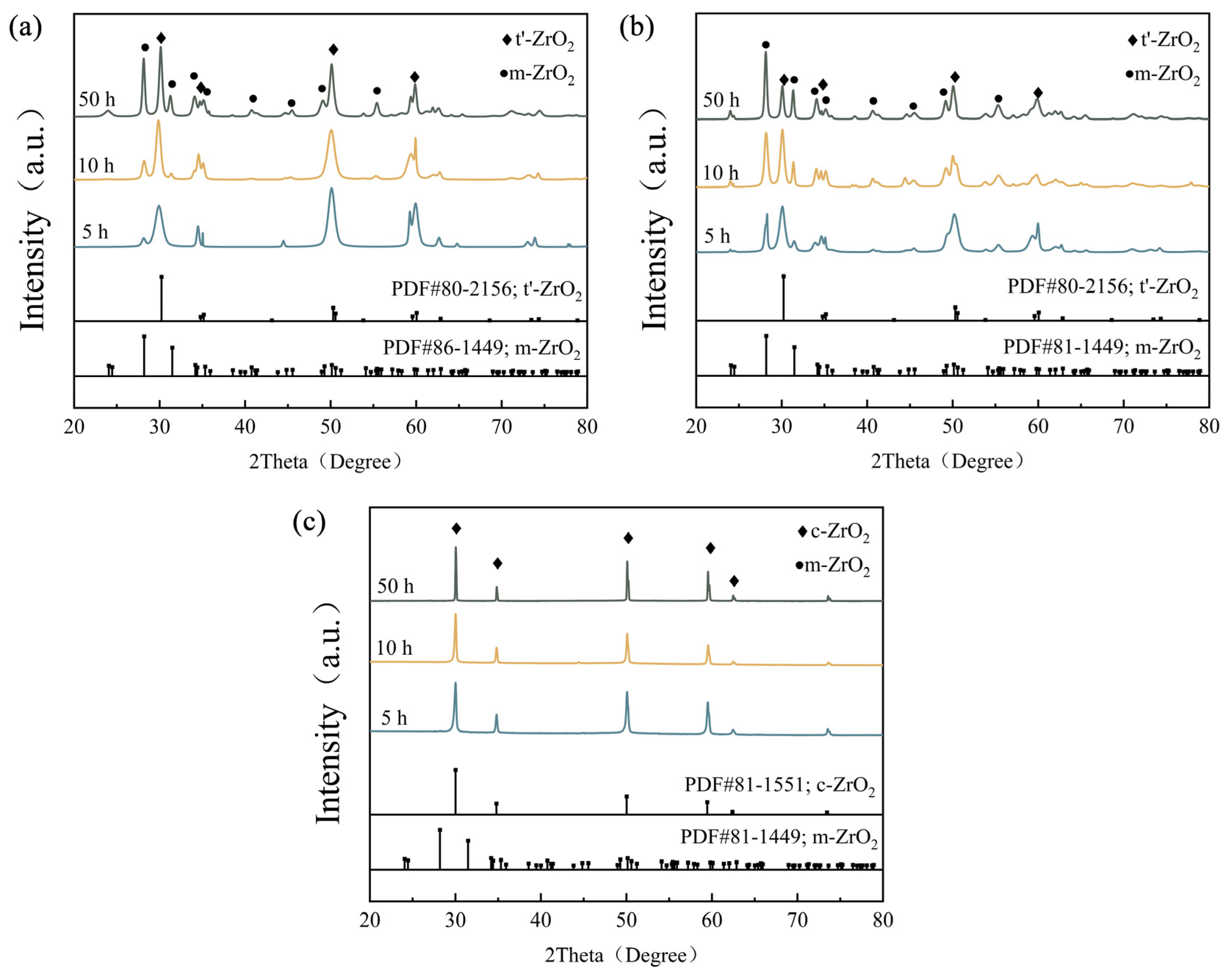
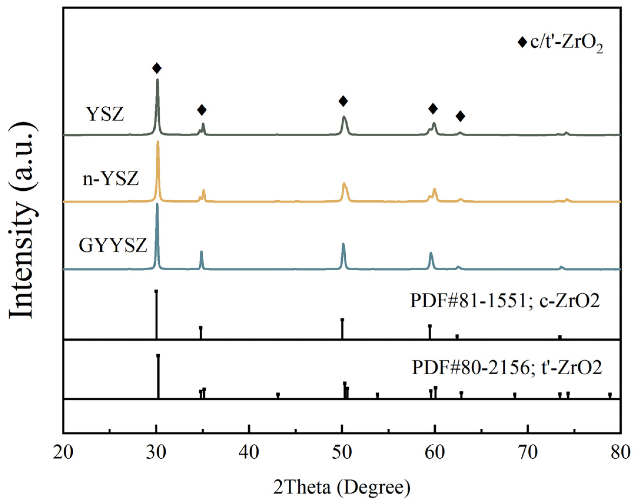
3.2.1. Phase Composition
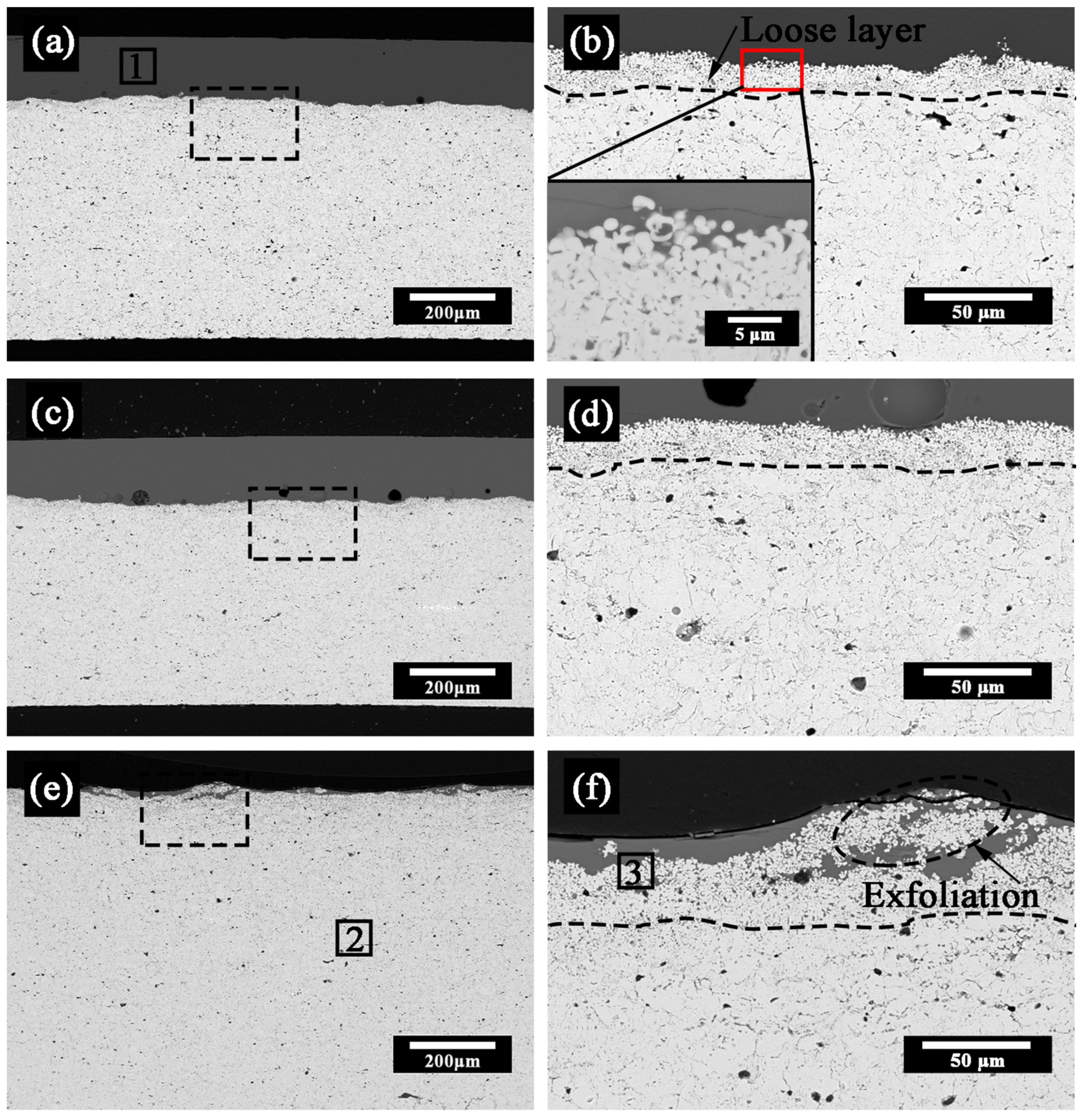
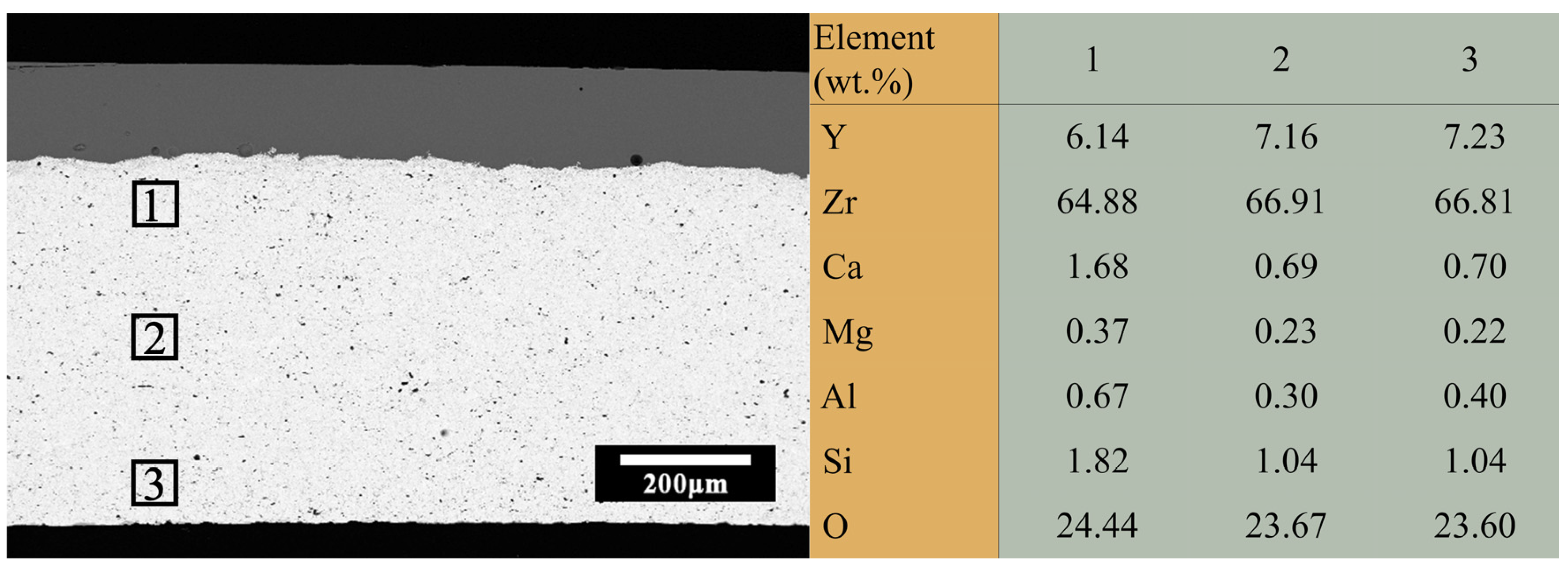
3.2.2. Microstructure and Chemical Composition
3.2.3. Microhardness
4. Discussion
4.1. Penetration Depth
4.2. Coatings Densification
4.3. Phase Transition and Spheroidization
4.4. Corrosion Mechanisms
5. Conclusions
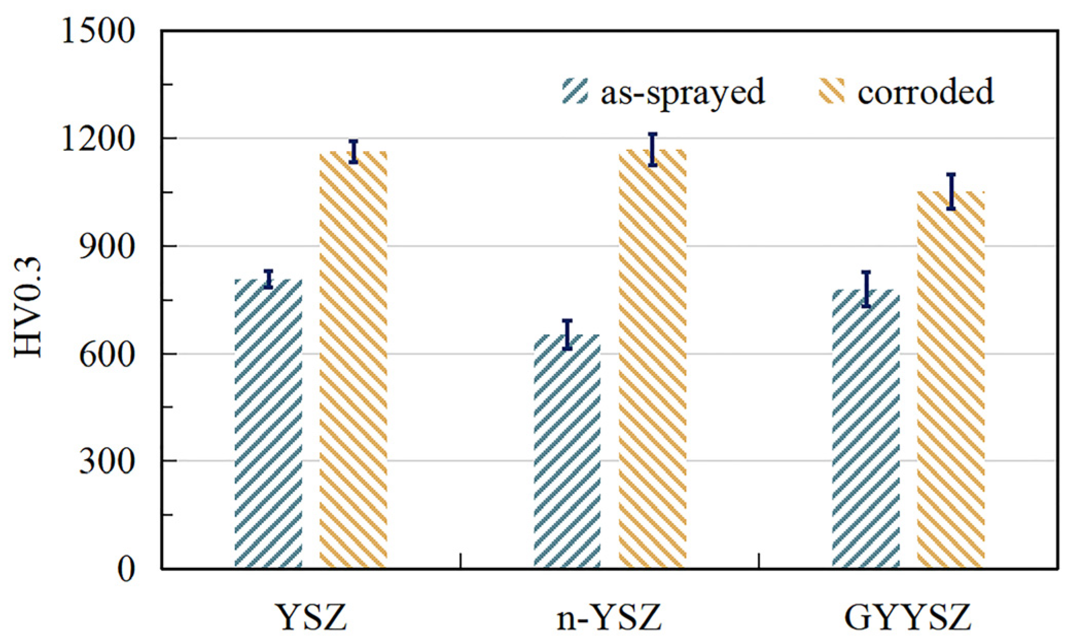
- Decreased porosity and increased microhardness are found in all three coatings after CMAS corrosion. The increase in microhardness of n-YSZ coatings is more pronounced than that of YSZ coatings, while that of GYYSZ coatings is relatively small.
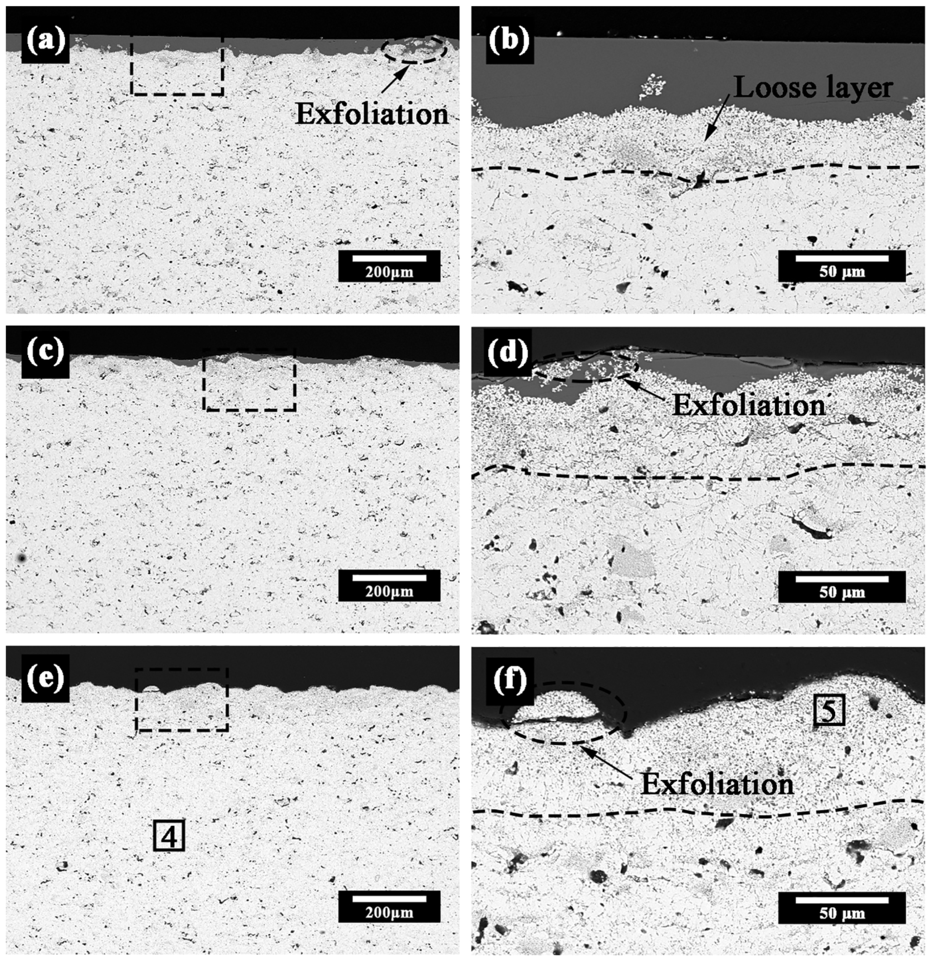
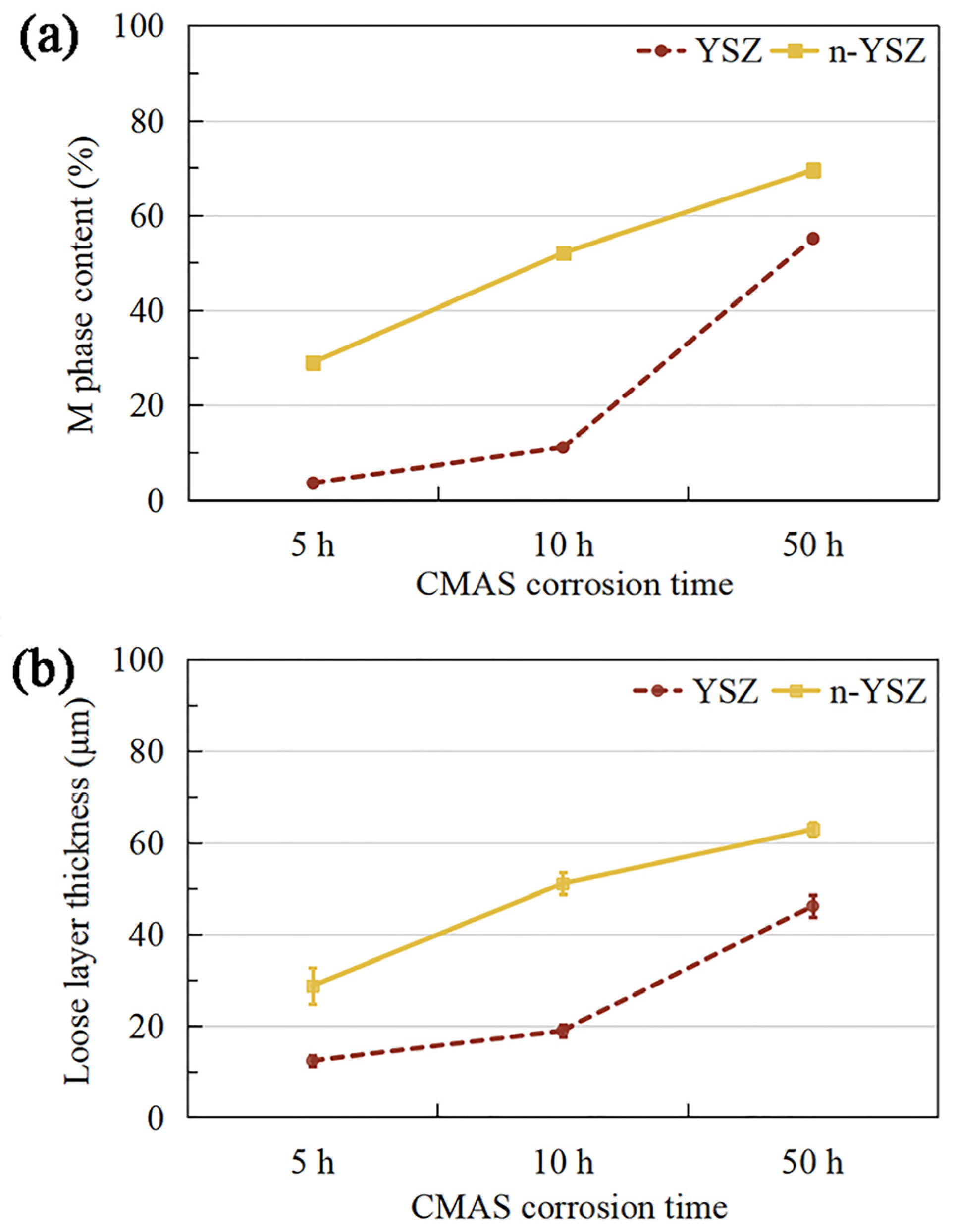
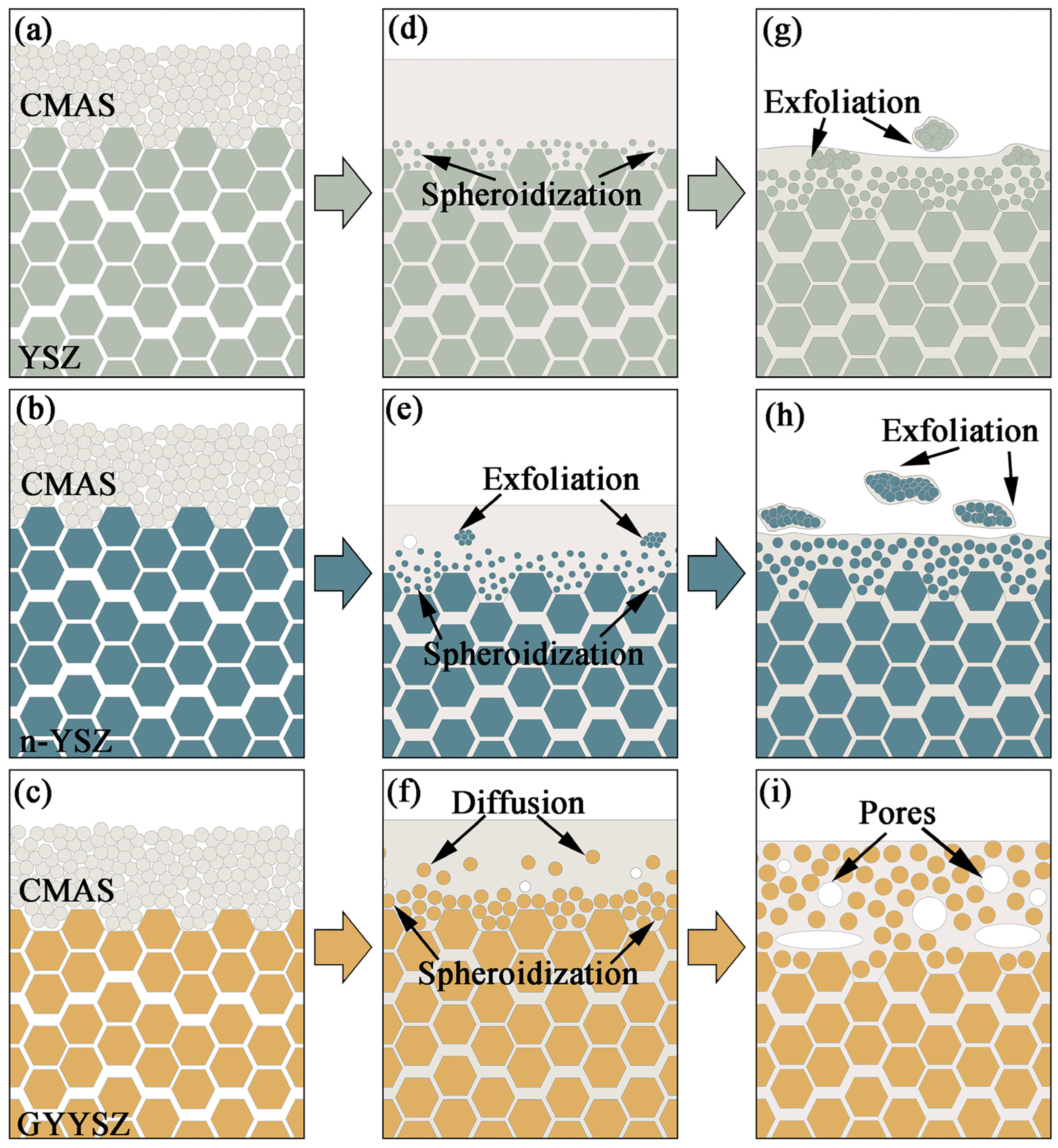
- Loose layers consisting of fine spherical m-ZrO2 particles are formed in both corroded n-YSZ and YSZ coatings. The thickness of loose layers and the degree of phase transition in the coatings increase with corrosion time. More pronounced phase transition and earlier spalling are observed in n-YSZ coatings compared with YSZ coatings.
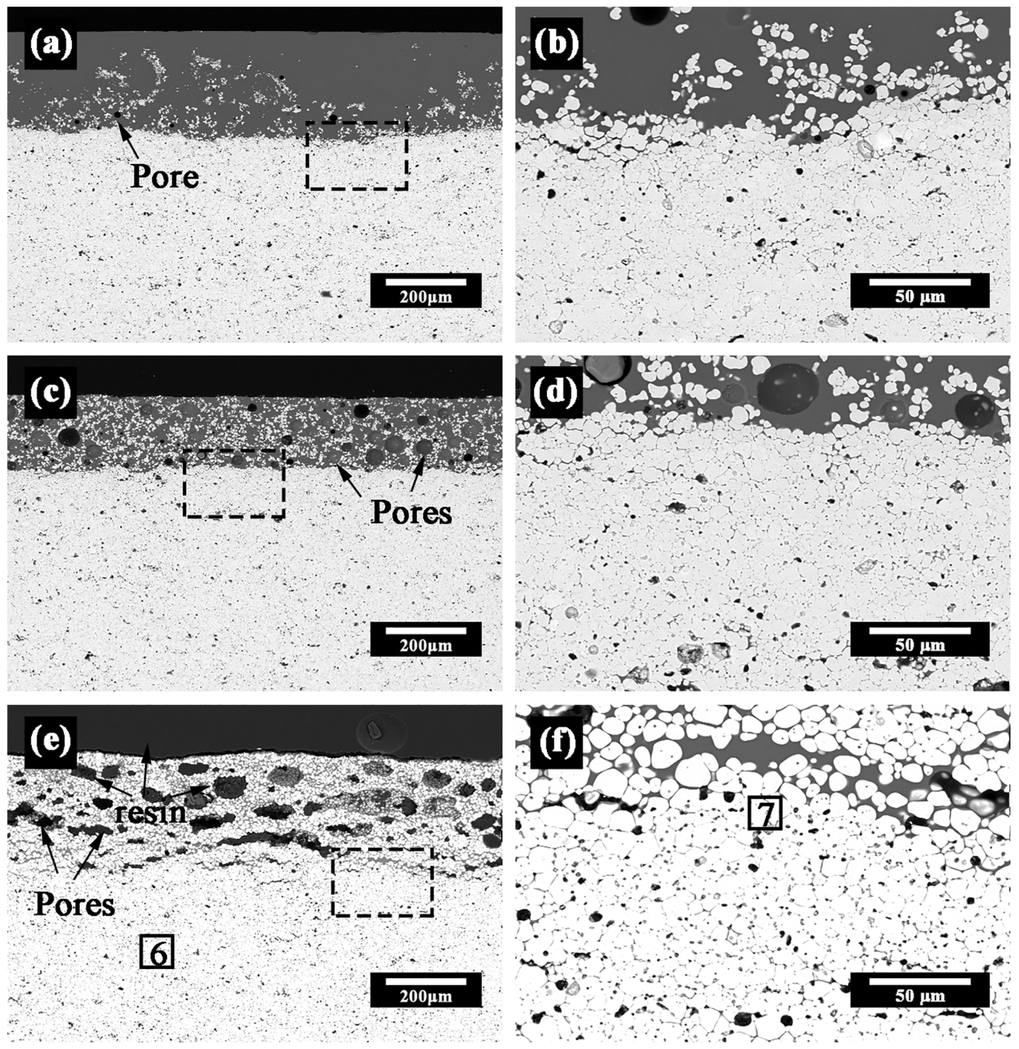
- No phase transition or exfoliation occurs in GYYSZ coating. Instead, the formation of coarse spherical particles in the coatings and diffusion into CMAS are observed.
- The CMAS corrosion resistance of the coatings follows the order: GYYSZ > YSZ > n-YSZ. Doping ZrO2 with Gd/Yb/Y elements enhances both the phase stability and the resistance to CMAS corrosion of the coatings.
Author Contributions
Funding
Institutional Review Board Statement
Informed Consent Statement
Data Availability Statement
Conflicts of Interest
References
- Padture, N.P.; Gell, M.; Jordan, E.H. Thermal Barrier Coatings for Gas-Turbine Engine Applications. Science 2002, 296, 280–284. [Google Scholar] [CrossRef]
- Wei, Z.-Y.; Meng, G.-H.; Chen, L.; Li, G.-R.; Liu, M.-J.; Zhang, W.-X.; Zhao, L.-N.; Zhang, Q.; Zhang, X.-D.; Wan, C.-L.; et al. Progress in Ceramic Materials and Structure Design toward Advanced Thermal Barrier Coatings. J. Adv. Ceram. 2022, 11, 985–1068. [Google Scholar] [CrossRef]
- Li, P.; Jin, X.; Lu, P.; Liu, D.; Mou, R.; Fan, X. Comparative Study on Microstructure Evolution and Failure Mechanisms of Ordinary and Refurbished EB-PVD TBC under Cyclic Oxidation. J. Adv. Ceram. 2023. [Google Scholar] [CrossRef]
- Chinnusamy, S.; Ramasamy, V.; Venkatajalapathy, S.; Kaliyannan, G.V.; Palaniappan, S.K. Experimental Investigation on the Effect of Ceramic Coating on the Wear Resistance of Al6061 Substrate. J. Mater. Res. Technol. 2019, 8, 6125–6133. [Google Scholar] [CrossRef]
- Bakan, E.; Vaßen, R. Ceramic Top Coats of Plasma-Sprayed Thermal Barrier Coatings: Materials, Processes, and Properties. J. Therm. Spray Tech. 2017, 26, 992–1010. [Google Scholar] [CrossRef]
- Naumenko, D.; Pillai, R.; Chyrkin, A.; Quadakkers, W.J. Overview on Recent Developments of Bondcoats for Plasma-Sprayed Thermal Barrier Coatings. J. Therm. Spray Tech. 2017, 26, 1743–1757. [Google Scholar] [CrossRef]
- Saillard, A.; Cherkaoui, M.; Capolungo, L.; Busso, E.P. Stress Influence on High Temperature Oxide Scale Growth: Modeling and Investigation on a Thermal Barrier Coating System. Philos. Mag. 2010, 90, 2651–2676. [Google Scholar] [CrossRef]
- Li, C.L.; Wang, W.; Tan, S.L.; Song, S.G. Bond Strength and Oxidation Resistance of YSZ/(Ni, Al) Composite Coatings. Surf. Eng. 2014, 30, 619–623. [Google Scholar] [CrossRef]
- Witz, G.; Shklover, V.; Steurer, W.; Bachegowda, S.; Bossmann, H.-P. Phase Evolution in Yttria-Stabilized Zirconia Thermal Barrier Coatings Studied by Rietveld Refinement of X-Ray Powder Diffraction Patterns. J. Am. Ceram. Soc. 2007, 90, 2935–2940. [Google Scholar] [CrossRef]
- Cheng, B.; Zhang, Y.-M.; Yang, N.; Zhang, M.; Chen, L.; Yang, G.-J.; Li, C.-X.; Li, C.-J. Sintering-Induced Delamination of Thermal Barrier Coatings by Gradient Thermal Cyclic Test. J. Am. Ceram. Soc. 2017, 100, 1820–1830. [Google Scholar] [CrossRef]
- Hayashi, Y.; Lokachari, S.; Yamagishi, S.; Okazaki, M. CMAS Damage in Thermal Barrier Coatings: An Exploration via Single Crystal Bulk YSZ Specimen. Mech. Eng. Lett. 2016, 2, 16–00240. [Google Scholar] [CrossRef]
- Wu, Y.; Luo, H.; Cai, C.; Wang, Y.; Zhou, Y.; Yang, L.; Zhou, G. Comparison of CMAS Corrosion and Sintering Induced Microstructural Characteristics of APS Thermal Barrier Coatings. J. Mater. Sci. Technol. 2019, 35, 440–447. [Google Scholar] [CrossRef]
- Satpathy, R.; Rani, S.; Alam, Z.; Besra, L. Effectiveness of Lanthanum Zirconate and Yttria Stabilised Zirconia Freestanding APS Thermal Barrier Coatings against Natural CMAS Attack at High Temperatures. Mater. High. Temp. 2020, 37, 416–424. [Google Scholar] [CrossRef]
- Wang, H.; Sheng, Z.; Tarwater, E.; Zhang, X.; Fergus, J.W. Function of Reaction Layer in Pyrochlore Thermal Barrier Coatings against CMAS Corrosion. ECS Trans. 2015, 66, 53–59. [Google Scholar] [CrossRef]
- Deng, W.; Fergus, J.W. Effect of CMAS Composition on Hot Corrosion Behavior of Gadolinium Zirconate Thermal Barrier Coating Materials. J. Electrochem. Soc. 2017, 164, C526–C531. [Google Scholar] [CrossRef]
- Wang, F.; Guo, L.; Wang, C.; Ye, F. Calcium-Magnesium-Alumina-Silicate (CMAS) Resistance Characteristics of LnPO4 (Ln = Nd, Sm, Gd) Thermal Barrier Oxides. J. Eur. Ceram. Soc. 2017, 37, 289–296. [Google Scholar] [CrossRef]
- Guo, L.; Yan, Z.; Wang, X.; He, Q. Ti2AlC MAX Phase for Resistance against CMAS Attack to Thermal Barrier Coatings. Ceram. Int. 2019, 45, 7627–7634. [Google Scholar] [CrossRef]
- Liu, S.; Liu, Q.; Hu, X.; Guo, J.; Zhu, W.; Zhang, F.; Xia, J. CMAS Corrosion Resistance Behavior and Mechanism of Hf6Ta2O17 Ceramic as Potential Material for Thermal Barrier Coatings. Coatings 2023, 13, 404. [Google Scholar] [CrossRef]
- Boissonnet, G.; Chalk, C.; Nicholls, J.R.; Bonnet, G.; Pedraza, F. Thermal Insulation of YSZ and Erbia-Doped Yttria-Stabilised Zirconia EB-PVD Thermal Barrier Coating Systems after CMAS Attack. Materials 2020, 13, 4382. [Google Scholar] [CrossRef]
- Fan, W.; Bai, Y.; Liu, Y.F.; Kang, Y.X.; Wang, Y.; Wang, Z.Z.; Tao, W.Z. Corrosion Behavior of Sc2O3–Y2O3 Co-Stabilized ZrO2 Thermal Barrier Coatings with CMAS Attack. Ceram. Int. 2019, 45, 15763–15767. [Google Scholar] [CrossRef]
- Bal, E.; Karabaş, M.; Yılmaz Taptık, İ. The Effect of CMAS Interaction on Thermal Cycle Lifetime of YSZ Based Thermal Barrier Coatings. Mater. Res. Express 2018, 5, 065201. [Google Scholar] [CrossRef]
- Wang, Z.; Zhang, J.; Han, S.; Liu, J. Corrosion Resistance of Modified YSZ Coatings Subjected to CMAS Attacks. Surf. Eng. 2022, 38, 393–401. [Google Scholar] [CrossRef]
- Yuan, K.; Yang, L.; Wang, Q.; Zhang, F.; Zhu, W.; Zhou, Y. Al2O3–TiO2 Codoped Yttria-Stabilized Zirconia Thermal Barrier Coatings Resistant to Damage by Molten Calcium-Magnesium-Alumino-Silicate (CMAS) Glass. Adv. Eng. Mater. 2021, 23, 2001338. [Google Scholar] [CrossRef]
- Liu, H.; Cai, J.; Zhu, J. CMAS (CaO–MgO–Al2O3–SiO2) Resistance of Y2O3-Stabilized ZrO2 Thermal Barrier Coatings with Pt Layers. Ceram. Int. 2018, 44, 452–458. [Google Scholar] [CrossRef]
- Zhang, X.; Zhou, K.; Xu, W.; Chen, B.; Song, J.; Liu, M. In Situ Synthesis of α-Alumina Layer on Thermal Barrier Coating for Protection against CMAS (CaO–MgO–Al2O3–SiO2) Corrosion. Surf. Coat. Technol. 2015, 261, 54–59. [Google Scholar] [CrossRef]
- Jonnalagadda, K.P.; Peng, R.L.; Mahade, S.; Markocsan, N.; Nylén, P.; Björklund, S.; Curry, N.; Li, X.-H. Hot Corrosion Behavior of Multi-Layer Suspension Plasma Sprayed Gd2Zr2O7/YSZ Thermal Barrier Coatings. Interceram-Int. Ceram. Rev. 2017, 66, 180–184. [Google Scholar] [CrossRef]
- Mahade, S.; Curry, N.; Björklund, S.; Markocsan, N.; Joshi, S. Durability of Gadolinium Zirconate/YSZ Double-Layered Thermal Barrier Coatings under Different Thermal Cyclic Test Conditions. Materials 2019, 12, 2238. [Google Scholar] [CrossRef] [PubMed]
- Kang, Y.X.; Bai, Y.; Wang, Y.; Su, X.L. Degradation and Failure of a Novel Double-Layer LC/YSZ Thermal Barrier Coating in a Burner Rig Corrosion Test. Mater. High Temp. 2023, 1–14. [Google Scholar] [CrossRef]
- Guo, L.; Li, G.; Gan, Z. Effects of Surface Roughness on CMAS Corrosion Behavior for Thermal Barrier Coating Applications. J. Adv. Ceram. 2021, 10, 472–481. [Google Scholar] [CrossRef]
- Avcı, A.; Karabaş, M.; Akdoğan Eker, A.; Akman, E.; Aslan, C. Hot Corrosion and CMAS Degradation of Laser-Glazed YSZ Coating with Optimum Parameter. Proc. Inst. Mech. Eng. Part L J. Mater. Des. Appl. 2023, 146442072311781. [Google Scholar] [CrossRef]
- Wang, Y.; Xu, Z.; Wang, W.; Zhang, C.; Yu, Z.; Fang, H.; Yang, T. Preparation and CMAS Wettability Investigation of CMAS Corrosion Resistant Protective Layer with Micro-Nano Double Scale Structure. Coatings 2022, 12, 648. [Google Scholar] [CrossRef]
- Moriarty, P. Nanostructured Materials. Rep. Prog. Phys. 2001, 64, 297–381. [Google Scholar] [CrossRef]
- Malkiel, I.; Mrejen, M.; Nagler, A.; Arieli, U.; Wolf, L.; Suchowski, H. Plasmonic Nanostructure Design and Characterization via Deep Learning. Light Sci. Appl. 2018, 7, 60. [Google Scholar] [CrossRef] [PubMed]
- Velu Kaliyannan, G.; Palanisamy, S.V.; Rathanasamy, R.; Palanisamy, M.; Palaniappan, S.K.; Chinnasamy, M. Influence of Ultrathin Gahnite Anti-Reflection Coating on the Power Conversion Efficiency of Polycrystalline Silicon Solar Cell. J. Mater. Sci. Mater. Electron. 2020, 31, 2308–2319. [Google Scholar] [CrossRef]
- Li, M.; Cheng, Y.; Guo, L.; Zhang, Y.; Zhang, C.; He, S.; Sun, W.; Ye, F. Preparation of Nanostructured Gd2Zr2O7-LaPO4 Thermal Barrier Coatings and Their Calcium-Magnesium-Alumina-Silicate (CMAS) Resistance. J. Eur. Ceram. Soc. 2017, 37, 3425–3434. [Google Scholar] [CrossRef]
- Zhou, X.; Chen, T.; Yuan, J.; Deng, Z.; Zhang, H.; Jiang, J.; Cao, X. Failure of Plasma Sprayed Nano-zirconia-based Thermal Barrier Coatings Exposed to Molten CaO-MgO-Al2O3-SiO2 Deposits. J. Am. Ceram. Soc. 2019, 102, 6357–6371. [Google Scholar] [CrossRef]
- Bahamirian, M.; Hadavi, S.M.M.; Farvizi, M.; Keyvani, A.; Rahimipour, M.R. Hot Corrosion Behavior of ZrO2 9.5Y2O3 5.6Yb2O3 5.2Gd2O3 TBCs in CMAS: CaO-MgO-Al2O3-SiO2. J. Aust. Ceram. Soc. 2021, 57, 215–224. [Google Scholar] [CrossRef]
- Li, Y.; She, Y.; Liao, K. Hot-Corrosion Behavior of Gd2O3–Yb2O3 Co-Doped YSZ Thermal Barrier Coatings in the Presence of V2O5 Molten Salt. Coatings 2023, 13, 886. [Google Scholar] [CrossRef]
- Wang, T.; Shao, F.; Ni, J.; Zhao, H.; Zhuang, Y.; Sheng, J.; Zhong, X.; Yang, J.; Tao, S.; Yang, K. Calcium-Magnesium-Aluminum-Silicate (CMAS) Corrosion Resistance of Y-Yb-Gd-Stabilized Zirconia Thermal Barrier Coatings. J. Therm. Spray Tech. 2021, 30, 442–456. [Google Scholar] [CrossRef]
- Borom, M.P.; Johnson, C.A.; Peluso, L.A. Role of Environment Deposits and Operating Surface Temperature in Spallation of Air Plasma Sprayed Thermal Barrier Coatings. Surf. Coat. Technol. 1996, 86–87, 116–126. [Google Scholar] [CrossRef]
- Li, D.; Jiang, P.; Gao, R.; Sun, F.; Jin, X.; Fan, X. Experimental and Numerical Investigation on the Thermal and Mechanical Behaviours of Thermal Barrier Coatings Exposed to CMAS Corrosion. J. Adv. Ceram. 2021, 10, 551–564. [Google Scholar] [CrossRef]
- Krämer, S.; Yang, J.; Levi, C.G. Infiltration-Inhibiting Reaction of Gadolinium Zirconate Thermal Barrier Coatings with CMAS Melts. J. Am. Ceram. Soc. 2008, 91, 576–583. [Google Scholar] [CrossRef]
- Krämer, S.; Yang, J.; Levi, C.G.; Johnson, C.A. Thermochemical Interaction of Thermal Barrier Coatings with Molten CaO-MgO-Al2O3-SiO2 (CMAS) Deposits. J. Am. Ceram. Soc. 2006, 89, 3167–3175. [Google Scholar] [CrossRef]
- Guo, L.; Xin, H.; Li, Y.; Yu, Y.; Yan, Z.; Hu, C.; Ye, F. Self-Crystallization Characteristics of Calcium-Magnesium-Alumina- Silicate (CMAS) Glass under Simulated Conditions for Thermal Barrier Coating Applications. J. Eur. Ceram. Soc. 2020, 40, 5683–5691. [Google Scholar] [CrossRef]
- Aygun, A.; Vasiliev, A.L.; Padture, N.P.; Ma, X. Novel Thermal Barrier Coatings That Are Resistant to High-Temperature Attack by Glassy Deposits. Acta Mater. 2007, 55, 6734–6745. [Google Scholar] [CrossRef]
- Turkdogan, E.T. Physical Chemistry of High Temperature Technology; Academic Press: New York, NY, USA, 1980; ISBN 978-0-12-704650-1. [Google Scholar]
- Chiu, C.; Tseng, S.; Chao, C.; Fan, X.; Cheng, W. Interfacial Stresses of Thermal Barrier Coating with Film Cooling Holes Induced by CMAS Infiltration. Coatings 2022, 12, 326. [Google Scholar] [CrossRef]
- Mohan, P.; Yuan, B.; Patterson, T.; Desai, V.; Sohn, Y.H. Degradation of Yttria Stabilized Zirconia Thermal Barrier Coatings by Molten CMAS (CaO-MgO-Al2O3-SiO2) Deposits. MSF 2008, 595–598, 207–212. [Google Scholar] [CrossRef]
- Ahmed, Q.; Qureshi, I.N.; Salam, I.U. Investigation of Hot Section (Nozzle Guiding Vane) Distress Due to Interaction of Thermal Barrier Coatings with CMAS. KEM 2018, 778, 245–250. [Google Scholar] [CrossRef]
- Wang, J.; Chen, L.; Wang, M.; Zhang, C.; Yu, Y.; Sun, J.; Chen, X.; Wang, Y.; Liu, P.; Jing, Q. Influence of Gd2O3 Substitution on Thermal and Mechanical Properties of ZrO2-Ta2O5-Y2O3. J. Eur. Ceram. Soc. 2021, 41, 1654–1663. [Google Scholar] [CrossRef]
- Stott, F.H.; de Wet, D.J.; Taylor, R. Degradation of Thermal-Barrier Coatings at Very High Temperatures. MRS Bull. 1994, 19, 46–49. [Google Scholar] [CrossRef]
- Liu, Y.; Cao, Z.; Yuan, J.; Sun, X.; Su, H.; Wang, L. Effect of Morphology, Impact Velocity and Angle of the CaO-MgO-Al2O3-SiO2 (CMAS) Particle on the Erosion Behavior of Thermal Barrier Coatings (TBCs): A Finite Element Simulation Study. Coatings 2022, 12, 576. [Google Scholar] [CrossRef]
- Levi, C.G.; Hutchinson, J.W.; Vidal-Sétif, M.-H.; Johnson, C.A. Environmental Degradation of Thermal-Barrier Coatings by Molten Deposits. MRS Bull. 2012, 37, 932–941. [Google Scholar] [CrossRef]
- Nieto, A.; Agrawal, R.; Bravo, L.; Hofmeister-Mock, C.; Pepi, M.; Ghoshal, A. Calcia–Magnesia–Alumina–Silicate (CMAS) Attack Mechanisms and Roadmap towards Sandphobic Thermal and Environmental Barrier Coatings. Int. Mater. Rev. 2021, 66, 451–492. [Google Scholar] [CrossRef]
- Krause, A.R.; Garces, H.F.; Dwivedi, G.; Ortiz, A.L.; Sampath, S.; Padture, N.P. Calcia-Magnesia-Alumino-Silicate (CMAS)-Induced Degradation and Failure of Air Plasma Sprayed Yttria-Stabilized Zirconia Thermal Barrier Coatings. Acta Mater. 2016, 105, 355–366. [Google Scholar] [CrossRef]


| Composition (in wt.%) | Granularity (μm) | Manufacturer |
|---|---|---|
| 6-8Y2O3-ZrO2 | 20–60 | Imerys (Shenyang, China) |
| Nano 6-8Y2O3-ZrO2 | 31–63 | Shiyuan (Suzhou, China) |
| 5.2Gd2O3-5.6Yb2O3-9.5Y2O3-ZrO2 | 30–74 | Institute of Metals, China Academy of Sciences (Shenyang, China) |
| Parameter | Unit | Value |
|---|---|---|
| Voltage | V | 70 |
| Current | A | 590 |
| Primary gas, Ar | slpm (standard liter per minute) | 38 |
| Secondary gas, H2 | slpm (standard liter per minute) | 1.8 |
| Spray distance | mm | 90 |
| Gd (wt.%) | Yb (wt.%) | Y (wt.%) | Zr (wt.%) | O (wt.%) | RE/Zr | |
|---|---|---|---|---|---|---|
| 1 | - | - | 6.86 | 69.43 | 23.71 | 0.10 |
| 2 | - | - | 7.12 | 69.31 | 23.58 | 0.10 |
| 3 | 5.54 | 6.06 | 8.98 | 58.93 | 20.50 | 0.35 |
| Gd (wt.%) | Yb (wt.%) | Y (wt.%) | Zr (wt.%) | Ca (wt.%) | Mg (wt.%) | Al (wt.%) | Si (wt.%) | O (wt.%) | RE/Zr | |
|---|---|---|---|---|---|---|---|---|---|---|
| 1 | - | - | 1.33 | 3.48 | 23.11 | 3.72 | 7.34 | 20.20 | 40.82 | 0.38 |
| 2 | - | - | 5.75 | 67.11 | 1.39 | 0.29 | 0.56 | 1.70 | 23.21 | 0.09 |
| 3 | - | - | 3.09 | 66.82 | 2.33 | 0.37 | 0.79 | 2.61 | 23.99 | 0.05 |
| 4 | - | - | 4.86 | 66.68 | 1.65 | 0.37 | 0.63 | 2.03 | 23.78 | 0.07 |
| 5 | - | - | 2.90 | 61.69 | 3.05 | 0.57 | 1.08 | 3.27 | 27.44 | 0.05 |
| 6 | 4.79 | 5.38 | 8.53 | 58.16 | 0.79 | 0.18 | 0.20 | 0.85 | 21.13 | 0.32 |
| 7 | 4.76 | 5.19 | 8.23 | 58.65 | 1.31 | 0.18 | 0.27 | 1.14 | 20.27 | 0.31 |
| Gd (wt.%) | Yb (wt.%) | Y (wt.%) | Zr (wt.%) | Ca (wt.%) | Mg (wt.%) | Al (wt.%) | Si (wt.%) | O (wt.%) | RE/Zr | |
|---|---|---|---|---|---|---|---|---|---|---|
| 1 | - | - | 1.36 | 3.17 | 23.20 | 3.79 | 7.31 | 20.11 | 41.06 | 0.43 |
| 2 | - | - | 3.19 | 66.79 | 1.80 | 0.36 | 0.62 | 1.88 | 25.35 | 0.05 |
| 3 | - | - | 3.02 | 72.07 | 0.73 | 0.21 | 0.30 | 1.00 | 22.67 | 0.04 |
| 4 | - | - | 2.45 | 65.71 | 2.13 | 0.53 | 0.80 | 2.29 | 26.09 | 0.04 |
| 5 | - | - | 2.63 | 55.62 | 5.96 | 0.96 | 2.02 | 5.77 | 27.04 | 0.05 |
| 6 | - | - | 2.61 | 67.67 | 1.50 | 0.23 | 0.48 | 1.72 | 25.80 | 0.04 |
| 7 | - | - | 2.83 | 78.85 | 0.59 | 0 | 0.01 | 0.79 | 16.93 | 0.04 |
| 8 | 5.30 | 5.66 | 8.49 | 58.57 | 0.63 | 0.20 | 0.10 | 0.55 | 20.50 | 0.33 |
| 9 | 4.39 | 5.14 | 8.16 | 61.27 | 1.12 | 0.10 | 0.04 | 0.51 | 19.28 | 0.29 |
| 10 | 3.43 | 4.55 | 6.75 | 55.46 | 3.09 | 0.44 | 0.62 | 2.11 | 23.55 | 0.27 |
Disclaimer/Publisher’s Note: The statements, opinions and data contained in all publications are solely those of the individual author(s) and contributor(s) and not of MDPI and/or the editor(s). MDPI and/or the editor(s) disclaim responsibility for any injury to people or property resulting from any ideas, methods, instructions or products referred to in the content. |
© 2023 by the authors. Licensee MDPI, Basel, Switzerland. This article is an open access article distributed under the terms and conditions of the Creative Commons Attribution (CC BY) license (https://creativecommons.org/licenses/by/4.0/).
Share and Cite
Zou, L.; Gao, M.; Xu, N.; Zhang, J.; Chang, X. CMAS Corrosion Behavior of Nanostructured YSZ and Gd-Yb-Y-Stabilized Zirconia Coatings. Coatings 2023, 13, 1623. https://doi.org/10.3390/coatings13091623
Zou L, Gao M, Xu N, Zhang J, Chang X. CMAS Corrosion Behavior of Nanostructured YSZ and Gd-Yb-Y-Stabilized Zirconia Coatings. Coatings. 2023; 13(9):1623. https://doi.org/10.3390/coatings13091623
Chicago/Turabian StyleZou, Lanxin, Minghao Gao, Na Xu, Jia Zhang, and Xinchun Chang. 2023. "CMAS Corrosion Behavior of Nanostructured YSZ and Gd-Yb-Y-Stabilized Zirconia Coatings" Coatings 13, no. 9: 1623. https://doi.org/10.3390/coatings13091623
APA StyleZou, L., Gao, M., Xu, N., Zhang, J., & Chang, X. (2023). CMAS Corrosion Behavior of Nanostructured YSZ and Gd-Yb-Y-Stabilized Zirconia Coatings. Coatings, 13(9), 1623. https://doi.org/10.3390/coatings13091623