Abstract
This work characterizes the orientation behavior of nematic liquid crystals in pressure-driven flows of microfluidic channels at interfaces between the flow and microchannel walls. The impact of flow velocity and microchannel geometry on the orientation of liquid crystals in single-phase and two-phase flows is discussed. Polarizing optical microscopy images revealed the homeotropic orientation of liquid crystal molecules at microchannel walls at zero flow velocities, which gradually transitioned into planar alignment along the microchannel axis when the flow velocity increased in the 50 μm/s to 5 mm/s range. Liquid crystal droplets demonstrated homeotropic or planar alignment depending on the sizes of droplets and flow velocities. The polarized light pattern from homeotropically aligned droplets deposited on microchannel walls was found to be logarithmically proportional to the flow velocity in the 2 to 40 mm/s range. The revealed behavior of nematic liquid crystals at microchannel wall surfaces in dynamic flow conditions offers new tools for on-demand control of the optical properties of microfluidic devices and can contribute to the development of analytical lab-on-chip tools with internal continuous or discrete liquid crystal layers for flow characterization in microchannel confinement.
1. Introduction
Liquid crystal (LC) systems have attracted a sustainable fundamental and applied research interest as supramolecular materials with smart stimuli-responsive capabilities [1,2,3]. They are in constant demand for use in emerging applications in photonics [4,5,6], shape-memory materials [3], sensors and actuators [2,7,8], security labeling [9,10], and in the fabrication of composites with polymers [11,12] and quantum dots [13,14] for molecular electronics and medicine. Important applications of LCs as smart materials involve liquid crystal [5,15] or composite [4,16] coatings and films for smart windows [17], haptics [18], or electro-optical devices [16]. Orientation behavior is a key characteristic of liquid crystals that is responsible for their optical properties and for applications as functional supramolecular materials such as individual LC systems or their composites with polymers or quantum dots [11,12,13,17,19].
Microfluidics is a promising area of science and technology that expands the modification [6,8,20] and application [7,21,22] horizons for liquid crystal systems. Non-equilibrium microfluidic confinement brings new options for the precise control of supramolecular materials [23,24,25] by performing their fabrication and modification in confined single-phase or multiphase flows [24,26,27,28]. An important focus of current research is modifying the internal surfaces of microchannels with supramolecular materials [29,30,31] or biological species [32,33,34,35] and creating functional coatings for nanotechnology and medicine.
Liquid crystal molecules exhibit various orientation states with respect to microchannel walls depending on flow conditions [36,37,38,39,40] or the presence of an immiscible liquid [41,42,43,44]. The stimuli-responsive orientation behavior of liquid crystal layers provides them with intrinsic sensing capabilities in microfluidic confinement with its high surface-to-volume ratio [45,46]. Microfluidic liquid crystal layers manipulate liquid mobility [47], generate luminescence readout [48], and perform biosensing by changing their orientation states [49,50].
Liquid crystal microdroplets, in their turn, are used for a variety of sensing applications: biosensors for the detection of metabolic acids [51], the on-chip detection of antimicrobial peptides [52], and the determination of pH [53]. Microfluidic devices are convenient platforms for producing liquid crystal droplets [54] and coating them with polymers or other agents [52,54,55,56] to obtain microcapsules for sensing or biomedical applications. Flow conditions are expected to exert a considerable influence on the orientation behavior of LC molecules at the LC-flow interface.
Although the orientation behavior of LC systems in dynamic conditions of microfluidic interfaces is important for their sensing applications, current studies focus mostly on the characterization of liquid crystal flows in the body of microchannels of various geometry. Major attention has been given to either flow-induced transitions in single-phase LC flows or the generation of LC droplets without an integrated discussion of orientation phenomena at liquid-wall or liquid-liquid interfaces. A comparative and integrated study of LC orientation at microchannel walls and immiscible fluid interfaces in dynamic flow conditions may bring useful insights into the modification of microchannels using functional LC coatings and provide them with additional sensing and optical activity properties.
The goal of this work is to characterize the orientation behavior of a nematic liquid crystal at the walls of microfluidic channels in dynamic conditions of single-phase and two-phase flows. The orientation of LC molecules near microchannel walls and at interfaces between LC flow and aqueous media in two-phase droplets and threads was studied. Quantitative correlations between the orientation states of liquid crystal molecules at these interfaces and the microchip operation parameters in a broad range of flow rates were found. Additional flow sensing capabilities can be provided for microchannels with deposited continuous or dispersed layers of liquid crystal materials.
2. Materials and Methods
2.1. Materials
Microfluidic devices were fabricated from polydimethylsiloxane (PDMS) SylgardTM 184 silicone elastomer. PDMS was purchased from Dow Corning (Midland, MI, USA) and used as received. It came as a two-part elastomer kit (the pre-polymer and curing agent). SU-8 3050 photoresist (Microchem Corp., Westborough, MA, USA) and was used to produce a mold for microfluidic chips.
For the liquid crystal phase, the nematic liquid crystal ZhK-1282 was used. It was purchased from NIOPIK, Moscow, Russia, and used as received. It exhibits liquid crystal properties in a broad temperature range, including room temperature. Liquid crystal properties and the phase behavior of this LC material were characterized in our previous work [19].
For the aqueous phase, a solution of sodium dodecyl sulfate (SDS) in water was used. SDS was purchased from BDH Limited, Poole, England, and used as received. SDS was sold as a powder. Bulk samples of pre-micellar 5 × 10⁻³ mol/L SDS were produced by dissolving dry surfactant in water. The critical micellization concentration of SDS is 8.4 × 10⁻³ mol/L [57]. Deionized water (18.2 MΩ-cm) was used for all solutions. Before performing microfluidic experiments, the solvent was passed through 0.45 µm Millipore polytetrafluoroethylene (PTFE) filters, by Merck, Darmstadt, Germany.
2.2. Methods
Initial analysis of two-phase LC-aqueous flows and the flow conditions that correspond to the formation of liquid crystal droplets and threads of liquid crystals were analyzed by digital optical microscopy using a Levenhuk D320 optical microscope (Levenhuk, Tampa, FL, USA). Microchannels and LC-aqueous media were imaged at 100× magnification using a Levenhuk M1400 Plus camera (Levenhuk, Tampa, FL, USA).
Orientation behavior of the liquid crystal in microfluidic flows was studied by polarized optical microscopy (POM) using an Olympus BX51 microscope (Olympus, Tokyo, Japan) equipped with a high-precision Linkam heating system. Single-phase and multiphase LC media were imaged at 100× and 500× magnification using the built-in Olympus digital microscope camera (Olympus, Tokyo, Japan).
Droplet sizes and angles between droplet orientation patterns in polarized light were measured by Levenhuk ToupView software (version 3.7.6273). LC droplet diameters were measured using the width of microchannel as the reference distance. Angle measurement experiments were repeated at least three times for each droplet size and flow rate. Evaluation of experimental errors was performed by Matlab 2021 software.
The LC and aqueous phases were infused into microfluidic devices using Shenchen ISPLab01 syringe pumps (Baoding Shenchen Precision Pump Co. Ltd., Baoding, China), which provide a minimal flow rate of 0.001 µL/min. In this work, the flow rates of LC and aqueous phases were varied in the range from 0.1 to 50 µL/min. To provide the same hydraulic path of fluids to all the inlets, PTFE tubes of identical lengths (10 cm) and internal diameters that fit the same needle tips inserted into microchip outputs (20 G-type needles, 0.9 mm diameter) were used. These tubes were connected to identical 1 mL syringes with LC and aqueous phases installed into syringe pumps.
Microfluidic devices were fabricated using standard photolithography techniques [58]. The chips with rectangular microchannels were produced by this technology. The length, width, and height of all the chips were 16 mm, 200 μm, and 100 μm, respectively. SU-8 photoresist and a transparent photomask with a negative image of a microchip were used to produce a 100 µm thick mold of microfluidic chips on top of a 3-inch silicon wafer. PDMS pre-polymer was mixed with a curing agent, poured over the mold, and allowed to cure for 4 h in a 60 °C oven. Once cured, PDMS was peeled off the mold and bonded to a flat PDMS slab via 1 min plasma treatment by Harrick Plasma Cleaner PDC-23G, Ithaca, NY, USA. The PDMS device was then heated in an oven at 180 °C for 1 h to complete the bonding of the two polymer layers.
3. Results
3.1. Selection of Flow Modes for Generating Microfluidic Liquid Crystal Systems
At the first stage of the work, microchip operation modes suitable for generating single-phase and two-phase LC flows were identified. Figure 1 demonstrates the design of the microfluidic devices we used for experiments and the resulting two-phase flows.
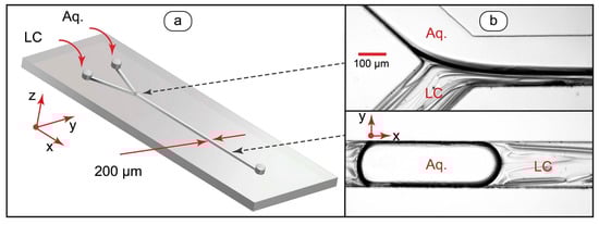
Figure 1.
Design of microfluidic device for generating liquid crystal flows (a) and optical microscopy images of LC-water droplets and threads in microchannels (b).
Single-phase flows can be generated by setting the flow rate of the aqueous phase to zero. The orientation behavior of single-phase LC flows in the microchannel was controlled by varying the infusion flow rate through the LC inlet shown in Figure 1a and stopping the infusion through the aqueous phase inlet.
Multiphase microfluidic LC systems are more complex as compared to single-phase LC flows and can be represented by various size droplets or threads of immiscible liquids depending on flow conditions. The formation of such systems and transitions between them in a microchannel can be controlled by chip geometry and the properties of contacting fluids [59,60,61].
Two parameters conveniently characterize transitions between droplets and fluid threads in microchannels [62]. The first parameter is the capillary number:
where μ is the viscosity of a continuous phase, U is the flow velocity in the main channel, and γ is the interfacial tension between two immiscible liquids.
The second parameter is the ratio of liquid crystal and aqueous phase flow rates:
where QLC is the liquid crystal phase flow rate and QAq is the aqueous phase flow rate.
At lower capillary numbers (Ca < 0.01), the chip is in a droplet generation mode, while at higher capillary numbers (Ca > 0.1), coflowing threads form. At intermediate capillary numbers, coflowing fluid threads form immediately after the junction of inlets and then break up into droplets (Figure 1b).
It should be noted, however, that nematic liquid crystals are non-Newtonian liquids [63]. Their viscosities depend non-linearly on the flow velocity. Therefore, it may be difficult to calculate accurate values of Ca for the LC flows. The capillary number is, however, still useful for confined multiphase LC systems because it offers parameters, which can be varied to generate droplets and threads with an approximate predictive power. For two-phase liquid crystal and water flows in our experiments, droplets were formed by decreasing the flow velocity (below ≈2 mm/s). Stable threads were produced at higher (above ≈20 mm/s) flow velocities. By reducing interfacial tension with an added surfactant, the droplet-thread transition zone was moved to the lower flow velocity range of 0.5 to 5 mm/s. Finally, by varying the ratio of flow rates, LC droplets in the aqueous phase (φ ≈ 0.1–0.2), aqueous droplets in the LC phase (φ ≈ 8–10), and stable coflowing threads of various widths (φ ≈ 0.5–2) were generated in the above-given flow velocity range.
These microchip operation modes (flow velocities and ratios of flow rates) were used to control the generation of multiphase microfluidic systems in further experiments.
3.2. Orientation Behavior of Microfluidic Liquid Crystal Systems at Liquid-Wall Interfaces
The next step of this work focused on characterizing the orientation behavior of LC molecules at the liquid-wall interface inside microchannels using polarized optical microscopy. The initial experiments were made with single-phase LC flows and proceeded to two-phase LC-aqueous systems.
3.2.1. Single-Phase Flows
Polarized optical microscopy images of single-phase LC flows at various flow velocities are shown in Figure 2. The images were taken with crossed polarizers.
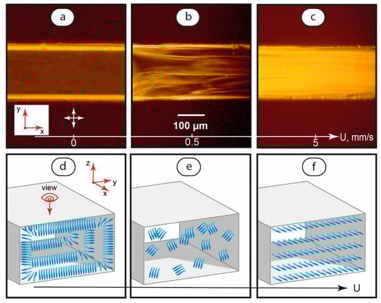
Figure 2.
Polarized optical microscopy images of LC flows in a microchannel at various flow velocities (a–c) and the respective suggested orientation of LC molecules (d–f). Red arrows demonstrate coordinate axes with respect to Figure 1. Crossed white arrows indicate positions of polarizers.
According to Figure 2a, immobile LC systems demonstrate a dark field in the central part of the channel. Such behavior indicates a homeotropic alignment of the LC molecules, which are oriented perpendicular to the microchannel’s top and bottom walls (Figure 2d).
The lines near microchannel walls represent 20–30 μm wide LC domains with molecules aligned perpendicular to microchannel side walls (Figure 2d). These lines are bright because we observe them from the top of the channel in cross-polarized light.
The orientation state shown in Figure 2a was observed to be sensitive to both very low initiated and residual flows. Instabilities started to appear at very low flow velocities of ≈40–50 μm/s and developed with increasing flow velocities up to ≈0.5 mm/s. In this velocity range, POM images showed alternating bright and dark areas in the microchannel (Figure 2b), which can be associated with a random orientation of the LC domains (Figure 2e).
Further increasing of the flow velocity in the range of 1 to 5 mm/s initiated a transition of the LC system to a bright-field flow (Figure 2c) of LC domains oriented along the flow axis. Such a flow represents a planar alignment of the LC molecules (Figure 2f).
The results obtained for single-phase flows agree with literature data on the microfluidic orientation behavior of other nematic LCs [36,37,64] with respect to the PDMS interface.
Therefore, in immobile single-phase microfluidic LC systems, a layer of microscale homeotropic LC domains forms at the liquid-wall interface. This layer is sensitive to slow flows starting from 40–50 μm/s. At higher flow velocities, transitions to random and planar alignment states occur in the entire body of the microchannel in a range of flow velocities up to 5 mm/s.
3.2.2. Two-Phase Flows
The injection of the aqueous phase flow to the microchip shown in Figure 1 led to the formation of two-phase LC-water systems in the main channel. Figure 3 summarizes POM images of two-phase LC-water systems generated in microchannels.
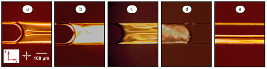
Figure 3.
Polarized optical microscopy images of LC-water flows in a microchannel at various flow conditions: U = 0, φ = 10 (a), U = 0.05 mm/s, φ = 10 (b), U = 0.5 mm/s, φ = 10 (c), U = 0.5 mm/s, φ = 0.1 (d), and U = 2 mm/s, φ = 1 (e). Red arrows demonstrate coordinate axes with respect to Figure 1. Crossed white arrows indicate positions of polarizers.
Depending on the flow velocity and the ratio of flow rates, the dispersion of water in the LC phase (Figure 3a–c), the dispersion of the LC phase in water (Figure 3d), or parallel LC-water threads (Figure 3e) can be obtained.
In two-phase experiments, a uniform homeotropic alignment of the mesophase molecules was not achieved in the majority of immobile LC-water systems within 15–20 min after turning off the syringe pumps. The pattern shown in Figure 3a may be associated with residual flows in two-phase systems. The observed instabilities were typical for the ones initiated by shear stresses at very low flow velocities of 50–100 μm/s [37]. The top parts of the microchannel were observed in POM images. Instabilities shown in Figure 3a emerge, therefore, in the top central part of the channel. This agrees with our previous modeling of shear stresses [65], which demonstrates that the highest shear rate develops at central areas of rectangular microchannel walls and initiates deviations from the homeotropic orientation of LC molecules in the respective areas of the LC-wall interface. This effect also confirms a trend for a continuous immobile LC layer to form at slow flows.
At low flow velocities (0.05 mm/s), the continuous LC phase shows a bright field (Figure 3b). The rotation of polarizers changes the color of this field. Such a bright field may represent a deformed homeotropic orientation of the LC molecules, which are slightly bent along the flow. Such an effect was reported in the literature for single-phase flows of similar nematic LCs [37]. It should be noted that this state was not steadily observed in the single-phase LC flows shown in Figure 2. The immobile single-phase LC system underwent a transition to the state shown in Figure 2b in the range of flow rates from 0.05 to 0.5 mm/s by forming instabilities. This system relaxed to the state shown in Figure 2a when the flow was stopped.
At the higher flow velocity of 0.5 mm/s, the continuous LC phase exhibits a random orientation of domains (Figure 3c), which is similar to the single-phase LC system under the same conditions.
LC droplets demonstrate a different orientation behavior as compared with a continuous LC phase in a two-phase LC-water system. After droplet break-up at the junction of the inlets, a chaotic dynamic structure of domains develops in droplets (Figure 3d). This pattern is sustainable for a broad range of flow velocities until the droplets transform into two-phase threads. Such a behavior agrees with literature data [66] and can be associated with intensive convection inside channel-wide droplets.
Finally, we observed a transition from LC-water disperse systems of both types to parallel threads of the LC and aqueous phases (Figure 3e). In the LC threads, we generally observe a similar planar orientation of the mesophase molecules, corresponding to that shown in Figure 2d for single-phase LC systems under similar flow conditions.
Therefore, in the continuous LC phase of the confined LC-water system, LC layers demonstrate deviations from the homeotropic orientation at the liquid-wall interfaces for low residual or initiated flow velocities. The orientation of the LC domains in LC droplets is dynamic and chaotic for the entire droplet body. A planar orientation is more typical for LC threads.
At the next stage of this work, the orientation behavior of mesophase molecules at LC-water interfaces in two-phase microflows was characterized.
3.3. Orientation Behavior of Microfluidic Liquid Crystal Systems at Liquid-Liquid Interfaces
3.3.1. Comparative Analysis of Mesophase Orientation in Droplets and Threads
To analyze the orientation behavior of liquid crystal molecules at LC-water interfaces in dynamic microfluidic conditions, polarized optical microscopy images at higher magnification (500×) were obtained and analyzed. Such images provided more detailed information about the properties of the mesophase at the boundary layers of LC droplets and threads. Figure 4 demonstrates examples of such interfacial boundaries.
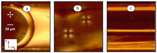
Figure 4.
Interfacial boundaries between LC and aqueous phases: microchannel-wide droplets, U = 0.1 mm/s (a); smaller droplets immobilized on the bottom wall of the microchannel, U = 0.1 mm/s (b); and LC-water thread, U = 2 mm/s (c). Red arrows demonstrate coordinate axes with respect to Figure 1. Crossed white arrows indicate positions of polarizers.
As Figure 4a shows, the interface between the aqueous droplet and the continuous LC phase demonstrates no peculiar orientations of mesophase molecules, at least from the observation direction in these experiments. Channel-wide LC droplets demonstrate chaotic convective motion and orientation of the mesophase domain in a broad range of flow rates, so they were not studied at a higher magnification.
Smaller LC droplets (Figure 4b) showed a considerably different orientation pattern in polarized light (Figure 4b). They exhibited a “Maltese Cross” texture [44], which rotated with the respective rotation of polarizers. In our experiments, such a texture was demonstrated by mobile droplets with diameters less than the microchannel width and also by droplets immobilized at the bottom of the microchannel. Such a texture indicated that the mesophase molecules are oriented perpendicular to the LC-water boundary.
In LC-water threads, we observed a distinct bright “stripe” at the boundary between two phases (Figure 4c) at 500× magnification. It resembles the homeotropic orientation of the LC molecules at the microchannel side walls in immobile single-phase LC systems shown in Figure 2a. Such a “stripe” emerges at relatively low velocities of 1–2 mm/s. It disappears at higher velocities of ≈5 mm/s, so the LC thread becomes identical to the planar single-phase flow shown in Figure 2c.
Numerical modeling publications on the multiphase flows of Newtonian and non-Newtonian liquids [67,68,69] report that the velocity gradient may be small at the contact line between two threads at low flow rates. The observed effect may be associated with the resulting small shear stresses at the boundary between the two immiscible liquids. Therefore, the homeotropic orientation of LC molecules was observed at the mobile interface boundary between the coflowing threads.
3.3.2. Orientation Patterns of Immobilized LC Droplets in Aqueous Flows
The final stage of this work focused on characterizing the orientation behavior of immobilized small LC droplets (with diameters less than the microchannel width) under varying flow conditions. Such droplets were generated by lowering the flow rate ratio to φ = 0.1. The resulting unstable LC flows created small droplets, which were deposited on the microchannel walls. Figure 5 shows such microdroplets under stationary and mobile aqueous media conditions.
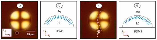
Figure 5.
LC droplet immobilized on the microchannel bottom under stationary flow conditions (a) with the assumed orientation of the mesophase molecules at the LC-water interface (b) and at the flow velocity of 5 mm/s (c) with the assumed orientation of the mesophase molecules at the LC-water interface (d). Red arrows demonstrate coordinate axes with respect to Figure 1. Crossed white arrows indicate positions of polarizers.
Under the stationary aqueous phase condition (Figure 5a), the cross texture is symmetrical and corresponds to the positions of polarizers. Figure 5b shows the respective assumed orientation of the mesophase molecules at the LC-water interface. Initiation of the aqueous phase flow leads to a deformed cross texture (Figure 5c). While the axial part of the cross remains virtually linear, its vertical part bends symmetrically along the flow. Figure 5d depicts such a deformed texture to the orientation of the mesophase molecules.
At flow velocities below ≈1–2 mm/s, microscopy images revealed no distinct deformation of the texture. A reliable and reproducible detection of the cross deformation was achieved at higher flow rates. The deformation angle β increased with the flow velocity and reduced with the droplet size. The angular deformation of the pattern and the sizes of droplets remained consistent at flowrates up to 40–50 mm/s. At higher flowrates, the cross texture transformed into a chaotic pattern, or a break-off of droplets occurred.
To obtain a quantitative correlation between the cross pattern deformation angle and flow velocities, we processed POM images of various-sized droplets in the range of flow rates up to 40 mm/s. Figure 6 summarizes the impact of the flow velocity on the deformation angle β for droplets with a diameter in the range of 20 to 60 μm.
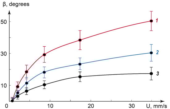
Figure 6.
The impact of the flow velocity on the deformation angle β. Approximate droplet diameters: 60 μm (1), 30 μm (2), and 20 μm (3).
Figure 6 shows that the deformation angle increases with the flow velocity for all the studied droplet sizes and decreases with the droplet diameter. The curves were successfully approximated by a logarithmic fitting with correlation coefficients of 0.96–0.99 (higher for larger droplets). The respective logarithmic functions can be summarized into the equation, which predicts the deformation angle values at different flow velocities:
where β is the deformation angle, k is the coefficient, which depends on the droplet size, U is the flow velocity, and U0 is the threshold flow velocity that initiates the deformation of the cross texture. For all the studied droplet sizes, U0 ≈ 1–1.5 mm/s. The coefficient k decreased with the droplet size.
Equation (3) characterizes the flow velocity in the microchannel in the range of dozens of mm/s by the deformation angle of the immobilized liquid crystal droplet texture in polarized light. It utilizes the behavior of the dispersed LC phase on the surface of a microchannel.
4. Discussion
The flows of nematic liquid crystals studied in this work are typical examples of smart materials. They respond to an applied stimulus (varying flow velocity) by changing their ordering behavior and the resulting transmission of polarized light through a microchannel. The optical properties of microchannels depend, therefore, on the behavior of a microscale layer of a continuous or dispersed LC phase on microchannel internal surfaces.
The main advantage of microfluidics over processing liquid crystal phases in macroscopic conditions is that microchannels allow for the generation of ordered single-phase or multiple-phase flows of liquid crystals by controlling only the parameters of infusion. Microchannels with high surface-to-volume ratios make interfacial effects predominant in determining the properties of confined liquid crystal systems. The size ranges of microscale liquid crystal phase domains are comparable to the characteristic sizes of microfluidic channels. In microfluidic confinement, therefore, stable and ordered domains of oriented mesophase can emerge near microchannel walls or at liquid-liquid interfaces.
Homeotropic alignment of the liquid crystal molecules near microchannel walls can create a microscale “coating” of mesophase. This microlayer turns out to be extremely sensitive to flow velocities starting from several μm/s, so even the smallest flow in such microchips is detectable. Further transitions from homeotropic to planar states allow us to characterize flow velocities in the range of hundreds of μm/s. Finally, droplets of mesophase deposited on the microchannel’s bottom surface offer a quantitative detection of flow velocities up to dozens of mm/s. Altogether, these effects show potential for designing microfluidic sensors suitable for flow characterization in low- or high-velocity ranges by using a simple polarized optical microscopy method without additional analytical tools.
Such a simple flow characterization can be useful for developing microfluidic devices with LC droplets immobilized in microfluidic traps on microchannel surfaces. Microtraps are successfully used to immobilize microscale objects such as living cells on surfaces of microchannels [70,71]. Another applied approach is to incorporate LC droplets into polymer shells. Flow-focusing microfluidics is a convenient tool to create such shells around droplets [56]. LC droplets in traps or polymer shells are potentially more convenient for flow sensing. Angular deformation of the “Maltese Cross” pattern from such small droplets can be used for a simple flow velocity characterization to track the performance of lab-on-chip tools, microfluidic logic devices, or organ-on-chip prototypes.
In this work, however, the focus was on a fundamental analysis of the revealed liquid crystal orientation behavior in microfluidic confinement. Future research can be highlighted in this respect. It is planned to perform more application-oriented studies concerning the immobilization of droplets in PDMS traps on microchannel surfaces to turn them into more stable velocity sensors. Future research shall include studying the impact of temperature on the orientation behavior of continuous and dispersed LC phases in confinement, characterizing the orientation behavior of LC droplets’ microfluidic traps, and additional numerical simulations of two-phase LC-water flows.
5. Conclusions
Microfluidic flows of liquid crystals demonstrate flow rate-controlled orientation behavior at liquid-wall and liquid-liquid interfaces. A reversible transition from a homeotropic alignment to a planar alignment can be set at flow velocities from approximately 50 µm/s to 5 mm/s at microfluidic LC-wall and LC-water interfaces in continuous phases, or two-phase threads. In channel-wide liquid crystal droplets, a chaotic convective pattern of domains developed after droplet break-up. Smaller droplets demonstrate a “Maltese Cross” alignment pattern at the interface between liquid crystal and aqueous medium. A quantitative correlation was found between the geometry of this pattern and the flow velocity up to 40 mm/s.
The studied single-phase and two-phase LC systems on surfaces of microchannels offer the potential for the quantitative characterization of flow velocities in a broad range of operation models of microfluidic devices. Such confined layers and droplets of nematic liquid crystals can be components of flow-sensitive coatings for future applications in laboratory-on-chip analytical tools.
Author Contributions
Conceptualization, Y.G. and A.B.; methodology, Y.G.; software, A.B.; validation, Y.G. and A.B.; formal analysis, Y.G.; investigation, A.B.; resources, Y.G.; data curation, A.B.; writing—original draft preparation, A.B.; writing, Y.G.; visualization, A.B.; supervision, Y.G. All authors have read and agreed to the published version of the manuscript.
Funding
This research received no external funding.
Institutional Review Board Statement
Not applicable.
Informed Consent Statement
Not applicable.
Data Availability Statement
Not applicable.
Acknowledgments
The study was carried out using the equipment of the Center for Collective Use “Nanomaterials and Nanotechnology” of Kazan National Research Technological University.
Conflicts of Interest
The authors declare no conflict of interest.
References
- Votava, M.; Ravoo, B.J. Principles and applications of cyclodextrin liquid crystals. Chem. Soc. Rev. 2021, 50, 10009–10024. [Google Scholar] [CrossRef]
- Shang, Y.; Wang, J.; Ikeda, T.; Jiang, L. Bio-inspired liquid crystal actuator materials. J. Mater. Chem. C 2019, 7, 3413–3428. [Google Scholar] [CrossRef]
- Wen, Z.; Yang, K.; Raquez, J.M. A review on liquid crystal polymers in free-standing reversible shape memory materials. Molecules 2020, 25, 1241. [Google Scholar] [CrossRef]
- Zhang, W.; Lub, J.; Schenning, A.P.H.J.; Zhou, G.; de Haan, L.T. Polymer Stabilized Cholesteric Liquid Crystal Siloxane for Temperature-Responsive Photonic Coatings. Int. J. Mol. Sci. 2020, 21, 1803. [Google Scholar] [CrossRef]
- Belmonte, A.; Pilz da Cunha, M.; Nickmans, K.; Schenning, A.P.H.J. Brush-Paintable, Temperature and Light Responsive Triple Shape-Memory Photonic Coatings Based on Micrometer-Sized Cholesteric Liquid Crystal Polymer Particles. Adv. Opt. Mater. 2020, 8, 2000054. [Google Scholar] [CrossRef]
- Chen, H.Q.; Wang, X.Y.; Bisoyi, H.K.; Chen, L.J.; Li, Q. Liquid Crystals in Curved Confined Geometries: Microfluidics Bring New Capabilities for Photonic Applications and beyond. Langmuir 2021, 37, 3789–3807. [Google Scholar] [CrossRef]
- Deng, J.; Han, D.; Yang, J. Applications of microfluidics in liquid crystal-based biosensors. Biosensors 2021, 11, 385. [Google Scholar] [CrossRef]
- Khan, M.; Liu, S.; Qi, L.; Ma, C.; Munir, S.; Yu, L.; Hu, Q. Liquid crystal-based sensors for the detection of biomarkers at the aqueous/LC interface. TrAC Trends Anal. Chem. 2021, 144, 116434. [Google Scholar] [CrossRef]
- Gollapelli, B.; Rama Raju Ganji, S.; Kumar Tatipamula, A.; Vallamkondu, J. Bio-derived chlorophyll dye doped cholesteric liquid crystal films and microdroplets for advanced anti-counterfeiting security labels. J. Mol. Liq. 2022, 363, 119952. [Google Scholar] [CrossRef]
- Gollapelli, B.; Suguru Pathinti, R.; Vallamkondu, J. Carbon Quantum Dots doped Cholesteric Liquid Crystal Films and Microdroplets for Anti-Counterfeiting. ACS Appl. Nano Mater. 2022, 5, 11912–11922. [Google Scholar] [CrossRef]
- Yang, T.; Yuan, D.; Liu, W.; Zhang, Z.; Wang, K.; You, Y.; Ye, H.; de Haan, L.T.; Zhang, Z.; Zhou, G. Thermochromic Cholesteric Liquid Crystal Microcapsules with Cellulose Nanocrystals and a Melamine Resin Hybrid Shell. ACS Appl. Mater. Interfaces 2022, 14, 4588–4597. [Google Scholar] [CrossRef] [PubMed]
- Mochalov, K.; Bobrovsky, A.; Solovyeva, D.; Samokhvalov, P.; Nabiev, I.; Oleinikov, V. Microstructure and optical properties of composites consisting of nanoporous stretched polypropylene doped with liquid crystals and quantum dots at a high concentration. Orient. J. Chem. 2016, 32, 2863–2872. [Google Scholar] [CrossRef]
- Pandey, S.; Vimal, T.; Singh, D.P.; Gupta, S.K.; Mahamuni, S.; Srivastava, A.; Manohar, R. Analysis of physical parameters and collective dielectric relaxations in core/shell quantum dot ferroelectric liquid crystal composite. J. Mol. Liq. 2015, 211, 157–163. [Google Scholar] [CrossRef]
- Osipova, V.V.; Kurilov, A.D.; Galyametdinov, Y.G.; Muravsky, A.A.; Kumar, S.; Chausov, D.N. Optical Properties of Nematic Liquid Crystal Composites with Semiconducting Quantum Dots. Zhidkie Krist. I Ikh Prakt. Ispol’zovanie 2020, 20, 84–92. [Google Scholar] [CrossRef]
- Liu, D.; Broer, D.J. Surface dynamics and mechanics in liquid crystal polymer coatings. In Proceedings of the SPIE—The International Society for Optical Engineering, San Francisco, CA, USA, 7–12 February 2015. [Google Scholar]
- Fuh, A.Y.G.; Chen, K.N.; Wu, S.T. Smart electro-optical iris diaphragm based on liquid crystal film coating with photoconductive polymer of poly(N-vinylcarbazole). Appl. Opt. 2016, 55, 6034–6039. [Google Scholar] [CrossRef]
- Yoon, H.J.; Lee, D.; Yang, J.; Song, J.K. Self-aligned liquid crystal smart windows with dual modes. J. Mol. Liq. 2022, 348, 118014. [Google Scholar] [CrossRef]
- Kurylo, I.; van der Tol, J.; Colonnese, N.; Broer, D.J.; Liu, D. Photo-responsive liquid crystal network-based material with adaptive modulus for haptic application. Sci. Rep. 2022, 12, 19512. [Google Scholar] [CrossRef]
- Kurilov, A.D.; Chausov, D.N.; Osipova, V.V.; Kucherov, R.N.; Belyaev, V.V.; Galyametdinov, Y.G. Highly luminescent nanocomposites of nematic liquid crystal and hybrid quantum dots CdSe/CdS with ZnS shell. J. Mol. Liq. 2021, 339, 116747. [Google Scholar] [CrossRef]
- Sengupta, A. Topological microfluidics: Present and prospects. Liq. Cryst. Today 2015, 24, 70–80. [Google Scholar] [CrossRef]
- Kim, J.-W.; Oh, Y.; Lee, S.; Kim, S.-H. Thermochromic Microcapsules Containing Chiral Mesogens Enclosed by Hydrogel Shell for Colorimetric Temperature Reporters. Adv. Funct. Mater. 2022, 32, 2107275. [Google Scholar] [CrossRef]
- Sengupta, A.; Tkalec, U.; Ravnik, M.; Yeomans, J.M.; Bahr, C.; Herminghaus, S. Liquid crystal microfluidics for tunable flow shaping. Phys. Rev. Lett. 2013, 110, 048303. [Google Scholar] [CrossRef] [PubMed]
- Sevim, S.; Sorrenti, A.; Franco, C.; Furukawa, S.; Pané, S.; Demello, A.J.; Puigmartí-Luis, J. Self-assembled materials and supramolecular chemistry within microfluidic environments: From common thermodynamic states to non-equilibrium structures. Chem. Soc. Rev. 2018, 47, 3788–3803. [Google Scholar] [CrossRef] [PubMed]
- Zhang, L.; Chen, Q.; Ma, Y.; Sun, J. Microfluidic Methods for Fabrication and Engineering of Nanoparticle Drug Delivery Systems. ACS Appl. Bio Mater. 2020, 3, 107–120. [Google Scholar] [CrossRef]
- Seiffert, S. Microfluidics and Macromolecules: Top-Down Analytics and Bottom-Up Engineering of Soft Matter at Small Scales. Macromol. Chem. Phys. 2017, 218, 1600280. [Google Scholar] [CrossRef]
- Cohen, C.; Giles, R.; Sergeyeva, V.; Mittal, N.; Tabeling, P.; Zerrouki, D.; Baudry, J.; Bibette, J.; Bremond, N. Parallelised production of fine and calibrated emulsions by coupling flow-focusing technique and partial wetting phenomenon. Microfluid. Nanofluid. 2014, 17, 959–966. [Google Scholar] [CrossRef]
- Gwon, S.; Park, S. Preparation of uniformly sized interpenetrating polymer network polyelectrolyte hydrogel droplets from a solid-state liquid crystal shell. J. Ind. Eng. Chem. 2021, 99, 235–245. [Google Scholar] [CrossRef]
- Dreyfus, R.; Tabeling, P.; Willaime, H. Ordered and Disordered Patterns in Two-Phase Flows in Microchannels. Phys. Rev. Lett. 2003, 90, 4. [Google Scholar] [CrossRef]
- Zilio, C.; Sola, L.; Damin, F.; Faggioni, L.; Chiari, M. Universal hydrophilic coating of thermoplastic polymers currently used in microfluidics. Biomed. Microdevices 2014, 16, 107–114. [Google Scholar] [CrossRef]
- Babaei, M.; Bonakdar, S.; Nasernejad, B. Selective biofunctionalization of 3D cell-imprinted PDMS with collagen immobilization for targeted cell attachment. Sci. Rep. 2022, 12, 1–9. [Google Scholar]
- Wu, T.; Suzuki, H.; Su, Y.; Tang, Z.; Zhang, L.; Yomo, T. Bio-inspired three-dimensional self-patterning of functional coatings for PDMS microfluidics. Soft Matter 2013, 9, 3473–3477. [Google Scholar] [CrossRef]
- Shakeri, A.; Imani, S.M.; Chen, E.; Yousefi, H.; Shabbir, R.; Didar, T.F. Plasma-induced covalent immobilization and patterning of bioactive species in microfluidic devices. Lab Chip 2019, 19, 3104–3115. [Google Scholar] [CrossRef] [PubMed]
- Ohashi, T.; Mawatari, K.; Kitamori, T. On-chip antibody immobilization for on-demand and rapid immunoassay on a microfluidic chip. Biomicrofluidics 2010, 4, 032207. [Google Scholar] [CrossRef]
- Liu, T.; Yin, Y.; Yang, Y.; Russell, T.P.; Shi, S. Layer-by-Layer Engineered All-Liquid Microfluidic Chips for Enzyme Immobilization. Adv. Mater. 2022, 34, 2105386. [Google Scholar] [CrossRef] [PubMed]
- Schröder, H.; Hoffmann, L.; Müller, J.; Alhorn, P.; Fleger, M.; Neyer, A.; Niemeyer, C.M. Addressable microfluidic polymer chip for DNA-directed immobilization of oligonucleotide-tagged compounds. Small 2009, 5, 1547–1552. [Google Scholar] [CrossRef] [PubMed]
- Sengupta, A.; Tkalec, U.; Bahr, C. Nematic textures in microfluidic environment. Soft Matter 2011, 7, 6542–6549. [Google Scholar] [CrossRef]
- Čopar, S.; Kos, Ž.; Emeršič, T.; Tkalec, U. Microfluidic control over topological states in channel-confined nematic flows. Nat. Commun. 2020, 11, 59. [Google Scholar] [CrossRef]
- Sengupta, A.; Herminghaus, S.; Bahr, C. Liquid crystal microfluidics: Surface, elastic and viscous interactions at microscales. Liq. Cryst. Rev. 2014, 2, 73–110. [Google Scholar] [CrossRef]
- Wiese, O.; Marenduzzo, D.; Henrich, O. Microfluidic flow of cholesteric liquid crystals. Soft Matter 2016, 12, 9223–9237. [Google Scholar] [CrossRef]
- Anderson, T.G.; Mema, E.; Kondic, L.; Cummings, L.J. Transitions in Poiseuille flow of nematic liquid crystal. Int. J. Non-Linear Mech. 2015, 75, 15–21. [Google Scholar] [CrossRef]
- Takenaka, Y.; Škarabot, M.; Muševič, I. Nematic Liquid-Crystal Necklace Structure Made by Microfluidics System. Langmuir 2020, 36, 3234–3241. [Google Scholar] [CrossRef]
- Copar, S.; Ravnik, M.; Žumer, S. Introduction to colloidal and microfluidic nematic microstructures. Crystals 2021, 11, 956. [Google Scholar] [CrossRef]
- Śliwa, I.; Maslennikov, P.V.; Zakharov, A.V. Two shear driven flow regimes in microfluidic nematic devices: Tumbling and laminar. J. Mol. Liq. 2021, 340, 117205. [Google Scholar] [CrossRef]
- Shojaei-Zadeh, S.; Anna, S.L. Role of surface anchoring and geometric confinement on focal conic textures in smectic-a liquid crystals. Langmuir 2006, 22, 9986–9993. [Google Scholar] [CrossRef]
- Sargazi, M.; Linford, M.R.; Kaykhaii, M. Liquid Crystals in Analytical Chemistry: A Review. Crit. Rev. Anal. Chem. 2019, 49, 243–255. [Google Scholar] [CrossRef]
- Wang, H.; Xu, T.; Fu, Y.; Wang, Z.; Leeson, M.S.; Jiang, J.; Liu, T. Liquid Crystal Biosensors: Principles, Structure and Applications. Biosensors 2022, 12, 639. [Google Scholar] [CrossRef] [PubMed]
- Xu, Y.; Rather, A.M.; Yao, Y.; Fang, J.-C.; Mamtani, R.S.; Bennett, R.K.A.; Atta, R.G.; Adera, S.; Tkalec, U.; Wang, X. Liquid crystal—Based open surface microfluidics manipulate liquid mobility and chemical composition on demand. Sci. Adv. 2021, 7, eabi7607. [Google Scholar] [CrossRef] [PubMed]
- Chen, W.; Shao, F.; Xianyu, Y. Microfluidics-Implemented Biochemical Assays: From the Perspective of Readout. Small 2020, 16, 1903388. [Google Scholar] [CrossRef]
- Fan, Y.-J.; Chen, F.-L.; Liou, J.-C.; Huang, Y.-W.; Chen, C.-H.; Hong, Z.-Y.; Lin, J.-D.; Hsiao, Y.-C. Label-Free Multi-Microfluidic Immunoassays with Liquid Crystals on Polydimethylsiloxane Biosensing Chips. Polymers 2020, 12, 395. [Google Scholar] [CrossRef]
- Wang, I.-T.; Lee, Y.-H.; Chuang, E.-Y.; Hsiao, Y.-C. Sensitive, Color-Indicating and Labeling-Free Multi-Detection Cholesteric Liquid Crystal Biosensing Chips for Detecting Albumin. Polymers 2021, 13, 1463. [Google Scholar] [CrossRef]
- Gollapelli, B.; Tatipamula, A.K.; Dewanjee, S.; Pathinti, R.S.; Vallamkondu, J. Detection of bile acids using optical biosensors based on cholesteric liquid crystal droplets. J. Mater. Chem. C 2021, 9, 13991–14002. [Google Scholar] [CrossRef]
- Bao, P.; Paterson, D.A.; Harrison, P.L.; Miller, K.; Peyman, S.; Jones, J.C.; Sandoe, J.; Evans, S.D.; Bushby, R.J.; Gleeson, H.F. Lipid coated liquid crystal droplets for the on-chip detection of antimicrobial peptides. Lab Chip 2019, 19, 1082–1089. [Google Scholar] [CrossRef] [PubMed]
- Jang, J.-H.; Park, S.-Y. pH-responsive cholesteric liquid crystal double emulsion droplets prepared by microfluidics. Sens. Actuators B Chem. 2017, 241, 636–643. [Google Scholar] [CrossRef]
- Hamlington, B.D.; Steinhaus, B.; Feng, J.J.; Link, D.; Shelley, M.J.; Shen, A.Q. Liquid crystal droplet production in a microfluidic device. Liq. Cryst. 2007, 34, 861–870. [Google Scholar] [CrossRef]
- Priest, C.; Quinn, A.; Postma, A.; Zelikin, A.N.; Ralston, J.; Caruso, F. Microfluidic polymer multilayer adsorption on liquid crystal droplets for microcapsule synthesis. Lab Chip 2008, 8, 2182–2187. [Google Scholar] [CrossRef]
- Xu, S.; Nisisako, T. Polymer Capsules with Tunable Shell Thickness Synthesized via Janus-to-core shell Transition of Biphasic Droplets Produced in a Microfluidic Flow-Focusing Device. Sci. Rep. 2020, 10, 4549. [Google Scholar] [CrossRef] [PubMed]
- Zana, R. Dynamics of Surfactant Self-Assemblies; CRC Press: Boca Raton, FL, USA, 2019; p. 537. [Google Scholar]
- McDonald, J.C.; Duffy, D.C.; Anderson, J.R.; Chiu, D.T.; Wu, H.; Schueller, O.J.A.; Whitesides, G.M. Fabrication of microfluidic systems in poly(dimethylsiloxane). Electrophoresis 2000, 21, 27–40. [Google Scholar] [CrossRef]
- Anna, S.L.; Bontoux, N.; Stone, H.A. Formation of dispersions using “flow focusing” in microchannels. Appl. Phys. Lett. 2003, 82, 364–366. [Google Scholar] [CrossRef]
- Link, D.R.; Anna, S.I.; Weitz, D.A.; Stone, H.A. Geometrically Mediated Breakup of Drops in Microfluidic Devices. Phys. Rev. Lett. 2004, 92, 545031–545034. [Google Scholar] [CrossRef]
- Christopher, G.F.; Anna, S.L. Microfluidic methods for generating continuous droplet streams. J. Phys. D Appl. Phys. 2007, 40, R319–R336. [Google Scholar] [CrossRef]
- Anna, S.L. Droplets and Bubbles in Microfluidic Devices. Annu. Rev. Fluid Mech. 2016, 48, 285–309. [Google Scholar] [CrossRef]
- Sarman, S.; Wang, Y.-L.; Laaksonen, A. Non-Newtonian rheological properties of shearing nematic liquid crystal model systems based on the Gay–Berne potential. Phys. Chem. Chem. Phys. 2015, 17, 16615–16623. [Google Scholar] [CrossRef] [PubMed]
- Crespo, M.; Majumdar, A.; Ramos, A.M.; Griffiths, I.M. Solution landscapes in nematic microfluidics. Phys. D Nonlinear Phenom. 2017, 351–352, 1–13. [Google Scholar] [CrossRef]
- Bezrukov, A.N.; Osipova, V.V.; Galyametdinov, Y.G. Orientational behavior of a nematic liquid crystal and its composite with quantum dots in a microfluidic channel. Russ. Chem. Bull. 2022, 71, 2092–2097. [Google Scholar] [CrossRef]
- Song, H.; Chen, D.L.; Ismagilov, R.F. Reactions in droplets in microfluidic channels. Angew. Chem. Int. Ed. Engl. 2006, 45, 7336–7356. [Google Scholar] [CrossRef] [PubMed]
- Ng, K.C.; Hwang, Y.H.; Sheu, T.W.H.; Yusoff, M.Z. A Numerically Consistent Multiphase Poiseuille Flow Computation by a New Particle Method. J. Teknol. 2015, 76, 83–87. [Google Scholar] [CrossRef]
- Shi, H.; Huang, Y. A GPU-Based δ-Plus-SPH Model for Non-Newtonian Multiphase Flows. Water 2022, 14, 1734. [Google Scholar] [CrossRef]
- Zainali, A.; Tofighi, N.; Shadloo, M.S.; Yildiz, M. Numerical investigation of Newtonian and non-Newtonian multiphase flows using ISPH method. Comput. Methods Appl. Mech. Eng. 2013, 254, 99–113. [Google Scholar] [CrossRef]
- Sinha, N.; Yang, H.; Janse, D.; Hendriks, L.; Rand, U.; Hauser, H.; Köster, M.; van de Vosse, F.N.; de Greef, T.F.A.; Tel, J. Microfluidic chip for precise trapping of single cells and temporal analysis of signaling dynamics. Commun. Eng. 2022, 1, 18. [Google Scholar] [CrossRef]
- Narayanamurthy, V.; Nagarajan, S.; Firus Khan, A.A.Y.; Samsuri, F.; Sridhar, T.M. Microfluidic hydrodynamic trapping for single cell analysis: Mechanisms, methods and applications. Anal. Methods 2017, 9, 3751–3772. [Google Scholar] [CrossRef]


Disclaimer/Publisher’s Note: The statements, opinions and data contained in all publications are solely those of the individual author(s) and contributor(s) and not of MDPI and/or the editor(s). MDPI and/or the editor(s) disclaim responsibility for any injury to people or property resulting from any ideas, methods, instructions or products referred to in the content. |
© 2023 by the authors. Licensee MDPI, Basel, Switzerland. This article is an open access article distributed under the terms and conditions of the Creative Commons Attribution (CC BY) license (https://creativecommons.org/licenses/by/4.0/).