Abstract
The interfacial designing of carbon fiber (CF)/epoxy composites, as a well-accepted method used to obtain high-performance composites, has gained extensive attention. However, an improvement in interfacial adhesion is usually accompanied by a simultaneous decrease in toughness, which has become an obstacle to the performance enhancement of CF/epoxy composites. Herein, nanosized UiO-66-NH2 was proposed to yield on the CF surface through an in situ growth method for preparing high-performance CF/epoxy composites. The induced UiO-66-NH2 could significantly enhance the active groups, surface roughness and wettability on the fiber surface, which can be confirmed by XPS, FTIR, dynamic contact angle (DCA) and SEM. Moreover, the porous structure of UiO-66-NH2 enables the epoxy resin to pass through it, which could toughen the matrix by forming an interpenetrating network structure and reducing the density of resin crosslinking. Meanwhile, the size effect of UiO-66-NH2 could hinder the crack propagation and release the stress concentration. Benefiting from these interfacial strengthening and toughening effects, the interlaminar shear strength and impact strength increased by 44.2% and 27.6%, respectively, in comparison to those of untreated CF. This work proposes a simple and effective strategy for interfacial designing that could offer new ideas for solving the conflict between the strengthening and toughening and provide a practical basis for preparing high-performance resin matrix composites.
1. Introduction
In view of their extraordinary properties, such as the high specific strength and modulus, thermal stability and corrosion resistance, carbon fiber (CF)-reinforced composites have made a considerable impact on many fields [1,2]. However, on account of the high graphitization degree of chemically inert graphite microcrystalline in the CF cortex, the poor activity of the CF leads to a weak reinforced efficiency, which directly affects the interface bonding between the CF and resin matrix [3]. Therefore, some strategies for the surface modification of CFs need to be adopted to improve the compatibility between the fiber and the matrix so as to obtain high-performance CF epoxy composites [4,5].
In recent years, grafting nanotubes, nanowires and other nanomaterials onto the CF surface has been an effective strategy devoted to strengthening the carbon fiber composites, which can realize the multi-scale enhancement of composite materials [6,7,8]. However, due to the randomness of the group reaction, the grafting effect of nanoparticles is difficult to control [9,10]. Meanwhile, Wang et al. [11] pointed out that, when the grafting density is too high, the narrow gap among the nanoparticles would inhibit the flow of the resin matrix on the CF surface. Moreover, the excessive bonding at the interface would cause the interfacial bonding strength to be too strong and the resin cross-linking density to increase, resulting in a decrease in the toughness of the composite [12,13]. Therefore, an effective strategy for synergistically enhancing the strength and toughness is still demanded in the interfacial modification and practical application of CF composites.
Metal–organic frameworks (MOFs) with a high designability have shown potential application value in catalysis, gas adsorption and sensors [14,15,16,17]. Recently, MOFs have been reported to regulate the performance of epoxy composites on account of their large specific surface area, controllable pore size and abundant active groups [18,19]. Jian et al. [20] prepared zinc borate@ZIF-8 core–shell nanorods, which exhibited a 20% improvement in the tensile strength of the composites. Ma et al. [21] grew Sn-MOF on PANI nanorods, and this novel nanoarchitecture significantly improved the fire safety and mechanical property of epoxy resin. Among these MOF materials, UiO66-NH2, which is the representative Zr-based MOF, presented more distinguished mechanical properties and a greater structural stability than other MOFs due to the high coordination number of its structure [22,23]. Ramezanzadeh et al. [24] covalently attached GMA onto UiO66-NH2 nanoparticles, and the thermal stability improved by 80% when the content of GMA-UiO-66 was 0.2 wt.% in epoxy resin. The nanoparticles also showed a good tensile performance, manifesting that the GMA-UiO-66 could toughen the resin effectively. Therefore, it is worth considering that employing UiO66-NH2 to modify the CF surface could be an effective strategy for reinforcing the interfacial properties. On the one hand, introducing UiO66-NH2 into the interface can significantly increase the roughness and polarity of the surface of carbon fiber, resulting in good mechanical interlocking and infiltration between the CF and resin, thus promoting the improvement in the interface properties and the overall properties of the material. Meanwhile, the activity groups in its structure can provide more reaction sites and form a large number of chemical and hydrogen bonds with the resin matrix, which participate in the curing process of the resin matrix and play a strengthening role [25,26]. On the other hand, Hu et al. proved that the porous structure of UiO66-NH2 enables the epoxy resin to pass through it, which could toughen the matrix by forming an interpenetrating network structure and reducing the density of resin crosslinking [27]. In accordance with the above two aspects, the exploration of the regulation and strengthening mechanism of such interfacial reinforcement materials would be conducive to preparing the high-performance CF/epoxy composites and expanding the application of MOFs in the field of CF composite materials, which is of great practical significance [28,29].
In this paper, UiO66-NH2 nanoparticles as the interphase were constructed on the CF surface using the solvothermal method in order to achieve a synergistic enhancement in the strength and toughness of carbon fiber composites. To investigate the effects of MOF growth on the performance of the composites, the chemical composition, wettability and interfacial properties, combined with the mechanical properties of the modified CFs and their composites, were deeply explored to clarify its strengthening and toughening mechanism. In general, this study provides a promising strategy for fabricating advanced CF/epoxy composites for their application in the transportation and aerospace industries.
2. Materials and Methods
2.1. Materials
Carbon fibers (3K, diameter 7 μm, linear density 198 mg·m−1) were purchased from Zhongfu Shenying Carbon Fiber Co., Ltd. (Lianyungang, China). Zirconium chloride (ZrCl4) and 2-aminoterephthalic acid (C8H7NO4) were obtained from Shanghai Macklin Biochemical Co., Ltd. (Shanghai, China). N,N-dimethylformamide (DMF), and glacial acetic acid (CH3COOH) were provided by Sinopharm Chemical Reagent Co., Ltd. (Shanghai, China). Curing agent (H-256, 3,3-diethyl 4,4-diaminodiphenylmethane) was obtained from Hubei Jusheng Technology Co., Ltd. (Tianmen, China). Epoxy resin (E-51) was received from Wuxi resin factory (Wuxi, China).
2.2. Fabrication of MOF/CF
The CFs were refluxed with acetone in a Soxhlet extractor for 48 h to remove the sizing agent and impurities on the fiber surface. The resulting fibers were denoted as CF-COOH since the fibers were acidized in the production process.
The MOF/CF was prepared as follows. Firstly, zirconium chloride (ZrCl4) (1 mmol) was dissolved in 40 mL DMF. Then, 2-aminoterephthalic acid (1 mmol) was added and stirred for 1 h. Subsequently, various volume of acetic acid (5, 7, 9, 11 mL) were added. Finally, appropriate amount of CF-COOH was immersed into the above solution and transferred together into the autoclave reacting for 24 h at 80 °C. After cooling to room temperature, the modified CFs were taken out and washed repeatedly with DMF. After drying at 80 °C overnight, the obtained fibers were denoted as MOF/CF-5, MOF/CF-7, MOF/CF-9 and MOF/CF-11, respectively, according to the different volume of acetic acid. The manufacturing process of MOF/CF multi-scale reinforcement is shown in Figure 1.
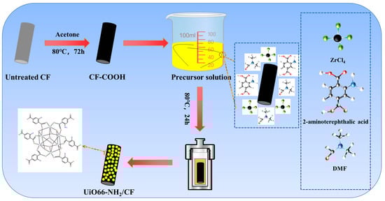
Figure 1.
Illustration of the manufacturing process of MOF/CF multi-scale reinforcement.
2.3. Preparation of MOF/CF Epoxy Composites
MOF/CF-reinforced epoxy composites were prepared by hot-molding method. First, the epoxy resin and curing agent were mixed with a mass ratio of 25:8. Then, the modified fibers were fully infiltrated with epoxy resin system, and the resin content of composites was controlled at 35 ± 1.5%. After preheating the mold at 90 °C, the infiltrated CFs were placed. The mold was first heated to 90 °C and cured at 5 MPa for 2 h. The second stage was heated to 120 °C and cured at 10 MPa for 2 h, which was followed by heating to 150 °C and maintaining for 3 h.
2.4. Characterization
The functional groups and chemical bonds of CFs were analyzed by Fourier transform infrared spectroscopy (FTIR, VECTOR-22, Bruker, Billerica, MA, USA) of Bruker Company. The surface elements of UiO66-NH2/CF were investigated by X-ray electron spectroscopy (XPS) of VG (Manchester, UK) in the United Kingdom. Scanning electron microscopy (SEM, FEI Verios 460 and TESCAN VEGA3, Lausanne, Switzerland) was employed to inspect the surface morphologies and fracture surface of the CFs and composites. To prepare the SEM sample, the CFs and the composites were fixed on the copper sheet with conductive tape, and then 60~120 s gold spray treatment was carried out.
The wettability of CFs was estimated by a dynamic contact angle meter and tensiometer (DCAT21, Data Physics Instruments, Stuttgart, Germany). According to the following equation, the surface energy dispersion component and polar component of CFs can be calculated:
where l, and are the surface energy of liquid and its dispersion and polar component, respectively.
Interlaminar shear strength (ILSS) is the strength limit under interlaminar shear loading and is used to evaluate the interlaminar properties of composites. According to ASTM D2344 standard [30], the ILSS of MOF/CF composites was determined on an electronic universal testing machine with the three-point test method. The sample dimensions were 25 mm × 6 mm × 2 mm, the cross-head speed was 1 mm/min and the values of ILSS were calculated according to the following equation, which was averaged from 6 valid results of each sample:
where F was the maximum load (N) and b and h were the width (mm) and height (mm) of the sample, respectively.
According to ASTM D7136 [31], the impact toughness of composites was performed on a drop-weight impact testing machine (9250HV) with an impact velocity of 2 m/s. The sample dimensions were 55 mm × 6 mm × 2 mm and the final result of each sample was averaged from 6 valid results.
3. Results
3.1. Surface Chemical Composition Analysis of MOF/CF
Figure 2 shows the FTIR spectrum of CF-COOH, MOF/CF-5~11. For CF-COOH, the stretching vibration peaks of -OH and -C=O in -COOH lied in 3440 and 1630 cm−1 respectively can be observed. After growing UiO66-NH2, all MOF/CF samples still exhibit strong -C=O peak at 1630 cm−1. This may be due to the increased amount of carboxyl on the fiber surface arising from the 2-aminoterephthalic acid in UiO66-NH2; thus, a high intensity peak of C=O could be detected even though the modified CF surface was covered by the MOFs. In addition, some peaks differing from the features of CF-COOH obviously appeared. These peaks could be attributed to the induced MOF coating covering the CF-COOH surface. For example, it can be seen from the MOF/CF-5~11 spectrum that a wide peak appears at 3600–3100 cm−1, which was generated by the combination of -OH and -NH2 stretching vibrations, so the peak was significantly wider and the intensity of the peak increased compared to the spectrum of CF-COOH. The peak located at 1230 cm−1 can be ascribed to the stretching vibration of the C-N bond in UiO66-NH2. The peak at 570 cm−1 belonged to the Zr-(OC) asymmetric stretching vibration, implying the growth of UiO66-NH2 on the fiber surface. The above results confirmed that ZrCl4 successfully coordinated with 2-aminoterephthalic acid to form UiO66-NH2 on the surface of carbon fiber.
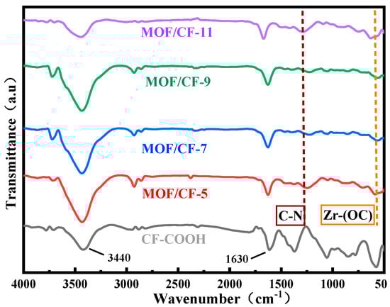
Figure 2.
FTIR of MOF/CF at different acid concentrations.
XPS was performed to further analyze the chemical composition of the fiber surface, and the corresponding results are summarized in Figure 3. For CF-COOH, the C1s and O1s can be observed at 284.6 and 532.1 eV, respectively (Figure 3a). After peak fitting, the C1s (Figure 3b) presented three binding energy peaks. The main peak at 284.5 eV can be assigned to the C-C bond in the CF structure. The peaks at 286.3 and 288.5 eV represent the C-O bond and the -COOH group resulting from the manufacturing process of CFs. Figure 3c–f show the wide-scan spectrum of the XPS of MOF/CF-9 and the peak-fitting curves. The functionalized CFs presented two extra peaks of N1s and Zr3d in Figure 3c, suggesting the growth of UiO66-NH2 on the fiber surface. Meanwhile, the C1s peak-fitted curve (Figure 3d) showed a new peak at 285.1 eV, which can be ascribed to the C-N bond in the UiO66-NH2 structure. After further peak fitting the N1s and Zr3d, the curves showed that the nitrogen element mainly exists as C-N bond (398.4 eV) and -N-H bond (399.2 eV) on the fiber surface (Figure 3e), and Zr has characteristic peaks at binding energy of 184.9 and 182.6 eV (Figure 3f), respectively, which are consistent with the chemical environment of N and Zr in the UiO66-NH2 structure. Combined with the SEM and XPS test results, it can be proved that UiO66-NH2 nanoparticles were successfully grown on the CF surface.

Figure 3.
XPS spectrum of carbon fiber surface elements and peak-fitting curves of C1s, N1s and Zr3d: (a,b) CF-COOH; (c–f) MOF/CF-9.
Figure 4 shows the X-ray diffraction (XRD) patterns of CF-COOH, MOF/CF-5~11. For CF-COOH, a feature peak located at 2θ = 25° corresponds to the (002) crystal plane in the graphite structure. For MOF/CF-5~11, on this basis, two distinct characteristic peaks located at 2θ = 7.4° and 8.4° can be found, representing the (111) and (002) crystal face diffraction of UiO66-NH2, respectively. Therefore, the XRD pattern of MOF/CF-5~11 also indicates that the UiO66-NH2 crystals were successfully in situ grown onto the surface of CF.
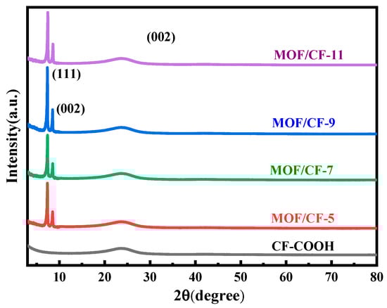
Figure 4.
XRD patterns of MOF/CF at different acid concentrations.
3.2. Surface Topography of MOF/CF
The surface topography of MOF/CF reinforcements was investigated by SEM, as shown in Figure 5. The surface topography of CF-COOH in Figure 5a was smooth after cleaning and there was no sizing agent residue. After in situ growing MOF, there were obvious polyhedral nanoparticles on the surface of MOF/CF-5~11 (Figure 5b–e). When the amount of acid was 5 mL (Figure 5b), although UiO66-NH2 particles were generated on the fiber surface, there were not enough to cover the fiber surface. For the case of MOF/CF-7 (Figure 5c), an increased amount of MOF particles on the fiber surface can be observed, but the distribution is still uneven. When the amount of acetic acid was 9 mL (Figure 5d), the UiO66-NH2 nanoparticles wrapped tightly onto the fiber surface and the morphology and particle size were relatively uniform. With an increase in the acid content, the amount of MOF on fiber surface increased significantly, which also caused serious agglomeration at the same time, as shown in Figure 5e. The distribution of nanoparticles at the interface directly affects the overall performance of the composite. A good distribution can promote the formation of a strong interface. In contrast, an uneven distribution could reduce the adhesion ability between the reinforcement and the matrix and increase the risk of interface disbonding and cracking, which can further affect the overall performance of the material.
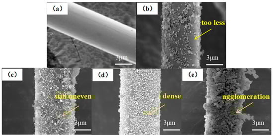
Figure 5.
SEM images of MOF/CF: (a) CF-COOH; (b) MOF/CF-5; (c) MOF/CF-7; (d) MOF/CF-9; (e) MOF/CF-11.
3.3. Wettability of MOF/CF
Figure 6 shows the effects of the surface modification UiO66-NH2 on the wettability of CFs. In Figure 6a, the contact angles of CF-COOH with water and diiodomethane are 67° and 42°, respectively. For MOF/CF, the contact angles between CF and two liquids decreased due to the increase in oxygen-containing functional groups (such as hydroxyl and amino groups) on the CF surface. When the amount of acetic acid was 9 mL, the contact angle of MOF/CF-9 was the lowest, which decreased to 40.5° and 32.4° in water and diiodomethane, respectively. The presence of MOF on the CF surface could enhance the surface roughness, which was conducive to the infiltration of water and diiodomethane, and the infiltration of fibers was more adequate. However, when acid was excessive, the agglomeration of MOF in an uneven distribution on the fiber surface was confirmed by SEM results, which could decrease the wettability and contact angle of the fibers.
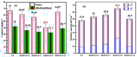
Figure 6.
Contact angles and surface energy of MOF/CF (a) contact angle; (b) surface energy.
The changes in the CF surface energy, as well as its dispersion component (γd) and polar component (γp), are summarized in Figure 6b. The surface energy of CF-COOH was relatively low at only 47.8 mN·m−1. After surface modification with MOF, the surface energy of all of the MOF/CF samples increased distinctly. This could be assigned to the enhanced amount of polar groups and the improvement in surface roughness after the incorporation of the UiO66-NH2 coating. For MOF/CF-9, the morphology and dispersion of UiO66-NH2 particles on the fiber surface were better than other samples, and the surface energy reached a maximum of 65.1 mN·m−1. In general, the higher the surface energy, the stronger the interfacial wettability between the reinforcement and the matrix, which was more conducive to forming a strong interface in the composites, thus improving the overall performance of the composite.
3.4. Interlaminar Shear Strength of MOF/CF Composites
The ILSS results of epoxy composites reinforced by CF-COOH and CF/MOF-5~11 are shown in Figure 7. For CF-COOH composites, the ILSS value was only 36 MPa. After the surface growth of UiO66-NH2, the ILSS values of MOF/CF composites increased by 26.7%, 36.1%, 44.2% and 23.3%, respectively, compared with CF-COOH. This might be because the UiO66-NH2 in the interfacial phase could significantly increase the surface roughness and polarity of the fibers, which greatly promoted the infiltration between the fibers and the matrix. Moreover, the -NH2 of UiO66-NH2 nanoparticles can not only generate a hydrogen bond with -COOH on CF, but can also participate in the curing process of the resin matrix and form a “bond bridge” between the fiber and resin. With the increase in acid content, the amount and dispersion of UiO66-NH2 on the fiber surface were significantly improved, so the interfacial bonding ability between the fiber and resin was gradually enhanced. Nevertheless, the ILSS of MOF/CF-11 exhibited a significant decline, which might be ascribed to the serious agglomeration of MOF particles and increase the risk of interfacial cracking.
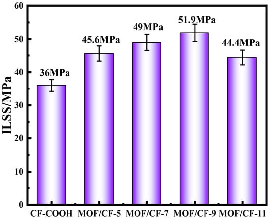
Figure 7.
Interlayer shear strength of MOF/CF epoxy composites.
The ILSS fracture morphologies of composites were further investigated, as presented in Figure 8. In the case of the CF-COOH composite (Figure 8a), markedly interfacial debonding can be observed, as well as no resin residue on the pulled-out fibers, indicating that the poor adhesion between the fiber and resin and the failure mode of the composite was mainly due to the interfacial adhesive failure. After UiO66-NH2 growth, the fracture morphology of MOF/CF-5 composites (Figure 8b) showed obvious residual resin on the CF surface and a shorter debonded fiber in comparison to CF-COOH, suggesting an improvement in the chemical and physical interaction between the CF and resin matrix. With an increase in the content of acetic acid, as shown in Figure 8c–e, the length of debonded fibers decreased and the resin remaining on the fiber surface gradually increased, implying the formation of a strengthening interphase. In particular, for MOF/CF-9 (Figure 8d), the fracture surface was more flat and the fibers were almost fully wrapped with the resin, which indicated that the UiO66-NH2 nanoparticles, as well as their morphology and dispersion state on the fiber surface, could considerably affect the interfacial adhesion between the fiber and resin. Meanwhile, the failure mode of the MOF/CF-reinforced composites was changed to a mix of interfacial adhesion failure and cohesive failure. Above all, the SEM images further provided evidence of the improved interfacial property of CF epoxy composites. It can be concluded that the flattest fracture surface is always accompanied by the strongest interfacial adhesion, thus leading to the highest ILSS value.
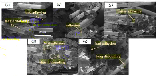
Figure 8.
Fracture morphology of CF composites (a) CF; (b) MOF/CF-5; (c) MOF/CF-7; (d) MOF/CF-9; (e) MOF/CF-11.
3.5. Impact Strength of MOF/CF Composites
The impact toughness of composites is presented in Figure 9. For CF-COOH composites, the impact strength was 64.9 kJ/m2 due to the poor interfacial adhesion. In general, the interfacial performance mainly affects the impact toughness of the composites. A weak interphase region could not effectively hinder the expansion of the crack, which resulted in the rapid propagation of the crack at the interface; thus, the composites would fracture under a relative low external load. After growing UiO66-NH2 on the CF surface, the impact resistance of the composites was enhanced, and MOF/CF-9 reached the highest impact strength, which was 27.6% higher than CF-COOH. Due to the introduction of a large number of polar amino groups, the infiltration between the fiber and resin was notably improved. Meanwhile, the size effect of MOF particles significantly improved the mechanical interlocking between the CF and resin, and the amino groups in MOF can participate in the curing process of resin. Therefore, the anchoring ability of the fiber to the resin matrix was improved, which helped to produce good interfacial bonding, improved the difficulty of interfacial cracking and increased the energy required during the cracking process [32].
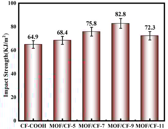
Figure 9.
Impact strength of MOF/CF epoxy composites.
In addition, UiO66-NH2 can also change the propagation direction of cracks by hindering the crack, inducing a continuous deflection of cracks and making the crack propagation path that is perpendicular to the axial direction of the fiber at first become complex. In this propagation process, the cracks were forced to split into more microcracks under the obstruction and induction of UiO66-NH2, and the initial energy dissipated so that the impact resistance of the composite improved [33].
To further confirm the above results, the fracture surface of the composites was inspected by SEM. In Figure 10a, significant debonding in the interphase can be observed, where the uneven surface remained. Moreover, the neat fracture surface of the resin also presented typical brittle fracture characteristics, indicating weak interfacial properties and a poor impact resistance. For MOF/CF-reinforced composites (Figure 10b–e), the fibers and resin were tightly bonded, suggesting an improved interfacial adhesion. In addition, for MOF/CF-9 in Figure 10d, the resin fracture surface was more rough in comparison to other samples and presented ductile fracture characteristics, suggesting that the matrix deformed greatly during the impact process. Due to the deflection and induction effect of UiO66-NH2 on cracks, a large number of microcracks gradually formed a wide range of network propagation paths in multiple directions. Under this propagation, the fibers broke with the resin to produce more debris [34]. Therefore, the rough matrix fracture surface might indicate a strong induction and dissipation ability of the crack at the interface. In general, this process of induction and dissipation could absorb more extra energy and force the composites to consume more applied load stress, further increasing the impact strength of the composites. Thus, the MOF/CF-9 exhibited the largest improvement in the impact strength.
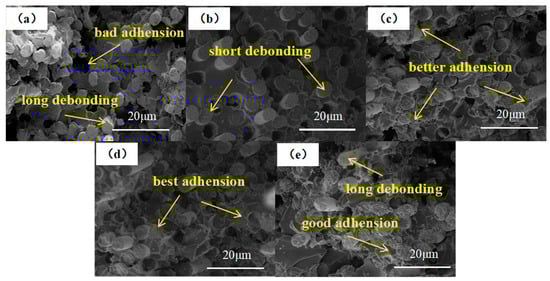
Figure 10.
Morphology of the impact fracture of composites: (a) CF-COOH; (b) MOF/CF-5; (c) MOF/CF-7; (d) MOF/CF-9; (e) MOF/CF-11.
4. Conclusions
In this paper, the multi-scale reinforcement MOF/CF was fabricated by in situ growing UiO66-NH2 on the surface of CFs to strengthen and toughen the epoxy composites. With the aid of acetic acid as a regulator, the UiO66-NH2 particles achieved a high-uniformity distribution on the CF surface. The surface energy of the MOF/CF reached 65.1 mN·m−1, which was improved by 36%. Meanwhile, the experimental results confirmed that UiO66-NH2 could promote the formation of good interfacial bonding between the CFs and resin matrix, and dissipate the applied stress at the interphase. Consequently, the interfacial and mechanical properties were notably enhanced. Compared with CF/EP, the ILSS and impact strength of the MOF/CF-reinforced composite were increased by 44.2% and 27.6%, respectively. Meanwhile, the impact fracture surface presented typical ductile fracture characteristics. Our study proved that this facile and effective process has great potential application in the manufacture of high-performance CF composites as the shell and structure parts. Moreover, this work promisingly indicates that the inherent characteristics of MOF could endow CFs with more applications, such as catalysts, capacitors and electromagnetic materials.
Author Contributions
M.Z. designed this experiment and revised the manuscript. Z.S. carried out the experiments, the characterization tests and wrote the manuscript. J.G. and Q.Q. carried out the characterization tests, analyzed. T.J. gave detailed guidance. G.W. analyzed the characterization tests. J.W. analyzed and discussed the results. All authors have read and agreed to the published version of the manuscript.
Funding
This work was supported by the National Natural Science Foundation of China (No. 52003147 and No. 52002099).
Institutional Review Board Statement
Not applicable.
Informed Consent Statement
Not applicable.
Data Availability Statement
The data presented in this study are available in this article.
Conflicts of Interest
The authors declare no conflict of interest.
References
- Gao, B.; Zhang, J.; Hao, Z.; Huo, L.; Zhang, R.; Shao, L. In-Situ Modification of Carbon Fibers with Hyperbranched Polyglycerol via Anionic Ring-Opening Polymerization for Use in High-Performance Composites. Carbon 2017, 123, 548–557. [Google Scholar] [CrossRef]
- Chen, C.; Li, Y.; Gu, Y.; Li, M.; Zhang, Z. Effect of MWCNTs Added by Electrostatic Flocking Method on Adhesion of Carbon Fiber Prepreg/Nomex Honeycomb Sandwich Composites. Mater. Des. 2017, 127, 15–21. [Google Scholar] [CrossRef]
- Zhao, M.; Meng, L.; Ma, L.; Wu, G.; Xie, F.; Ma, L.; Wang, W.; Jiang, B.; Huang, Y. Stepwise Growth of Melamine-Based Dendrimers onto Carbon Fibers and the Effects on Interfacial Properties of Epoxy Composites. Compos. Sci. Technol. 2017, 138, 144–150. [Google Scholar] [CrossRef]
- Liu, F.; Shi, Z.; Dong, Y. Improved Wettability and Interfacial Adhesion in Carbon Fibre/Epoxy Composites via an Aqueous Epoxy Sizing Agent. Compos. Part A Appl. Sci. Manuf. 2018, 112, 337–345. [Google Scholar] [CrossRef]
- Eyckens, D.J.; Arnold, C.L.; Simon, Ž.; Gengenbach, T.R.; Pinson, J.; Wickramasingha, Y.A.; Henderson, L.C. Covalent Sizing Surface Modification as a Route to Improved Interfacial Adhesion in Carbon Fibre-Epoxy Composites. Compos. Part A Appl. Sci. Manuf. 2021, 140, 106147. [Google Scholar] [CrossRef]
- Chen, S.; Cao, Y.; Feng, J. Polydopamine as an Efficient and Robust Platform to Functionalize Carbon Fiber for High-Performance Polymer Composites. ACS Appl. Mater. Interfaces 2013, 6, 349–356. [Google Scholar] [CrossRef]
- Zhao, M.; Meng, L.; Ma, L.; Ma, L.; Yang, X.; Huang, Y.; Ryu, J.E.; Shankar, A.; Li, T.; Yan, C.; et al. Layer-By-Layer Grafting CNTs onto Carbon Fibers Surface for Enhancing the Interfacial Properties of Epoxy Resin Composites. Compos. Sci. Technol. 2018, 154, 28–36. [Google Scholar] [CrossRef]
- Xu, H.; Zhang, X.; Liu, D.; Yan, C.; Chen, X.; Hui, D.; Zhu, Y. Cyclomatrix-Type Polyphosphazene Coating: Improving Interfacial Property of Carbon Fiber/Epoxy Composites and Preserving Fiber Tensile Strength. Compos. B Eng. 2016, 93, 244–251. [Google Scholar] [CrossRef]
- Deng, Y.; Islam, M.S.; Tong, L. Effects of Grafting Strength and Density on Interfacial Shear Strength of Carbon Nanotube Grafted Carbon Fibre Reinforced Composites. Compos. Sci. Technol. 2018, 168, 195–202. [Google Scholar] [CrossRef]
- Demir, B.; Henderson, L.C.; Walsh, T.R. Design Rules for Enhanced Interfacial Shear Response in Functionalized Carbon Fiber Epoxy Composites. ACS Appl. Mater. Interfaces 2017, 9, 11846–11857. [Google Scholar] [CrossRef]
- Wang, C.; Li, Y.; Tong, L.; Song, Q.; Li, K.; Li, J.; Peng, Q.; He, X.; Wang, R.; Jiao, W.; et al. The Role of Grafting Force and Surface Wettability in Interfacial Enhancement of Carbon Nanotube/Carbon Fiber Hierarchical Composites. Carbon 2014, 69, 239–246. [Google Scholar] [CrossRef]
- Wang, C.; Chen, L.; Li, J.; Sun, S.; Ma, L.; Wu, G.; Zhao, F.; Jiang, B.; Huang, Y. Enhancing the Interfacial Strength of Carbon Fiber Reinforced Epoxy Composites by Green Grafting of Poly(Oxypropylene) Diamines. Compos. Part A Appl. Sci. Manuf. 2017, 99, 58–64. [Google Scholar] [CrossRef]
- Ma, Q.; Gu, Y.; Li, M.; Wang, S.; Zhang, Z. Effects of Surface Treating Methods of High-Strength Carbon Fibers on Interfacial Properties of Epoxy Resin Matrix Composite. Appl. Surf. Sci. 2016, 379, 199–205. [Google Scholar] [CrossRef]
- Zhao, J.; Li, H.; Li, C.; Zhang, Q.; Sun, J.; Wang, X.; Guo, J.; Xie, L.; Xie, J.; He, B.; et al. MOF for Template-Directed Growth of Well-Oriented Nanowire Hybrid Arrays on Carbon Nanotube Fibers for Wearable Electronics Integrated with Triboelectric Nanogenerators. Nano Energy 2018, 45, 420–431. [Google Scholar] [CrossRef]
- Liu, X.-W.; Sun, T.-J.; Hu, J.-L.; Wang, S.-D. Composites of Metal–Organic Frameworks and Carbon-Based Materials: Preparations, Functionalities and Applications. J. Mater. Chem. A 2016, 4, 3584–3616. [Google Scholar] [CrossRef]
- Jiang, G.; Jiang, N.; Zheng, N.; Chen, X.; Mao, J.; Ding, G.; Li, Y.; Sun, F.; Li, Y. MOF-Derived Porous Co3O4-NC Nanoflake Arrays on Carbon Fiber Cloth as Stable Hosts for Dendrite-Free Li Metal Anodes. Energy Stor. Mater. 2019, 23, 181–189. [Google Scholar] [CrossRef]
- Li, H.; Wang, S.; Feng, M.; Yang, J.; Zhang, B. MOF-Derived ZnCo2O4/C Wrapped on Carbon Fiber as Anode Materials for Structural Lithium-Ion Batteries. Chin. Chem. Lett. 2019, 30, 529–532. [Google Scholar] [CrossRef]
- Yang, X.; Jiang, X.; Huang, Y.; Guo, Z.; Shao, L. Building Nanoporous Metal–Organic Frameworks “Armor” on Fibers for High-Performance Composite Materials. ACS Appl. Mater. Interfaces 2017, 9, 5590–5599. [Google Scholar] [CrossRef] [PubMed]
- Xing, L.; Feng, Z.; Bao, J.; Li, S. Facing Opportunity and Challenge of Carbon Fiber and Polymer Matrix Composites Industry Development. Acta Mater. Compos. Sin. 2020, 37, 2700–2706. [Google Scholar] [CrossRef]
- Jian, R.K.; Lin, X.B.; Liu, Z.Q.; Zhang, W.; Zhang, J.; Zhang, L.; Li, Z.; Wang, D.Y. Rationally Designed Zinc Borate@Zif-8 Core-Shell Nanorods for Curing Epoxy Resins Along with Low Flammability and High Mechanical Property. Compos. Part B Eng. 2020, 200, 108349. [Google Scholar] [CrossRef]
- Ma, S.; Hou, Y.; Xiao, Y.; Chu, F.; Cai, T.; Hu, W.; Hu, Y. Metal-Organic Framework@Polyaniline Nanoarchitecture for Improved Fire Safety and Mechanical Performance of Epoxy Resin. Mater. Chem. Phys. 2020, 247, 122875. [Google Scholar] [CrossRef]
- Xu, B.; Zong, H.; Zhang, J.; Zhang, K.; Huang, H.; Lu, Z.; He, D. Research Status and Development Trend of Carbon Fiber Reinforced Polymer Hydraulic Cylinder. Acta Mater. Compos. Sin. 2022, 39, 446–459. [Google Scholar] [CrossRef]
- Kandiah, M.; Nilsen, M.H.; Usseglio, S.; Jakobsen, S.; Olsbye, U.; Tilset, M.; Larabi, C.; Quadrelli, E.A.; Bonino, F.; Lillerud, K.P. Synthesis and Stability of Tagged UiO-66 Zr-MOFs. Chem. Mater. 2010, 22, 6632–6640. [Google Scholar] [CrossRef]
- Ramezanzadeh, M.; Tati, A.; Bahlakeh, G.; Ramezanzadeh, B. Construction of an epoxy composite coating with exceptional thermo-mechanical properties using Zr-based NH2-UiO-66 metal-organic framework (MOF): Experimental and DFT-D theoretical explorations. Chem. Eng. J. 2021, 408, 127366. [Google Scholar] [CrossRef]
- Shao, Y.; Xu, F.; Liu, W.; Zhou, M.; Li, W.; Hui, D.; Qiu, Y. Influence of Cryogenic Treatment on Mechanical and Interfacial Properties of Carbon Nanotube Fiber/Bisphenol-F Epoxy Composite. Compos. B Eng. 2017, 125, 195–202. [Google Scholar] [CrossRef]
- Peng, Q.; Li, Y.; He, X.; Lv, H.; Hu, P.; Shang, Y.; Wang, C.; Wang, R.; Sritharan, T.; Du, S. Interfacial Enhancement of Carbon Fiber Composites by Poly(Amido Amine) Functionalization. Compos. Sci. Technol. 2013, 74, 37–42. [Google Scholar] [CrossRef]
- Hu, C.; Xiao, J.-D.; Mao, X.-D.; Song, L.-L.; Yang, X.-Y.; Liu, S.-J. Toughening Mechanisms of Epoxy Resin Using Aminated Metal-Organic Framework as Additive. Mater. Lett. 2019, 240, 113–116. [Google Scholar] [CrossRef]
- Hiremath, N.; Mays, J.; Bhat, G. Recent Developments in Carbon Fibers and Carbon Nanotube-Based Fibers: A Review. Polym. Rev. 2016, 57, 339–368. [Google Scholar] [CrossRef]
- Pickering, K.L.; Efendy, M.G.A.; Le, T.M. A Review of Recent Developments in Natural Fibre Composites and Their Mechanical Performance. Compos. Part A Appl. Sci. Manuf. 2016, 83, 98–112. [Google Scholar] [CrossRef]
- Wu, G.; Chen, L.; Liu, L. Effects of silanization and silica enrichment of carbon fibers on interfacial properties of methylphenylsilicone resin composites. Compos. Part A Appl. Sci. Manuf. 2017, 98, 159–165. [Google Scholar] [CrossRef]
- Lode, D.; Amaël, C.; Timo, M.; Jasper, B.; Siebe, S.; Mathias, K.; Ives, D.; Hubert, R.; Véronique, M.; Wim, V.; et al. Electrospun nanofibrous interleaves for improved low velocity impact resistance of glass fibre reinforced composite laminates. Mater. Des. 2018, 141, 170–184. [Google Scholar] [CrossRef]
- McCrary-Dennis, M.C.; Okoli, O.I. A Review of Multiscale Composite Manufacturing and Challenges. J. Reinf. Plast. Compos. 2012, 31, 1687–1711. [Google Scholar] [CrossRef]
- Zhang, H.; Li, Y.; Tu, H. Research on interlayer properties of short fiber intercalated carbon fiber/epoxy composites. Acta Mater. Compos. Sin. 2022, 39, 3674–3683. [Google Scholar] [CrossRef]
- Wang, A.; Liu, X.; Yue, Q. Low-velocity impact resistance of carbon fiber reinforced polymer composite and its cables: A review. Acta Mater. Compos. Sin. 2022, 39, 5049–5061. [Google Scholar] [CrossRef]


Disclaimer/Publisher’s Note: The statements, opinions and data contained in all publications are solely those of the individual author(s) and contributor(s) and not of MDPI and/or the editor(s). MDPI and/or the editor(s) disclaim responsibility for any injury to people or property resulting from any ideas, methods, instructions or products referred to in the content. |
© 2023 by the authors. Licensee MDPI, Basel, Switzerland. This article is an open access article distributed under the terms and conditions of the Creative Commons Attribution (CC BY) license (https://creativecommons.org/licenses/by/4.0/).