Article

Effect of Ultrasonic Vibration Frequency on Ni-Based Alloy Cladding Layer

1
School of Mechanical Engineering and Automation, Liaoning University of Technology, Jinzhou 121004, China
2
Faculty of Robot Science and Engineering, Northeastern University, Shenyang 110004, China
*
Author to whom correspondence should be addressed.
Coatings 2022, 12(9), 1305; https://doi.org/10.3390/coatings12091305
Submission received: 9 May 2022 / Revised: 18 August 2022 / Accepted: 27 August 2022 / Published: 6 September 2022

Abstract

:
In order to maximize the performance of the nickel-based cladding layer without adding a reinforcing phase, ultrasonic vibrations of different frequencies are assisted in the laser cladding process. The morphology of the cladding layer was analyzed by a metallographic microscope, the microstructure of the cladding layer was analyzed by SEM, the element segregation of the cladding layer was analyzed by EDS energy spectrum, and the microhardness of the cladding layer was tested by a microhardness tester. Hardness and friction-wear performance of the cladding layer were tested using a friction and wear tester. The test results show that the appropriate ultrasonic frequency can obviously refine the microstructure of the cladding layer, the hardness and wear resistance of the cladding layer have been significantly improved due to the refinement of the structure, and it has a good fine grain for the cladding layer. The strengthening effect maximizes the performance of the cladding layer.

1. Introduction

Laser cladding is a surface modification technology with "high energy light" as its main processing method. It has many advantages such as high cleanliness, low noise pollution, high flexibility, and low cost. It has become one of the techniques supported by the state. It can be used to repair and strengthen parts in the fields of aviation, electric power and machinery. However, the further promotion and application of laser cladding technology are limited by the defects in the cladding layer such as pores, cracks and coarse microstructure.
Ultrasonic vibration is an external physical field, and the generated ultrasonic waves have the advantages of good directionality, high energy density, and good penetration. The propagation of ultrasonic waves in liquid media will produce cavitation effects, acoustic current effects, and thermal effects, which can promote the progress of various physical and chemical reactions [1,2]. In order to reduce and eliminate defects such as pores and cracks in the laser cladding layer, many scholars and researchers have done a great deal of research, drawing on the application results of ultrasonic vibration in casting, and introducing ultrasonic vibration into the laser cladding to improve the performance of the coating.
Chen’s [1] research reveals that when the ultrasonic frequency is greater than 2 kHz, the ultrasonic penetration depth increases, which can significantly improve the shrinkage cavity in the cladding layer. This is the earliest application of ultrasonic vibration to improve the quality of the cladding layer. Later, Ramirez’s [2] research indicates that ultrasound can significantly refine the microstructure of magnesium alloys. Ma [3] found that increasing the ultrasonic power could improve the wettability of the coating and the substrate, refine the grain size, and significantly improved the wear resistance. Wang Yuling’s [4] research shows that the angle of applying ultrasonic vibration will affect the coating structure and mechanical properties. When the applied angle is 45°, the ultrasonic cavitation effect and thermal effect are the most significant, and the prepared coating has good morphology and the best mechanical properties. Wu, D. [5] et al. realized the control of the coating dilution rate based on the effect of ultrasonic vibration on the coating microstructure and element distribution. Meiyan, L., Qi, Z., Bin, H., et al [6] studied the effect of ultrasonic vibration on the microstructure and properties of the Ni/WC/la2O3 coating. The results showed that the microstructure of the coating assisted by ultrasonic vibration was significantly refined, the microhardness and wear resistance of the coating were also improved. Wang Zhan [7] prepared Ni60 coating by cladding on 45 steel substrate, compared the cladding effect of applying ultrasonic vibration under different scanning modes, and obtained the optimal process parameters and methods for the entire cladding cycle under ultrasonic assistance. At the same time, the microstructure of the coating has been significantly refined. Du Shengen [8] used a combination of high-frequency induction cladding and mechanical vibration to prepare nickel-based alloy composite coatings, and discussed the effect of different mechanical vibration parameters on the cladding layer. The performance composite coating provides a new research method with practical guiding significance. Gao Guofu [9] et al. studied the effect of ultrasonic vibration on laser cladding Ni60/WC25 composite coatings, and the results show that ultrasonic vibration can refine the grains of the cladding layer structure, significantly improve the segregation of alloying elements, and increase the surface hardness of the coating. The above studies have shown that ultrasonic vibration could significantly improve the defects of the cladding layer and played an important role in strengthening the fine grain.
In order to improve the coating morphology, refine coating microstructure, and improve coating performance without changing the coating powder, a simple and easy-to-implement ultrasonic vibration application method is used in this study, Ni60 alloy coatings with different ultrasonic frequencies were prepared on the surface of H13 steel, so as to obtain the ultrasonic frequency with the best effect on the coating morphology and performance. By studying the effects of ultrasonic frequency on the cladding layer morphology, microstructure, element distribution, hardness and wear resistance, the ultrasonic frequency that has the best effect on the performance of the cladding layer is obtained.

2. Experimental Materials and Methods

2.1. Experimental Materials

The cladding layer substrate material is H13 steel. Before cladding, the substrate is cut into a 40 mm × 60 mm × 8 mm rectangle by wire cutting. After the surface is processed by a grinder with the surface roughness of Ra 0.008, it is cleaned with alcohol to remove the oxides, then washed with acetone and absolute ethanol to remove the surface organic matter, and finally blown dry with high-purity nitrogen. The main material of the cladding layer is Ni60 alloy powder, the average size of which is 200 mesh (80 μm). Chemical composition of substrate and coating are shown in Table 1.

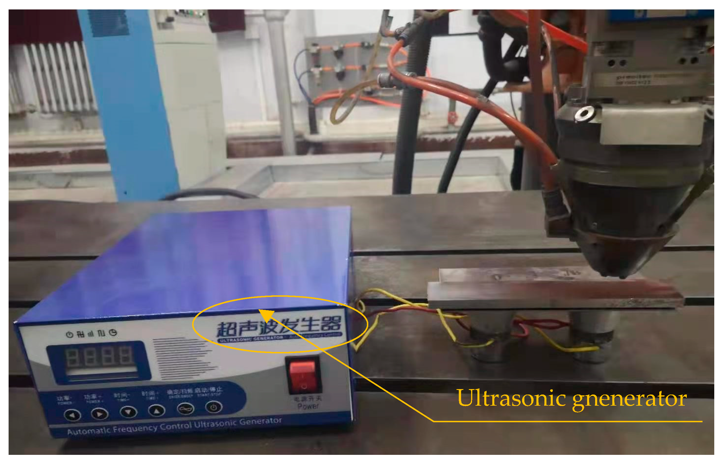
2.2. Experimental Methods

A fiber laser cladding processing system(YLR-3000, IPG Photonics Corporation, Oxford, MA, USA) is used in the experiment, with a six-axis linkage German KUKA industrial robot(KR30HA, KUKA Roboter GmbH, Augsburg, Germany) and a carrier gas powder feeder(FHPF-10, Feihong Laser S&T Co., Ltd., Beijing, China), and N2 is used as a carrier gas to transport the cladding powder to the surface of the substrate. During the cladding process, deionized water is used to cool the laser head and the entire laser processing system is controlled by a computer.
During the experiment, the laser power is set to 1.2 kW, the scanning speed is 3 mm/s, the powder feeding voltage is 10 V (9 g/min), the defocusing amount is 2 mm, the powder feeding air pressure (N2) 0.3 MPa, the powder carrier gas flow rate is 420 L/h, and the protection air pressure (N2) is 0.1 MPa. The laser wavelength is 1.07~1.08 μm. The power of the ultrasonic generator is 900 W, the frequency range is 20~42 kHz, and the ultrasonic frequencies are set to 0, 26 kHz, 30 kHz, 34 kHz and 38 kHz during laser cladding. In order to ensure the uniform transmission of ultrasonic vibration in the molten pool during the cladding process, the cladding starts after the ultrasonic generator is started 10 s, and the ultrasonic generator is turned off after the end of the cladding lag 10 s. The experimental equipment of ultrasonic laser cladding is shown in Figure 1. The ultrasonic vibrator and the substrate are connected by screws. After the experiment, the obtained cladding layer was analyzed and compared with the help of metallurgical microscope, scanning electron microscope (SEM, S-3400N, Hitachi, Tokyo, Japan), energy spectrum analyzer (EDS, EDAX Genesis 2000, EDAX Inc, Mahwah, NJ, USA), X-ray diffractometer (XRD, D/MAX-2500, Rigaku, Tokyo, Japan), microhardness tester (HVS-1000; Hui Ju Co., Ltd., Ningbo, China), and friction wear tester (MM-W1B, Jinan Time Shijin Testing Machine Co., Ltd., Jinan, China).

3. Experiment Results and Analysis

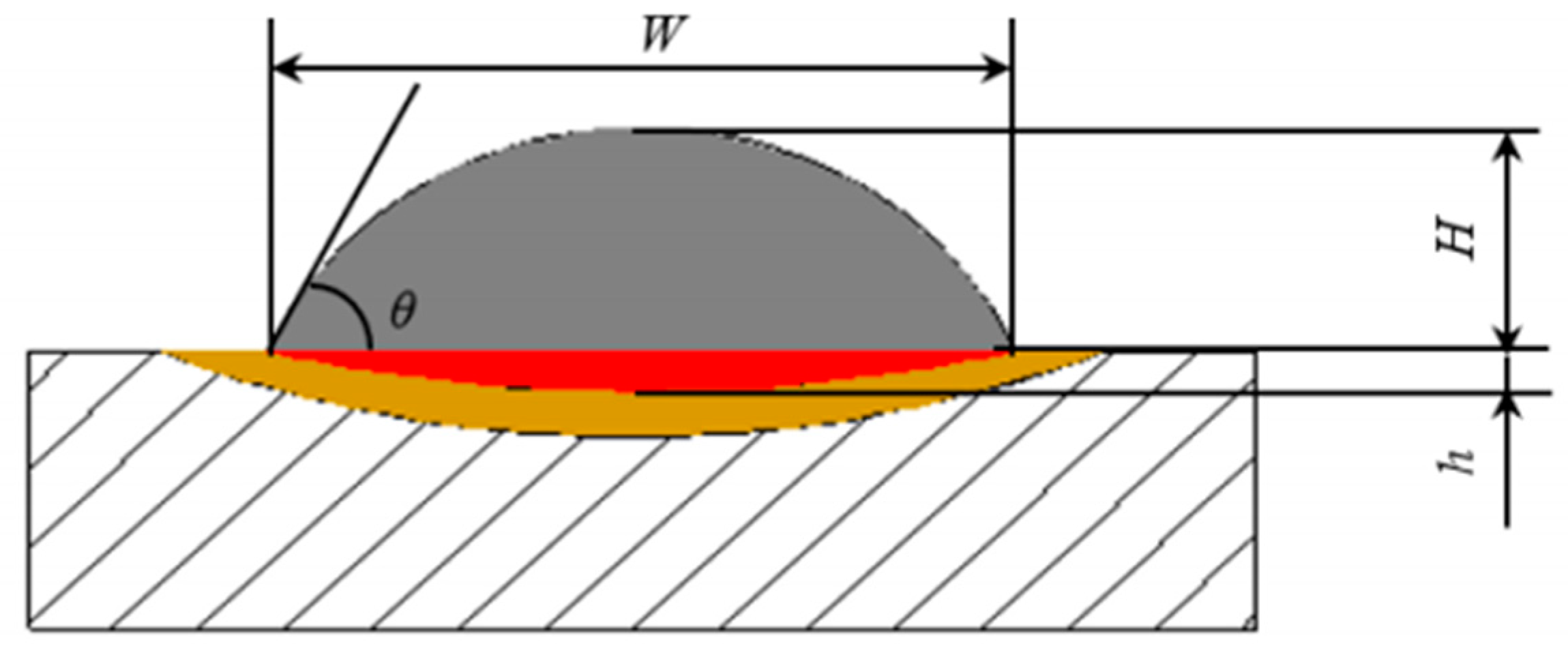
3.1. Morphology Analysis of the Cladding Layer

During laser cladding, the cladding layer macroscopic morphology determines the height and width of the cladding layer and the surface flatness of the multiple laps, which in turn affects the dimensional accuracy and forming quality of the metal specimen. Figure 2 is a schematic diagram of the single-pass laser cladding geometry. In the figure, W is the width of the cladding layer, H is the height of the cladding layer, h is the depth, the wetting angle of the single-pass cladding layer is θ, and η is the dilution rate.
If the dilution rate is too large, it will reduce the original characteristic properties of the base material, whereas if it is too small, it will cause poor bonding between the cladding layer and the base and increase the tendency of cracking. Therefore, under the premise of ensuring a good metallurgical bond between the coating and the substrate, a small dilution rate should be properly controlled.
The wetting angle θ can be calculated by Equation (1):
θ = 2 arctan ( 2 H W )
In the formula, H is the height of the cladding layer, mm; W is the width of the cladding layer, mm.
The dilution rate η can be calculated by Equation (2):
η = h H + h
Figure 3 shows the cross-sectional morphology of the cladding layer under different ultrasonic frequencies. The corresponding morphology parameters such as the width, height, dilution rate and wetting angle of the cladding layer are shown in Table 2. It can be seen from the table that when the ultrasonic frequency is less than 34 kHz, the width of the cladding layer increases from 3.93 mm without ultrasonic vibration to 4.36 mm, and the upper and lower edges begin to expand outward. When the ultrasonic frequency continues to increase to 38 kHz, the width of the cladding layer reduces to 4.03 mm. The height of the cladding layer decreases with the increase of ultrasonic frequency, from 0.98 mm without ultrasonic vibration to 0.69 mm, and it starts to rise again when the ultrasonic frequency increases to 38 kHz. The dilution rate of the cladding layer gradually decreases with the increase of the ultrasonic frequency. When the ultrasonic frequency is 34 kHz, there is a minimum of 20.05%, and when the ultrasonic frequency is 38 kHz, there is an increasing trend. As the height H and width W change, the wetting angle θ also changes. After ultrasonic vibration is applied, θ decreases significantly, and gradually decreases with the increase of the ultrasonic frequency. The minimum value is 34.08°. With the continuing increase of ultrasonic frequency, the wetting angle θ has an upward trend but it is not obvious.
Generally speaking, when the ultrasonic frequency is 34kHz, the topography parameters are the best, but when the ultrasonic frequency continues to increase, the topography parameters begin to develop in the direction that is not conducive to the quality of the forming. There is no obvious powder sticking phenomenon on the surface, the height of the cladding layer is small, the width is large, and the dilution rate is small (20%–40%). The reason for this is that a too large ultrasonic frequency will cause the matrix and the molten pool vibrates violently together, and the melt in the molten pool will shake or splash when disturbed, so that the surface of the cladding layer fluctuates greatly and the forming quality is poor.

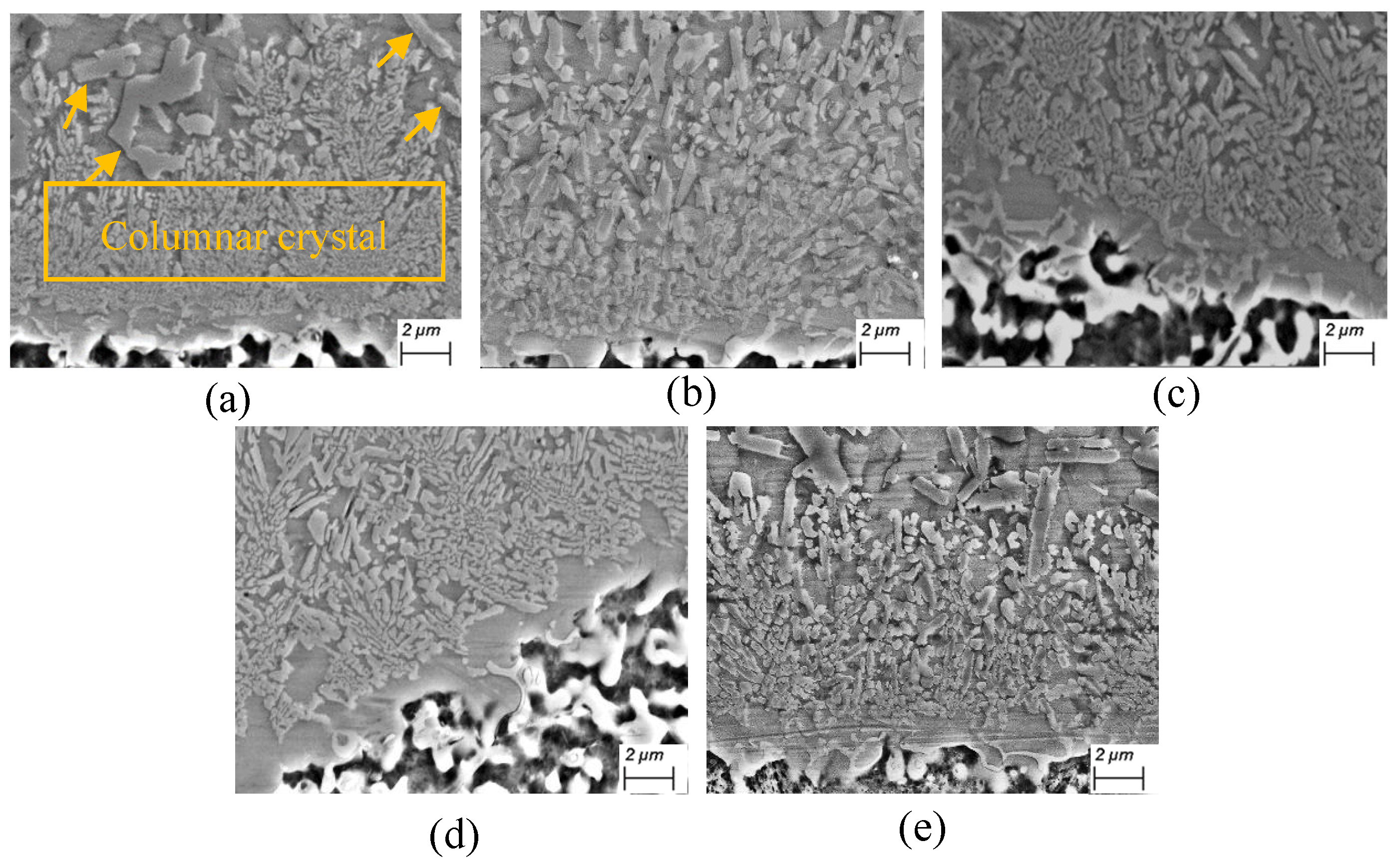
3.2. Microstructure Analysis of the Cladding Layer

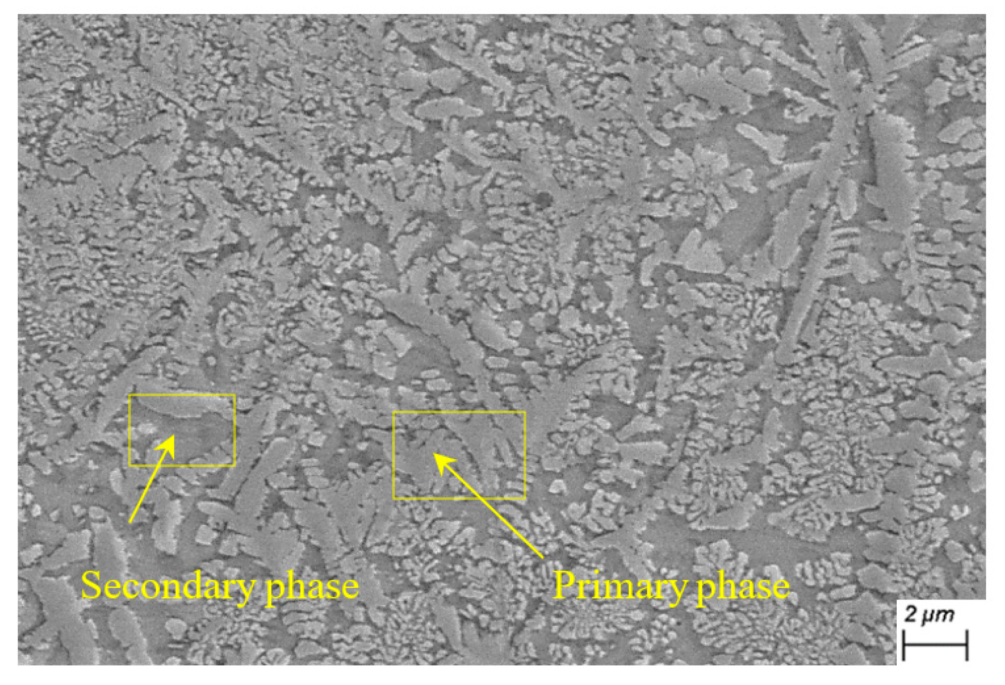
3.2.1. Microstructure of Cladding Layer

Figure 4 and Figure 5 show the cladding layer microstructures of the top and bottom at different ultrasonic frequencies.
When there is no ultrasonic vibration, in Figure 4a and Figure 5a, the cladding layer structure is coarse cell crystals, dendrites and columnar crystals, and there are more coarse secondary dendrites. That is because during laser cladding, as the crystallization process progresses, the changes from solid to liquid gradually advance to the middle of the molten pool, the temperature gradient of the molten pool gradually decreases, and the solidification cooling rate increases [10]. Too much melt enrichment at the crystallization front causes the composition to be too cold, which makes the interface unstable and cell crystals, dendrites and columnar crystals appear [7]. The crystallization process of the same microscopic area in the molten pool cannot be completed at the same time. First, coarse dendrites are formed, and the unsolidified liquid metal re-nucleates between the solidified dendrites to form a fine eutectic structure [7,11].
After ultrasonic vibration is applied, the structure becomes smaller rapidly, and with the increase of the ultrasonic frequency, the structure becomes smaller and smaller. When the ultrasonic frequency is 34 kHz, the top of the cladding layer does not even show obvious grain boundary crystal planes. This is because the cavitation bubbles deviate from the spherical shape under the alternating action of the positive and negative ultrasonic sound pressure; when the cavitation bubbles further collapse and pass through the molten metal, they will produce micro jets directed to the bottom of the molten pool and dendrites. The high-pressure shock produced by ultrasonic cavitation will break the interlaced crystalline network between dendrites and turn into many fine broken crystals. With the flow of the molten pool, these broken crystals are dispersed throughout the molten pool and become new nuclei to grow [12,13,14,15]. Meanwhile, when the ultrasonic frequency is 38kHz, the structure of the cladding layer begins to become coarse again.

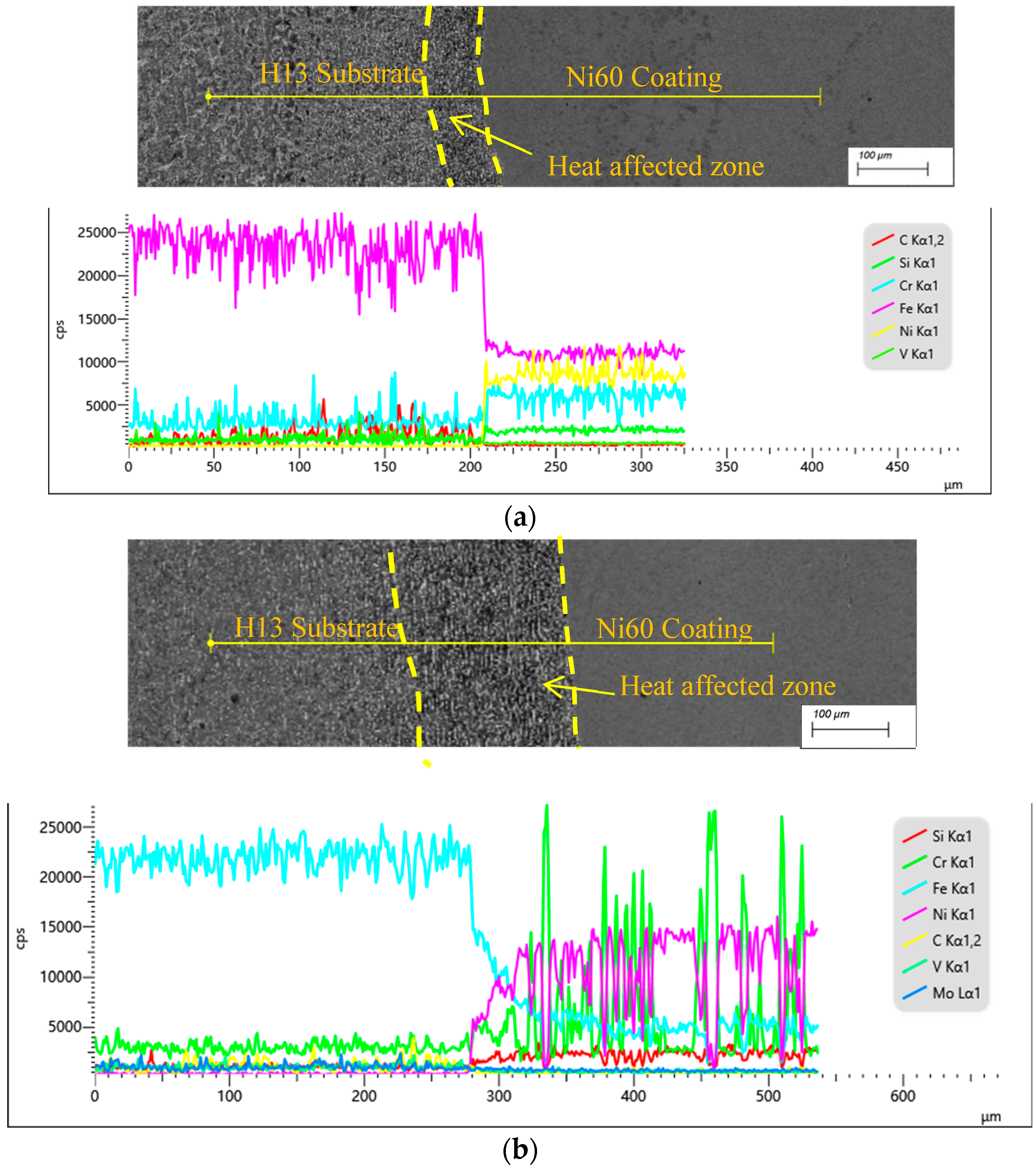
3.2.2. Segregation of Elements in the Cladding Layer

Figure 6 shows the line scan results of the cladding layer bonding interface when there is no ultrasonic vibration and the ultrasonic frequency is 34 kHz. The left side is the matrix, the middle is the bonding area (Heat Affected Zone, the area where the substrate structure changes significantly), and the right side is the cladding layer.
It can be seen from Figure 6a that when there is no ultrasonic vibration, the heat affected zone is small, and the content of each element at the interface between the matrix and the cladding layer changes gradually. Inhomogeneously, there is a large element segregation, and the content of Ni element fluctuates greatly in various positions.
In order to further analyze the effect of ultrasonic vibration on the elements distribution in the cladding layer, the elemental components of the primary and secondary phases in the cladding layer with synchronous 34 kHz ultrasonic vibration were scanned by EDS energy spectrum, and further microscopic composition of each phase was made, as is shown in Figure 7. Three points in the same area were taken for measurement and then the average of the measurement results was claculated. The scan results are shown in Table 3. It can be seen from the tables that the content of B, C, Cr and W in the main dendrite trunk of the primary phase (the first phase formed during nucleation) as hard phase elements in the microstructure of the ultrasonic vibration cladding layer is higher than that of the secondary phase(other phases precipitated subsequently during the growth process after the formation of the primary phase), and the area of the primary phase is large. The area of primary phase is greatly increased and distributed evenly.
The reason for the aforementioned is that after ultrasonic vibration is applied, nonlinear effects such as ultrasonic cavitation and acoustic flow can enhance the fluidity of the fluid in the molten pool. When the fluidity is strong, the molten matrix and cladding powder can be made better mixed to make the distribution of elements in the molten pool uniform, which will reduce the objective segregation caused by natural convection to a certain extent and reduce the interface effect, and the primary phase is generally a hard phase that precipitates first, and the area increase of the primary phase can significantly improve the mechanical properties of the coating. The content of Fe and Ni elements in the ultrasonic vibration cladding layer is also relatively large. Because the two atomic radii are close, they have the same crystal structure at high temperature and are prone to mutual diffusion to form a replacement solid solution, which makes the bonding strength between the coating and the substrate increase.

3.3. Microhardness of the Cladding Layer

Figure 8 shows the hardness distribution of the cladding layer at different ultrasonic frequencies. It can be seen from the figure that the hardness of the coating without ultrasonic vibration is the lowest, with an average microhardness value of 651.3 HV. The microhardness of the cladding layer with ultrasonic vibration applied at each measurement point is higher than that of the cladding layer without ultrasonic vibration, and there is a gradient drop from the top of the cladding layer to the substrate, indicating that a good metallurgical bond is formed between the two. The microhardness of the top cladding layer is the highest, gradually decreases in the heat-affected zone, and decreases to the minimum at the substrate. When 26 kHz ultrasonic vibration is applied, the average microhardness of the coating is 764.2 HV, which is 17.34% higher than the cladding layer without ultrasonic vibration; when the ultrasonic frequency is increased to 30 kHz, the average microhardness increases to 770.2 HV, which is 18.26% higher than the cladding layer without ultrasonic vibration. When the ultrasonic frequency is further increased to 34 kHz, the average microhardness is the largest 785.7 HV, which is 20.68% higher than that of the cladding layer without ultrasonic vibration. If the ultrasonic frequency is increased to 38 kHz, the average microhardness of the cladding layer is 876.9 HV, which is 34.64% higher than that of the cladding layer without ultrasonic vibration, althrough the hardness of each point fluctuates greatly.
Here are two reasons that cause the result: one is that although the microstructure uniformity of the cladding layer is improved, there are differences in the size of the structure in different tiny areas. The hardness value when the indenter of the durometer is in contact with the hard phase is larger and vice versa. The second is the microstructure, the hardness is also related to the element content in the micro-zone. The micro-zone with a higher content of reinforcing elements has a larger hardness and vice versa. From the perspective of hardness improvement and uniformity, the cladding layer with an ultrasonic frequency of 34 kHz is generally better, and the hardness values are evenly distributed without significant fluctuations.
In summary, the microhardness value of the cladding layer with ultrasonic vibration is significantly higher than that of the cladding layer without ultrasonic vibration. There are three main reasons. First, under the combined action of ultrasonic cavitation and acoustic current effects, the fluidity of the molten pool is enhanced, but the ultrasonic wave also disturbs the flow direction of the fluid in the molten pool. This means that the reinforcing elements rapidly and uniformly diffuse to the entire cladding layer, and the solid solution and dispersion strengthening of the reinforcing elements increase the average microhardness of the cladding layer. Second, the ultrasonic cavitation makes the cladding layer grains very fine, thereby increasing the average microhardness of the cladding layer. Third, the cavitation and acoustic flow effects of ultrasonic vibration significantly reduce the porosity in the molten pool, thereby increasing the microhardness [6,16,17]. Fourth, as can be shown by the Hall-Petch formula [18], the yield strength of the material increases as the grain diameter decreases, and the ultrasound refines the grains, which in turn increases the hardness of the coating.

3.4. Friction and Wear Properties of the Cladding Layer

3.4.1. Wear Rate of Cladding Layer

As shown in Figure 9, the wear amount of the non-ultrasonic vibration cladding layer and the 34 kHz ultrasonic vibration cladding layer under the same conditions was analyzed. After ultrasonic vibration is applied, the wear amount of the cladding layer is significantly reduced. When the time is 90 min, the wear amount of the ultrasonic vibration cladding layer is 34 mg, while which of the non-ultrasonic vibration cladding layer is 47 mg. The ultrasonic vibration cladding layer has good wear resistance.
The promotion of wear resistance is firstly due to the cavitation and acoustic effects of ultrasonic waves, which increase the fluidity of the molten pool. At the same time, when ultrasonic waves directly act on the surface of the molten pool, this disturbs the flow direction of the fluid in the melt and promotes a more uniform distribution of elements in the cladding layer. Secondly, defects such as pores and cracks in the ultrasonic vibration cladding layer are significantly reduced. Finally, under the cavitation effect of ultrasonic vibration, the grain structure changes from coarse dendrites to fine cells, and the grains are dense. The three reasons combined make the ultrasonic vibration coating have better wear resistance.

3.4.2. Friction and Wear Behavior of Cladding Layer

Figure 10 shows the wear morphology of the Ni60 coating under the conditions of no ultrasonic vibration and 34 kHz ultrasonic vibration; the sliding linear velocity of the wear test is 0.08325 m/s and the experimental load is 30 N. It can be seen from Figure 10a that when there is no ultrasonic vibration, the wear surface of the Ni60 cladding layer has a greater flaky peeling phenomenon, which is mainly manifested as brittle peeling. This is because the Ni-based coating is in contact with the friction pair. Plastic deformation occurs at the point. As the friction continues, the local temperature of the wear area increases, and the grinding pair and the matrix are locally welded due to high temperature. Then the welded area is torn due to relative movement and the tearing debris is repeated, it peels off from the coating surface during scratching, forming a typical adhesive wear morphology. At the same time, some of the wear debris generated adhesive accumulation due to the instantaneous high temperature during the friction process, and invading the surface of the substrate under the action of friction and load [18].
It can be seen from Figure 10b that the wear surface brittle spalling of the ultrasonic vibration cladding layer is significantly reduced, with only a small amount of small-area lump spalling, and a certain amount of shallow furrows appearing. The reason for this is that the 34 kHz ultrasonic vibration cladding layer has a fine structure, uniform distribution of hard phase elements and high hardness, so the plastic deformation of the matrix decreases during the wear process, the anti-adhesive and anti-cutting properties increase, and the flaking must be reduced. Additionally, due to the high hardness of the grinding pair, there is also a certain amount of abrasive wear at the friction contact point, so some small furrows appear.
In summary, ultrasonic vibration can significantly improve the wear resistance of the cladding layer. This is because the hardness of the cladding layer increases after the ultrasonic vibration refines the crystal grains. The improvement in wear resistance and hardness is ultimately due to the effect of ultrasonic vibration on the microstructure of the cladding layer. For the mechanical properties of metals at room temperature, the finer the crystal grains, the higher the mechanical properties. Secondly, the sound flow effect of ultrasonic vibration can significantly reduce defects such as pores and cracks in the coating, make the coating structure more uniform and dense, and can also improve its mechanical properties to a certain extent. In short, the improvement of the mechanical properties of the cladding layer is the result of the combined effect of the ultrasonic vibration’s fine-grain strengthening effect and the reduction of defects [19].

4. Conclusions

The Ni60 alloy cladding layer was prepared on the surface of H13 steel by two methods of non-ultrasonic vibration and auxiliary ultrasonic vibration. The inspection and analysis of the morphology, structure and properties of the coating showed that reasonable ultrasonic frequency can significantly refine the coating microstructure and improve the hardness and wear resistance, which is embodied in the following three aspects:
(1) When the ultrasonic frequency is increased from 26 kHz to 30 kHz, 34 kHz and 38 kHz, the dilution rate and wetting angle of the cladding layer gradually decrease. When the ultrasonic frequency is 34 kHz, the dilution rate and wetting angle have minimum values, respectively 20.05% and 34.08%.
(2) With the increase of the ultrasonic frequency, the microstructure of the cladding layer becomes smaller and smaller. It reaches the best state at the ultrasonic frequency of 34kHz, and the top of the cladding layer does not even see obvious grain boundary crystal planes. Meanwhile, when the ultrasonic frequency was increased to 38 kHz, the microstructure began to become coarse again.
(3) The fine crystal effect of ultrasonic vibration has significantly improved the microhardness and wear resistance of the cladding layer. When the ultrasonic frequency is 34 kHz, the average microhardness of the coating is 876.9 HV, which is 34.64% higher than that of the coating without ultrasonic vibration. When the wear time is 90 min, the wear amount of the coating with ultrasonic vibration is higher than that without ultrasonic vibration. The coating is reduced by about a third.

Author Contributions

Conceptualization, F.Y.; methodology, F.Y. and Z.M.; software, Z.M.; validation, L.F.; formal analysis, F.Y. and L.F.; investigation, Z.M.; resources, Z.M.; data curation, F.Y.; writing-original preparation, F.Y.; writing-review and editing, F.Y. and J.L.; visualization, J.L.; supervision, L.F.; project administration, J.L.; funding acquisition, J.L. All authors have read and agreed to the published version of the manuscript.

Funding

This research received no external funding.

Institutional Review Board Statement

Not applicable.

Informed Consent Statement

Not applicable.

Data Availability Statement

The raw/processed data required to reproduce these findings cannot be shared at this time as the data also forms part of an ongoing study.

Conflicts of Interest

The authors declare no conflict of interest.

References

  1. Wang, Y.; Zhao, S.; Gao, W.; Zhou, C.; Liu, F.; Lin, X. Microstructure and properties of laser cladding FeCrBSi composite powder coatings with higher Cr content. J. Mater. Process. Technol. 2014, 214, 899–905. [Google Scholar] [CrossRef]
  2. Williamson, E.H.; Gee, M.; Robertson, D.; Watts, J.F.; Whiting, M.J.; Yeomans, J.A. A comparative study of the wear performance of hard coatings for nuclear applications. Wear 2022, 488–489, 204124. [Google Scholar] [CrossRef]
  3. Ramirez, A.; Qian, M.; Davis, B.; Wilks, T.; StJohn, D.H. Potency of high-intensity ultrasonic treatment for grain refinement of magnesium alloys. Scr. Mater. 2008, 59, 19–22. [Google Scholar] [CrossRef]
  4. Ma, G.; Yan, S.; Wu, D.; Miao, Q.; Liu, M.; Niu, F. Microstructure evolution and mechanical properties of ultrasonic assisted laser clad yttria stabilized zirconia coating. Ceram. Int. 2017, 43, 9622–9629. [Google Scholar] [CrossRef]
  5. Wang, Y.; Liu, S.; Zhang, X.; Liu, W.; Li, R. Experiments and Analysis of 3450Fe/CeO2 Coatings by Ultrasonic Vibration Assisted Laser Claddin. China Mech. Eng. 2018, 29, 2600–2605. [Google Scholar]
  6. Li, M.; Zhang, Q.; Han, B.; Song, L. Microstructure and property of Ni/WC/La2O3 coatings by ultrasonic vibration-assisted laser cladding treatment. Opt. Lasers Eng. 2020, 125, 10548. [Google Scholar] [CrossRef]
  7. Zhan, W. Research on Technology and Properties of Ni60 Coating by Ultrasound-Assisted Laser Cladding. Master’s Thesis, Xinjiang University, Ürümqi, China, 2020. [Google Scholar]
  8. Du, S. Study on the Effect of Mechanical Vibration on the Properties of Induction Cladding Ni60+WC Coatings. Ph.D. Thesis, Qingdao University of Technology, Qingdao, China, 2018. [Google Scholar]
  9. Gao, G.; Guo, Z.; Li, K. Ultrasonic vibration assisted Ni60WC25 powder laser cladding technology. Heat Treat. Met. 2019, 44, 172–175. [Google Scholar]
  10. Fengxiao, H. An Investigation on Microstructure and Properties of Ni-Based Alloy by Laser Cladding and Laser Cladding Forming; Jilin University: Changchun, China, 2011. [Google Scholar]
  11. Bartsch, H.J. Handbook of Mathematical Formulas; Academic Press: New York, NY, USA, 1974. [Google Scholar]
  12. Li, M.; Han, B.; Wang, Y.; Song, L.; Guo, L. Investigation on lasercladding high-hardness nano-ceramic coating assisted by ultrasonic vibration processing. Opt. Int. Light Electron Opt. 2016, 304, 262. [Google Scholar]
  13. Shen, J.; Lin, C.; Yao, Y.; Xu, H.; Liu, J. Effect of Ultrasound Vibration on Microstructure and Propertise of Laser Cladding. Surf. Technol. 2019, 48, 226–232. [Google Scholar]
  14. Fan, Z.; Wang, K.; Dong, X.; Duan, W.; Wang, R.; Mei, X.; Wang, W.; Cui, J.; Zhang, S.; Xu, C. Evaluation of microstructural evolution and corrosion types in ultrasonic assisted laser re-melted thermal barrier coatings underexposure to molten salts. Mater. Lett. 2017, 188, 145–148. [Google Scholar] [CrossRef]
  15. Liu, H.; Xu, Q.; Wang, C.; Zhang, X. Corrosion and wear behavior of Ni60CuMoW coatings fabricated by combination of laser cladding and mechanical vibration processing. J. Alloys Compd. 2015, 621, 357–363. [Google Scholar] [CrossRef]
  16. Liu, X.; Osawa, Y.; Takamori, S.; Mukai, T. Microstructure and mechanical properties of AZ91 alloy produced with ultrasonic vibration. Mater. Sci. Eng. A 2008, 487, 120–123. [Google Scholar] [CrossRef]
  17. Cui, Z.Q.; Qin, Y.C. Metallurgy and Heat Treatment, 2nd ed.; China Machine Press: Beijing, China, 2007. [Google Scholar]
  18. Shao, X. Prepariation and Properties of Ultrasonic Vibration Assisted Laser Clad Strengthened Coating on High-Speed Wheel/Rail Steel. Ph.D. Thesis, East China Jiaotong University, Nanchang, China, 2017. [Google Scholar]
  19. Wang, Y.; Li, C.; Jiang, F.; Zhang, J.; An, X. Effect of Ultrasonic Assistance on Mechanical Properties of Laser Cladding Al2O3-ZrO2 Ceramic Coating. Surf. Technol. 2020, 49, 309–319. [Google Scholar]
Figure 1. Experimental equipment for ultrasonic assisted laser cladding.
Coatings 12 01305 g001
Figure 2. Schematic diagram of laser cladding single-pass geometry.
Coatings 12 01305 g002
Figure 3. Cross-sectional morphology of the cladding layer at different ultrasonic frequencies.
Coatings 12 01305 g003
Figure 4. SEM pictures of the top layer (Ni60) under different ultrasonic frequencies. (a) 0; (b) 26 kHz; (c) 30 kHz; (d) 34 kHz; (e) 38 kHz.
Coatings 12 01305 g004
Figure 5. SEM pictures of bottom layer (Ni60) under different ultrasonic frequencies. (a) 0; (b) 26 kHz; (c) 30 kHz; (d) 34 kHz; (e) 38 kHz.
Coatings 12 01305 g005
Figure 6. Line scan result of cladding layer metallurgical bond zone. (a) No ultrasonic vibration; (b) 34kHz ultrasonic vibration.
Coatings 12 01305 g006
Figure 7. Primary phase and secondary phase EDS point scanning position of ultrasonic vibration Ni60 cladding layer.
Coatings 12 01305 g007
Figure 8. Effect of ultrasonic vibration on cladding layer microhardness.
Coatings 12 01305 g008
Figure 9. Wear of the cladding layer with or without ultrasonic vibration.
Coatings 12 01305 g009
Figure 10. Wear morphology of the cladding layer with or without ultrasonic vibration. (a) No ultrasonic vibration; (b) 34 kHz ultrasonic vibration.
Coatings 12 01305 g010
Table 1. Chemical composition of substrate and coating (mass%).
ElmentsCSiMnCrMoVPSFeBW Ni
H130.380.920.2851.20.950.020.03Bal.------
Ni600.654.0--15--------153.53Bal.
Table 2. The width, height, dilution rate and wetting angle of the cladding layer with different ultrasonic frequencies.
f/kHzW/mmH/mmh/mmDilution Rate η (%)Wetting Angle θ (°)
03.930.980.4531.4650.25
264.050.840.2422.1244.92
304.210.760.2121.8343.50
344.360.690.1820.0534.08
384.030.710.2021.1736.12
Table 3. Types, mass percentages and atomic ratios of elements in the crystal boundary area.
AreaElementBCSiCrFeNiW
Primary phasewt%10.1710.252.3316.0912.7447.381.04
at%29.1426.452.579.597.0725.010.18
Secondary phasewt%8.616.863.659.9115.2555.71--
at%27.3719.634.476.559.3832.60--
Publisher’s Note: MDPI stays neutral with regard to jurisdictional claims in published maps and institutional affiliations.

