Article

Evaluation of the Long-Term Performance of Marine and Offshore Coatings System Exposed on a Traditional Stationary Site and an Operating Ship and Its Correlation to Accelerated Test

by
Krystel Pélissier
1,*,
Nathalie Le Bozec
1,
Dominique Thierry
1,2 and
Nicolas Larché
1
1
French Corrosion Institute, Part of RISE, 220 Rue Rivoalon, 29 200 Brest, France
2
RISE Research Institutes of Sweden, Isafjordsgatan 28A, 164 40 KISTA, Sweden
*
Author to whom correspondence should be addressed.
Coatings 2022, 12(11), 1758; https://doi.org/10.3390/coatings12111758
Submission received: 29 October 2022 / Revised: 9 November 2022 / Accepted: 12 November 2022 / Published: 16 November 2022

Abstract

:
Anticorrosive coatings are widely used to protect steel against corrosion. Different standards exist to access the corrosion performance of anticorrosive paints. Among them, the so-called neutral salt spray test (NSST-ISO 9227) or cycling corrosion tests ISO 12944-6, ISO 12944-9, NACE TM0304, or NACE TM0404 can be named. It is well-known that some accelerated corrosion tests are not fully representative of the field exposure results. However, a lack in the literature exists correlating accelerated tests to field exposure, especially when long-term durations are considered. In this study, 11 different organic coatings have been investigated in terms of coating resistance to corrosion creep in two types of field exposure sites, namely a stationary site and an operating ship, and their performance was compared to two accelerated tests (ISO 12944-9 and modified ASTM D5894 standard). The results showed differences in the sites’ corrosivity and the coating systems’ performance as a function of the exposure sites. A lack of correlation exists between the ISO 12944-9 standard and the stationary site, due to the latter’s high corrosivity, while, to the contrary, a satisfying correlation with the operating ship was demonstrated; whereas, the modified ASTM D5894 standard showed a satisfying correlation with both types of sites.

1. Introduction

The corrosion of metals is still and will always be a problem when designing any structures that will sustain the effects of the environment. NACE international conducted a global study on corrosion costs and on preventive strategies in 2013 [1]. This showed that the estimated global cost of corrosion was approximatively 3.4% of the global gross domestic product of developed countries. Several ways exist to protect metals against corrosion; one of the most popular is the use of anticorrosive coatings, as they are a cost-effective solution. The principal aim of an anticorrosive coating is to delay corrosion by being a barrier to ions, oxygen, or water, more or less actively, depending on the type of coating chosen [2]. Over the years, coating technology has been constantly evolving, and new technologies such as coating with low volatile compounds (VOCs), new zinc primer technology, or smart coatings, for example, keep emerging [3,4]. Thus, the choice of an adequate anticorrosive coating for a given application is crucial, as it will determine the cost of the initial structure and the maintenance costs throughout its life.
Typically, an anticorrosive coating is a multilayer system with at least one primer; the first layer to be applied is in contact with the metallic surface, and a topcoat gives the aesthetic properties of the system. The primer has an essential role, as it must have good adhesion property, give corrosion protection, and have good adhesion with the following layer. Three types of protection mechanisms delivered by the primer exist, namely the barrier, sacrificial protection, and inhibitive/passive protection [4,5]. Barrier protection allows for a reduction in the transport of corrosive elements such as water, ions, or oxygen to the metallic coating, whereas sacrificial and inhibitive protection rely on the action of pigments to offer protection. Sacrificial protection is based on the galvanic effect, where a pigment, traditionally zinc, will be more electrochemically active than the metallic surface and, thus, preferentially reactive with corrosive species, leading to its dissolution. In the case of inhibitive protection, the surface will be passivated by the dissolution of a soluble pigment when in contact with moisture.
They are two typical ways to select an appropriate anticorrosive coating: by performing field testing or by performing accelerated corrosion testing in a laboratory. An ideal accelerated test is designed to reproduce the degradation obtained during field exposures and to accelerate it correctly and homogeneously, for whatever material is being considered. Up until now, one of the most common accelerated tests used is the continuous salt spray test (ISO 9227). This test has been used for all kinds of application or material testing including anticorrosive coatings [6,7,8,9,10]. Until 2018, it was the recommended test for anticorrosive coatings up to C5 class in the ISO 12944-6:1998 standard [11]. However, in the last version of ISO 12944-6:2018, the cyclic test that was used only for offshore coatings was integrated as an appropriate test regime for certain corrosivity classes defined by the ISO 12944-2 standard [12]. This change of policy towards neutral salt spray test originated from the heavy criticism of the scientific community towards it and towards its reliability in predicting performance of coatings exposed in outdoor field exposures [13,14,15]. This is the reason why cyclic conditions (with no constant pollution, constant temperature, or constant relative humidity) are beginning to be preferred, even though several days of salt spray phases can still be present as a function of the test [16]. It should be mentioned that accelerated corrosion tests using cycling conditions show, in general, a greater correlation with field exposures [14,17,18,19]. Concerning the correlation of ISO 12944-9 with field exposures, the literature is conflicting, as no systematic correlation with field exposures can be found. This can be explained by a large variation in the results from laboratory to laboratory. Indeed, Le Bozec et al. [20], in a round robin investigation, obtained repeatability and reproducibility intervals between laboratories of about 34% and 113%, respectively. In addition, the correlation to field exposures seems to be dependent on the presence of coatings with poor performance in the text matrix. It should also be noted that this kind of testing cannot reproduce cosmetic defects such as blistering or rusting, as they are based mostly on the degradation from the scribe line.
The major concern in field exposures is not necessarily its lack of representativity towards service conditions, even though traditional sites might not be totally representative, but rather its time consuming and costly nature as, generally, many years of field exposures are needed to properly characterize coating performance. One can, thus, understand that it is not the best solution, especially regarding coating development.
Thus, it is better to connect the two approaches, as accelerating testing will allow for a quick identification of the coatings with poorer performance and can be used for coating development, whereas field exposures will give information about the global performance of the coating (including all modes of degradation and environmental stresses) and not on a particular coating property, e.g., corrosion from the scribe line, such as in the case of accelerated tests.
This study focused on evaluating the long-term performance of 11 coating systems, mostly differing by their primer action (barrier or sacrificial), in two types of field exposure sites, namely an inshore/stationary site and an offshore site (operating ship),and comparing it to their performances in two accelerated tests (ISO 12944-9 and modified ASTM D5894 standard). The results showed differences in the sites’ corrosivity and the performance of the coating systems as a function of the exposure sites (inshore vs. offshore). A lack of correlation was found between the ISO 12944-9 standard and the stationary site, while, on the contrary, a satisfying correlation with the operating ship was demonstrated, whereas the ASTM D5894 standard showed a satisfying correlation for both types of sites.

2. Materials and Methods

2.1. Painted Samples

All samples were manufactured from raw steel DH36 of dimensions 100 mm × 175 mm, for which the composition is given in Table 1.
They have been blasted to obtain a grade level of Sa21/2 and a surface profile MG according to ISO 8503-1 [21]. The selection of the different paint systems given in Table 2 was made to cover two of the main mechanisms of protection (barrier and sacrificial) and a large range of performance based on supplier experience and past studies [14,22]. Two samples per system were tested.
In addition to the paint systems, reference panels of carbon steel (DC0.1) and zinc (99.5%) of size 150 mm × 100 mm were exposed for one year to calibrate the field sites according to ISO 12944-2 standard [12]. The metal loss was calculated after removal of corrosion products by pickling according to ISO 8407 standard [23]. The corrosion products for steel and zinc were removed by chemical pickling in Clark’s solution (1L HCl ρ = 1.19 g.mL−1, 20 g Sb2O3, 50 g SnCl2) and glycine (250 g C2H5NO2 in 1L of demineralized water), respectively. Triplicates were used for the reference panels.

2.2. Description of the Field Sites

In this study, two types of field sites were considered: a stationary site (static) and a real structure (an operating ship). Previous studies have demonstrated that the exposure conditions and, thus, the corrosivity of real structures were more aggressive than stationary sites. It showed the importance to take into account both type of sites when studying painted systems’ performance in field exposures [22,24].
Stationary sites are classical inshore sites where corrosion studies are typically conducted. In this investigation, a marine site was selected, namely Brest site, located on the French coast. The painted systems were exposed at 45° facing south. The distance to the sea was less than 5 m.
The exposure on the real structure was realized on an operating ship (Enez Sun) doing a daily routine (July–August: 6 h/day—rest of the year: 2–4 h/day) between Audierne and Sein Island in Brittany (France). The distance between Audierne and Sein Island was 23 km. The coated materials were exposed on an area with no disturbance from passengers and where they could be exposed correctly to the climatic conditions, as illustrated in Figure 1.
The climatic conditions for Brest site are reported in Table 3. The operating ship was not instrumentalized; thus, there is no data on the climatic conditions for this specific site. However, data are available from a similar study involving a ship from the same company [22]. The only difference between the two studies was on the rotation done by boat, for Audierne—Sein Island and Brest—Ouessant Island, respectively. In this similar study, it was shown that the climatic conditions (temperature and relative humidity) were nearly the same between the operating ship and the stationary site (Brest site in both studies). It can then be assumed that in this present study, the climatic condition between the Enez Sun and Brest site will be close. On the other hand, the same reasoning cannot be accomplished for the chloride deposition, as the localization for the two operating ships was not similar. It can only be assumed that the chloride deposition will be higher for the operating ship in comparison to the stationary site.

2.3. Description of the Accelerated Tests

In addition to field exposures, other sets of samples were tested according to two accelerated tests, namely the ISO 12944-9 and ASTM D5894 standards [16,25]. As shown in Table 4, the cyclic corrosion test in the ISO 12944-9 standard consisted of weekly cycles of 3 days UV/condensation followed by 3 days of neutral salt spray test and 1 day at −20 °C. It can be noted that this test requires handling the samples 3 times a week. The test duration was 4200 h (approximately 6 months). The tests were carried in a QUV chamber (Q Panel), salt spray cabinet (Ascott S1000S), and climatic chamber (Secasi-SLT 100-40). Two replicates per system were tested.
A cyclic test according to ASTM D5894 standard was also carried out for a total duration of 3 months, as given in NACE TM0304 or NACE TM0404, for rust creepage resistance test (see Table 5) [26,27]. This cyclic corrosion test consisted of a week of UV/condensation and a week of alternating exposure to salt spray using synthetic seawater (1 h) and drying (1 h). The salt spray solution used for the salt spray phase was prepared according to ASTM D1141 [28] and not according to ASTM D5894 standard. This solution was selected to be more in line with aerosols encountered in field exposures. It can be noted that this test needed two pieces of equipment and handling of samples twice a week. The tests were carried in a QUV chamber (Q Panel) and salt spray cabinet (Excal BS17–Climats). Two replicates per system were tested.

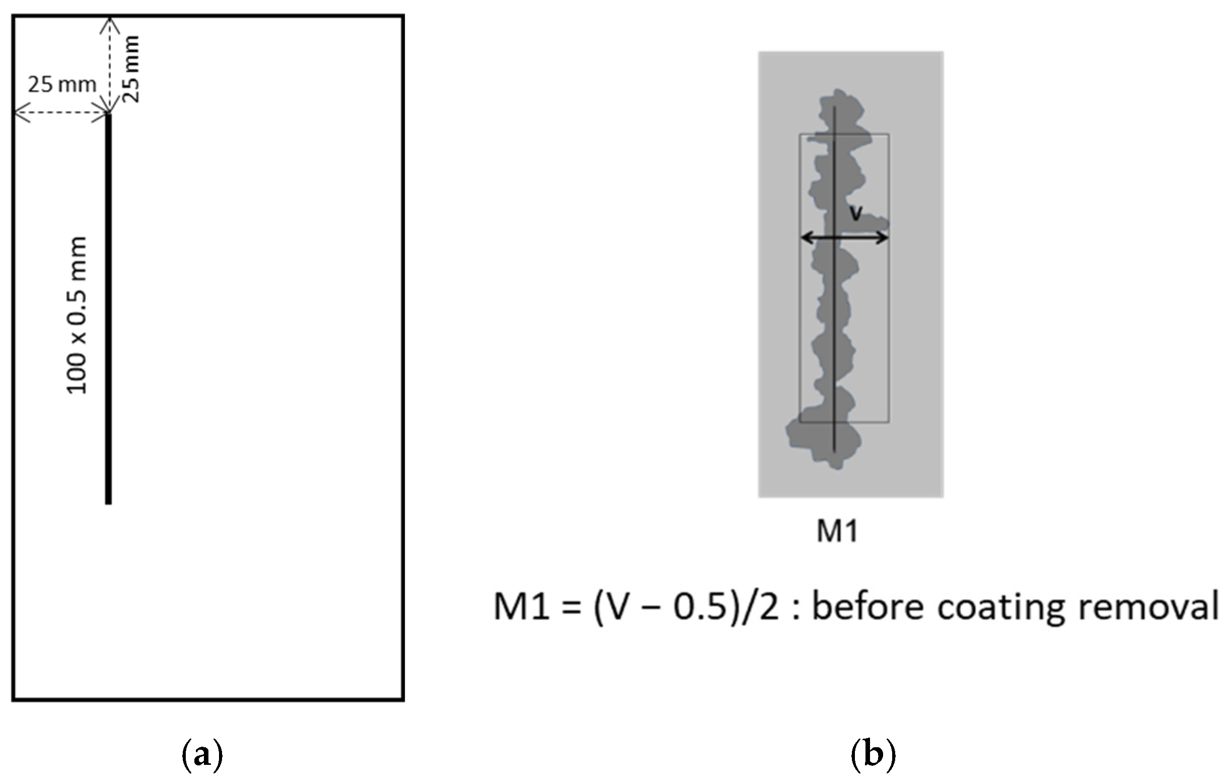
2.4. Sample Preparation and Evaluation

Prior to exposure, a vertical scribe parallel to the longest side of 100 mm × 0.5 mm was applied using an Elcometer 1538 scribing tool equipped with a rectangular blade (see Figure 2a). Edges and backsides were protected with tape. After exposure (either field or laboratory), the samples were evaluated according to ISO 4628-2/3/4/6 in terms of visual appearance (blistering, rusting, cracking, and chalking, respectively) [29,30,31,32]. Regarding the scribe creep, only the maximum value M1 was considered in this study, as the end of the period of exposure for the operating ship and the stationary site was not the same, i.e., 6 years and 10 years, respectively (see Figure 2b).

3. Results

3.1. Field Exposures

3.1.1. Corrosivity

Carbon steel and zinc coupons were exposed, in addition to the painted panels, to assess the corrosivity of the sites, and the results for the carbon steel and zinc are reported in Table 6. The data were obtained by mass loss, as defined in the experimental section. The corrosivity class according to ISO 12944-2 is also given [12].
As expected, the carbon steel mass loss for the stationary site (Brest) was inferior to that of the carbon steel mass loss of the operating ship (Enez Sun). The stationary site was classified as C5, whereas the studied location on the Enez Sun was classified as CX, for carbon steel. This important mass loss for the operating ship was in accordance with the literature data [22]. As the climatic data (temperature and relative humidity) were rather similar for the two sites, it can be supposed that the difference in the aggressiveness between the sites was mostly due to the action of the chloride deposition. In addition, due to its operating nature, it is not impossible that some splashing could have happened at the location on the ship. Nearly the same ratio of aggressiveness as the carbon steel was observed for the zinc mass loss, i.e., the ship was nearly twice as aggressive compared to the stationary site. This is in accordance with the high sensitivity of zinc towards chloride.

3.1.2. Site Comparison

As already mentioned above, the final time of exposure between the two sites was not the same. This was due to the difference in the site’s aggressiveness and the global degradation of the painted panels. Indeed, with the Enez Sun site being more aggressive, it was not possible to continue the exposition of the panels, in contrast to the stationary site, where the exposition was continued for up to 10 years. In any case, the data on the coating degradation for up to 6 years are still interesting, as they are close to the time of service (7 years) for a medium durability class, as defined by the ISO 12944-1 standard [33].
The maximum scribe creep, before coating removal after 6 years of exposure for the stationary site (Brest) and the operating ship (Enez Sun), is represented in Figure 3. Apart from S1 (Zn ethyl silicate), which exhibited some blistering at both sites, no visual degradation (blistering nor rusting) was observed, in accordance with previous observations in the literature [14,19,24,34].
From these results, it is clear that primers relaying on a galvanic mechanism of protection are performing better than barrier primers, which is in agreement with the literature data [18,24,34]. This better performance can be explained by the additional sacrificial protection given by zinc particles in the primer and the production of zinc corrosion products in the scribe, as described in Figure 4 [4,5]. For the zinc primers tested in this study, several technologies were selected: zinc silicate (S1), traditional zinc epoxy primers (S2, S3, and S5), and a waterborne zinc epoxy primer (S4). Among the five zinc primers, S2 (epoxy Zn) was the primer showing the least degradation, and S5 (epoxy Zn) was among the worst systems for both sites. S2 (epoxy Zn) was among the zinc-rich primers having the highest percentage of zinc dust and a high thickness (75 µm), which can explain its good performance. For S5 (epoxy Zn), it is difficult to explain its behaviour, as it exhibited 80% of the zinc dust in the primer. Some discrepancies between the sites were seen when looking at the different systems’ performance, such as, for instance, S3 (epoxy Zn), which was the system with the lowest degradation for the stationary site (Brest) and the one with the highest degradation for the operating ship (Enez Sun).
For the stationary site (Brest), no real difference between the performance of S1 (Zn ethyl silicate) and S2 (epoxy Zn) was observed, despite S1 (Zn ethyl silicate) being a zinc silicate primer. These types of primer are believed to show good performance and can perform better than traditional zinc epoxy primer [19,35,36,37,38]. However, for the operating ship, the zinc silicate system showed significant degradation that was inconsistent with its expected performance. Indeed, ethyl silicate is believed to favour the duration of cathodic protection [38]. Even after one year of exposure, red rust was observed in the scribe, showing the fast consumption of the zinc particles in the primer, whereas, for S3 (epoxy Zn), for example, the scribe remained intact without red rust products. In addition, this system was the only one showing some blistering coherent with a poorer behaviour. In a recent publication, Knudsen et al raised the issue of only considering scribe creep as the parameter defining coating lifetime, as they linked blistering appearance to a drop in the barrier proprieties demonstrated by electrochemical characterization [34]. However, after studying different tests’ parameters (type of environmental stresses, presence of scribe, etc.), Renaud et al. concluded that the presence of an artificial defect was needed to properly rank these types of systems [39]. Thus, an open discussion exists in the scientific community about the best way to assess the performance of marine coatings.
Concerning the barrier coatings, S8 (epoxy glass flakes) was the paint system with the highest degradation for both sites, with a maximum scribe between 20 and 25 mm, in accordance with the expected behaviour of this system from previous studies. The paint system S10 (polyamine epoxy) behaved rather really good for both sites, despite being recommended only for the C3 atmosphere. Barrier primers with the addition of aluminium (S6 and S11) in their formulation showed good performance, nearly at the same level as some zinc primers.
Again, for one system S7 (epoxy aluminium), an opposite performance was observed between the stationary site and the operating ship. The behaviour of this particular system was atypical, as nearly no degradation was observed for the stationary site, for up to 6 years, whereas high degradation was observed for the operating ship. Similar results were already observed for this system in another study [14]. Indeed, this corresponded to the paint system S10 in the study performed by Le Bozec et al. (S7 in the present study), and high degradation was observed on the operating ship, whereas no degradation was observed for the stationary site (also for the Brest site) after two years of exposure. These results suggested that underpaint corrosion propagation needed high site aggressiveness to get started or a longer time of exposure, in the case of a less aggressive site, as suggested by the results of the current study. It is interesting to note that even though S7 is an epoxy pigmented with aluminium, this system did not exhibit the same performance as the other barrier primers with the addition of aluminium (S6 and S11). This could come from the percentage of aluminium pigment in the formulation. Unfortunately, this information was not available.
In general, the operating ship exhibited a higher degradation for both type of primers, with an average maximum scribe of 4.9 mm (2.1 mm for the stationary site) for zinc primers and 11.3 mm (7.6 mm for the stationary site) for barrier primers. The kinetic of degradation was followed by measuring the extent of underfilm corrosion (before coating removal) by image analysis, using Jmicro Vision software. It should be noted that the results are to be taken with care, as the analysis was performed on photographs and, for some periods of exposure, especially for the ship, due to on-site evaluation, the quality of the photographs was not optimum. Thus, these results are only given as an indication.
The evolution of the total area of underfilm corrosion (sum of from all systems) in mm2, as a function of the time of exposure for the stationary site and the operating ship for the zinc primers and the barrier primers, is given in Figure 5.
As expected, whatever the type of protection offered by the primer, the degradation was higher for the ship. However, the kinetic of degradation, even though it was higher, was not exactly the same as a function of the site, especially for the zinc primers. For the stationary site, the degradation was low and slow to increase, which is consistent with the activation of zinc particles and a certain duration (or break point time) of the cathodic protection, before switching to barrier-like mechanisms, whereas for the operating ship the increase in the degradation was more abrupt, with a somewhat stabilization after 72 months of exposure [40] (see Figure 6).
This most likely demonstrated the differences in the mechanism of corrosion propagation underneath the coating. In addition to being system-dependent, the corrosion propagation for zinc-rich primers is also determined by the environmental stresses [37,38]. Even though the global performance of the primer will be the same as a function of the environmental stresses, the activation of the zinc particles, the propagation of the corrosion, and the continuous activation of the surrounding zinc particles far from the scribe will change, as shown by Nazarov et al. [37]. It should be noted that the kinetic of degradation was also analyzed system by system, and nearly the same evolution was observed for whatever system was considered.
When looking at the barrier primers, the same type of kinetic of degradation was found with an initially slow increase and then a constant increase for both sites, with the increase being more important for the operating ship, in accordance with a higher aggressiveness shown by the corrosivity measurement (Table 6). In the case of the barrier-type primer, in atmospheric conditions, the propagation of the coating delamination is believed to alternate between cathodic delamination and anodic undermining as a function of the thickness of the electrolyte, with the constant progression of the delamination front [41,42].
Another way to compare the performance of the painted systems at the two sites is to represent the data using a box plot. Box plots are a statistical tool allowing to gauge the sensitivity of each system to the environmental factors of the sites. It is the size of the box that allows for this evaluation. Indeed, the more the size of the box is important, the more the system is sensitive to the environmental factors within the exposure sites, as it represents the spreading of the results at both sites. So, if a similar extent of degradation is obtained at both sites, the upper and lower box limits will be close. The upper and lower box limits represent 75% and 25% of the values, respectively. The band in the box is the median value, and the square is the mean value. Each box was calculated considering the results from both sites. For instance, the box plot at 2 years for S1 is taking into account the maximum scribe creep value at the Brest and Enez Sun sites (in the same box). This was carried out after 2 years and 6 years for each system at both sites (see Figure 7).
It can be seen that the zinc-rich primers, at the beginning of the exposure, were not that sensitive to the environmental factors, whereas some of them, S1 (Zn Ethyl Silicate) and S3 (Epoxy Zn), became sensitive after 6 years of exposure. This sensitivity was already sensed in the previous results, where a totally opposing performance was seen between the sites, i.e., high degradation vs. nearly no degradation. This sensitivity seemed, however, to be system-dependent. Le Bozec et al. [19] also observed that zinc primers were sensitive to environmental factors, in particular when splashing was involved, as the frequent spraying of a seawater aerosol accelerated the degradation of zinc materials.
Concerning the barrier primer, it seemed rather unaffected by the environmental factors, except for S7 (epoxy aluminium) and S8 (epoxy glass flakes) (only after 2 years). This observation showed that even though the extent of degradation will be influenced by the steel site’s corrosivity, a good paint system will remain a good paint system at both sites. This assumption did not work for S7 (epoxy aluminium), as this particular paint system was the only one exhibiting an opposite performance, as a function of the site, as already explained earlier.
The morphology of the corrosion at the scribe line was also compared as a function of the site; however, no real differences were seen (see Figure 8). Indeed, for both sites, the failure at the scribe was generally associated with blisters full of corrosion products, the cracking of the coating, and the quantity of blisters and cracks, which mostly depended on the corrosivity of the site towards carbon steel. This morphology suggested an underpaint corrosion mechanism governed by anodic undermining, as the painted systems were constantly wet or dry, depending on the meteorological data. This is in accordance with the literature data [14,18,19]. It should be noted that some filiform corrosion was seen for S10 (polyamine epoxy).
Simple linear regression was applied to evaluate the linear relationship between the two sites. According to the previous results, it is not surprising that no good linear correlation could be found between the stationary site and the operating ship, as exemplified in Figure 9. When the paint system S7 (epoxy aluminium) was excluded from the calculation, the coefficient of correlation, R2, was improved to 0.8. However, the satisfying correlation obtained was only due to the contribution of paint system S8 (epoxy glass flakes), which was the most degraded system. It was also observed by Knudsen et al. that a better correlation was obtained for coating systems with a poor performance, when comparing various combinations of coating systems between field exposures (5 years) and several accelerated tests [17,34]. The Spearman’s rank correlation coefficient was also calculated, and no strong relationship was found between the two sites. The Spearman correlation allows for estimating the degree of relationship between two sets of data, as well as how each set of data will influence the other (negative or positive influence).

3.2. Correlation between Accelerated Tests and Field Exposures

In addition to field exposure, accelerated tests, namely ISO 12944-9 and ASTM D5894 standards, were performed. As for the field exposures, no cosmetic degradation was observed for whatever paint systems and accelerated tests were considered. The results showed a large difference between the paints systems, with S8 (epoxy glass flakes) still being the most damaged one, followed by S11 (epoxy aluminium), S7 (epoxy aluminium), and S10 (polyamine epoxy), while the systems involving zinc primers showed a better performance for both standards, as depicted on Figure 10. However, the degradation observed for zinc-rich primers was still higher than for field exposures, even for the operating ship. Knudsen et al. [34], in a recent study, observed that the ISO 12944-9 standard was not able to replicate the beneficial effect of zinc pigmentation in the primer due to a high average acceleration factor in comparison to the barrier primers, which were 16 and 2.3, respectively. In this study, the beneficial effect of zinc was properly replicated by both accelerated tests, even though the average acceleration factor for the zinc-rich primer was twice the one calculated for the barrier primers for both standards.
It appeared that the accelerated tests could give satisfactory results when predicting the extreme systems (the best and the worst). However, between these “extremes”, the accelerated tests were not necessarily able to correctly rank the painted systems when considering the stationary site (Brest), as shown by the linear regression analysis between the results from the accelerated tests and from the field exposures (see Figure 11). Indeed, for the stationary site, the beginning of a satisfying correlation with the ISO 12944-9 standard was only driven by S8 (epoxy glass flakes), so, when excluding this system, no correlation was obtained. On the contrary, for the operating ship, a correct correlation was obtained, which was improved by excluding S11 (epoxy aluminium) and was still standing without the contribution of S8 (epoxy glass flakes).
These results are in agreement with the literature, where an insufficient correlation between the ISO 12944-9 standard and field exposure is generally obtained due to too important degradation in the accelerated tests [14,17,43]. This observation can be strengthened by the results for the modified ASTM D5894 standard, where satisfactory results were obtained for both sites, even the stationary site when S8 (epoxy glass flakes) was excluded (with a satisfying correlation obtained after 7 years of exposure). In addition to having a lower test duration than the ISO 12944-9, this test is less aggressive [44]. This is also in accordance with the normative evolution of the ISO 12944 standards, which now include a lowered test duration, to be in line with C5 class corrosivity or lower corrosivity classes. The ISO 12944-9 standard with 4200 hours of testing is now specified for the CX exposure site.
Exposing paint systems in the outdoors remains the best way to evaluate the performance of paint systems at a given exposure time. As is well-known, this type of test can be time-consuming, so accelerated tests are often used. However, it can be difficult for accelerated tests to mimic all types of environments. Linear regression analysis remains the most simple and quick way for the comparison of results between field exposures and accelerated tests. Still, this analysis is frequently performed using a specific exposure duration, e.g., 2 years, which can lead to misinterpretation. Furthermore, as accelerated tests can, generally, induce too much degradation, it is not surprising that short period of exposure can lead to no correlation at all. That is why the variation of the coefficient of correlation for both sites, as a function of the time of exposure and the accelerated tests, was analyzed and is reported in Figure 12.
For each period of exposure (1 year, 2 years, etc.) and for both sites, the coefficient of correlation was optimized, and, frequently, one system had to be excluded to optimize the correlation. For the modified ASTM D5894 standard, S9 (polyamide epoxy glass flakes) was, most of the time, the excluded system. This exclusion was linked to the high degradation obtained in the modified ASTM D5894 standard, even when compared to the results from the ISO 12944-9 standard, which is considered to be more aggressive. For the stationary site, for a short period of exposure, the first being 3 years, one system was excluded, and, after 3 additional years, another one was excluded. This behaviour was linked to the build-up of sufficient degradation, when the time of exposure was increasing. Each exclusion is specified in the caption of Figure 12.
When looking at the evolution of the correlation between the ISO 12944-9 standard and both sites, no correlation was observed for the stationary site, whatever the time of exposure was, as the correlation was only driven by S8 (epoxy glass flakes). For the operating ship, it took 3 years to note a satisfactory correlation, which was rather stable as the time of exposure increased. It also took 3 years to observe an acceptable coefficient of correlation, when considering the modified ASTM D5894 standard and the operating ship. However, this seemed to start decreasing with an increase in the time of exposure. It can be supposed that with the time of exposure increasing, the aggressiveness of the accelerated test was not sufficient to cope with the aggressiveness of the site. This seemed to confirm that the ISO 12944-9 standard was better adapted to offshore sites. When taking into account S8 (epoxy glass flakes), it took 5 years to reach a correct coefficient of correlation for Brest. When excluding S8 (epoxy glass flakes), it took a longer time, i.e., 7 years (R2 = 0.8). As mentioned earlier, the samples were exposed for a longer time at the stationary site (10 years).

4. Discussion

As presumed, the aggressiveness of a real structure (an operating ship) when considering the performance of coating systems is truly superior to the aggressiveness of a stationary site. The results showed a higher degradation for both type of primers, which was in line with a previous study by Le Bozec et al. [24]. This could have been anticipated, as the conditions are harsher on an operating ship, originating from a possible splashing effect [22]. However, apart from the study cited earlier, no other study has been carried out, until now, on this type of structure. This can be explained by the difficulty of having access to this type of exposure site.
From the results, it was also evident that the aggressiveness of the site was not necessarily a major factor when considering the zinc primers. Indeed, it was shown, by using a statistical representation of the data, that the sensitivity of zinc-rich primers to environmental factors was system-dependent. This is not surprising, as the effectiveness (extent and duration) of a zinc-rich primer to protect the surface is linked to several parameters such as the coating nature, the content of the zinc dust, and the morphology of the zinc dust. Furthermore, the protection offered by zinc-rich primers is partly due to the build-up of corrosion products, and their nature (composition and structure) depends on the conditions that the coating system is exposed to [45]. The protection of barrier primers, however, depends mostly on the thickness of the coating, its generic type, and the nature of the binder [5].
A correlation between the field exposures and accelerated tests was found when considering the operating ship and the ISO 12944-9 standard, whereas no correlation was observed for the stationary site. The literature is contradictory on the possible correlation of the ISO 12944-9 standard with stationary sites [17,18,34]. An explanation could come from the high variation of the results obtained with the ISO 12944-9 standard, as shown by a round-robin investigation [20]. However, for the stationary site, this correlation also seemed to be dependent of the type of coating tested. Indeed, Knudsen et al. [34] made the assumption that the correlation was improved for coating systems with poor performance. This can be in line with the results of this study, when the correlation is enhanced once the poorest coating system is included. On the contrary, a satisfying correlation was obtained with ASTM D5894, which is half as aggressive than the ISO 12944-9 standard. However, without the contribution of the poorest system, 7 years of exposure were needed to acquire a sufficient correlation. For the operating ship, 3 years were needed for both standards, and it was shown that the correlation began to drop with the ASTM D5894 standard, due to too much degradation at the field site. These conclusions highlight that, as traditionally 2 years of exposure are performed when comparing accelerated tests and field exposure results, it is not surprising that most of the time no sufficient linear correlation is evidenced in the literature. This observation, thus, calls into question the previous conclusions about the correlation between accelerated tests and field exposures, when only 2 years of exposure are performed, and shows the importance of considering longer exposure durations. On the other hand, as shown, if the standard is really not adapted to reproduce the degradation observed in field, the correlation will be bad for whatever the time of exposure is for the stationary site, as the coefficient of correlation never increased, even after 10 years of exposure (R2 = 0.3). The aggressiveness of the test is, thus, a key point to take into account when selecting an accelerated test, as was also demonstrated by Le Bozec et al. [14] and Knudsen et al. [17].
Another point to mention is that, here, in contrary to what was supposed by Knudsen et al. [34] (based on another study and their results), field exposure of 2 years is not necessarily able to predict performance after 8 to 10 years, at least for the stationary site. Indeed, when trying to correlate the results after 2 years of exposure to the results after 6, 8, or 10 years of exposure, no correlation was found (R2 < 0.5) for whatever the exposure duration is, even when the barrier and zinc primers were examined separately. This was surely linked to the kinetic of degradation, which was not linear for both type of primers (see Figure 6). In addition, at least for zinc primers, a certain activation time is needed for the coating delamination to happen, which could explain this observation. Furthermore, the accumulation of corrosion products in the scribe and around the zinc particles in the coating can also create a barrier effect, which then slows down the degradation [5,45]. For the zinc primers, the same conclusion was drawn for the operating ship, when trying to correlate 2 years and 6 years of exposure. However, a significant correlation was found for the barrier primers (R2 = 0.84), while the kinetic of degradation had the same evolution as that of the stationary site. It is interesting to note that Knudsen et al. [34] used this assumption to point out the interest of using corrosion creep as the major indicator of coating performance in accelerated tests (ISO 12944-6 and/or 12944-9). Indeed, they pointed out, rightly, that the barrier properties of the coating were also to be considered, as they governed failure by blistering and rust penetration [46,47].

5. Conclusions

In this study, 11 coating systems were selected as a function of their mechanisms of protection, either sacrificial or barrier types, representing a large variety of technologies. They were exposed in two types of sites, i.e., a stationary site and a real structure. In addition, they were tested by accelerated tests, namely the ISO 12944-9 standard and modified ASTM D5894 standard. From the results obtained, the following conclusions may be drawn:
The operating ship was more aggressive than the stationary site when considering carbon steel mass loss (CX vs. C5), whereas the corrosivity class for zinc was the same for the two sites, with the operating ship showing more corrosion. Coating systems exposed on the operating ship were more degraded than for those on the stationary site. This observation was especially true for coating systems based on the barrier-protection mechanism.
The zinc primers exhibited a better performance for whatever site was considered. It was shown that zinc primers were more sensitive to environmental factors and that this was system-dependent, at least when considering scribe creep corrosion. Coating systems based on barrier primers exhibited more degradation, and their extent of degradation followed the corrosivity class of the sites (for carbon steel).
No correlation was observed between the ISO 12944-9 standard and the stationary site, whereas a satisfying correlation was obtained for the real structure. A rather correct correlation between the modified ASTM D5894 standard, which was seen for both types of sites. When looking at the evolution of the correlation over the years of exposure, it was noticed that at least 3 years of exposure were needed for the operating ship to acquire an acceptable correlation with the ISO 12944-9 standard or modified ASTM D5894 standard, whereas at least 5 to 7 years were needed for the stationary site and modified ASTM D5894.

Author Contributions

Conceptualization, K.P.; methodology, K.P.; validation, D.T.; formal analysis, K.P.; investigation, K.P.; writing—original draft preparation, K.P.; writing—review and editing, K.P. and D.T.; visualization, K.P.; supervision, N.L.; project administration, K.P. and N.L.B. All authors have read and agreed to the published version of the manuscript.

Funding

This research received no external funding.

Institutional Review Board Statement

Not applicable.

Informed Consent Statement

Not applicable.

Data Availability Statement

Not applicable.

Acknowledgments

We gratefully acknowledge the help of the members of the Member Research Consortium “Paints and Lining for steel and related alloys structures in atmosphere and immersion” and the valuable discussions during meetings.

Conflicts of Interest

The authors declare no conflict of interest.

References

  1. Koch, G.; Varney, J.; Thompson, N.; Moghissi, O.; Gould, M.; Payer, J. International Measures of Prevention, Application, and Economics of Corrosion Technologies Study. NACE Int. 2016, 216, 2–3. [Google Scholar]
  2. Bierwagen, G.P. Reflections on Corrosion Control by Organic Coatings. Prog. Org. Coat. 1996, 28, 43–48. [Google Scholar] [CrossRef]
  3. Morales, R.; Hempel, P.; Prieto, A.; Hempel, J.L. Challenging the Performance Myth of Inorganic Zinc Rich vs Organic Zinc Rich Primers and Activated Zinc Primers. In Proceedings of the NACE International’s Corrosion Conference, New Orleans, LA, USA, 26–30 March 2017; p. 9127. [Google Scholar]
  4. Pélissier, K.; Thierry, D. Powder and High-Solid Coatings as Anticorrosive Solutions for Marine and Offshore Applications? A Review. Coatings 2020, 10, 916. [Google Scholar] [CrossRef]
  5. Sørensen, P.A.; Kiil, S.; Dam-Johansen, K.; Weinell, C.E. Anticorrosive Coatings: A Review. J. Coat. Technol. Res. 2009, 6, 135–176. [Google Scholar] [CrossRef]
  6. Kunce, I.; Królikowska, A.; Komorowski, L. Accelerated Corrosion Tests in Quality Labels for Powder Coatings on Galvanized Steel—Comparison of Requirements and Experimental Evaluation. Materials 2021, 14, 6547. [Google Scholar] [CrossRef]
  7. Stojanović, I.; Šimunović, V.; Alar, V.; Kapor, F. Experimental Evaluation of Polyester and Epoxy-Polyester Powder Coatings in Aggressive Media. Coatings 2018, 8, 98. [Google Scholar] [CrossRef] [Green Version]
  8. López-Ortega, A.; Areitioaurtena, O.; Alves, S.A.; Goitandia, A.M.; Elexpe, I.; Arana, J.L.; Bayón, R. Development of a Superhydrophobic and Bactericide Organic Topcoat to Be Applied on Thermally Sprayed Aluminum Coatings in Offshore Submerged Components. Prog. Org. Coat. 2019, 137, 5376. [Google Scholar] [CrossRef]
  9. Almeida, E.; Santos, D.; Uruchurtu, J. Corrosion Performance of Waterborne Coatings for Structural Steel. Prog. Org. Coat. 1999, 37, 131–140. [Google Scholar] [CrossRef]
  10. López-Ortega, A.; Bayón, R.; Arana, J.L. Evaluation of Protective Coatings for High-Corrosivity Category Atmospheres in Offshore Applications. Materials 2019, 12, 1325. [Google Scholar] [CrossRef] [Green Version]
  11. ISO 12944-6; Paints and Varnishes—Corrosion Protection of Steel Structures by Protective Paint Systems—Part 6: Laboratory Performance Test Methods. ISO Standard: Brussels, Belgium, 1998.
  12. ISO 12944-2; Paint and Varnishes—Corrosion Protection of Steel Structures by Protective Paint Systems—Part 2: Classification of Environments. ISO Standard: Brussels, Belgium, 2017.
  13. Lebozec, N.; Blandin, N.; Thierry, D. Accelerated Corrosion Tests in the Automotive Industry: A Comparison of the Performance towards Cosmetic Corrosion. Mater. Corros. 2008, 59, 889–894. [Google Scholar] [CrossRef]
  14. LeBozec, N.; Thierry, D.; le Calvé, P.; Favennec, C.; Pautasso, J.P.; Hubert, C. Performance of Marine and Offshore Paint Systems: Correlation of Accelerated Corrosion Tests and Field Exposure on Operating Ships. Mater. Corros. 2015, 66, 215–225. [Google Scholar] [CrossRef]
  15. Lebozec, N.; Thierry, D.; le Calvé, P.; Pautasso, J.-P. Influence of Climatic Factors (UV, Salt Concentration, Wet-Dry Cycle) in Cyclic Corrosion Tests Used for Marine Paint Systems. In Proceedings of the Eurocorr, Stockholm, Sweden, 4–8 September 2011; p. 4630. [Google Scholar]
  16. ISO 12944-9; Paints and Varnishes—Corrosion Protection of Steel Structures by Protective Paint Systems—Part 9: Protective Paint Systems and Laboratory Performance Test Methods for Offshore and Related Structures. ISO Standard: Brussels, Belgium, 2018.
  17. Knudsen, O.O.; Steinsmo, U.; Bjordal, M.; Nijjer, S. Correlation between Four Accelerated Tests and Five Years of Offshore Field Testing. J. Prot. Coat. Linings 2001, 12, 52–56. [Google Scholar]
  18. Ward, D. Correlation of Accelerated Corrosion Testing with Natural Exposure after 6+ Years in a Costal Environment. In Proceedings of the NACE International’ s Corrosion Conference, New Orleans, LA, USA, 16–20 March 2008; p. 08003. [Google Scholar]
  19. LeBozec, N.; Thierry, D.; Pelissier, K. A New Accelerated Corrosion Test for Marine Paint Systems Used for Ship’s Topsides and Superstructures. Mater. Corros. 2018, 69, 447–459. [Google Scholar] [CrossRef]
  20. LeBozec, N.; Carter, J.; Scholz, T.; Knudsen, O.O.; Flogård, A. Round-Robin Evaluation of ISO 20340 Annex A Test Method. In Proceedings of the NACE International’s Corrosion Conference, Vancouver, BC, Canada, 6–10 March 2016; p. 6991. [Google Scholar]
  21. ISO 8503-1; Surface Roughness Characteristics of Blast-Cleaned Steel Substrates. ISO Standard: Brussels, Belgium, 1998.
  22. Lebozec, N.; Pautasso, J.-P.; Le Calve, P.; Thierry, D. Assessment of the Aggressiveness and Environmental Conditions on Ships. In Proceedings of the Eurocorr, Nice, France, 6–10 September 2009; p. 7745. [Google Scholar]
  23. ISO 8407; Corrosion of Metals and Alloys—Removal of Corrosion Products from Corrosion Test Specimens. ISO Standard: Brussels, Belgium, 2021.
  24. Lebozec, N.; Thierry, D. Performance of Marine Paint Systems on Operating Ships and Outdoor Marine Sites. In Proceedings of the Eurocorr, Stockholm, Sweden, 4–8 September 2011; p. 4629. [Google Scholar]
  25. ASTM D5894; Standard Practice for Cyclic Salt FogUV Exposure of Painted Metal, Alternating Exposures in a FogDry Cabinet and a UVCondensation Cabinet. ASTM Standard: West Conshohocken, PA, USA, 2010.
  26. NACE TM 0304; Offshore Platform Atmospheric and Splash Zone Maintenance Coating System Evaluation. NACE International: Houston, TX, USA, 2004.
  27. NACE TM 0404; Offshore Platform Atmospheric and Splash Zone New Construction Coating System Evaluation. NACE International: Houston, TX, USA, 2004.
  28. ASTM D1141; Standard Practice for the Preparation of Substitute Ocean Water. ASTM Standard: West Conshohocken, PA, USA, 2008.
  29. ISO 4628-2; Paints and Varnishes—Evaluation of Degradation of Coatings—Blistering. ISO Standard: Brussels, Belgium, 2016.
  30. ISO 4628-3; Paints and Varnishes—Evaluation of Degradation of Coatings—Rusting. ISO Standard: Brussels, Belgium, 2016.
  31. ISO 4628-4; Paints and Varnishes—Evaluation of Degradation of Coatings—Cracking. ISO Standard: Brussels, Belgium, 2016.
  32. ISO 4628-6; Paints and Varnishes—Evaluation of Degradation of Coatings—Chalking Tape. ISO Standard: Brussels, Belgium, 2011.
  33. ISO 12944-1; Paints and Varnishes—Corrosion Protection of Steel Structures by Protective Paint Systems—Part 1 General Introduction. ISO Standard: Brussels, Belgium, 2017.
  34. Knudsen, O.; Skilbred, A.W.B.; Løken, A.; Daneshian, B.; Höche, D. Correlations between Standard Accelerated Tests for Protective Organic Coatings and Field Performance. Mater. Today Commun. 2022, 31, 103729. [Google Scholar] [CrossRef]
  35. Akbarinezhad, E.; Faridi, H.R.; Ghanbarzadeh, A. Evaluation of Zinc Rich Ethyl Silicate Primer by Applying Electrochemical Methods. Surf. Eng. 2009, 25, 163–166. [Google Scholar] [CrossRef]
  36. Knudsen, O.Ø.; Steinsmo, U.; Bjordal, M. Zinc-Rich Primers—Test Performance and Electrochemical Properties. Prog. Org. Coat. 2005, 54, 224–229. [Google Scholar] [CrossRef]
  37. Nazarov, A.; le Bozec, N.; Thierry, D. Scanning Kelvin Probe Assessment of Steel Corrosion Protection by Marine Paints Containing Zn-Rich Primer. Prog. Org. Coat. 2018, 125, 61–72. [Google Scholar] [CrossRef]
  38. Morcillo, M.; Barajas, R.; Feliu, S.; Bastidas, J.M. A SEM Study on the Galvanic Protection of Zinc-Rich Paints. J. Mater. Sci. 1990, 25, 2441–2446. [Google Scholar] [CrossRef] [Green Version]
  39. Renaud, A.; Pommier, V.; Garnier, J.; Frappart, S.; Florimond, L.; Koch, M.; Grolleau, A.-M.; Puente-Lelièvre, C. Touzain Sébastien Aggressiveness of Different Ageing Conditions for Three Thick Marine Epoxy Systems. Corros. Mater. Degrad. 2021, 2, 721–742. [Google Scholar] [CrossRef]
  40. Abreu, C.M.; Izquierdo, M.; Merino, P.; Nóvoa, X.R.; Pérez, C. A New Approach to the Determination of the Cathodic Protection Period in Zinc-Rich Paints. Corros. Eng. Sect. 1999, 55, 1173–1181. [Google Scholar] [CrossRef]
  41. Nazarov, A.; le Bozec, N.; Thierry, D. Assessment of Steel Corrosion and Deadhesion of Epoxy Barrier Paint by Scanning Kelvin Probe. Prog. Org. Coat. 2018, 114, 123–134. [Google Scholar] [CrossRef]
  42. Nazarov, A.; Le Bozec, N.; Thierry, D.; Le Calvé, P.; Pautasso, J.-P. Scanning Kelvin Probe Investigation of Corrosion Under Thick Marine Paint Systems Applied on Carbon Steel. Corrosion 2012, 68, 720–729. [Google Scholar] [CrossRef]
  43. Binder, G.J. Determine Usable Coating Systems—Results of Laboratory Tests versus Long Term Trials in Nature. In Proceedings of the NACE International’s Corrosion Conference, New Orleans, LA, USA, 16–20 March 2008; p. 08001. [Google Scholar]
  44. Lebozec, N.; Hall, C.; Melot, D. Comparison of Accelerated Ageing Tests as per ISO 20340 Annex A and NACE SP0108 Standards. In Proceedings of the NACE International’s Corrosion Conferece, San Antonio, TX, USA, 9–13 March 2014; p. 3762. [Google Scholar]
  45. Saeedikhani, M.; Wijesinghe, S.; Blackwood, D.J. Revisiting Corrosion Protection Mechanisms of a Steel Surface by Damaged Zinc-Rich Paints. Corrosion 2019, 75, 756–770. [Google Scholar] [CrossRef]
  46. Amirudin, A.; Thierry, D. Application of Electrochemical Impedance Spectroscopy to Study the Degradation of Polymer-Coated Metals. Prog. Org. Coat. 1995, 26, 1–28. [Google Scholar] [CrossRef]
  47. Pommersheim, J.M.; Nguyen, T. Prediction of Blistering in Coating Systems. ACS Symp. Ser. 1998, 689, 137–150. [Google Scholar] [CrossRef]
Figure 1. Photography of the coated samples exposed on the Enez Sun.
Coatings 12 01758 g001
Figure 2. Schematic representation of (a) the scribe and (b) scribe evaluation.
Coatings 12 01758 g002
Figure 3. Maximum scribe creep before coating removal (M1) as a function of the site of exposure after 6 years of exposure for (a) zinc-rich primers and (b) barrier-type primers.
Coatings 12 01758 g003
Figure 4. Schematic representation of the protective mechanism of zinc-rich primer in the presence of a scribe.
Coatings 12 01758 g004
Figure 5. Evolution of the total area of underfilm corrosion as a function of the time of exposure and site of exposition for (a) zinc-rich primers and (b) barrier-type primers.
Coatings 12 01758 g005
Figure 6. Photographs of the scribe creep before coating removal after 1 year and 6 years of exposure.
Coatings 12 01758 g006
Figure 7. Box plot of the maximum scribe creep (M1) for Brest and Enez Sun sites as a function of the time of exposure for (a) zinc-rich primer and (b) barrier-type primer.
Coatings 12 01758 g007
Figure 8. Photographs after 6 years of exposure in (a) S1 (Zn ethyl silicate) for Brest, (b) S6 (epoxy aluminium) for Brest, (c) S10 (polyamine epoxy) for Brest, (d) S1 (Zn ethyl silicate) for Enez Sun, (e) S6 (epoxy aluminium) for Enez Sun, and (f) S10 (polyamine epoxy) for Enez Sun.
Coatings 12 01758 g008
Figure 9. Linear regression plot between the maximum scribe creep before coating removal (M1) for Brest and Enez Sun. The red plot is the linear regression plot, with S7 excluded.
Coatings 12 01758 g009
Figure 10. Maximum scribe creep before coating removal (M1) for the ISO 12944-9 after 6 months of testing and for the modified ASTM D5894 after 3 months of testing.
Coatings 12 01758 g010
Figure 11. Linear regression plot between the maximum scribe creep for (a) ISO 12944-9 and Brest (6 years), (b) ASTM D5894 and Brest (6 years), (c) ISO 12944-9 and Enez Sun (6 years), and (d) ASTM D5894 and Enez Sun (6 years).
Coatings 12 01758 g011
Figure 12. Evolution of the coefficient of correlation obtained after linear regression as a function of the time of exposure for (a) the two exposures sites and ISO 12944-9 standard and (b) the two exposures sites and ASTM D5894. For ISO 12944-9 standard, S7 was excluded for Brest, and S7 and S11 were excluded for Enez Sun, as a function of the time of exposure. For the modified ASTM D5894 standard, S10 and S9 were excluded for Brest, and S9 was excluded for Enez Sun, as a function of the time of exposure.
Coatings 12 01758 g012
Table 1. Composition of DH36 steel.
CarbonManganesePhosphorousSiliconSulfur
0.18%0.9%–1.6%0.04%0.1%–0.5%0.035%
Table 2. List of painted materials. The percentage of zinc is specified in parentheses for zinc-rich primers.
SystemType of LayerThickness (µm)Type of Protection
S1Zinc ethyl silicate (76%)85Sacrificial
Micaceous iron oxide-pigmented epoxy40
High-build epoxy150
Aliphatic acrylic polyurethane50
S2Epoxy zinc rich (81%)75Sacrificial
Epoxy with micaceous iron oxide150
High-build epoxy75
S3Epoxy zinc rich (80%)75Sacrificial
Epoxy aluminium200
Polyamine epoxy75
High solid silicone alkyd50
S4H2O epoxy zinc rich (≈25%)50Sacrificial
H2O epoxy zinc rich120
Waterborne acrylic80
S5Epoxy zinc rich (80%)60Sacrificial
High-solid polyamide epoxy100
Aliphatic polyurethane with zinc phosphate50
S6Epoxy aluminium200Barrier
Vinylic epoxy100
Acrylic50
S7Epoxy aluminium200Barrier
Epoxy aluminium200
Polyamine epoxy50
Polyurethane50
S8Epoxy with glass flakes325Barrier
Epoxy with glass flakes300
Aliphatic polyurethane with zinc phosphate60
S9Polyamide epoxy with zinc phosphate50Barrier
Polyamide epoxy with glass flakes400
S10Polyamine epoxy60Barrier
High-build polyamide epoxy100
Aliphatic acrylic polyurethane50
S11Epoxy aluminium150Barrier
Epoxy aluminium150
Aliphatic polyurethane with zinc phosphate50
Table 3. Climatic characteristics of the stationary site (Brest).
Max T °C *Min T °C *Mean T °C **Min RH% ***Max RH% ***Mean RH% **Chloride Deposition (mg/m2,d) **
15.58.512.441.298.582.32535
* averaged data for 5 years, ** averaged data for 10 years, and *** averaged data for 3 years.
Table 4. Description of the ISO 12944-9 test cycle [16].
Day 1Day 2Day 3Day 4Day 5Day 6Day 7
UV/Condensation–ISO 16474−3
4 h of UVA−340 at 0.83 W/m2/mm at 60 °C
4 h of condensation at 50 °C
Neutral Salt Spray Test–ISO 9227
5% NaCl
Freezing Phase (−20 ± 2) °C
Table 5. Description of modified ASTM D5894 test cycle (as given in TM0304 and TM0404).
Week 1Week 2
UVA 340 nm 60 °C 4 h/condensation 50 °C 4 h1 h salt spray (synthetic seawater) at 35 °C
1 h dry off at 35 °C
Table 6. C-Steel and zinc mass loss as a function of the site of exposure after one year of exposure.
SiteC-Steel Mass Loss (g·m−2)Corrosivity Class for C-SteelZinc Mass Loss (g·m−2)Corrosivity Class for Zinc
Brest660 ± 15C56.0 ± 0.8C3
Enez Sun1560.3 ± 233.3CX11.8 ± 1.5C3
Publisher’s Note: MDPI stays neutral with regard to jurisdictional claims in published maps and institutional affiliations.

