Article

Crack Behavior of Ni60A Coating Prepared by Laser Cladding on a Tilted Substrate

1
School of Mechanical Engineering, Dalian University of Technology, Dalian 116024, China
2
Department of Industrial, Manufacturing, and Systems Engineering, Texas Tech University, Lubbock, TX 79409, USA
*
Authors to whom correspondence should be addressed.
Coatings 2022, 12(7), 966; https://doi.org/10.3390/coatings12070966
Submission received: 27 May 2022 / Revised: 1 July 2022 / Accepted: 4 July 2022 / Published: 7 July 2022
(This article belongs to the Special Issue Laser Cladding Coatings: Microstructure, Properties, and Applications)

Abstract

:
Almost all of the research on cracks in laser cladding is based, at present, on a horizontal substrate, which cannot be directly applied to prepare high performance coatings, especially high hardness coatings, on tilted substrate. In this work, the influence of the substrate’s tilt angle on the crack behavior of high hardness Ni60A coating is studied, based on the laser intensity distribution and energy attenuation models on the tilted substrate. Results show that the cracking rate (the crack number in the unit’s cladding length) of the coating increases with the increasing substrate tilt angle, but the tilt angle has no significant influence on the crack mechanism. The different lap direction has a certain influence on the crack, and the coating prepared by downward lap cladding has a larger cracking rate due to the greater laser energy loss. Furthermore, with the increasing substrate tilt angle, the residual stress increases due to the decreased plastic flow, and the fracture strength decreases due to the decreased dilution rate, which results in the increase in the cracking rate of the Ni60A coating. This work will broaden the application of laser cladding technology on repairing complex parts such as gear and blades.

1. Introduction

Laser cladding is a surface process utilizing a high-power laser beam to deposit a metal layer on the substrate, which has the advantages of low dilution rate, minimal deformation, good metallurgical combination with the substrate and almost unrestricted powder material. Thus, it is used in many branches of the industry, including aerospace, automobile, shipbuilding, oil and gas, transport, power engineering, et al. [1,2,3,4]. However, laser cladding is a non-equilibrium metallurgical process, which increases the inhomogeneity of the local temperature field and results in a great residual stress in the specimen. Especially, the residual tensile stress significantly reduces the static load strength and fatigue strength of the specimens, and even leads to cracking [5,6,7]. The residual stress and crack behavior are always the focus of laser cladding.
The fracture surface topography is a common method to study crack behavior, which is very effective in revealing the mechanism and process of cracking. By studying the fracture surface morphology of tensile specimens, Buet et al. [8] obtained the mechanical behavior of specific 2.5D SiC/SiC composites reinforced with hi-nicalon S fibers and the influence of interphase texture and thickness of pyrocarbon coatings. Macek et al. [9] studied the fracture morphology subject to bending–torsion fatigue loadings, discussing the correlation between the fractal dimension and standard surface topography parameters and loading conditions. It predicted the fracture behavior and cracking process of the material. When high hardness coatings are prepared by laser cladding, cracks are almost impossible to avoid, but there are relatively few methods to study the crack’s behavior due to the high temperature process and rapid solidification. Additionally, the stress and microstructure evolution during laser cladding can be understood by analyzing fracture surface morphology. Niu et al. [10] studied the fracture morphology of Al2O3 and found that the crack fracture showed typical characteristics of transgranular and intergranular brittle fracture, and the liquid film formed by the eutectic structure with a low melting point was the main reason for crack initiation and propagation. Zhou et al. [11] found that the fracture surface appears to contain small dimples when a Al–Zn–Mg–Cu alloy coating with co-incorporation of Si and TiB2 is prepared by selective laser melting (SLM), which indicates ductile fracture behavior and the reason for cracking elimination. Compared with other laser cladding schemes, coaxial feeding powder laser cladding has been in widespread use because it is prone to automation and big area cladding. A variety of material powders are suitable for this scheme, such as Ni60A self-fusing alloy powder. It has been widely applied in many special purpose applications due to its outstanding wear resistance, corrosion resistance and relatively low cost. However, because of a large number of nonuniformly distributed Cr-rich precipitates and eutectic structures, Ni60A coating prepared by laser cladding has a high cracking susceptibility [12,13]. Yu et al. [14] found that thermal stress was the main source of residual stress, and the low plasticity caused by the high hard brittle phase and the excessive residual tensile stress were the main reasons for the cracking of Ni60A coating. Based on the temperature gradient in laser cladding, Fu et al. [6] established a thermal stress analytical model and analyzed the factors affecting cracking, including laser power, scanning speed, laser diameter and the properties of the material. By summarizing the existing research, Song and Lin et al. [15,16] proposed a variety of crack control methods for Ni60A coating, such as preheating the substrate, optimizing process parameters, adding pure nickel powder or rare earth elements, introducing ultrasonic vibration or an electric–magnetic compound field, et al.
Most of the research on coaxial laser cladding is, at present, based on the horizontal substrate, which is to say that the laser nozzle is always kept vertical and perpendicular to the horizontal substrate [17,18]. Actually, most surfaces of damaged parts are not flat due to deformation, and the area to be repaired for some inconvenient mobile parts is generally not in a horizontal attitude; therefore, the research based on horizontal substrates has some limitations [19]. In order to further broaden the application of coaxial laser cladding, some research had been conducted on non-horizontal substrates. Lin et al. [20] studied the influence of the substrate tilt angle on laser energy and powder concentration distribution in the vertical status of the laser nozzle by using a Gaussian model, and obtained the influence rules of the substrate tilt angle on the section morphology of cladding layers by experiments and theoretical analyses. Zhu et al. [21] investigated the influence of a large tilt angle (more than 90°) of the substrate on the morphology and microstructure of the cladding layer, in the condition that the laser head and the substrate are always perpendicular to each other, and analyzed the internal forces of the molten pool at different tilt angles. Paul et al. [22] established a theoretical model concerning the cladding layer’s dimension and displacement offset relative to the center position of the molten pool, considering the influence of gravity, and obtained the optimal process parameters of prototyping. By numerical simulation, Yu et al. [23] obtained the temperature and residual stress field of the two scanning modes, i.e., along the horizontal direction and the tilt direction of the tilted substrate, respectively. Results showed that the two scanning modes had no obvious influence on the residual stress distribution of the cladding layer, and the residual stress of the latter was slightly larger.
Due to the change in laser cladding conditions, the crack behavior of the cladding layer on the tilted substrate is different from that on the horizontal substrate. However, most of the existing research has been focused on the influence of the tilted substrate on the morphology and size of the cladding layer, and there has been little research on the residual stress and crack behavior. In this work, based on the laser intensity distribution and energy attenuation models on the tilted substrate, the influence of the substrate tilt angle on the crack behavior of a Ni60A coating is studied. Furthermore, the reasons why the cracking rate changes with the substrate tilt angle are studied from the two aspects of residual stress and fracture strength of the coating. This work lays a foundation to prepare a high-performance coating, especially a high hardness coating, on a non-horizontal reference plane.

2. Materials and Methods

All laser cladding experiments in this work are carried out on a laser direct manufacturing system, which includes a YAG laser generator with a 4-kW maximum output power, a laser cladding head, a six-axis industrial robot, a negative pressure airborne powder feeding system and auxiliary equipment (water cooler, air compressor, et al.). The focusing lens of the cladding head has a focal length of 150 mm, and the spot size is 3 mm. The cladding material and the substrate used in the experiment are Ni60A self-fusing alloy powder and 45# steel, respectively. Their chemical compositions are listed in Table 1. The size of the spherical powder particle is 70–126 μm and the size of the substrate is 40 × 30 × 8 mm3. Before laser cladding, the powder is dried in a drying chamber at 120 °C for 2 h to remove moisture in the powder. The oxide layer of the substrate is ground mechanically and dried after rinsing with acetone. The substrate is placed on special supports with different tilt angles (0°–60°) for experiments. The special supports are made of 316L stainless steel. One side of the support is horizontal and the other side is designed at a specific tilt angle to place the substrate for laser cladding. The schematic diagram of the laser cladding process on a tilted substrate is shown in Figure 1. The processing parameters are adopted as follows: laser power—1400 W; scanning speed—3 mm/s; powder feed rate—0.133 g/s; overlap rate—40%. The multi-tracks’ cladding test has 10 tracks, and the length of a single track is 30 mm. Pure argon with 99.99% purity is used as the carrier gas and shielding gas, with a flow rate of 600 L/h. An infrared thermal imager with 100 Hz sampling frequency is aimed at a fixed point in the laser scanning track to detect the thermal cycle of the molten pool. The infrared thermal imager is fixed with a tripod and adopts a paraxial measurement method to measure the molten pool temperature. The schematic diagram is shown in Figure 1. The infrared thermal imager is recalibrated every time after adjusting the base substrate tilt angle.
After laser cladding, the surface cracks of Ni60A coating are characterized by dye penetration test. The cracking rate Rc (N/mm) is assessed via the crack number (N) in unit cladding length (mm), i.e., the ratio of the total crack number to the total length of cladding tracks [24]. To reveal the microstructure of the Ni60A coating, the cross-section of specimens is chemically etched with a mixed acid consisting of 75 vol.% HCl and 25 vol.% HNO3, and the etched time is 15 s. The microstructure is observed and analyzed using an optical microscope (OM) (ECLIPSE MA100, Nikon, Tokyo, Japan) and a scanning electronic microscope (SEM) (SUPRA 55, Carl Zeiss, Oberkochen, Germany). The main software used in this paper is MATLAB, SmartSEM Origin, Visio, ImageJ, et al.

3. Results

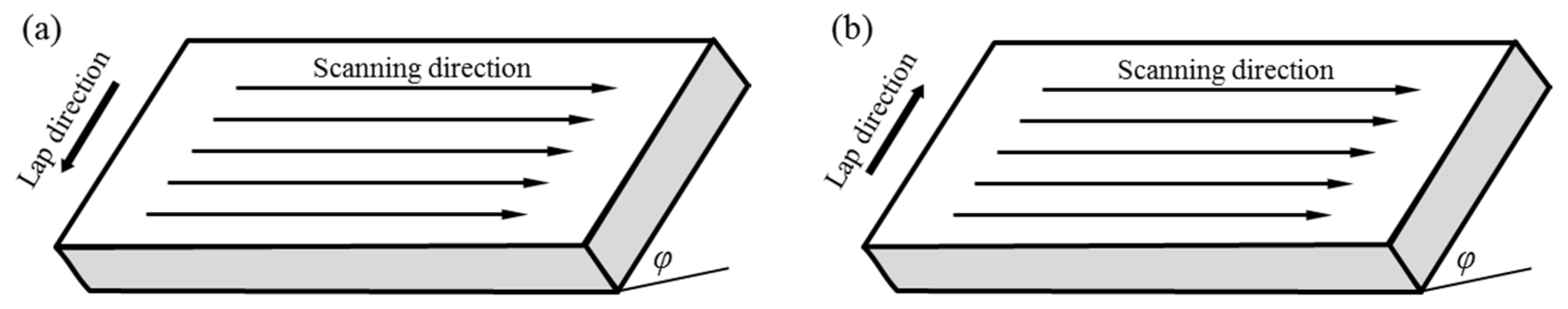
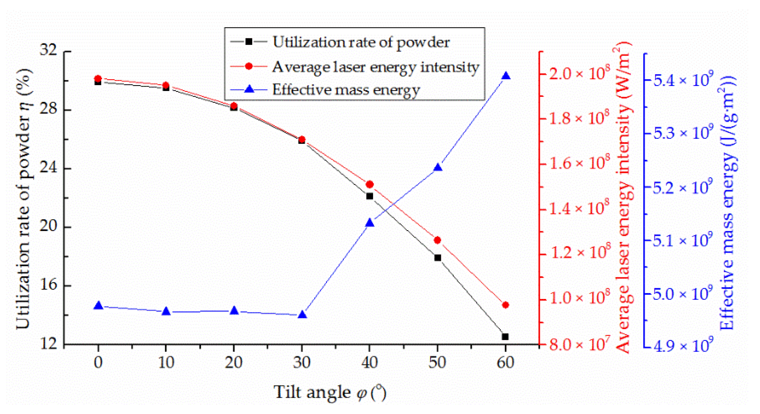
3.1. Laser Intensity Distribution and Energy Attenuation on Tilted Substrate

When the substrate is in a horizontal position for laser cladding, a circular laser spot with a diameter of bc is formed on the surface of the substrate due to the divergence angle 2β. Laser energy intensity of the spot has a Gaussian distribution, which can be expressed as [20]
I ( x , y ) = 2 P π R 0 2 exp [ 2 x 2 + y 2 R 0 2 ]
where P is the laser power and R0 is the characteristic radius of the laser spot on horizontal substrate. According to Equation (1), the energy intensity is the largest at the spot’s center, and the energy intensity decreases with the increasing distance from the spot’s center.
Assume that the influence of the concentration distribution of the powder stream on laser energy is ignored. When the substrate is tilted, the laser spot on the substrate surface becomes elliptical, as shown in Figure 2. The characteristic radius in the X direction (S direction) changes from R0 to R, while the characteristic radius in the Y direction remains unchanged. In this case, laser energy intensity is still in a Gaussian distribution in the elliptical region, and the center of laser energy intensity on the tilted substrate shifts l compared with that on the horizontal substrate. Thus, the short axis of the elliptical spot bc = R0, and the long axis
e f = R 0 [ cos β cos ( φ + β ) + cos β cos ( φ β ) ]
where β is one-half of the divergence angle of the laser beam and φ is the tilt angle of the substrate. The characteristic radius of the laser spot in S direction R = 1 2 e f . Since the scanning path always coincides with the short axis direction of the ellipse, this work only focuses on the laser intensity distribution of the tilted substrate in a direction perpendicular to the scanning path. Therefore, laser intensity distribution I(y,s) on the tilted substrate is
I ( y , s ) = 2 P π R 0 R exp [ 2 s 2 R 2 + 2 y 2 R 0 2 ]
where s is the one-dimensional vector of the coordinate axis on the tilted substrate’s surface. Thus, the relationship between the spot area on the substrate surface and the tilt angle is
S φ = π R 0 2 2 [ cos β cos ( φ + β ) + cos β cos ( φ β ) ]
It can be seen that the spot area increases with the increasing substrate tilt angle, which is in agreement with the experimental observation. Therefore, the average laser energy intensity, i.e., the ratio of laser energy to spot area (P/Sφ), decreases with the increasing tilt angle.
In the laser cladding process, the laser energy will be attenuated because of the scattering and absorption of the laser beam by the powder stream. Since the laser wavelength (1.06 μm) is smaller than the size of the powder particle (70–126 μm), Mie scattering will occur [25]. Assume that the influence of the substrate’s tilt angle on the reflection of laser energy is ignored. The energy attenuation rate of the laser beam is
A = 1 e n S p μ e l 0
where n is the powder concentration, Sp is the projection area of the powder particle, μe is the extinction coefficient and l0 is the distance of the laser through the powder stream. According to Figure 2, the general tendency of l0 increases with the increasing tilt angle.
In this work, the powder is fed by carrier gas synchronously. Assume that powder particles have the same size and uniform distribution, and the influence of gravity and the interaction between particles are ignored. Therefore, the powder particle concentration is [26]
n = 3 V f 4 π r p 3 ρ p v p s n
where Vf is the powder feed rate, rp is the radius of the powder particle, ρ p is the density of the powder particle, vp is the velocity of the powder particle and sn is the cross-sectional area of the laser nozzle.
According to the theory of projection, the projection area Sp of powder particles per unit time on the substrate is
S p = n π r p 2 cos φ
Combined with Equations (5)–(7), the energy attenuation rate can be expressed as
A = 1 e 3 μ e V f l 0 4 r p ρ p v p s n cos φ
It can be seen that the energy attenuation rate increases with the increasing powder feed rate Vf and substrate tilt angle φ. Therefore, the increased tilt angle will partly reduce the utilization rate of laser power.

3.2. Influence of Tilt Angle on Cracking Rate

Unlike the multi-track one-way laser cladding on the horizontal substrate, there are two lap directions on the tilted substrate, i.e., downward lap (the latter cladding track below the previous one) and upward lap (the latter cladding track above the previous one), as shown in Figure 3. The different lap direction has a certain influence on the coating.
As shown in Figure 4, the cracking rate of Ni60A coating increases with the increasing substrate tilt angle. As the tilt angle increases from 0° to 60°, the cracking rate of the coating prepared by upward lap cladding increases 3.5 times, and that of the coating prepared by downward lap cladding increases 4 times. There are two main reasons for this result. Firstly, the average laser energy intensity decreases with the increasing substrate tilt angle, which reduces the gained laser energy of the unit area coating and increases the cooling rate of the molten pool. A large cooling rate not only decreases the rise time of slag and bubble in the molten pool but also reduces the influence of high temperature plastic flow on stress relaxation [27,28], which can increase defects and residual stress of the coating, making the coating more prone to cracking. Secondly, the energy attenuation rate increases with the increasing substrate tilt angle, which reduces the dilution rate (as shown in Figure 5) due to less energy being obtained by the substrate. A low dilution rate can hardly affect the hard precipitates of chromium borides and chromium carbides [29], which reduces the plasticity of the coating and increases the susceptibility to cracking. Therefore, the cracking rate increases with the increase in the substrate tilt angle, with the same process parameters.
When the substrate tilt angle is large (>40°), the cracking rate increases slowly, as shown in Figure 4. In this case, more powder particles skim over the surface of the molten pool rather than fall into it [30]. This results in a rapid decrease in the utilization rate of powder η, which is greater than that of the average laser energy intensity, as shown in Figure 6. Thus, the gained energy of a unit mass powder particle injected into the molten pool increases. In this work, the effective mass energy, i.e., the ratio of the average laser energy intensity P/Sφ to effective powder feed rate Vfe, is used to represent this trend, where Vfe = ηVf. As shown in Figure 6, the effective mass energy increases significantly when the tilt angle is large, which partly counteracts the influence of the increasing substrate tilt angle and causes the cracking rate to increase slowly. While the effective mass energy is small, without an obvious change when the tilt angle is small, so the cracking rate increases rapidly at this stage.
Some SEM fracture morphology images of different angles and different lap directions are shown in Figure 7. Figure 7a shows the fracture morphology when the substrate tilt angle is 0°. For the downward lap cladding, Figure 7b,d shows the fracture morphologies when the substrate tilt angle is 20° and 50°, respectively. For the upward lap cladding, Figure 7c shows the fracture morphology when the substrate tilt angle is 30°. It can be seen that there are some obvious characteristics of non-cleavage (as at the red arrows) at all fractures. This is mainly because hard Cr-rich precipitates and eutectic and amorphous phases are the main hard phases in Ni60A coatings, and the crack in the hard precipitate continues to propagate to break the eutectic and amorphous phases under the residual tensile stress, until a complete crack is formed [31]. Therefore, the substrate tilt angle has no influence on the cracking mechanism of Ni60A coating, and the fracture mode is quasi-dissociation.
As shown in Figure 8, the EDS patterns (a)(b)(c) of the crack fracture correspond to labels (I)(II)(III) in Figure 7c, respectively. Combined with the chemical composition analysis in Table 2, labels (I)(II)(III) are hard Cr-rich precipitates, γ ( Ni ) and eutectic and amorphous phases, respectively. These high hardness Cr-rich precipitates and eutectic phases provide easy routes for crack initiation and propagation.
As shown in Figure 4, the cracking rate of the coating prepared by downward lap cladding is larger than that prepared by upward lap cladding with the same tilt angle, and the difference between them increases with the increasing tilt angle. The main reason is that the laser beam is blocked and reflected by part of the previous track, and the energy loss increases with the increasing size of the previous track in the laser beam range. Compared with the upward lap cladding, there is a larger size of the previous track in the laser beam range in the case of downward lap cladding, as shown in Figure 9. Hence, the downward lap cladding obviously reduces laser energy obtained by the latter track and leads to a larger cracking rate. There is a larger substrate tilt angle, a greater difference in blocking and reflection to laser energy, and a greater difference in the cracking rate between them. When the tilt angle is 60°, the cracking rate of the coating prepared by downward lap cladding is 15% higher than that of the coating prepared by upward lap cladding. In addition, in downward lap cladding, it is difficult to obtain enough powder and energy at the toe of the previous track (label the blue circle in Figure 8) due to its own obstruction of the powder stream and laser beam, which leads to defects such as holes, causing cracks [32]. This is also one of the reasons why the coating prepared by downward lap cladding has a larger cracking rate.

4. Discussion

The main reasons for cracks in a Ni60A coating prepared by laser cladding are excessive residual tensile stress and nonuniformly distributed Cr-rich precipitates. When the residual tensile stress exceeds the fracture strength of the coating, cracks are formed [6]. Due to the difference in thermophysical properties between the substrate and the coating, thermal stress is the main source of residual tensile stress. Compared with the width of the track (about 3.5 mm), the length of the track (30 mm) is much larger. Due to the constraint of the substrate, the stress along the cladding direction is the largest, leading to cracking of the coating.

4.1. Residual Stress of the Coating

The generation of thermal stress in the coating is mainly because of the stage at which the molten pool is cooled from the solidus curve to room temperature. Without considering the plastic deformation, as the thermal expansion coefficient of the coating is greater than that of the substrate, the thermal tensile stress along the cladding direction σ x can be expressed as [13]
σ x = E c E s h s ( α c α s ) Δ T ( 1 μ ) ( E s h s + E c h c )
where μ is the Poisson ratio of the coating, α, E, and h are defined as the coefficient of thermal expansion (CTE), elastic modulus and thickness, respectively, the subscripts c and s represent the coating and the substrate, respectively, and Δ T is the difference between the solidus curve and the room temperature.
In the cooling process, the thermal stress and yield strength increase with the decreasing temperature. When the stress exceeds its yield strength, plastic flow will occur, which releases residual stress inside the coating. Since the coating is with good plastic at elevated temperature, the increased dwell time of the coating at the high temperature can greatly benefit the thermal plastic flow and stress relaxation of the coating. t8−5, the dwell time in the temperature range of 800 °C–500 °C, is an important concept in welding, largely affecting its residual stress. Since the laser cladding is similar to the welding, it is appropriate to study the residual stress in the coating by t8−5, as well [28,33,34]. In this work, t8−5 is applied to represent the dwell time at high temperature to assess the influence of plastic flow on stress relaxation. This influence can be expressed as f(t8−5). As t8−5 is positively correlated with stress relaxation, the residual stress of the coating is
σ r e s = σ x f ( t 8 5 )
Thus, the residual stress is negatively correlated with t8−5. The value of t8−5 can be obtained by empirical formula or experiment. The empirical formula of t8−5 is [35]
t 8 5 = μ 2 P 2 π λ V s ( 1 500 T 0 1 800 T 0 )
where μ 2 is the utilization rate of laser power, λ is the thermal conductivity and T0 is the ambient temperature. As the energy attenuation and substrate reflection energy increase with the increasing substrate tilt angle, the utilization rate of laser power μ 2 decreases, which results in t8−5 decrease, according to Equation (11). The experimental data of t8−5 are obtained by analyzing the molten pool data gained by the infrared thermal imager. Moreover, the same trend can be found in the experimental data, as shown in Figure 10. Fitted data, the relationship between t8−5 and tilt angle φ can be approximatively expressed as
t 8 5 , φ = t 8 5 , 0 × cos φ
where t8−5,φ is the t8−5 value when the substrate tilt angle is φ and t8−5,0 is the t8−5 value when the substrate is horizontal. In this work, t8−5,0 = 0.667 s. When the substrate tilt angle increases to 60°, the value of t8−5 decreases 55%.
Smaller t8−5 will weaken the influence of plastic flow on stress relaxation, which causes the residual stress of the coating to increase with the increasing tilt angle. Therefore, the coating tends to crack more easily when the substrate tilt angle increases.

4.2. Fracture Strength of the Coating

Laser cladding is a cycle process in which powder and substrate are heated from room temperature to melting point and then cooled to room temperature in a very short time. The microscopic residual stress brought on by rapid solidification can reach the yield strength and even the tensile limit of the material, and the local stress concentration can easily cause microscopic defects or even microcracks. These damages determine the properties of the coating, including its fracture strength. According to thermodynamics and the energy balance of classical mechanics, Irwin and Orowan modified the Griffith fracture strength model in relation to material properties and damage, taking the influence of plastic work into account [36].
σ f = E ( 2 γ + γ p ) π C z
where E is the elastic modulus, γ is the surface energy of the material, γp is the plastic work required for the microcrack or microdefect expansion unit length and Cz is the size of microcrack and microdefect. The fracture surface energy γ is adE/100, and ad is the lattice distance of the crystal. The plastic work γp is 2~3 magnitude larger than γ. In the microstructure of Ni60A coating, the hard Cr-rich precipitates of Cr7C3, Cr23C6 and Cr5B3 are interstice compounds with complex close-packed crystal structures, and the lattice distance varies with different crystal systems. Thus, the average lattice distance value is selected for calculation [37,38]. Due to high brittleness and rapid formation, hard Cr-rich precipitates themselves can be regarded as a microscopic defect, so the maximum size of the hard precipitate is the maximum size of the microdefect in the coating.
In addition, the fracture strength of the coating is mainly affected by the dilution rate that determines the Fe content in Ni60A coating. XRD results showed that the Fe element can form a ductile phase, such as Fe3Ni with Ni, and inhibit the hard precipitations such as chromium borides and chromium carbides, reducing the brittleness of the coating [29]. When the Fe content exceeds 40%, the precipitation of primary chromium boride is completely inhibited, and the size of the chromium carbides is greatly reduced. In this case, the hardness of the coating decreases by 40%–50%, and the main hard phase is a eutectic structure with high Fe. As shown in Figure 5, the dilution rate decreases with the increasing tilt angle, resulting in the decrease in Fe content to weaken the inhibition on hard precipitates. The size of hard Cr-rich precipitates is determined by the dilution rate of the coating, which effects the fracture strength. Any cross-section of the coating was selected, and SEM and ImageJ were used to observe and measure the maximum size of the hard precipitate. Since the dilution rates of the coatings prepared by two lap directions’ cladding have the same changing trend and are close in value, the observation results of the two groups are combined in Figure 11, considering the randomness of cross-section selection. As shown in Figure 11, the maximum size of the hard precipitate (i.e., Cz) increases significantly with the increasing substrate tilt angle. When the tilt angle is 60°, Cz increases about 10 times. According to Equation (13), the fracture strength of the coating is reduced to 1/3. Combined with Section 4.1 and Section 4.2, it can be found that the residual stress increases and the fracture strength of the coating decreases as the substrate tilt angle increases, which leads to the increase in the cracking rate of the coating. Therefore, it is helpful to obtain a crack-free coating by selecting the smallest substrate tilt angle possible when preparing a high hardness coating on a tilted substrate.
There are still some limitations in the present method. When studying the influence of the substrate tilt angle on residual stress and fracture strength, there is a lack of corresponding research method and sufficient quantitative research. In the study of residual stress, only the changing rule of residual stress can be obtained, but no specific value and distribution are obtained. Furthermore, this work does not consider the stress and structure of different parts of the cladding layer, which results in differences between study results and the actual cladding. These limitations and deficiencies will be improved on in future studies.

5. Conclusions

In this work, Ni60A coating was prepared by coaxial laser cladding on tilted 45# steel substrates, and the influence of the substrate tilt angles on the cracking rate of Ni60A coating was studied. Some of conclusions can be summarized as follows:
(1)
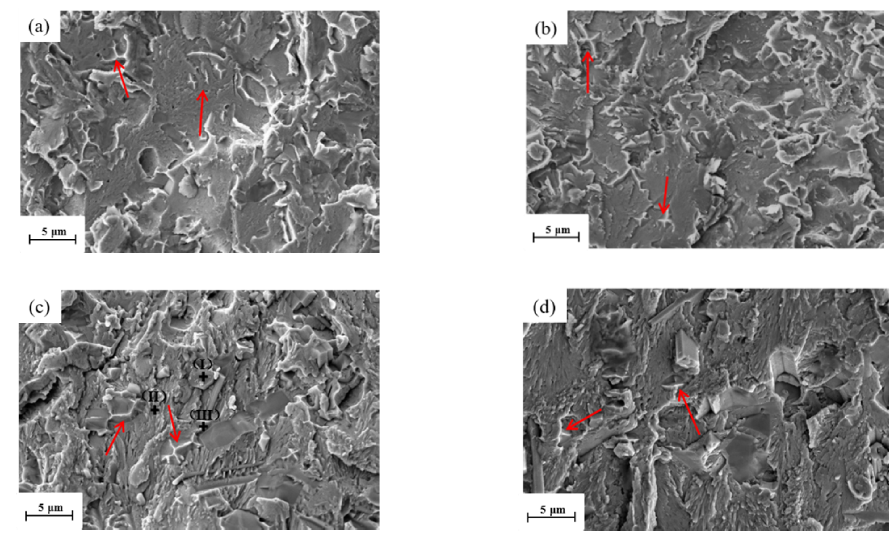
Since the average laser energy intensity decreases and the energy attenuation rate increases with the increasing substrate tilt angle, the energy obtained by the coating decreases, resulting in the increase in cracking rate. As the tilt angle increases from 0° to 60°, the cracking rate of the coating prepared by upward lap cladding increases 3.5 times, and that of the coating prepared by downward lap cladding increases 4 times. The effective mass energy increases significantly when the tilt angle is large, which causes the cracking rate to increase slowly, while the substrate tilt angle has no significant influence on the crack mechanism of Ni60A coating, and the fracture mode is quasi-dissociation.
(2)
As the laser beam is blocked and reflected by the larger size of the previous track, less laser energy is obtained by the latter track in downward lap cladding, which leads to a larger cracking rate than that in the condition of upward lap cladding. The larger the substrate tilt angle, the greater the difference in blocking and reflection of laser energy, and the greater the difference in the cracking rate between them. When the tilt angle is 60°, the cracking rate of the coating prepared by downward lap cladding is 15% higher than that of the coating prepared by upward lap cladding.
(3)
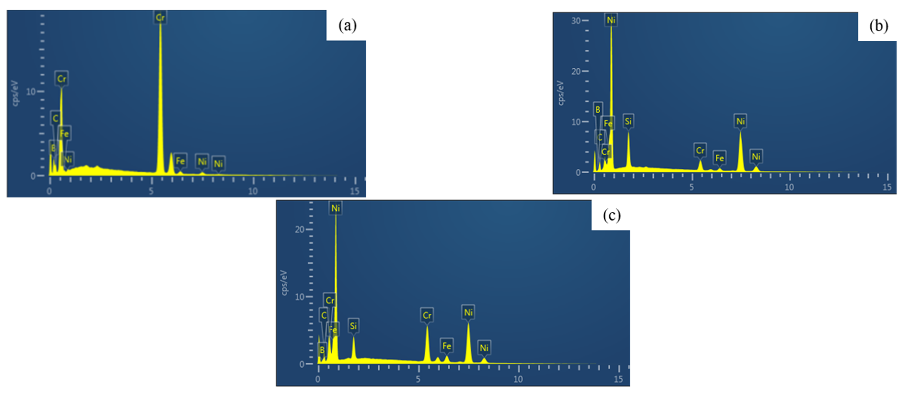
When the substrate tilt angle increases to 60°, the value of t8−5 decreases 55%, which can reduce the influence of plastic flow on stress relaxation and increase the residual stress of the coating. Meanwhile, the maximum size of hard precipitates increases by approximatively 10 times due to the decreased dilution rate, which results in the decreased fracture strength of the coating. These are the main reasons for the increase in the cracking rate of Ni60A coating.

Author Contributions

Conceptualization, B.S. and H.Z. (Hongchao Zhang); Data curation, B.S.; Formal analysis, B.S. and L.D.; Funding acquisition, T.L. and H.Z. (Hongchao Zhang); Investigation, H.Z. (Huan Zhan) and T.L.; Methodology, X.M. and T.L.; Project administration, B.S. and T.L.; Resources, X.M. and T.L.; Supervision, T.L. and H.Z. (Hongchao Zhang); Validation, B.S. and H.Z. (Huan Zhan); Writing—original draft, B.S. and X.M.; Writing—review and editing, B.S. and L.D. All authors have read and agreed to the published version of the manuscript.

Funding

This research was funded by the National Natural Science Foundation of China, grant number 52005081, 51975099.

Institutional Review Board Statement

Not applicable.

Informed Consent Statement

Not applicable.

Data Availability Statement

Not applicable.

Conflicts of Interest

The authors declare no conflict of interest.

Nomenclature

α (1/°C)Coefficient of thermal expansion (CTE)
ad (nm)The lattice distance of the crystal
β (°)One-half of the divergence angle
Cz (mm)The size of microcrack and microdefect
μPoisson ratio of the coating
μe (L/(mol·cm))Extinction coefficient
E (GPa)Elastic modulus
γ (J/m2)The surface energy
γp (J/m2)The plastic work required for microcrack or microdefect expansion unit length
vp (m/s)The velocity of powder particle
h (mm)The thickness
ρ p (kg/m3)The density of powder particle
l0 (mm)The distance of the laser through the powder stream
n (kg/m3)The powder concentration
P (W)Laser power
R (mm)The characteristic radius of the laser spot on horizontal substrate
R0 (mm)The characteristic radius of the laser spot in S direction
Rc (N/mm)Cracking rate
rp (mm)The radius of powder particle
ΔT (°C)The difference between the solidus curve and the room temperature
Sp (mm2)The projection area of the powder particle
Sφ (mm2)Laser spot area
sn (mm2)The cross-sectional area of laser nozzle
t8−5 (s)The dwell time in the temperature range of 800 °C–500 °C
t8−5,φ (s)The t8−5 value when the substrate tilt angle is φ
t8−5,0 (s)The t8−5 value when the substrate is horizontal
ηThe utilization rate of powder
Vf (g/s)Powder feed rate
Vfe (g/s)Effective powder feed rate
φ (°)The tilt angle of the substrate

References

  1. Chen, Z.H.; Li, R.F.; Gu, J.Y.; Zhang, Z.Y.; Tao, Y.W.; Tian, Y.T. Laser cladding of Ni60+17-4PH composite for a cracking-free and corrision resistive coating. Int. J. Mod. Phys. B 2020, 34, 2040042. [Google Scholar] [CrossRef]
  2. Sexton, L.; Lavin, S.; Byrne, G.; Kennedy, A. Laser cladding of aerospace materials. J. Mater. Process. Technol. 2002, 122, 63–68. [Google Scholar] [CrossRef]
  3. Zhang, P.R.; Liu, Z.Q. Machinability investigations on turning of Cr-Ni-based stainless steel cladding formed by laser cladding process. Int. J. Adv. Manuf. Technol. 2016, 82, 1707–1714. [Google Scholar] [CrossRef]
  4. Kusinski, J.; Kac, S.; Kopia, A.; Radziszewska, A.; Rozmus-Górnikowska, M.; Major, B.; Major, L.; Marczak, J.; Lisiecki, A. Laser modification of the materials surface layer—A review paper. Bull. Pol. Acad. Sci. Tech. 2012, 60, 711–728. [Google Scholar] [CrossRef]
  5. Suárez, A.; Amado, J.M.; Tobar, M.J.; Yáñez, A.; Fraga, E.; Peel, M.J. Study of residual stresses generated inside laser cladded plates using FEM and diffraction of synchrotron radiation. Surf. Coat. Technol. 2010, 204, 1983–1988. [Google Scholar] [CrossRef]
  6. Fu, F.X.; Zhang, Y.L.; Chang, G.G.; Dai, J. Analysis on the physical mechanism of laser cladding crack and its influence factors. Optik 2016, 127, 200–202. [Google Scholar] [CrossRef]
  7. de Oliveira, U.; Ocelík, V.; De Hosson, J.T.M. Analysis of coaxial laser cladding processing conditions. Surf. Coat. Technol. 2005, 197, 127–136. [Google Scholar] [CrossRef]
  8. Buet, E.; Braun, J.; Sauder, C. Influence of texture and thickness of pyrocarbon coatings as interphase on the mechanical behavior of specific 2.5D SiC/SiC composites reinforced with hi-nicalon S fibers. Coatings 2022, 12, 573. [Google Scholar] [CrossRef]
  9. Macek, W. Correlation between fractal dimension and areal surface parameters for fracture analysis after bending-torsion fatigue. Metals 2021, 11, 1790. [Google Scholar] [CrossRef]
  10. Niu, F.Y.; Wu, D.J.; Yan, S.; Ma, G.Y.; Zhang, B. Process optimization for suppressing cracks in laser engineered net shaping of Al2O3 ceramics. JOM 2017, 69, 557–562. [Google Scholar] [CrossRef]
  11. Zhou, S.Y.; Su, Y.; Wang, H.; Enz, J.; Ebel, T.; Yan, M. Selective laser melting additive manufacturing of 7xxx series Al-Zn-Mg-Cu alloy: Cracking elimination by co-incorporation of Si and TiB2. Addit. Manuf. 2020, 36, 101458. [Google Scholar] [CrossRef]
  12. Arias-González, F.; del Val, J.; Comesaña, R.; Penide, J.; Lusquiños, F.; Quintero, F.; Riveiro, A.; Boutinguiza, M.; Pou, J. Fiber laser cladding of nickel-based alloy on cast iron. Appl. Surf. Sci. 2016, 374, 197–205. [Google Scholar] [CrossRef]
  13. Hemmati, I.; Ocelík, V.; De Hosson, J.T.M. Effects of the alloy composition on phase constitution and properties of laser deposited Ni-Cr-B-Si coatings. Phys. Procedia 2013, 41, 302–311. [Google Scholar] [CrossRef] [Green Version]
  14. Yu, T.; Deng, Q.L.; Zhang, W.; Dong, G.; Yang, J.G. Study on Cracking Mechanism of Laser Clad NiCrBSi Coating. J. Shanghai Jiaotong Univ. 2012, 46, 1043–1048. [Google Scholar] [CrossRef]
  15. Song, J.L.; Deng, Q.L.; Ge, Z.J.; Chen, C.Y.; Hu, D.J. The cracking control technology of laser rapid forming nickel-based alloys. J. Shanghai Jiaotong Univ. 2006, 40, 548–552. [Google Scholar] [CrossRef]
  16. Lin, Y.H.; Yuan, Y.; Wang, L.; Hu, Y.; Zhang, Q.L.; Yao, J.H. Effect of electric-magnetic compound field on the microstructure and crack in solidified Ni60 alloy. Acta Metall. Sin. 2018, 54, 1442–1450. [Google Scholar] [CrossRef]
  17. Zhou, S.F.; Zeng, X.Y.; Hu, Q.W.; Huang, Y.J. Analysis of crack behavior for Ni-based WC composite coatings by laser cladding and crack-free realization. Appl. Surf. Sci. 2008, 255, 1646–1653. [Google Scholar] [CrossRef]
  18. Marzban, J.; Ghaseminejad, P.; Ahmadzadeh, M.H.; Teimouri, R. Experimental investigation and statistical optimization of laser surface cladding parameters. Int. J. Adv. Manuf. Technol. 2015, 76, 1163–1172. [Google Scholar] [CrossRef]
  19. Tan, H.; Fan, W.; Qian, Y.H.; Chen, Y.G.; Liu, S.Q.; Lin, X. Influence of inclined substrate on process characteristics of directed energy deposition. Opt. Laser Technol. 2020, 129, 106288. [Google Scholar] [CrossRef]
  20. Lin, J.M.; Hwang, B.C. Coaxial laser cladding on an inclined substrate. Opt. Laser Technol. 1999, 31, 571–578. [Google Scholar] [CrossRef]
  21. Zhu, G.X.; Shi, S.H.; Fu, G.Y.; Shi, J.J.; Yang, S.; Meng, W.D.; Jiang, F.B. The influence of the substrate-inclined angle on the section size of laser cladding layers based on robot with the inside-beam powder feeding. Int. J. Adv. Manuf. Technol. 2017, 88, 2163–2168. [Google Scholar] [CrossRef]
  22. Paul, C.P.; Mishra, S.K.; Kumar, A.; Kukreja, L.M. Laser rapid manufacturing on vertical surfaces: Analytical and experimental studies. Surf. Coat. Technol. 2013, 224, 18–28. [Google Scholar] [CrossRef]
  23. Yu, T.B.; Qiao, R.Z.; Han, J.B.; Chen, Y.D.; Ren, H. Residual stress numerical simulation of laser cladding on inclined substrate. Hot Work. Technol. 2020, 49, 75–79. [Google Scholar] [CrossRef]
  24. Huang, Y.J.; Zeng, X.Y. Investigation on cracking behavior of Ni-based coating by laser-induction hybrid cladding. Appl. Surf. Sci. 2010, 256, 5985–5992. [Google Scholar] [CrossRef]
  25. Ren, Z.B.; Lu, Z.W.; Zhu, H.D.; Sun, Q. Study on microsphere light scattering. Infrared Laser Eng. 2004, 33, 401–404. [Google Scholar] [CrossRef]
  26. Li, H.B.; Li, T.; Wang, X.L.; Xu, H.Y.; Zhang, H.C. Study on the influence of the inclined substrate to the energy distribution of laser cladding. Appl. Laser 2017, 37, 333–339. [Google Scholar] [CrossRef]
  27. Hahn, T.A. Thermal stress relaxation due to plastic flow in the fiber coating of a continuous fiber reinforced composite. J. Compos. Mater. 1993, 27, 1545–1577. [Google Scholar] [CrossRef]
  28. Brückner, F.; Lepski, D.; Beyer, E. Modeling the influence of process parameters and additional heat sources on residual stresses in laser cladding. J. Therm. Spray Technol. 2007, 16, 355–373. [Google Scholar] [CrossRef]
  29. Hemmati, I.; Ocelík, V.; De Hosson, J.T.M. Dilution effects in laser cladding of Ni-Cr-B-Si-C hardfacing alloys. Mater. Lett. 2012, 84, 69–72. [Google Scholar] [CrossRef]
  30. Yin, Y.J.; Yang, W.; Liu, J.Y.; Zeng, D.X. The effects of substrate tilt and coaxial nozzle deflection on laser cladding morphology and powder utilization rate. Appl. Laser 2020, 40, 800–805. [Google Scholar] [CrossRef]
  31. Hemmati, I.; Ocelík, V.; De Hosson, J.T.M. Advances in laser surface engineering: Tackling the cracking problem in laser-deposited Ni-Cr-B-Si-C alloys. J. Min. Met. Mat. S. 2013, 65, 741–748. [Google Scholar] [CrossRef]
  32. Zhang, P.; Ma, L.; Yuan, J.P.; Cai, Z.H. Analysis of stress and strain fields of laser cladding process on ring circular orbit. J. Shanghai Jiaotong Univ. 2011, 16, 296–301. [Google Scholar] [CrossRef]
  33. Wang, D.Z.; Hu, Q.W.; Zeng, X.Y. Residual stress and cracking behaviors of Cr13Ni5Si2 based composite coatings prepared by laser-induction hybrid cladding. Surf. Coat. Technol. 2015, 274, 51–59. [Google Scholar] [CrossRef]
  34. Dats, E.P.; Tkacheva, A.V. Technological thermal stresses in the shrink fitting of cylindrical bodies with consideration of plastic flows. J. Appl. Mech. Tech. Phy. 2016, 57, 569–576. [Google Scholar] [CrossRef]
  35. Lazić, V.N.; Sedmak, A.S.; Živković, M.M.; Aleksandrović, S.M.; Čukić, R.D.; Jovičić, R.D.; Ivanović, I.B. Theoretical-experimental determining of cooling time (t8/5) in hard facing of steels for forging dies. Therm. Sci. 2010, 14, 235–246. [Google Scholar] [CrossRef]
  36. Weertman, J. Fracture mechanics: A unified view for Griffith-Irwin-Orowan cracks. Acta Metall. 1978, 26, 1731–1738. [Google Scholar] [CrossRef]
  37. Gong, X.G.; Cui, C.; Yu, Q.; Wang, W.; Xu, W.W.; Chen, L.J. First-principles study of phase stability and temperature-dependent mechanical properties of (Cr, M)23C6 (M = Fe, Mo) phases. J. Alloys Compd. 2020, 824, 153948. [Google Scholar] [CrossRef]
  38. Liu, Y.Z.; Jiang, Y.H.; Zhou, R. First-principles study on stability and mechanical properties of Cr7C3. Rare Met. Mat. Eng. 2014, 43, 2903–2907. [Google Scholar] [CrossRef]
Figure 1. Schematic diagram of the laser cladding process on tilted substrate.
Coatings 12 00966 g001
Figure 2. Gaussian distribution model diagram of laser beam.
Coatings 12 00966 g002
Figure 3. Lap directions: (a) downward; (b) upward.
Coatings 12 00966 g003
Figure 4. Influence of substrate tilt angle on cracking rate.
Coatings 12 00966 g004
Figure 5. Influence of substrate tilt angle on dilution rate.
Coatings 12 00966 g005
Figure 6. Influence of substrate tilt angle on three parameters.
Coatings 12 00966 g006
Figure 7. SEM fracture morphology: (a) 0°; (b) 20°, downward; (c) 30°, upward; (d) 50°, downward.
Coatings 12 00966 g007
Figure 8. EDS patterns of the crack fracture in Figure 7c: (a) hard Cr-rich precipitates; (b) γ ( Ni ) (c) eutectic and amorphous phases.
Coatings 12 00966 g008
Figure 9. Laser beam range of different lap directions: (a) downward; (b) upward.
Coatings 12 00966 g009
Figure 10. Influence of substrate tilt angle on t8−5.
Coatings 12 00966 g010
Figure 11. Influence of substrate tilt angle on hard precipitate size.
Coatings 12 00966 g011
Table 1. Chemical compositions of Ni60A powder and 45# steel substrate (wt.%).
Materials/ElementsCBCrSiMnCuP, SFeNi
Ni60A0.8–1.03.1–3.815.5–17.83.8–4.5---3.5~4.5Bal.
45# steel0.42–0.5-≤0.250.17–0.370.5–0.8≤0.25≤0.045Bal.≤0.25
Table 2. Chemical compositions corresponding to Figure 8 (wt.%).
ElementsNiCrFeSiBC
Figure 8a2.5586.912.176.961.40
Figure 8b80.617.692.506.040.143.03
Figure 8c72.1412.925.633.080.422.88
Publisher’s Note: MDPI stays neutral with regard to jurisdictional claims in published maps and institutional affiliations.

