Article

The Effect of Process-Induced Porosity on Fatigue Properties of Ti6Al4V Alloy via High-Power Direct Energy Deposition

1
Key Laboratory of Advanced Technologies of Materials, Ministry of Education, School of Materials Science and Engineering, Southwest Jiaotong University, Chengdu 610031, China
2
AVIC Chengdu Aircraft Industrial (Group) Co., Ltd., Chengdu 610073, China
*
Authors to whom correspondence should be addressed.
Coatings 2022, 12(6), 822; https://doi.org/10.3390/coatings12060822
Submission received: 14 May 2022 / Revised: 5 June 2022 / Accepted: 9 June 2022 / Published: 11 June 2022
(This article belongs to the Special Issue Laser Cladding Coatings: Microstructure, Properties, and Applications)

Abstract

:
Titanium alloy is widely used in the aviation sector and has become the most important structural material in aircraft manufacturing. However, manufacturing a large-scale titanium component owns a high buy-to-fly ratio due to its poor machinability and expensive price. Over the last decade, the additive manufacturing (AM) technology has developed rapidly and has become a promising processing method for titanium alloys. In the future, in order to enhance processing efficiency and material utilization, a higher laser energy source is supposed to be applied in AM processes. Nevertheless, porosity within the AM fabricated part is the most important issue that restricts the application of AM technology. In the present work, two bulks with different porosities were fabricated using high-power direct energy deposition (HP-DED), and the high cycle fatigue (HCF) performance of the as-build part was tested and compared. The result shows that a lack of fusion (LOF), spherical pores and un-melted particles are the main porosity defects in the as-build part. The shape, size and location of the defect will have a synthetic effect on HCF performance. In addition, the unstable key-hole during the process will facilitate the formation of a pore, which consequently increases the porosity. Online monitoring and closed-loop feedback systems should be established for enhancing the process stability.

1. Introduction:

Titanium alloys are widely used in the aerospace industry due to their high specific strength, superior corrosion resistance and excellent mechanical properties at elevated temperatures. Ti6Al4V alloy is extensively used to manufacture critical structural parts in the aviation sector, such as aircraft frame beam structures, compressor blades, turbine blades, undercarriages and so forth [1]. In recent years, with the rapid development of high-speed transport equipment, the demand for structural components with a higher strength, a higher reliability and a longer service life has increasingly risen.
During the last decade, additive manufacturing (AM) technologies have received extensive interest among researchers since they have various advantages against traditional processing methods in consideration of energy consumption, material utilization and design flexibility [2]. Hence, an increasing number of institutes and enterprises have established their own AM processing systems. However, there are still several issues that restrict the application of AM technologies into actual mass production, such as limited productivity, anisotropic performance, high porosity and poor plasticity.
For metal materials, there are four typical AM technologies: wire arc additive manufactured (WAAM), selective laser melting (SLM), electron beam melting (EBM) and direct energy deposition (DED). Each of them has several nomenclatures by different scholars but share an identical processing principle. It is well known that there are many large-scale titanium components in an aircraft structure. However, manufacturing large-scale titanium parts using traditional methods involves a high buy-to-fly ratio due to the costly price and poor machinability of titanium alloys. In the future, manufacturing large-scale titanium components using AM technologies is of great practical significance in terms of both ecological and economic purpose. Among the common AM technologies, direct energy deposition (DED) is the best candidate, which owns a moderate deposition efficiency and controllable processing accuracy. In the laser cladding process, it is well known that the width and height of a single-track increase with the increase of the applied laser power. Therefore, a higher laser power in the DED process will consequently lead to an enhanced processing efficiency, thus shortening the processing time.
Hitherto, there are limited open literatures in relation to fabricating titanium components using AM technologies with a laser power greater than 4 kw. Ren et al. successfully fabricated a Ti6Al4V part using direct energy deposition with a laser power of 7.6 kw. Afterwards, he conducted a series of investigations regarding fatigue crack growth (FCG) behavior [3] and low cycle fatigue (LCF) performance [4,5]. Wang et al. [6] fabricated a Ti-6.5Al-3.5Mo-1.5Zr part using laser additive manufacturing (LAM) with a laser power of 4–6 kw, and clarified the relationship between microstructural anisotropy and FCG behavior. Brandl fabricated a Ti6Al4V part using wire-feed direct energy deposition with a laser power of 3.5 kw, and systematically studied the microstructure feature [7] and tensile behavior [8] of as-fabricated alloy.
In summary, limited investigations have been carried out regarding the microstructure characterization and fatigue performance of Ti6Al4V as it is part fabricated by HP-DED. Therefore, a deep understanding for the HP-DED process is still needed in terms of microstructure evolution, defect characterization and service performance. In the process of HP-DED, the formation of a keyhole is inevitable due to a higher heat input and subsequent recoil pressure caused by metallic vapor, which is the same as laser welding. The unstable molten pool and keyhole will consequently lead to greater entrapments of gas bubbles and a higher porosity, and could thus deteriorate the fatigue performance.
Processing-induced porosity is the main issue that restricts the application of AM fabricated components [9]. There are three main porosity defects within AM fabricated parts.
A lack of fusion (LOF) occurs due to the insufficient laser energy input between layers, un-melted particles and pores with different shapes due to the entrapped gas bubbles during solidification [10]. The effect of porosity on the fatigue life has been well established through statistical analysis methods in recent years [11,12,13,14,15,16,17], and a corresponding modified Kitagawa-Takahashi diagram has been proposed to predict the fatigue life. In addition, Romali Biswal studied the effect of the pore location on the fatigue performance of AM fabricated Ti6Al4V through finite element analysis [18], and established the relationship between the stress concentration factor and pore shape. The result shows that the oblate spherical pore has the highest stress concentration factor. Moreover, machine learning is also a feasible approach for predicting the fatigue life of AM fabricated parts [19,20].
To the best knowledge of the authors, no investigation has been published to date in relation to the effect of processing-induced porosity on fatigue performance of Ti6Al4V parts fabricated by HP-DED. In the present work, the high cycle fatigue (HCF) performance of HP-DED fabricated Ti6Al4V parts was investigated. The influence of porosity on HCF performance is thoroughly discussed.

2. Experimental Material and Methods

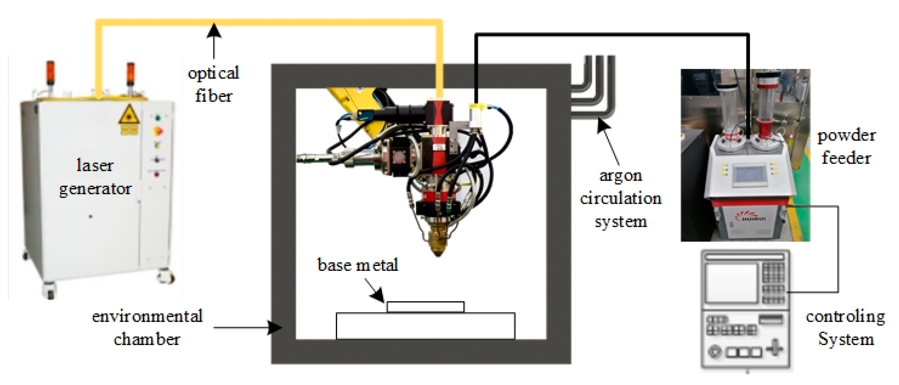
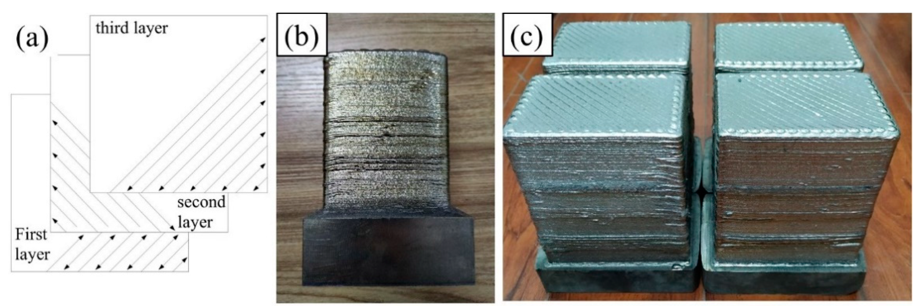
2.1. Manufacturing Procedures

In an enclosed environmental chamber, an additive manufacturing (AM) system was established based on coaxially powder-blown direct energy deposition. Specifically, the AM system consisted of an argon atmosphere protecting chamber with a volume of approximately 20 cubic meters, a laser generator with a maximum output power of 6 kw, a three-axis CNC controlling mechanism, a powder feeder, an argon circulatory system, and an integrated controlling computer. The layout of the whole AM system is schematically shown in Figure 1.
Ti6Al4V wrought plate and Ti6Al4V commercial powder (provided by Xi’an Bright Laser Technologies Co., Ltd., Xi’an, China) were used as a base metal and a feedstock material, respectively. Chemical composition of the powder is characterized by a high-frequency combustion infrared absorption method (C element), inert gas melting thermal conductivity method (O, N, H elements) and an inductively coupled plasma optical emission spectrometer method (other elements), which is listed in Table 1. Prior to the high-power direct energy deposition (HP-DED) process, the circulatory system was activated to pump argon gas into the chamber until the content of oxygen is below 30 ppm. The inner pressure of the chamber was kept slightly higher than the ambient pressure during the manufacturing process. The optimum processing parameters have been determined through previous single-track experiments, which are listed in Table 2. In addition, the scanning direction was kept at 90 degrees between the two successive layers for diminishing the residual stress and deformation, which is shown in Figure 2a.
In order to study the effect of processing-induced porosity on fatigue performance, two batches of powder materials were prepared and one of them was deliberately contaminated. The powder was contaminated by being placed in the ambient environment for several hours without protection. Afterwards, two Ti6Al4V bulks were deposited using original powder and contaminated powder, respectively. For simplicity, the fabricated parts with the contaminated powder and the original powder were denoted as bulk1 and bulk2 in the remaining parts, respectively. The macroscopic morphology of the two bulks in their as-deposited state are shown in Figure 2b,c.

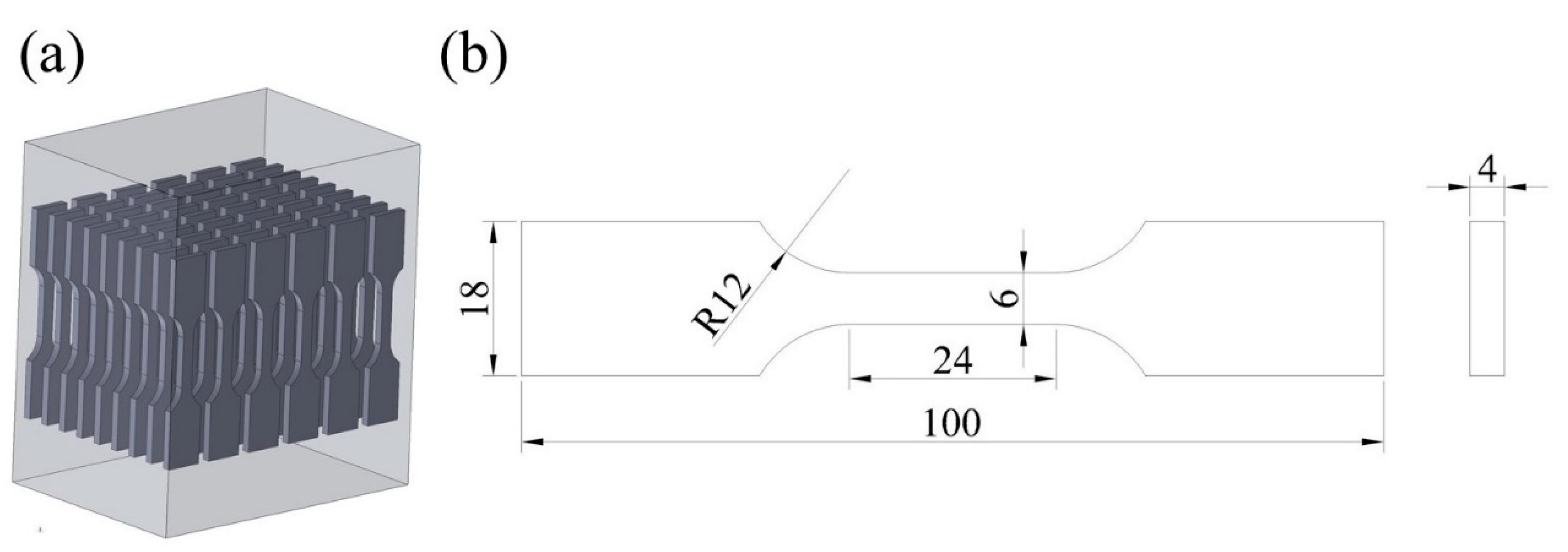
2.2. Microstructure Characterization, Tensile Testing and Fatigue Testing

The fabricated bulks were taken from the chamber after the HP-DED process was finished. Subsequently, the as-deposited bulks were separated from the base metal, and the additional material on the rough surface was removed by milling. The middle section in the height of the fabricated parts was chosen as the representative zone for subsequent characterization.
Specimens used for metallography characterization, tensile testing and high cycle fatigue (HCF) testing were cut by electric discharging machining. Then, the specimen for microstructure observation was prepared according to standard metallographic procedures, including mounting with resin and polishing with silica suspension. Subsequently, the scratches in the specimen were removed with a MIR-EPLAB-01 electrolytic polishing instrument, and then a solution of 5 mL HF, 12 mL HN3O, and 83 mL H2O was used to etch the specimen. The macroscopic morphology and microstructure were observed using a stereo microscope and an optical microscope (ZEISS Observer.A1m, Gottingen, Germany), respectively.
Axial tensile testing was conducted using an electronic universal tester (MTS-CMT5105, MTS, Eden Prairie, MN, USA) at room temperature. During the testing, an extensometer was fixed on the specimen to obtain a more accurate value of deformation. The ultimate tensile strength (UTS), yield strength (YS) and elongation (EI) were calculated by the average value of three specimens. The specimens for HCF testing were cut out along the deposition direction (i.e., height direction), with the sampling configuration and the dimension of the specimen as shown in Figure 3.
Load-controlled axial fatigue tests were conducted using a QBG-100 fatigue tester in air and ambient temperature, with a stress ratio of 0.1 and a frequency range from 80 to 90 Hz. The testing frequency was controlled by the fatigue tester automatically, which is related to the intrinsic property of the material. Referring to ISO 12107-2003, a staircase method and a group method were employed to obtain the fatigue limit and the S-N curve of the HP-DED fabricated Ti6Al4V part, respectively. The mean value and the standard deviation of the fatigue strength were calculated using the following equations.
μ ^ y = S 0 + d ( A C ± 1 2 )
σ ^ y = 1.62 d ( D + 0.029 )
where S 0 is the minimum stress level in the fracture case, d is the stress spacing10 MPa for bulk1 and 20 MPa for bulk2, and A ,   C ,   D are the parameters relating to the testing results. The high cycle fatigue (HCF) testing was interrupted above 107 cycles if the specimen did not fail and if the unbroken specimen was denoted as a “run-out”.
For the group method, the selected stress level for bulk1 is in a range from 300 MPa to 540 MPa, with a spacing of 30 MPa. Two specimens were tested in each stress step in consideration of the limited bulk material. The selected stress level for bulk2 is in a range from 480 MPa to 600 MPa, with a spacing of 30 MPa, and the sample size of each stress step is 6–7. Finally, the S-N curve of the two bulks were depicted according to the results of the group method. The fracture surface of the failed specimens was cut by electric discharging machining (EDM) and was cleaned in anhydrous alcohol ultrasonically. Subsequently, a stereo microscope and a scanning electron microscope (ZEISS Gemini 300, Oberkochen, Germany) were used to observe the fracture morphology. The equivalent diameter of the defect and the distance from the free surface were measured under scanning electron microscope (SEM) for subsequent analysis.

3. Results and Discussion

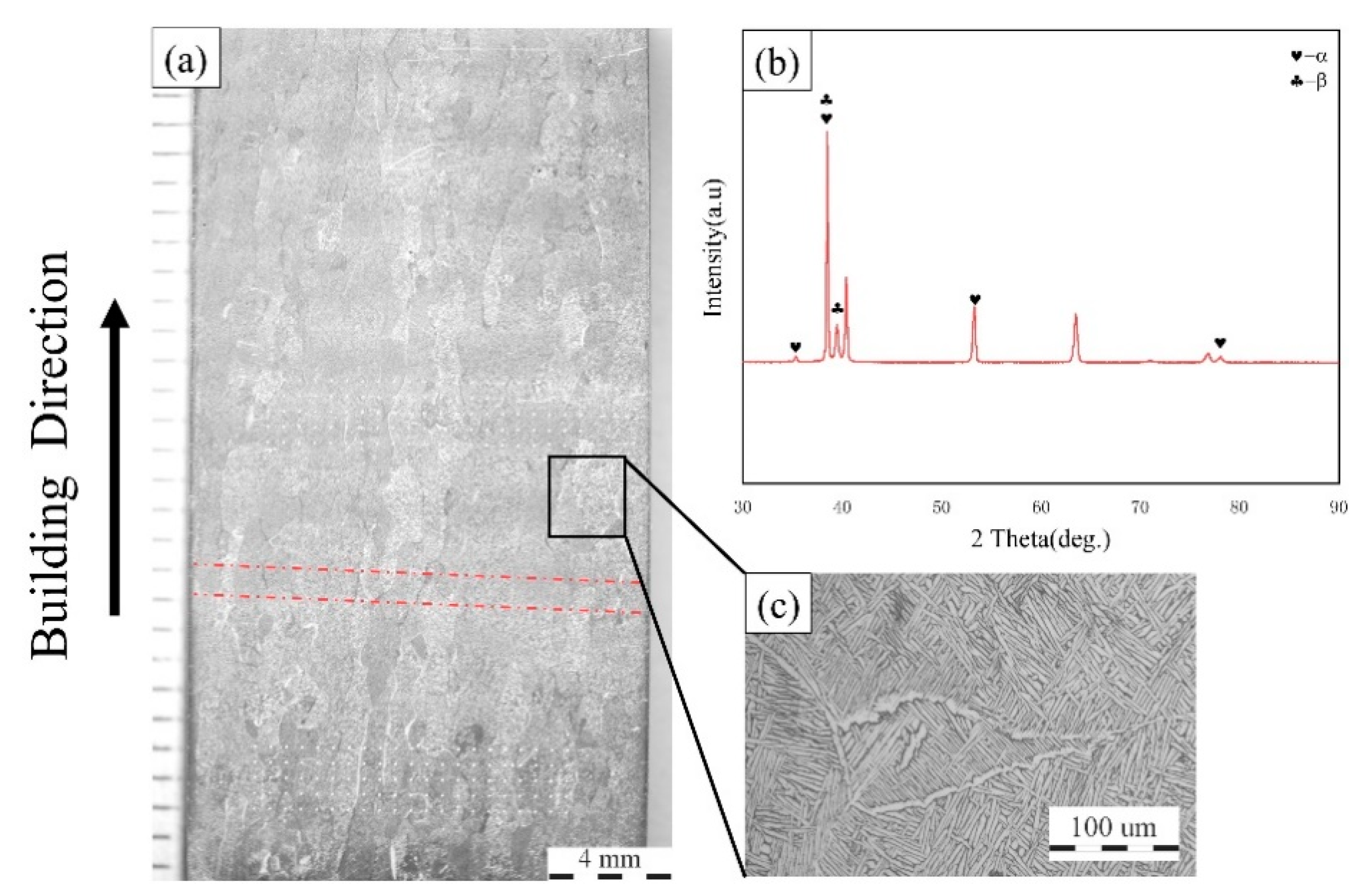
3.1. Microstructure Characterization and Tensile Testing

The oxygen and nitrogen content of the two batches of powder were detected using the ON 3000 type analyzer (NCS TESTING TECHNOLOGY Co., Ltd., Beijing, China), and the results are shown in Table 3. It can be observed that the contaminated powder contains a considerable amount of oxygen and nitrogen elements, which validates the effect of contamination.
Figure 4a shows the typical microstructure of the HP-DED fabricated Ti6Al4V alloy in the XOZ plane. It can be observed that the prior β columnar grains grow epitaxially to the top area, which is the result of directional heat conduction and dissipation. The width and length of β grains can reach hundreds of microns and 4–5 mm, respectively. Meanwhile, the width and length of the prior-β grains in the vertical direction exhibit a heterogeneous distribution, and the morphology of prior-β grains is primarily governed by the thermal conditions during solidification [3]. Interestingly, the longitudinal axis of β grains is not strictly parallel to the deposition direction, but exhibits a certain angle with a maximum value of 20 degrees. This phenomenon has been extensively reported by previous investigations in selective laser melting. Prior β columnar grains with different colors can be ascribed to the different crystallographic orientations within the β columnar grains. In addition, the layer band can also be identified in the panoramic view, which is indicated by the red dash line in Figure 4a. According to Brandl [7], the layer band is the result of alternate reheating and cooling processes during the AM process. Furthermore, the spacing of the layer band does not correspond to the Z axis increment (0.9 mm) during the AM process, since it is related to the thermal history of the material.
Figure 4b shows the XRD result of the microstructure in the middle area of the height direction. The phases within the HP-DED fabricated Ti6Al4V part mainly consist of a hexagonal close-packed α phase and a body-centered cubic β phase. Due to the repeated melting and the rapid cooling of layers, the basket-weave microstructure can be clearly identified and exhibits extreme fine characteristics, as shown in Figure 4c. Meanwhile, a small number of Widmanstätten α-laths could also be observed in the microstructure. Table 4 lists the results of tensile testing, and it can be concluded that the bulk1 demonstrates a higher ultimate tensile strength (UTS) and yield strength (YS) than bulk2, but owns a lower elongation after fracture. The higher UTS of bulk1 may be ascribed to the higher content of oxygen, which can intensify the effect of solution strengthening.

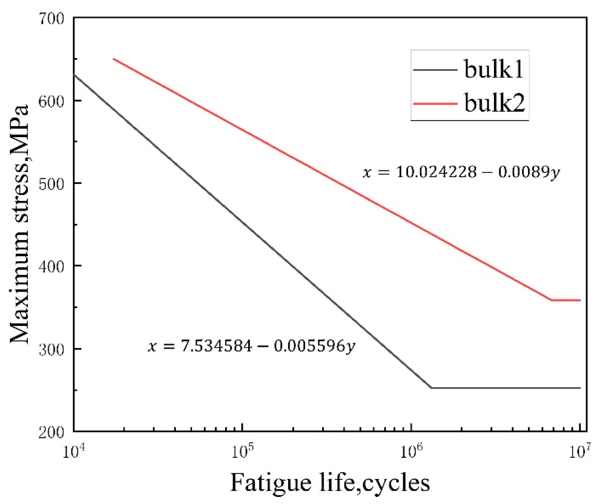
3.2. High Cycle Fatigue Testing

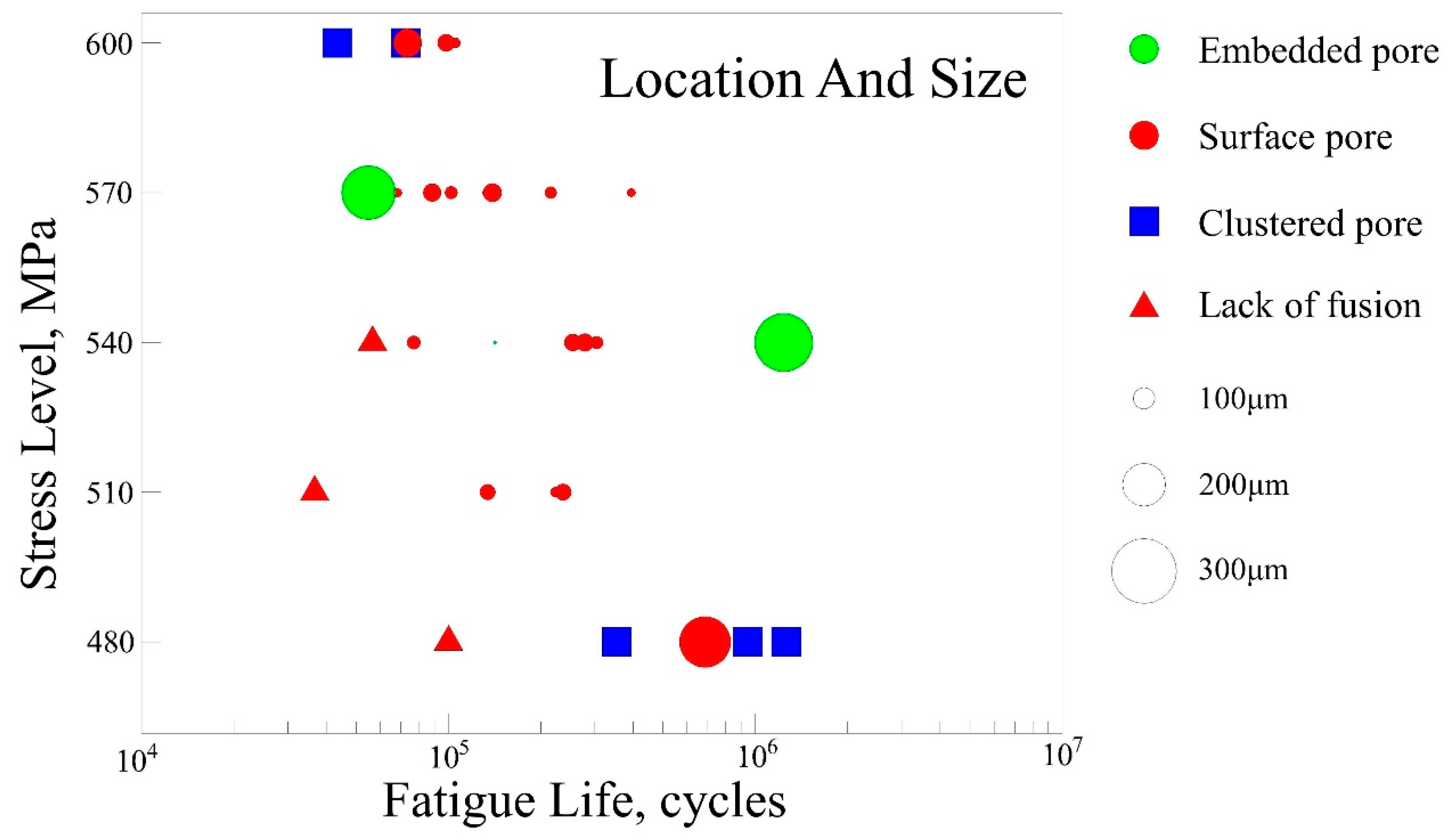
3.2.1. The Effect of Porosity Population

Figure 5 shows the S-N curve according to the staircase method and group method. Table 5 lists the fatigue limit strength and its standard deviation. The formula in Figure 5 shows the relationship between applied maximum stress and fatigue life, and the horizontal asymptote indicates that the fatigue life is infinite. It can be clearly observed that the HCF performance of bulk2 is superior than bulk1. The fatigue limit of bulk2 (358.57 MPa) is much higher than that of bulk1 (252.5 MPa) according to Table 5. In addition, the dispersion of the fatigue strength of bulk1 is larger than that of bulk2, suggesting that the fatigue fracture of bulk1 is more stochastic. The large scatter of HCF testing results for bulk2 can be ascribed to the presence of numerous pores, which can be validated by the subsequent fracture analysis. However, the HCF performance of both bulks is still far away when compared with its wrought counterparts [21].
Figure 6 shows the typical fracture morphology of the failed specimens. It can be clearly seen that the fracture surface of bulk1 contains a large number of pores of different sizes, which is visible to the naked eye under SEM throughout the whole fracture surface. In the meantime, there is no obvious fatigue source region on the fracture surface of bulk1, which can be attributed to the innumerable pores evenly spread over the whole fracture surface. In this case, fatigue microcracks may initiate from multiple defects. Afterwards, the fatigue microcracks propagate and converge to form the main crack, which finally lead to a premature failure. Therefore, there are no typical radical streaks in the fracture surface of bulk1. In addition, a large population of pores reduced the effective bearing area of the specimen, thus meaning that the fatigue strength of bulk1 is much lower than the wrought Ti6Al4V. This detrimental effect will make the engineering design become unfeasible and excessively conservative due to the high dispersion of fatigue life.
In contrast, however, the fracture morphology of bulk2 exhibits a typical fatigue fracture feature. The crack initiated from the pore in the sub-surface and propagated to the peripheral region, as shown in Figure 6b. The boundary between the crack propagation zone and the final fracture zone is distinct, which is indicated by the yellow dash line.
In summary, the contaminated feedstock materials result in a higher porosity within the as-fabricated part, which causes severe damage to the component integrity. Considering the poor fatigue performance of bulk1, the subsequent study will focus on bulk2.

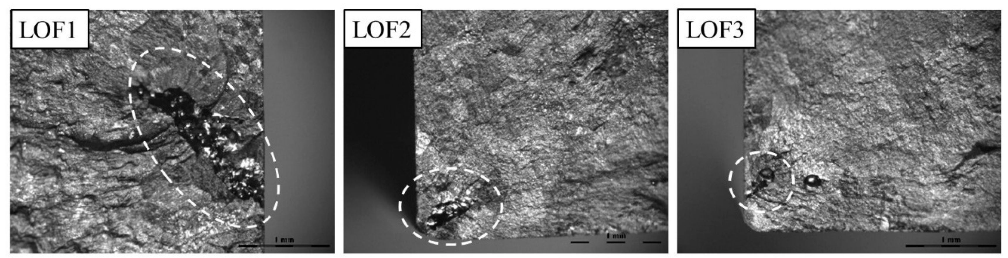
3.2.2. The Effect of Lack of Fusion

In general, there are three common defects within the AM fabricated part: a lack of fusion (LOF), spherical pores and un-melted particles. In the present work, the LOF defects have also been detected on the fracture surface, which is shown in Figure 7 (white dash circles). Meanwhile, some un-melted particles can also be found inside the LOF defects, indicating that the laser energy density is insufficient in local areas. The length of LOF defects and the corresponding fatigue life are listed in Table 6. The LOF defects have a more detrimental effect on fatigue life than spherical pores, since the defect with an irregular shape can act as a stress raiser. The LOF1 specimen has the largest LOF defect, which consequently leads to premature failure, with a fatigue life of 3800 cycles.

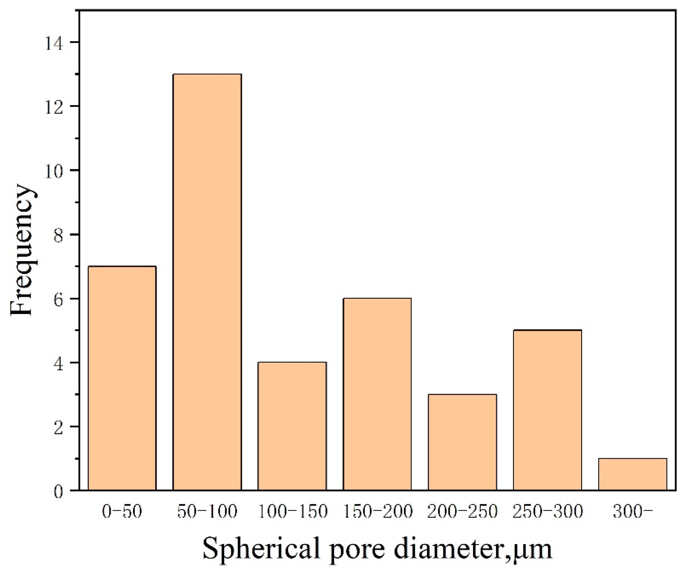
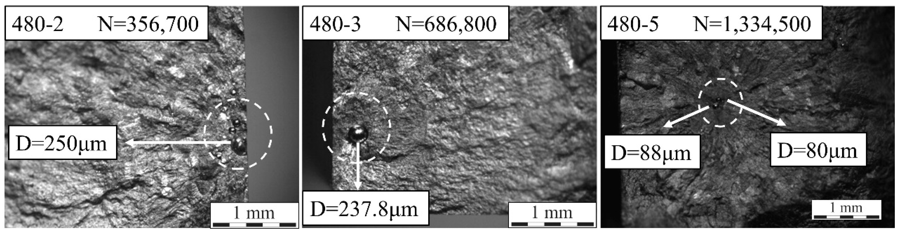
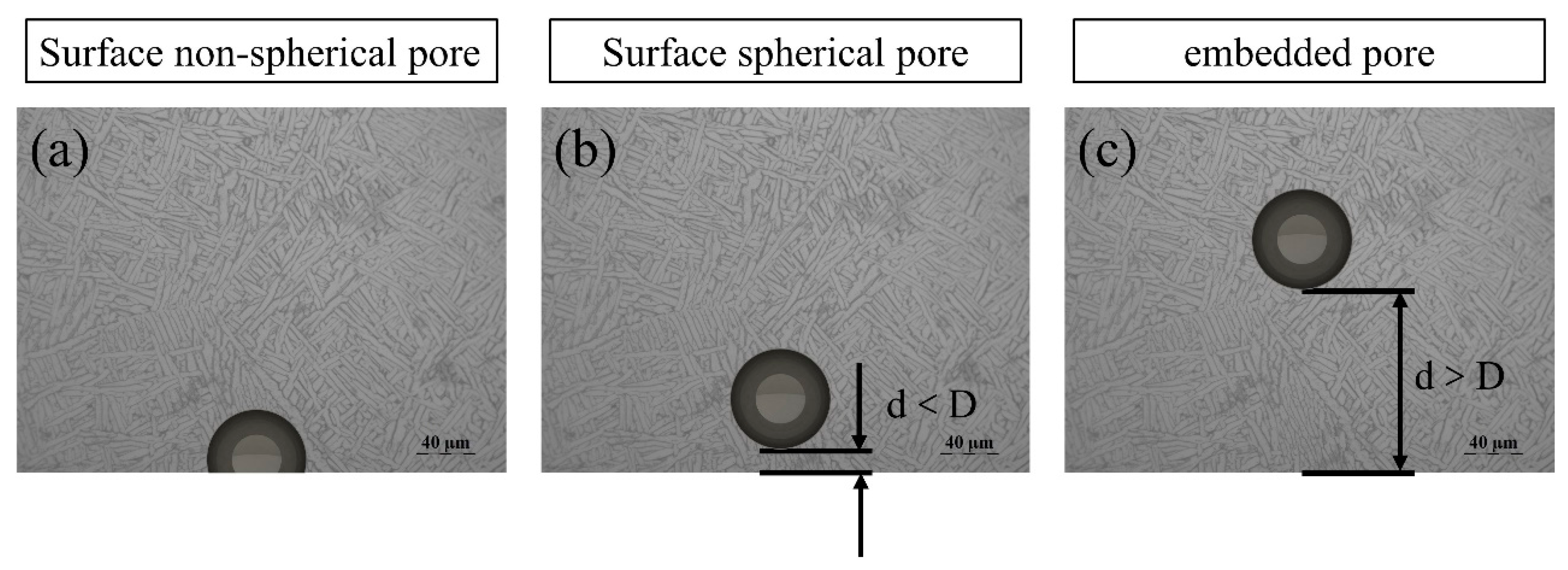
3.2.3. The Effect of Spherical Pores

Another porosity defect within the HP-DED fabricated part is the spherical pores, which is commonly reported in other AM technologies [22,23]. Generally, pores within an AM fabricated part can be classified into three categories: surface pores, embedded pores and clustered pores. Pores that are semi-spherical in shape and are on the surface are classified into “surface pores”, whereas pores with a circular morphology are classified into “embedded pores”. The surface semi-spherical pores were usually formed during the subsequent machining process. In addition, clustered pores were also defect sites that caused fatigue crack initiation in the present study.
Figure 8 presents the conventional S–N format, including the information of the applied maximum stress and the corresponding fatigue life. Meanwhile, the unique symbols are made to represent the crack initiating type and defect size, respectively. The equivalent diameter of the pores was calculated under the scanning electron microscope according to the measured areas of defects. Figure 9 shows the statistical data of the equivalent diameter for different pores that cause fatigue crack initiation.
The specimens with LOF defects have the lowest fatigue life compared with other specimens under the same maximum stress, which can be observed in Figure 8 (indicated by triangle symbols). Except for the specimens with LOF defects, the fatigue cracks within other specimens are all initiated from pores or clustered pores, which is marked with circle or box icons in Figure 8. Interestingly, it can be observed from Figure 8 that the average fatigue life under each stress level did not present a linear relationship with the reduction of maximum stress. For instance, the largest fatigue life under 510 MPa is 241,300 cycles, which is lower than that of 540 MPa and 570 MPa. This can be attributed to the stochastic characteristics of the pore distribution and the intrinsic fatigue nature, which is also reported in many other literatures [24].
Under a lower stress level (480 MPa), it can be observed that the fatigue crack of three specimens is initiated from clustered pores. However, a fatigue crack initiated from the clustered pores did not mean that the specimen presented a lower fatigue life than specimens with isolated pores. Other factors, such as pore size and pore location, can also have a significant influence on fatigue life. Figure 10 shows the fracture morphology of different specimens under a 480 MPa stress level, with their fatigue life (cycles) and the diameter of pores (µm) also included in the figure. It can be clearly observed that the 480-2 specimen exhibits a fracture morphology with both surface pores and clustered pores, which contributes to the lowest fatigue life. However, although the 480-5 specimen has clustered pores, it has the largest fatigue life, since the pores exhibit a smaller size and a larger distance from the free surface.
It is notable that the majority of the pores which contribute to the fatigue crack initiation can be classified into surface pores, which are indicated by the red solid circles in Figure 8. The larger the porosity the as-fabricated part owns, the larger the probability of the formation of surface pores during the post-processing machining. Therefore, it can be concluded that the porosity of the bulk2 is relatively high compared with the Ti6Al4V part fabricated by the selective laser melting (SLM) method, which can realize a porosity lower than 0.5% or even a near-full dense part after a hot isostatic pressing (HIP) post treatment was applied [25]. In order to characterize the porosity of the HP-DED fabricated part quantitatively, an Archimedes drainage method was employed and the result shows that the porosity of bulk2 is 2.2%. Therefore, feasible measures for porosity inhibition should be proposed in future work.
When attention is concentrated on the fatigue failure, which is initiated from a surface pore, it can be found in Figure 8 that the larger pore usually results in a lower fatigue life, which is consistent with the fracture mechanics theory. In addition, a dispersion of fatigue life up to one order of magnitude can be observed, which has also been reported by many other researchers [11,26].

3.2.4. Discussion

As we have discussed in the previous section, a lack of fusion (LOF) has a detrimental effect on the component integrity of AM fabricated parts. The reason for the formation of LOF can be attributed to the process instability and improper processing parameters. During the HP-DED process, the actual laser output power was monitored by accessories within the laser generator and the results can be observed on the computer screen. The actual laser power during the HP-DED process fluctuated near the preset value (i.e., 4 kW) rather than being maintained at a stable value. The unstable laser power may lead to an unstable molten pool. Therefore, the unstable overlapping behavior and interlayer fusion process consequently resulted in the incomplete fusion of Ti6Al4V particles. Although the subsequent processing reheated the precious layer, the energy input was insufficient to eliminate LOF defects.
When attention was concentrated on the surface pore, it can be observed from Figure 8 that some specimens with a larger pore present a longer fatigue life than specimens with smaller pores. This can be ascribed to the classification method in the present study. According to ref. [27], if the distance between the pore and free surface is less than one diameter of the pore, the pore should also be classified as “surface pores” as well. Therefore, there are two kinds of surface pore in Figure 8 (i.e., surface pore with a non-spherical shape and sub-surface pore with a spherical shape), which is schematically shown in Figure 11. It should be mentioned that the pore in Figure 11 is not a genuine pore, but just a sketch map for illustration.
In previous literatures [19,28], it is well acknowledged that the surface incomplete pores (Figure 11a) have a more detrimental effect on fatigue performance than surface spherical pores (Figure 11b). Therefore, some pores have a relatively smaller size but this is located in the outmost surface, resulting in a decreased fatigue life compared with the specimens with larger ones. Under the same circumstances, pores at the surface can lead to a severer stress concentration, facilitating the initiation and propagation of fatigue cracks. In the same way, this explanation is also suitable for the HP-DED fabricated part, as smaller surface pores have been shown to be more detrimental than larger embedded pores.
In general, there are three main factors that lead to the formation of pores: feedstock material, ambient gas entrapment and the key-hole effect. A key-hole will form in the molten pool during the HP-DED process due to an elevated laser energy density, which is the same as the laser welding process. The stability of the key-hole has a significant influence on the defect formation and microstructure evolution of the HP-DED process. Heat accumulation is a typical phenomenon that occurs during the HP-DED process for titanium alloys. It is well known that the titanium alloys have a relatively low thermal conductivity compared with other metal materials. Therefore, the heat dissipation is insufficient in the interface between the base plate and the deposited part, which leads to an elevated temperature of the deposited part. Subsequently, the molten pool will become larger and deeper under the same laser power due to the pre-heated effect. Consequently, the predefined scanning strategy will become inapplicable and the key-hole will become more unstable. Figure 12 shows the schematic of the pore formation mechanism, the periodic enlargement and closure of the key-hole will lead to gas entrapment, thus increasing the porosity of the as-fabricated part. In future research, the coaxial on-line monitoring and closed-loop feedback system may be a feasible approach for solving this issue.

4. Conclusions

In the present work, two bulks with different porosities were fabricated by high-power direct energy deposition (HP-DED). Afterwards, the microstructure feature and high cycle fatigue (HCF) performance of the as-build part were characterized and tested. The effect of processing-induced porosity on the HCF performance was systematically discussed, and the following conclusions can be drawn:
(1)
The microstructure feature of HP-DED fabricated Ti6Al4V is similar to the other AM technologies, which mainly consist of basket-weave microstructure and an α colony within elongated prior β columnar grains.
(2)
The porosity of the as-build part using contaminated powder is extremely large, which consequently leads to an inferior HCF performance compared with parts fabricated with original powder. The HCF performance of both bulks is far from its wrought counterpart.
(3)
The fatigue strength of the Ti6Al4V part fabricated with original powder is approximately 358.57 MPa. Lack of fusion, spherical pores and un-melted particles are the main porosity defects in the HP-DED fabricated Ti6Al4V part.
(4)
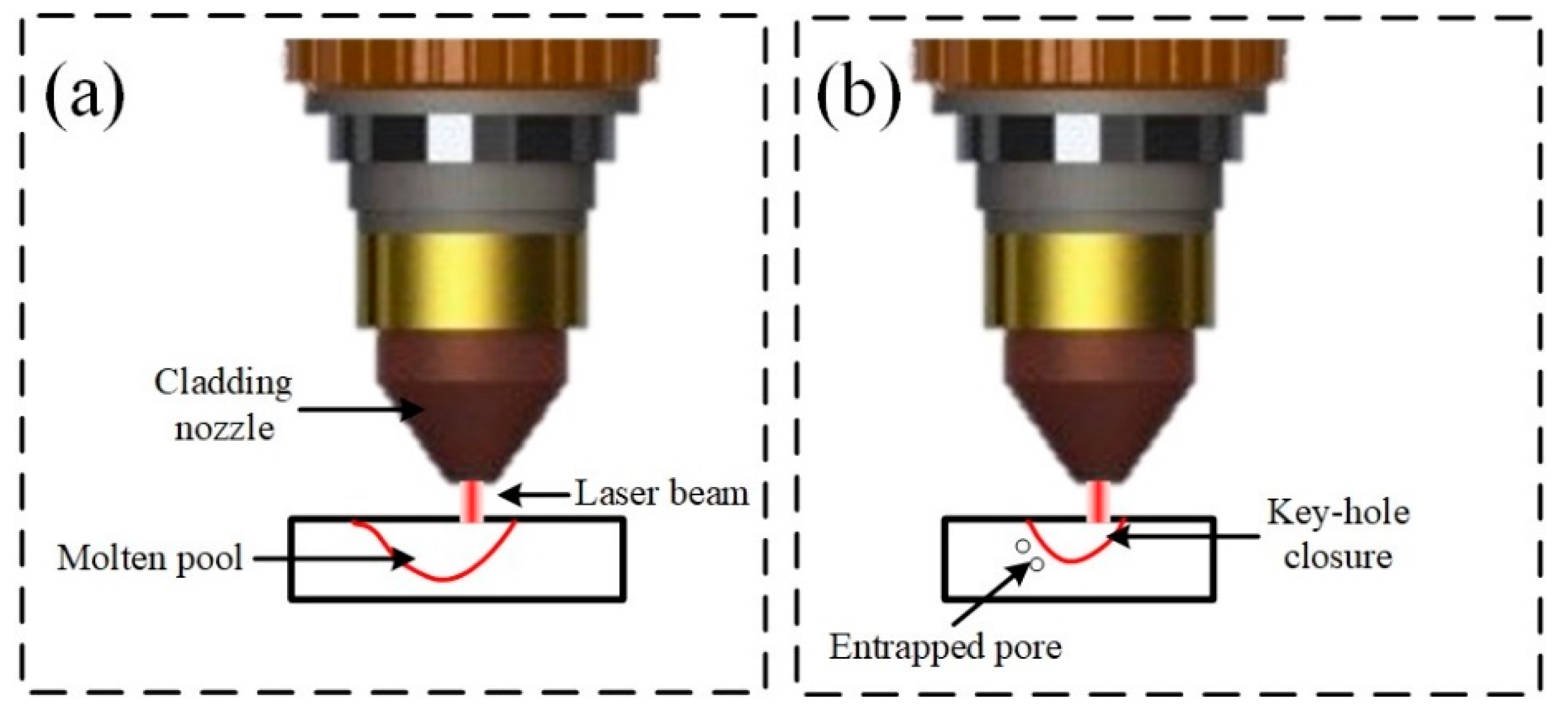
The high-power laser will increase the instability of the molten pool and key-hole, which further leads to a higher porosity in the as-build part. Future research will concentrate on the processing monitoring and closed-loop controlling of the HP-DED process. In addition, feasible measures should be proposed to reduce the porosity in the as-build part of the HP-DED process.

Author Contributions

Conceptualization, H.L., Z.Z. and Y.L.; Data curation, J.L. and Y.C.; Formal analysis, Z.Z. and Y.C.; Funding acquisition, H.H.; Investigation, H.L. and J.L.; Project administration, H.H. and J.C.; Resources, H.H.; Software, J.C.; Supervision, Y.L. and H.C.; Validation, H.C.; Visualization, H.L. and Z.Z.; Writing—original draft, H.L.; Writing—review and editing, Z.Z. and Y.L. All authors have read and agreed to the published version of the manuscript.

Funding

This research was funded by the Sichuan Science and Technology Program (2021YJ0004).

Institutional Review Board Statement

Not applicable.

Informed Consent Statement

Not applicable.

Data Availability Statement

The raw/processed data required to reproduce these findings cannot be shared at this time as the data also forms part of ongoing research.

Acknowledgments

The authors would like to thank Bin Li and Tao Yi from AVIC Chengdu Aircraft Industrial (Group) Co., Ltd. (Chengdu, China) for the device support.

Conflicts of Interest

The authors declare no conflict of interest.

References

  1. Xu, R.D.; Yu, H.C. Effects of Building Orientation on Fatigue Behavior of Ti-6Al-4V Alloy Produced by Selective Laser Melting. Key Eng. Mater. 2019, 795, 208–214. [Google Scholar] [CrossRef]
  2. Azarniya, A.; Colera, X.G.; Mirzaali, M.J.; Sovizi, S.; Bartolomeu, F.; Weglowski, M.K.S.; Wits, W.W.; Yap, C.Y.; Ahn, J.; Miranda, G.; et al. Additive manufacturing of Ti–6Al–4V parts through laser metal deposition (LMD): Process, microstructure, and mechanical properties. J. Alloy. Comp. 2019, 804, 163–191. [Google Scholar] [CrossRef]
  3. Ren, Y.; Lin, X.; Jian, Z.; Peng, H.; Huang, W. Long fatigue crack growth behavior of Ti–6Al–4V produced via high-power laser directed energy deposition. Mater. Sci. Eng. A 2021, 819, 141392. [Google Scholar] [CrossRef]
  4. Ren, Y.M.; Lin, X.; Guo, P.F.; Yang, H.O.; Tan, H.; Chen, J.; Li, J.; Zhang, Y.Y.; Huang, W.D. Low cycle fatigue properties of Ti-6Al-4V alloy fabricated by high-power laser directed energy deposition: Experimental and prediction. Int. J. Fatigue 2019, 127, 58–73. [Google Scholar] [CrossRef]
  5. Ren, Y.M.; Lin, X.; Yang, H.O.; Tan, H.; Chen, J.; Jian, Z.Y.; Li, J.Q.; Huang, W.D. Microstructural features of Ti-6Al-4V manufactured via high power laser directed energy deposition under low-cycle fatigue. J. Mater. Sci. Technol. 2021, 83, 18–33. [Google Scholar] [CrossRef]
  6. Wang, Y.; Chen, R.; Cheng, X.; Zhu, Y.; Zhang, J.; Wang, H. Effects of microstructure on fatigue crack propagation behavior in a bi-modal TC11 titanium alloy fabricated via laser additive manufacturing. J. Mater. Sci. Technol. 2019, 35, 403–408. [Google Scholar] [CrossRef]
  7. Brandl, E.; Schoberth, A.; Leyens, C. Morphology, microstructure, and hardness of titanium (Ti-6Al-4V) blocks deposited by wire-feed additive layer manufacturing (ALM). Mater. Sci. Eng. A 2012, 532, 295–307. [Google Scholar] [CrossRef]
  8. Brandl, E.; Palm, F.; Michailov, V.; Viehweger, B.; Leyens, C. Mechanical properties of additive manufactured titanium (Ti–6Al–4V) blocks deposited by a solid-state laser and wire. Mater. Des. 2011, 32, 4665–4675. [Google Scholar] [CrossRef]
  9. Tshephe, T.S.; Akinwamide, S.O.; Olevsky, E.; Olubambi, P.A. Additive manufacturing of titanium-based alloys-A review of methods, properties, challenges, and prospects. Heliyon 2022, 8, e09041. [Google Scholar] [CrossRef]
  10. Li, E.; Zhou, Z.; Wang, L.; Shen, H.; Zou, R.; Yu, A. Particle scale modelling of melt pool dynamics and pore formation in selective laser melting additive manufacturing. Powder Technol. 2022, 397, 117012. [Google Scholar] [CrossRef]
  11. Akgun, E.; Zhang, X.; Biswal, R.; Zhang, Y.; Doré, M. Fatigue of wire+arc additive manufactured Ti-6Al-4V in presence of process-induced porosity defects. Int. J. Fatigue 2021, 150, 106315. [Google Scholar] [CrossRef]
  12. Biswal, R.; Zhang, X.; Syed, A.K.; Awd, M.; Ding, J.; Walther, F.; Williams, S. Criticality of porosity defects on the fatigue performance of wire + arc additive manufactured titanium alloy. Int. J. Fatigue 2019, 122, 208–217. [Google Scholar] [CrossRef] [Green Version]
  13. Hu, Y.N.; Wu, S.C.; Wu, Z.K.; Zhong, X.L.; Ahmed, S.; Karabal, S.; Xiao, X.H.; Zhang, H.O.; Withers, P.J. A new approach to correlate the defect population with the fatigue life of selective laser melted Ti-6Al-4V alloy. Int. J. Fatigue 2020, 136, 105584. [Google Scholar] [CrossRef]
  14. Li, W.B.; Pang, J.C.; Zhang, H.; Li, S.X.; Zhang, Z.F. The high-cycle fatigue properties of selective laser melted Inconel 718at room and elevated temperatures. Mater. Sci. Eng. A 2022, 836, 142716. [Google Scholar] [CrossRef]
  15. Liu, F.; He, C.; Chen, Y.; Zhang, H.; Wang, Q.; Liu, Y. Effects of defects on tensile and fatigue behaviors of selective laser melted titanium alloy in very high cycle regime. Int. J. Fatigue 2020, 140, 105795. [Google Scholar] [CrossRef]
  16. Deng, K.; Wei, H.; Liu, W.; Zhang, M.; Zhao, P.; Zhang, Y. Probabilistic-based random maximum defect estimation and defect-related fatigue life prediction for laser direct deposited 316L parts. J. Mater. Process. Technol. 2022, 299, 117389. [Google Scholar] [CrossRef]
  17. Tang, D.; He, X.; Wu, B.; Wang, X.; Wang, T.; Li, Y. The effect of porosity defects on the mid-cycle fatigue behavior of directed energy deposited Ti-6Al-4V. Theor. Appl. Fract. Mech. 2022, 119, 103322. [Google Scholar] [CrossRef]
  18. Biswal, R.; Syed, A.K.; Zhang, X. Assessment of the effect of isolated porosity defects on the fatigue performance of additive manufactured titanium alloy. Addit. Manuf. 2018, 23, 433–442. [Google Scholar] [CrossRef]
  19. Luo, Y.W.; Zhang, B.; Feng, X.; Song, Z.M.; Qi, X.B.; Li, C.P.; Chen, G.F.; Zhang, G.P. Pore-affected fatigue life scattering and prediction of additively manufactured Inconel 718: An investigation based on miniature specimen testing and machine learning approach. Mater. Sci. Eng. A 2021, 802, 140693. [Google Scholar] [CrossRef]
  20. Zhan, Z.; Hu, W.; Meng, Q. Data-driven fatigue life prediction in additive manufactured titanium alloy: A damage mechanics based machine learning framework. Eng. Fract. Mech. 2021, 252, 107850. [Google Scholar] [CrossRef]
  21. Gerhard, W.; Boyer, R.R.; Collings, E.W. Materials Properties Handbook: Titanium Alloys; ASM International: Almere, The Netherlands, 1994. [Google Scholar]
  22. Wang, X.; Meng, Q.; Hu, W. Continuum damage mechanics-based model for the fatigue analysis of welded joints considering the effects of size and position of inner pores. Int. J. Fatigue 2020, 139, 105749. [Google Scholar] [CrossRef]
  23. Wu, Z.; Kou, H.; Chen, N.; Zhang, Z.; Qiang, F.; Fan, J.; Tang, B.; Li, J. Microstructural influences on the high cycle fatigue life dispersion and damage mechanism in a metastable β titanium alloy. J. Mater. Sci. Technol. 2021, 70, 12–23. [Google Scholar] [CrossRef]
  24. Zhan, Z.; Ao, N.; Hu, Y.; Liu, C. Defect-induced fatigue scattering and assessment of additively manufactured 300M-AerMet100 steel: An investigation based on experiments and machine learning. Eng. Fract. Mech. 2022, 264, 108352. [Google Scholar] [CrossRef]
  25. Rans, C.; Michielssen, J.; Walker, M.; Wang, W.; Hoen-Velterop, L.T. Beyond the orthogonal: On the influence of build orientation on fatigue crack growth in SLM Ti-6Al-4V. Int. J. Fatigue 2018, 116, 344–354. [Google Scholar] [CrossRef]
  26. Ferro, P.; Fabrizi, A.; Berto, F.; Savio, G.; Meneghello, R.; Rosso, S. Defects as a root cause of fatigue weakening of additively manufactured AlSi10Mg components. Theor. Appl. Fract. Mech. 2020, 108, 102611. [Google Scholar] [CrossRef]
  27. Pineau, A.; Antolovich, S.D. Probabilistic approaches to fatigue with special emphasis on initiation from inclusions. Int. J. Fatigue 2016, 93, 422–434. [Google Scholar] [CrossRef]
  28. Wang, J.; Zhang, M.; Wang, B.; Tan, X.; Wu, W.J.; Liu, Y.; Bi, G.J.; Tor, S.B.; Liu, E. Influence of surface porosity on fatigue life of additively manufactured ASTM A131 EH36 steel. Int. J. Fatigue 2021, 142, 105894. [Google Scholar] [CrossRef]
Figure 1. Diagrammatic sketch of the HP-DED system.
Coatings 12 00822 g001
Figure 2. (a) Scanning strategy between layers; macroscopic morphology of (b) bulk1; (c) bulk2.
Coatings 12 00822 g002
Figure 3. (a) Sampling configuration for HCF specimens; (b) dimension of the HCF specimen.
Coatings 12 00822 g003
Figure 4. (a) Macroscopic morphology of high-power DED bulk; (b) XRD result of the black box area in (a); (c) enlarged view of the microstructure.
Coatings 12 00822 g004
Figure 5. S-N curve for bulk1 and bulk2.
Coatings 12 00822 g005
Figure 6. Typical fracture morphology of failed specimen cut from (a) bulk1; (b) bulk2.
Coatings 12 00822 g006
Figure 7. Lack of fusion defects in the fracture morphology of HP-DED.
Coatings 12 00822 g007
Figure 8. HCF test results with a stress ratio of 0.1, tested in air and ambient temperature. The circles are scaled to the size of the pore diameter (µm).
Coatings 12 00822 g008
Figure 9. The statistical distribution of the equivalent diameter for pores.
Coatings 12 00822 g009
Figure 10. Fracture morphology of different specimens under a 480 MPa stress level.
Coatings 12 00822 g010
Figure 11. Schematic of pore classification. (a) the surface incomplete pore; (b)the surface spherical pore; (c) the embedded pore.
Coatings 12 00822 g011
Figure 12. The formation of pores due to the unstable key-hole. (a) the enlargement of the key-hole; (b) the closure of the key-hole.
Coatings 12 00822 g012
Table 1. Chemical composition of Ti6Al4V feedstock powder.
ElementCONHAlVFeTi
Content0.0050.0620.0060.00286.113.970.194Bal.
Table 2. Optimum processing parameters of the HP-DED process.
Laser Power (W)Scanning Speed (mm/min) Powder Feeding Rate (g/min)Layer Thickness (mm)Overlapping Ratio
40001200 (inner hatching) 800 (Contour scanning)310.950%
Table 3. Oxygen and nitrogen content of the contaminated powder and original powder.
ElementContaminated PowderOriginal Powder
Oxygen0.10464%0.02421%
Nitrogen0.00785%0.00188%
Table 4. The results of tensile testing for HP-DED fabricated Ti6Al4V.
StateUltimate Tensile Strength (MPa)Yield Strength (MPa)Elongation (%)
Bulk11033.33951.676.74
Bulk2933.76825.679.99
Table 5. Results of the HCF testing data.
Mean Value of Fatigue StrengthStandard Deviation
Bulk1252.5 MPa64.2573 MPa
Bulk2358.57 MPa8.87 MPa
Table 6. Statistical data of fatigue specimens with a lack of fusion.
Specimen No.Maximum Defect Length (mm)Stress Level (MPa)Fatigue Life (N)
LOF11.83 mm3803800
LOF20.6 mm51037,100
LOF30.4 mm480100,200
Publisher’s Note: MDPI stays neutral with regard to jurisdictional claims in published maps and institutional affiliations.

