Article

On the Impact of Surface Morphology and Transfer Film on Brake System Performance of High-Capacity Metro Train

1
CRRC Changchun Australia Rail Pty Ltd., Melbourne, VIC 3000, Australia
2
Department of Engineering, RMIT University, Melbourne, VIC 3000, Australia
*
Author to whom correspondence should be addressed.
Coatings 2022, 12(7), 894; https://doi.org/10.3390/coatings12070894
Submission received: 12 May 2022 / Revised: 9 June 2022 / Accepted: 20 June 2022 / Published: 24 June 2022
(This article belongs to the Section Tribology)

Abstract

:
The brake system of Melbourne’s High-Capacity Metro Train (HCMT) suffers from consistently extended braking distances after repeating a set of high-speed tests and the commission process. The degradation of brake system performance affects the safety of rolling stock and its conformance to the design standard. In this paper, the root cause leading to the degraded brake performance was analyzed. The brake discs and brake pads of the affected train and another train with normal working conditions were removed and a series of examinations was to determine the reason for the change of friction coefficient between friction surfaces. The results revealed that brake disc samples from the affected TS02 trainset suffered from changed transfer film and surface morphology after multiple consecutive high-speed braking applications. The factors that may affect the brake system performance were analyzed in the laboratory. It was found the brake disc surface had a lower hardness level, coefficient of friction, and smaller contacting area with the brake pad when compared to the brake disc and pad samples from another trainset. These factors harmed the performance of the braking system, and the decrease in the braking effort led to a longer braking distance than expected and failed braking tests.

1. Introduction

In this paper, the brake system from High-Capacity Metro Train (HCMT) has been analysed. The HCMT brake system consists of electro dynamic brake and pneumatic brake. During normal service brake, the brake system will prioritize the electro-dynamic brake where the traction motors have been used as the generators to reduce the train speed. However, if a higher deceleration rate is required and cannot be achieved by electro-dynamic brake alone, the brake control unit will calculate the additional brake force required and allocate the brake demand to the pneumatic brake system. The brake demand is converted by the brake control unit and sent to the pneumatic brake system into a proportional pre-controlled pressure. This is the pressure that will then be delivered to brake cylinders to provide the required braking force to meet the demand. The pneumatic brake system mainly consists of brake pads, aluminium composite brake discs, and brake cylinders. Aluminium alloys have excellent properties, such as high wear resistance, high strength, good corrosion resistance, and thermal stability, and are considered to be the most suitable structural material for aerospace and national defence industries [1,2,3,4,5,6]. This type of disc braking system has been widely adopted for use in high-speed trains due to its highly effective braking and heat dissipation properties, and aluminium-based hybrid composites with various reinforcements have attracted wide attention because of their multi-functional properties. These composites have not only good mechanical properties, but also improved wear resistance and thermal properties [7,8,9]. During braking, the kinetic energy and potential energies of a moving vehicle are converted into thermal energy through frictional heat between the brake discs and the pads. Most of the thermal energy is dissipated through the brake discs and connected axials.
For HCMT’s brake system, the maximum operation temperature of the aluminium alloy based disc is up 400 °C [10,11]. Theoretically, a maximum disc temperature (Tmax) of 300 °C is given in the HCMT thermal calculation. This theoretical result is defined based on disc temperature, braking energy dissipated based on a function of vehicle mass and speed, and the estimated heat dissipation. However, during dynamic commissioning of HCMT, the maximum disc temperatures recorded under maximum load at the emergency brake typically yield a Tmax of around 220–230 °C, which is significantly lower than the theoretical maximum disc temperature. During dynamic testing of a trainset of the HCMT fleet, consistently extended braking distances were observed after a series of dynamic tests of this trainset. During these dynamic tests, the train was loaded to its maximum allowed weight and 62 incidents of emergency braking were conducted between speeds of 130–143 km/h only with the pneumatic brake in a 4-day period. This trainset was then subsequently fully unloaded and conducted another series of pneumatic brake only dynamic tests; however, extended stopping distances were detected during these tests. The extended braking distance issue of this trainset was not observed during the dynamic test before the 4-day fully loaded emergency brake testing.
The brake disc is made of SiC-reinforced aluminium composite. Becorit 928W is used as the brake pad for each HCMT trainset [12,13]. Each HCMT needs to follow a brake bedding procedure based on manufacturer’s instruction after the replacement of brake pad to ensure correct transfer film buildup between brake pad and brake disc [14]. The following actions have been taken to determine the root cause that led to the extended braking distance.
Pad A: first set of brake pads used on the HCMT TS02 trainset. These pads were first used for testing on 23 October 2019 for approximately 18,000 km. Pad B: second set of brake pads used on the HCMT TS02 trainset. These pads were installed on 8 September 2020 and were first used for testing on 15 September 2020. These pads were tested for approximately 6000 km. Pad C: third set of brake pads used on the HCMT TS02 trainset. These pads were installed on 21 November 2020 and were first used for testing on 25 November 2020. The details of these brake pads are shown on Table 1. There was a hypothesis that there had been some compositional change in the friction pair between the brake pad and brake disc that altered the coefficient of friction, leading to extended braking distance. However, after replacing two pairs of brake pads, the extended braking distance issue still could be observed on the tested train.
In the literature, the impacts of degraded brake systems due to transfer film and friction surface wear on the performance of rolling stock have not been studied [15,16,17]. This study investigates the factors that could contribute to the reduction in brake system performance and conducted experiments to analyze factors that were related to the reduced brake system performance.

2. Examination of the Damaged Brake Disc

Sample brake discs and brake pads were taken from the test train with extended braking distance issue, together with sample brake discs and brake pads from another train without extended braking distance issue, to the test lab for further investigations. The brake discs and brake pads were conducted through visual examination, scanning electron microscopy (SEM, Carl Zeiss, Munich, Germany), positive material identification (PMI, Olympus Innov-X Delta, Houston, TX, USA), surface roughness measurement (Surftest, Mitutoyo, Kawasaki, Japan), dye penetrant inspection, chemical analysis, and hardness testing. The same tests were conducted for both trainsets and the results are compared. The sample brake discs and brake pads from both trainsets were randomly selected from bogies. The following Table 2 records the location of the sample.

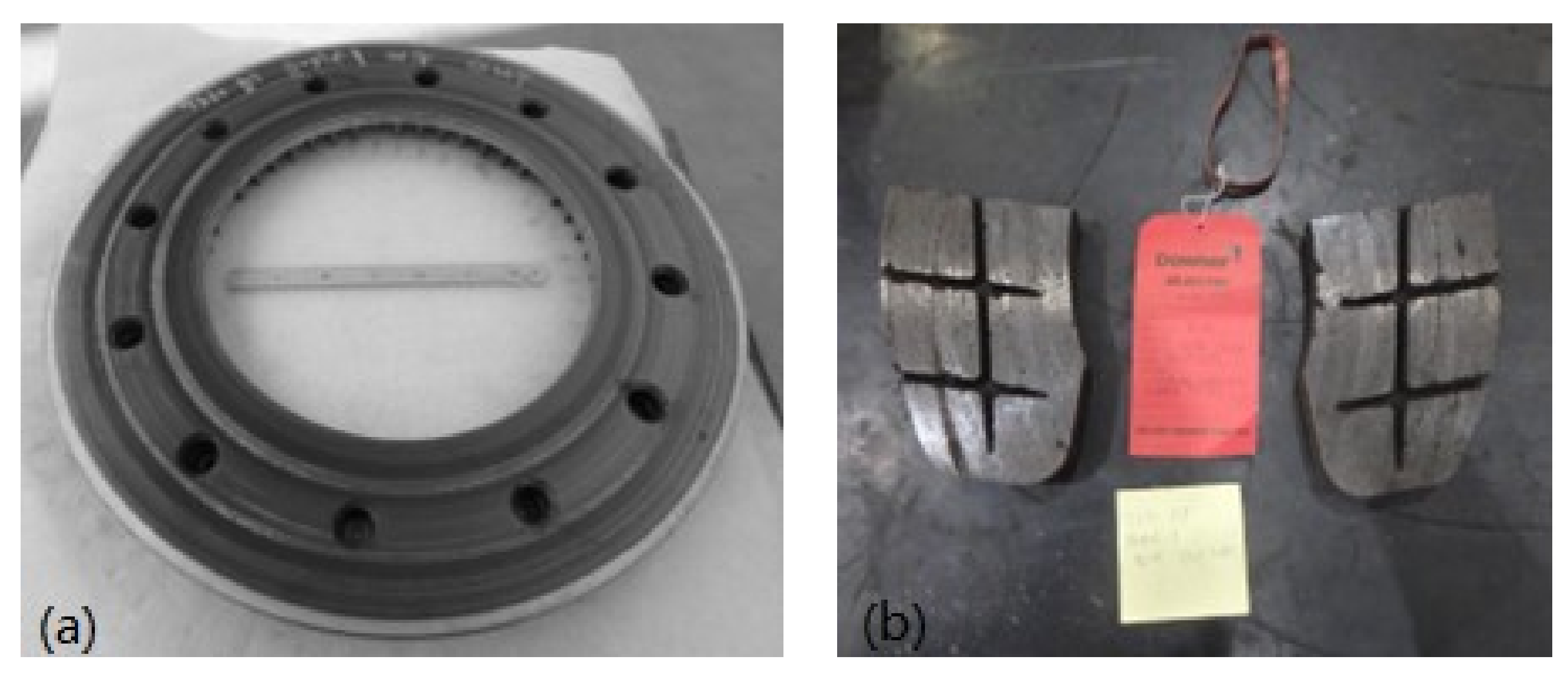
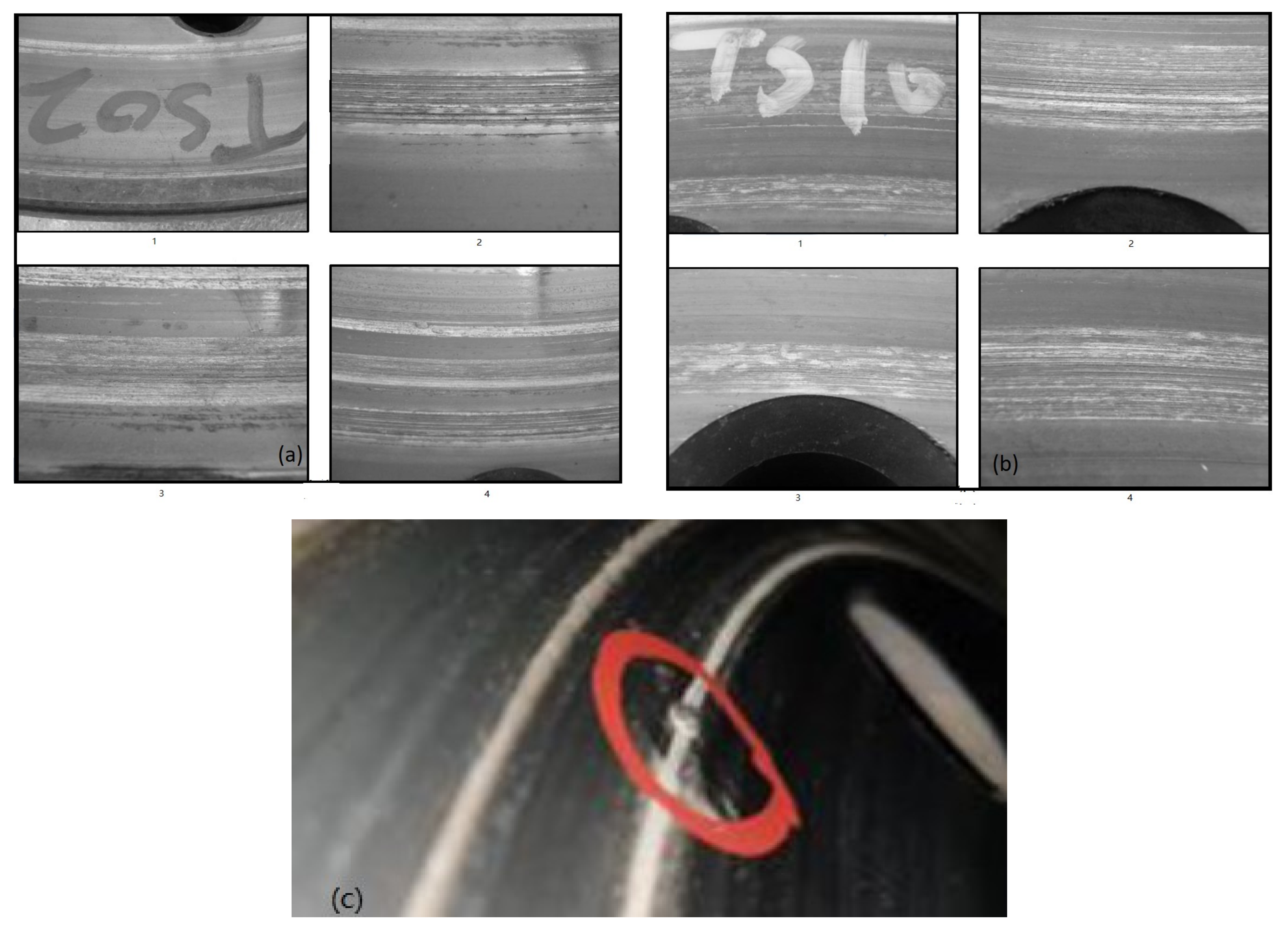
2.1. Visual Examination

These two sets of brake discs and brake pads (shown in below Figure 1 and Figure 2 were examined visually and with the aid of a high-powered binocular microscope.
As shown in Figure 1a and Figure 2a, both brake discs’ braking surfaces had abrasive wear interspersed with rings of adhesive wear. With the aid of a high-powered binocular microscope, it is observed that both sample’s regions of adhesive wear exhibited galling and smearing (as shown in Figure 3a,b). Both brake discs show abrasive wear in the friction rings. The scoring areas that are affected by abrasive wear are more obvious on TS02. The scoring reduced the effective contact area between the brake disc and brake pad and could potentially affect the available coefficient of friction of the brake system.
On the surface of brake disc 1, metallic protrusions were also observed. These protrusions are also referred to as welding pearls and can be caused by high localized temperature [6]. Welding pearls are raised areas of collected material that have fused onto a welding ring (See Figure 3c) [18].

2.2. Scanning Electron Microscopy

Samples were swabbed from the braking surfaces of the discs and submitted for examination by scanning electron microscopy (SEM). The scanning electron microscope employed was equipped with an energy dispersive spectroscopy (EDS) system (SEM, Carl Zeiss, Munich, Germany). The following results were obtained (refer to Figure 4).
SEM images of the subject swab samples from two brake discs are shown in Figure 4a–d respectively. The SEM images show the morphology of the particles and the particle distribution in the samples. The major constituents of particles on the swab from both samples were carbon, oxygen, iron, calcium, silicon, and aluminium. The components were not obviously different.

2.3. Positive Material Identification (PMI)

The testing was performed on Disc 1 and Disc 2 with Olympus Innov-X Delta, DP2000CC (S/No.: 510523) for Positive Material Identification. The results are presented in Table 3.
The principle of PMI testing of metals is based on X-ray fluorescence from the material under test being analyzed to determine the chemical elements present and their contents. X-ray fluorescence can be used to detect elements within several microns of a sample surface. Disc 2 (TS10) exhibited a significant difference in composition between the braked surface and the back surface (in Table 1). The silicon content at the braked surface was higher.

2.4. Surface Roughness Measurement

The brake discs were examined using a Mitutoyo Surftest SJ-210 surface roughness tester (Surftest, Mitutoyo, Kawasaki, Japan). The following results were obtained (refer Table 4). The measurements were performed at several predefined distances from the center of the brake disc. The average surface roughness (Ra) of the subject zones of Disc 1 was 1.74 μm. The average surface roughness (Ra) of the subject zones of Disc 2 was. 1.77 μm. No obvious difference was observed between the two disc samples. The surface roughness did not contribute to the reduced performance of the brake system.
The differences in the surface roughness between the two disc samples are not obvious.

2.5. Coefficient of Friction

The testing was performed on Disc 1 and Disc 2 using the equipment Instron 5982 (Instron, Norwood, MA, USA), 100 kN based on procedure ASTM G115-10(2018) D2394. The subject brake discs were examined using a horizontal flat to flat test such as that shown in ASTM G115 “Standard Guide for Measuring and Reporting Friction Coefficients” D2394. Brake pad blocks were used as the sliding flat. Test results show that the grand average coefficient of friction of the braking surface of Disc 1 (TS02) tested with Brake Pad TS02 was 0.26 (see Figure 5a). The grand average coefficient of friction of the braking surface of Disc 2 tested with Brake Pad TS10 was 0.22 (see Figure 5b).

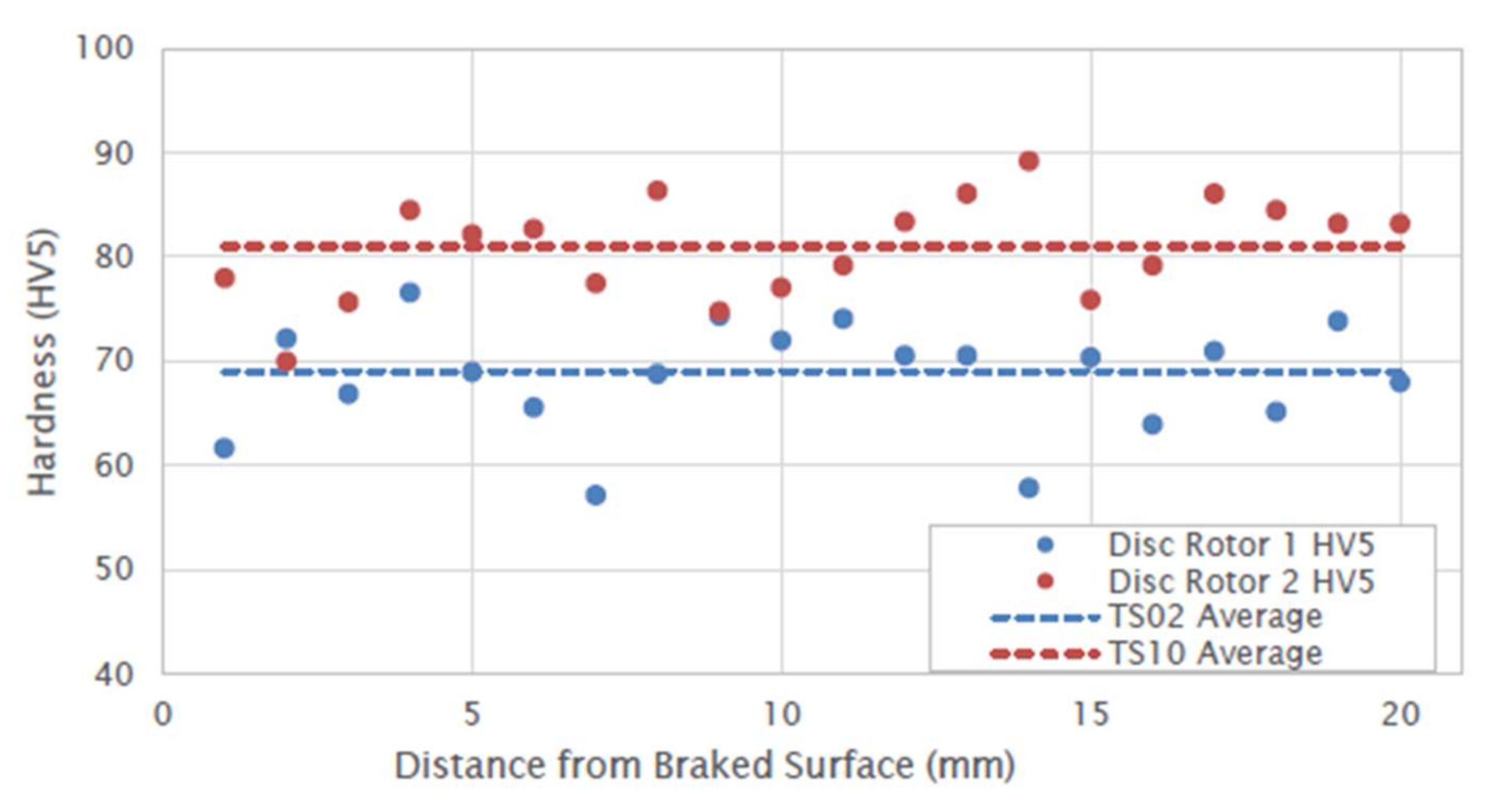
2.6. Hardness Testing

The subject brake discs were sectioned and metallographically prepared for Brinell hardness testing. All hardness testing was carried out in accordance with the requirements of AS 1816.1-2007 “Metallic materials—Brinell hardness test—Test method (ISO 6506-1:2005, MOD)” using a load of 500 kg and a 10 mm diameter ball. The following results were recorded (See Table 5).
The cross sections removed from Disc 1 and Disc 2 for metallography were prepared for hardness testing. All hardness testing was carried out in accordance with the requirements of AS 1817.1-2003 “Metallic materials—Vickers hardness test” using a load of 5 kg. A through-thickness hardness traverse at 1 mm spacing was conducted and the following results were recorded (see Figure 6).
Substantial scatter was observed in the test results for both disc material cross sections. The cast structure and the distribution of silicon carbide throughout the disc materials were considered to be contributing factors to the scatter observed. The core hardness of the Disc 1 material was 68.5 HV. The core hardness of the Disc 2 material was 80.9 HV. The core hardness of the Disc 1 material was lower than that of the Disc 2 material. In principle, with the same brake pads, Disc 1 would suffer from poorer wear resistance than Disc 2 [19,20,21,22,23,24,25].

2.7. Metallographic/Micrographic Examination

Sections were removed from Disc 1 and Disc 2 and metallographically prepared for microstructural evaluation. The following features were observed.
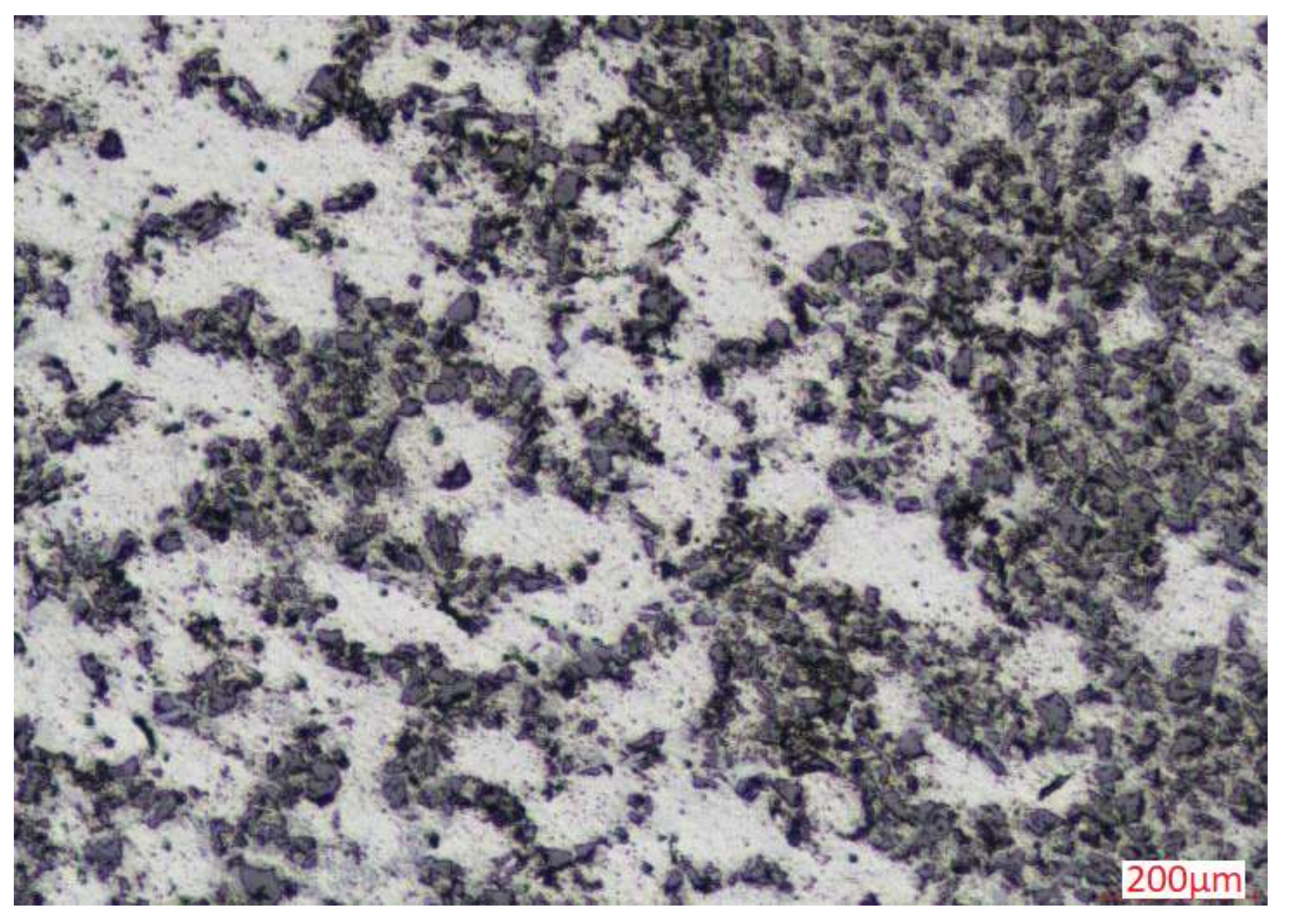
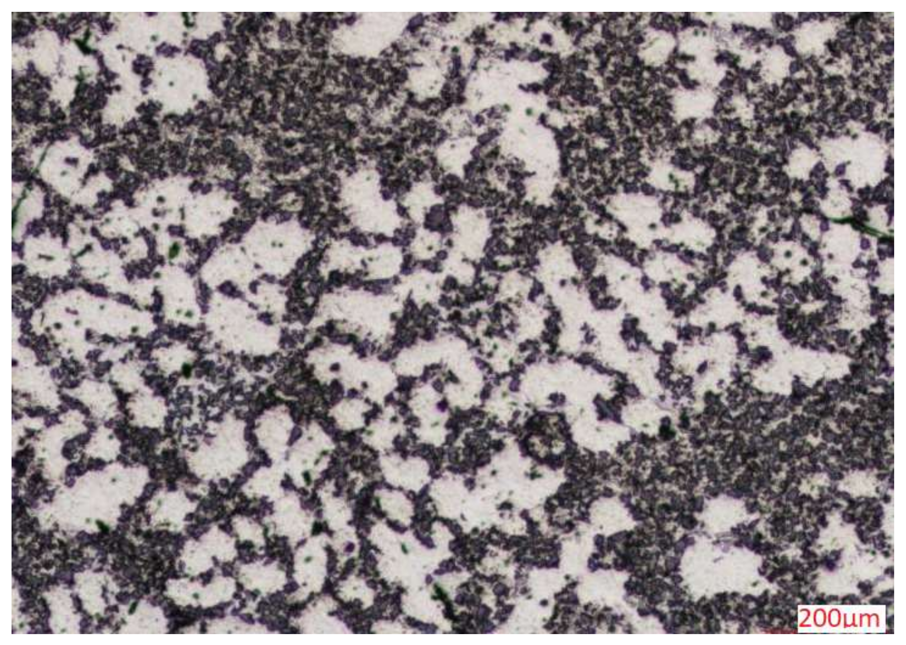
  • For Disc 1: At low magnification, the section of Disc 1 (TS02) removed for metallographic examination exhibited a good distribution of fine silicon carbides throughout (see Figure 7). The unetched core microstructure consisted of a refined structure of alpha aluminium (light phase) with primary silicon particles (mid grey), eutectic silicon (mid grey,) and silicon carbide particulate (dark grey). The microstructure was relatively fine-grained and uniform throughout the subject section. No unusual or deleterious features were observed in the subject section. In regions of abrasive wear, the microstructure of subject Brake Disk 1 (TS02) exhibited a localized silicon rich layer at the braked surface. At high magnification, the localized silicon-rich layer at the braked surface was estimated metallographically to be approximately 5–10 μm thickness. In regions of adhesive wear, the localized silicon-rich layer was absent at the braking surface.
  • For Disc 2: At low magnification, the section of Disc 2 (TS10) removed for metallographic examination exhibited a good distribution of fine silicon carbides throughout (see Figure 8). The unetched core microstructure consisted of a refined structure of alpha aluminium (light phase) with primary silicon particles (mid grey), eutectic silicon (mid grey), and silicon carbide particulate (dark grey). The microstructure was relatively fine-grained and uniform throughout the subject section. No unusual or deleterious features were observed in the subject section. In regions of abrasive wear, the microstructure of subject Disc 2 (TS10) exhibited a localized silicon-rich layer at the braked surface of the discs. At high magnification, the localized silicon rich layer at the braked surface was estimated metallographically to be approximately 15–20 μm in thickness. In regions of adhesive wear, the localized silicon-rich layer was intermittent and varied in thickness at the braking surface.
From the reinforcement point of view, the mechanical and wear properties of the localized silicon-rich layer are improved. The wear rate is lower due to the presence of hard SiC particles in composites. SiC particles are hard and hence they can resist abrasion. In addition, SiC particles in the composite layer also reduce contact between the counter surface and soft substrate and share some load. Reduced contact between counter surface and soft substrate and load sharing leads to reduced wear rate [26].

3. Discussion

The external factors that may affect the brake system performance have also been studied. For rail conditions, all the tests were completed on dry, clean rail heads. All test results with wheel slip event detected will be excluded from the final results to ensure the wheel slip would not affect the calculation of brake distance. For brake system conditions: the tested train’s brake pads are being stored in a dry environment protected from weather and direct sunlight prior to installation. Pads that are installed on trains are often exposed to weather during testing and when vehicles are stabled outside. The integrity of the brake pad material is not adversely affected by exposure to environmental conditions. All the brake pads on the tested trains were installed for less than 2 years. The service lifetime of brake pad material is limited to a maximum of eight years. For track gradient and curvature: all stops during the brake testing were carried out on straight sections of track to eliminate any effect that track curvature may have on the measured stopping distance. For system pressure tightness: The brake system tested is the pneumatic brake system, and the tightness of the pneumatic brake system has been checked with no problems.
It was observed in disc sample 1 from TS02 the affected trains had a reduced contacting surface between the brake pad and brake disc. The reduced contacting surface was a consequence of the welding pearls on the brake disc surface. The welding pearls on the brake disc will cause abrasive wear on the brake pad hence reducing the effective contacting surface between the brake pad and brake disc and eventually reducing the brake performance. The studies of the brake pads and brake discs in the laboratory also found the surface hardness of Brake Disc 1 from TS02 the affected train is lower than that of Brake Disc 2 from TS10. For aluminium-based brake discs, a thick transfer film [27] will be formed on the aluminium brake disc from the brake pad. This transfer film will be built during the running in process [28]. The transfer film acts as the contacting surface to rub against brake pad, enhancing the brake performance and boost the service life of an aluminium brake disc [14,29]. The protrusions on the disc surface prevent the formation of the transfer film, causing the abrasive wear on brake pads and thus leading to the reduced contact surface area between the brake pad and brake disc. This eventually led to a reduced performance of the brake system due to the reduced effective coefficient of friction of the brake system. The transfer film is mainly formed with the harder particles liberated from the brake pad, the poor formation of the transfer film on Brake Disc 1 from TS02 also shows a smaller surface hardness level than the Brake Disc 2 from TS10.

4. Conclusions

This study implemented the method of exclusion to analyze reasons that lead to the reduction in brake performance of High-Capacity Metro Trains. The factors have been listed and analyzed experimentally. It was found that reduced transfer film thickness, reduced hardness, and the formation of metal extrusion-like welding pearls had contributed to the reduced brake system performance. The metal protrusions on all the brake discs on TS02 were removed from the brake disc surface in the wheel lathe workshop, where the wheel lathe is used to machine wheel profiles for rolling stock brake discs [30,31]. New brake pads were installed on TS02. TS02 has then undergone a brake bedding process based on the manufacturer’s guidelines. The same dynamic brake tests were performed. After skimming the brake disc, a significant number of braking tests were completed at all speeds (up to 143 kph) in all load conditions. Passing results were achieved at all speeds and weight ranges. The metallic protrusion on the brake disc surface has caused the abrasive wear on the brake pad, reduced friction surface, poor formation of transfer film, and eventually caused a reduced coefficient of friction and performance. Further studies are still required to understand the reason for the formation of metallic protrusions.

Author Contributions

Conceptualization, C.Y., H.Y. and Q.C.; methodology, Y.L.; validation, C.Y., H.Y. and Q.C.; formal analysis, C.Y.; investigation, Q.C.; resources, H.Y.; data curation, Y.L.; writing—original draft preparation, C.Y.; writing—review and editing, N.Z.; visualization, N.Z.; supervision, Y.L.; project administration, H.Y.; funding acquisition, H.Y. All authors have read and agreed to the published version of the manuscript.

Funding

This research received no external funding.

Institutional Review Board Statement

Not applicable.

Informed Consent Statement

Not applicable.

Data Availability Statement

Not applicable.

Conflicts of Interest

The authors declare no conflict of interest.

References

  1. Valigi, M.C.; Logozzo, S.; Affatato, S. New challenges in tribology: Wear assessment using 3D optical scanners. Materials 2017, 10, 548. [Google Scholar] [CrossRef] [PubMed]
  2. Hawryluk, M.; Ziemba, J.; Dworzak, Ł. Development of a method for tool wear analysis using 3D scanning. Metrol. Meas. Syst. 2017, 24, 739–757. [Google Scholar] [CrossRef] [Green Version]
  3. Joel, J.; Xavior, M.A. Aluminium alloy composites and its machinability studies: A review. Mater. Today Proc. 2018, 5, 13556–13562. [Google Scholar] [CrossRef]
  4. Sedlák, J.; Hrušecká, D.; Chromjaková, F.; Majerík, J.; Barényi, I. Analysis of the wear on machined groove profiles using reverse engineering technology. Manuf. Technol. 2021, 21, 529–538. [Google Scholar] [CrossRef]
  5. Valigi, M.; Logozzo, S.; Butini, E.; Meli, E.; Marini, L.; Rindi, A. Experimental evaluation of tramway track wear by means of 3D metrological optical scanners. Tribol.-Mater. Surf. Interfaces 2021, 15, 150–158. [Google Scholar] [CrossRef]
  6. Valigi, M.C.; Logozzo, S.; Meli, E.; Rindi, A. New instrumented trolleys and a procedure for automatic 3D optical inspection of railways. Sensors 2020, 20, 2927. [Google Scholar] [CrossRef]
  7. Velavan, K.; Palanikumar, K.; Natarajan, E.; Lim, W.H. Implications on the influence of mica on the mechanical properties of cast hybrid (Al + 10% B4C + Mica) metal matrix composite. J. Mater. Res. Technol. 2021, 10, 99–109. [Google Scholar] [CrossRef]
  8. Prakash, S.; Sasikumar, R.; Natarajan, E.; Suresha, B. Influence of feeding techniques in bottom tapping stir casting process for fabrication of alumina nano-filler-reinforced aluminium composites. Trans. Indian Inst. Met. 2020, 73, 1265–1272. [Google Scholar] [CrossRef]
  9. Swamy, P.K.; Mylaraiah, S.; Basheer, D. Evaluation of Microstructure, Hardness, and Tensile Properties: A Comparative Study of Stir Cast and Extruded Al7005/Glass-/Fly-Ash-Reinforced Hybrid MMCs. Adv. Mater. Sci. Eng. 2021, 2021, 8601484. [Google Scholar] [CrossRef]
  10. Yu, L.; Jiang, Y.L.; Lu, S.K.; Ru, H.Q.; Fang, M. FEM for brake discs of SiC 3D continuous ceramic reinforced 7075 aluminum alloy for CRH3 trains applying emergency braking. Appl. Mech. Mater. 2011, 120, 51–55. [Google Scholar] [CrossRef]
  11. Thilak, V.; Krishnaraj, R.; Sakthivel, M.; Kanthavel, K.; Marudachalam, M.; Palani, R. Transient thermal and structural analysis of the rotor disc of disc brake. Int. J. Sci. Eng. Res. 2011, 2, 2229–2551. [Google Scholar]
  12. Nieh, T.; Xia, K.; Langdon, T. Mechanical properties of discontinuous SiC reinforced aluminum composites at elevated temperatures. J. Eng. Mater. Technol. 1988, 110, 77–82. [Google Scholar] [CrossRef]
  13. Mazahery, A.; Shabani, M.O. Microstructural and abrasive wear properties of SiC reinforced aluminum-based composite produced by compocasting. Trans. Nonferrous Met. Soc. China 2013, 23, 1905–1914. [Google Scholar] [CrossRef]
  14. Natarajan, N.; Vijayarangan, S.; Rajendran, I. Wear behaviour of A356/25SiCp aluminium matrix composites sliding against automobile friction material. Wear 2006, 261, 812–822. [Google Scholar] [CrossRef]
  15. Manjunath, N. FME Transactions; Faculty of Mechanical Engineering, Belgrade University: Beograd, Serbia, 2021; Volume 49. [Google Scholar]
  16. Sethuram, D. Characterization of graphene reinforced Al-Sn nanocomposite produced by mechanical alloying and vacuum hot pressing. Mater. Today Proc. 2018, 5, 24505–24514. [Google Scholar] [CrossRef]
  17. Lakshmikanthan, J. Microstructure, mechanical and wear properties of the A357 composites reinforced with dual sized SiC particles. J. Alloys Compd. 2019, 786, 570–580. [Google Scholar] [CrossRef]
  18. Ahmad, F.; Lo, S.J.; Aslam, M.; Haziq, A. Tribology behaviour of alumina particles reinforced aluminium matrix composites and brake disc materials. Procedia Eng. 2013, 68, 674–680. [Google Scholar] [CrossRef] [Green Version]
  19. Lijesh, K.; Kumar, D.; Hirani, H. Effect of disc hardness on MR brake performance. Eng. Fail. Anal. 2017, 74, 228–238. [Google Scholar] [CrossRef]
  20. Boldyrev, D.; Dema, R.; Kalugina, O. The microstructure and hardness of casting a solid brake disc after late graphitizing modification. IOP Conf. Ser. Mater. Sci. Eng. 2020, 966, 012021. [Google Scholar] [CrossRef]
  21. Odusote, J.K.; Talabi, S.I.; Agodinrin, G. Effect of Heat Treatment on Hardness and Wear Resistance of a Failed Automobile Brake Disc. Acta Tech. Corviniensis-Bull. Eng. 2014, 7, 129–132. [Google Scholar]
  22. Awe, S.A. Premature failure of an automobile brake disc: Effect of nonmetallic inclusions. Eng. Fail. Anal. 2022, 137, 106263. [Google Scholar] [CrossRef]
  23. Babu, K.V.; Marichamy, S.; Ganesan, P.; Madan, D.; Uthayakumar, M.; Rajan, T. Processing of functionally graded aluminum composite brake disc and machining parameters optimization. Mater. Today Proc. 2020, 21, 563–567. [Google Scholar] [CrossRef]
  24. Iyengar, S.; Sethuram, D.; Shobha, R.; Koppad, P. Microstructure, microhardness, and tensile properties of hot-rolled Al6061/TiB2/CeO2 hybrid composites. J. South. Afr. Inst. Min. Metall. 2021, 121, 543–548. [Google Scholar] [CrossRef]
  25. Puneeth, N.; Satheesh, J.; Koti, V.; Koppad, P.G.; Akbarpour, M.; Naveen, G. Application of Taguchi’s method to study the effect of processing parameters of Al6082/B4C/Al2SiO5 hybrid composites on mechanical properties. Mater. Res. Express 2019, 6, 1065a1. [Google Scholar] [CrossRef]
  26. Lakshmikanthan, A.; Udayagiri, S.B.; Koppad, P.G.; Gupta, M.; Munishamaiah, K.; Bontha, S. The effect of heat treatment on the mechanical and tribological properties of dual size SiC reinforced A357 matrix composites. J. Mater. Res. Technol. 2020, 9, 6434–6452. [Google Scholar] [CrossRef]
  27. Alnaqi, A.A.; Kosarieh, S.; Barton, D.C.; Brooks, P.C.; Shrestha, S. Material characterisation of lightweight disc brake rotors. Proc. Inst. Mech. Eng. Part L J. Mater. Des. Appl. 2018, 232, 555–565. [Google Scholar] [CrossRef] [Green Version]
  28. Matějka, V.; Metinöz, I.; Wahlström, J.; Alemani, M.; Perricone, G. On the running-in of brake pads and discs for dyno bench tests. Tribol. Int. 2017, 115, 424–431. [Google Scholar] [CrossRef]
  29. Chen, Y.; Modi, O.; Mhay, A.; Chrysanthou, A.; O’sullivan, J. The effect of different metallic counterface materials and different surface treatments on the wear and friction of polyamide 66 and its composite in rolling–sliding contact. Wear 2003, 255, 714–721. [Google Scholar] [CrossRef] [Green Version]
  30. Andrade, A.R.; Stow, J. Assessing the efficiency of maintenance operators: A case study of turning railway wheelsets on an under-floor wheel lathe. Proc. Inst. Mech. Eng. Part O J. Risk Reliab. 2017, 231, 155–163. [Google Scholar] [CrossRef]
  31. Lehrich, K.; WąsiK, M.; KosMoL, J. Identifying the causes of deterioration in the surface finish of a workpiece machined on a rail wheel lathe. Eksploat. Niezawodn. 2018, 20, 352–358. [Google Scholar] [CrossRef]
Figure 1. (a) General view of Brake Disc 1 from the affected trainset. (b) General view of Brake Pad 1 from the affected trainset.
Coatings 12 00894 g001
Figure 2. (a) General view of Brake Disc 2 from an unaffected trainset. (b) General view of Brake Pad 2 from an unaffected trainset.
Coatings 12 00894 g002
Figure 3. (a) Detailed views of the braking surface of Disc 1 from the affected trainset, (b) Detail views of the braking surface of Disc 2 from an unaffected trainset. (c) Example of a welding pearl.
Coatings 12 00894 g003
Figure 4. (a) SEM images showing morphology of Swab Sample from TS02, SE image, (b) SEM images showing morphology of Swab Sample from TS02, BSE image. (c) SEM images showing morphology of Swab from TS10, SE image. (d) SEM images showing morphology of Swab from TS10, BSE image.
Coatings 12 00894 g004
Figure 5. (a) TS02 disc test outcome, (b) TS10 disc test outcome.
Coatings 12 00894 g005
Figure 6. Through-thickness hardness traverse chart.
Coatings 12 00894 g006
Figure 7. Photomicrograph of the core microstructure of Disc 1 (TS02).
Coatings 12 00894 g007
Figure 8. Photomicrograph of the core microstructure of Disc 2 (TS10).
Coatings 12 00894 g008
Table 1. Brake pad set usage of the tested train.
-Pad APad BPad C
Date Installed-08 September 202021 November 2020
Date Testing Initiated23 October 201915 September 202025 November 2020
Odometer at Removal (km)~18,000~24,000~26,124
Energy Dissipated per Disc/Wheel [MJ] (friction only braking)3449257.31124.50
Total No. of Stops1536146107
Table 2. Sample details for examination.
IdentificationTrainsetLocationTime Taken
Brake Disc 1TS02TC2 W1 Out8 April 2021
Brake Pad 1TS02TC2 W1 Out8 April 2021
Brake Disc 2TS10DT W4 Out8 April 2021
Brake Pad 2TS10DT W4 Out8 April 2021
Table 3. PMI test results. Note that the Innov-X Delta DP2000CC analyses for elements with atomic number greater than 12 therefore the carbon and nitrogen content could not be determined.
IDAl
wt%
Si
wt%
Fe
wt%
Mg
wt%
Brake Disc 1 (Brake Surface)62.735.80.830.46
Brake Disc 1 (Back Surface)69.030.70.300
Brake Disc 2 (Brake Surface)37.059.42.190.64
Brake Disc 2 (Back Surface)69.130.10.150.53
Table 4. Surface roughness measurements.
Distance from Disc ID (mm)Disc 1
Braking Surface (Ra-μm)
Disc 2
Braking Surface (Ra-μm)
151.7110.246
305.5811.589
405.7176.066
500.3860.522
650.4410.971
800.3251.374
903.5744.690
1000.4470.437
1150.2652.048
1250.2600.388
1300.4421.176
Table 5. Bracket Hardness Test Results.
IdentificationBrinell Hardness Results (HBW 10/500)Average HBW
Disc 1 Surface62.9, 63.3, 63.863.3
Disc 2 Surface69.1, 67.3, 66.867.7
Publisher’s Note: MDPI stays neutral with regard to jurisdictional claims in published maps and institutional affiliations.

