Article

Bubble-Patterned Films by Inkjet Printing and Gas Foaming

by
Fausta Loffredo
1,†,
Fulvia Villani
1,*,†,
David Choy Buentello
2,3,
Grissel Trujillo-de Santiago
2,4,
Mario Moisés Alvarez
2,3,*,
Riccardo Miscioscia
1 and
Ernesto Di Maio
5,*
1
Portici Research Centre, Italian National Agency for New Technologies, Energy and Sustainable Economic Development (ENEA), 80055 Portici, Italy
2
Centro de Biotecnología-FEMSA, Tecnológico de Monterrey, Monterrey 64849, Mexico
3
Departamento de Bioingeniería, Escuela de Ingeniería y Ciencias, Tecnologico de Monterrey, Monterrey 64849, Mexico
4
Departamento de Ingeniería Mecatrónica y Eléctrica, Tecnologico de Monterrey, Monterrey 64849, Mexico
5
Dipartimento di Ingegneria Chimica, dei Materialie della Produzione Industriale, University of Naples Federico II, 80125 Naples, Italy
*
Authors to whom correspondence should be addressed.
These authors contributed equally to this work.
Coatings 2022, 12(6), 806; https://doi.org/10.3390/coatings12060806
Submission received: 5 May 2022 / Revised: 2 June 2022 / Accepted: 6 June 2022 / Published: 9 June 2022

Abstract

:
The micropatterning of thin films represents a challenging task, even for additive manufacturing techniques. In this work, we introduce the use of inkjet-printing technology coupled with a gas-foaming process, to produce patterned porosities on polymeric thin films, to develop a bubble-writing method. Inkjet printing of an aqueous solution of poly (vinyl alcohol) (PVA), a well-known gas-barrier polymer, allows the selective coating of a thin poly (lactic acid) (PLA) film, which is, successively, exposed to a gas-foaming process. The foaming of the thin PLA film is effective, only when PVA is printed on top, since the PVA barrier hinders the premature loss of the gas, thus allowing the formation of cavities (bubbles) in the covered areas; then, removing the PVA coating by water washing forms a bubble pattern. As a proof of concept, the surface-morphology features of the patterned porous PLA films have been proven effective at driving endothelial cell growth. A new technological platform is, hence, introduced in the field of tissue engineering and, in general, in fields involving thin films, where a patterned porous structure may add value.

Graphical Abstract

1. Introduction

The possibility to control the thin film topology is key in a large number of applications, such as biomedicine, health, engineering, and food.
In the biomedical sector, the patterning of surfaces with specific topology is used to study cell attachment and growth on surfaces and to control the organization of cell cultures.
The modification of the surface topology of biomaterials is widely employed, successfully, in tissue engineering and regeneration [1,2,3,4,5,6,7,8,9,10,11,12]. Surface patterning is, also, used to engineer diagnosis platforms. For instance, smart coatings can impart selective features to the surface of materials, to promote specific interactions with cells [13,14,15,16].
In general, as well as supporting the cell, the substrate can be used as a guide for adhesion, proliferation, morphology, and spreading, by providing physical and chemical signals [17,18]. Indeed, substrate topography (physical shape and size, roughness, wettability, porosity, surface energy, etc.) can affect the cellular functions differently, depending on both the cell type and the chemical properties of the substrate material as well as the substrate stiffness and the geometry of a potential regular pattern array, manufactured on top [19,20,21,22].
Topographical approaches take the advantages of the tools coming from the semiconductor industry and additive manufacturing, to fabricate well-defined surface features. The most common are based on soft lithography [7,20], laser-direct cell writing [7,20,23,24], photolithographic techniques [7,20], coatings of nanoparticles [11], 3D printing [12,25], 3D bioprinting [26], microcontact printing [7,13,14], and melt electro-writing [27].
In recent years, inkjet printing (IJP) has attracted attention as a flexible, low-cost technology to directly pattern solution-processable materials, at low temperature and without vacuum [28,29]. It consists of mask- and contact-free direct deposition and patterning, of sub-nL volumes of functional inks, onto different types of substrates, flexible or not. As a digital technology, it permits to design and fabricate different patterns (also with complex geometry) through suitable graphic software [30]. Moreover, since deposition and patterning are obtained in one step in a non-contact way, this technique allows to minimize contamination as well as reduce the waste amount and the consumption of expensive inks, with respect to other traditional deposition methods [28,29].
In general, IJP can be used both to deposit functional layers onto the substrate and to modify the properties of the substrate, by inducing micro-structuration [31,32,33,34], surface energy patterns [35,36,37], and differentiated adhesion forces [37,38]. The possibility of providing new functionalities to a specific substrate and mostly flexible substrates opened the way for new applications of inkjet printing technology in different research fields, such as optics [28,31,39], electronics [29,36,40], and biomedicine [37,38,41,42].
In order to produce specific patterns in thin polymeric films, IJP can be used alone or in hybrid combination with other traditional methods.
In this work, we use IJP as a tool to produce a pattern of a sacrificial barrier polymeric coating onto a thin polymer film, successively submitted to a gas-foaming process. The aim of the current research is to investigate the feasibility of producing bubbles close to the substrate surface and distributed in areas having their geometry controlled by the desired patterns. The idea is to develop a bubble-writing method, by combining the patterning capability of IJP technology with the ability of the gas-foaming process to induce porosity in a polymeric substrate. By using inkjet printing as tool to pattern the surface of thin-film polymer substrates with a material able to prevent gas loss prior to gas foaming, it is possible to produce a pattern of areas with bubbles on the substrate. Following this root, the limits of gas forming for the production of patterns of bubbles (cavities) on the surface of thin films can be overcome. Indeed, two reasons have, so far, prevented the use of gas foaming for the production of thin films with a patterned presence of bubbles on their surface: (i) when dealing with thin films, the blowing agent is easily lost in the surroundings at pressure quench, before any bubble is allowed to form [43]; and (ii) in gas foaming, the bubble formation is stochastic, so it is quite hard to control their position [44].
After foaming, the additive inkjet-printed coating layer is dissolved, and the substrate with the patterned bubbles can be used in different applications.
In order to test an initial potential application for this new type of substrate, with a micropattern of areas containing bubbles, a two-step process was carried out on a biocompatible substrate, based on poly (lactic acid) (PLA), and tested as a system, to induce the selective cell growth. PLA was chosen because it is an environmentally friendly polymer, being synthesized from renewable resources, such as starch, and has several interesting properties, among them biocompatibility and biodegradability, which make it versatile in different applications (food, packaging, biomedical devices, drug delivery system, optoelectronics) [8,9,10,45,46,47,48]. Here PLA was selected for both its biocompatibility properties and, also, considering its wide availability as a commercial product, in the form of thin and uniform films. The material used as barrier polymer to induce bubbles in the PLA, during gas foaming, is poly (vinyl alcohol) (PVA), a low-cost polymer known for its efficacy as a barrier to CO2, due to the low diffusivity of this gas through it [49,50], water solubility, low toxicity and high biocompatibility [51].
The efficacy of the patterned cell growth achieved as an example of bioengineering application, by the double-step process presented here, demonstrates the functionality of the method itself. To the best of our knowledge, this is the first report where cell culture is performed on PLA films patterned with gas foaming The novel proposed method takes advantage of being a combination of two low-cost, low-temperature, non-contact, high-throughput industrial technologies, employed to produce a bubble-patterned substrate that induces a specific cell interaction without applying chemicals, thus avoiding possible contamination and cell alteration, with reduced process timing and phases as well as no additional multistep treatments [7,11,12,13,14] and scalability potential.

2. Materials and Methods

2.1. Materials and Ink Preparation

Poly (lactic acid) (PLA) films were purchased from Bleher Folientechnik GmbH (Ditzingen, Germany), with a thickness of 50 μm. Poly (vinyl alcohol) (PVA) powders of different average molecular weights (Mw) (in the range 67,000–130,000 g/mol) were purchased by Aldrich and tested to produce water-based inks.
A PVA ink with chemico-physical properties suitable for the inkjet-printing process was obtained, by dissolving PVA (Mw~67,000, 86.7–88.7 mol% hydrolysis, 10.0–11.6% of residual content of acetyl) in ultra-pure water, at a concentration of 20 mg/mL. The solution was stirred at 50 °C for 2 h and, then, filtered with a 0.45 µm PVDF (polyvinylidene difluoride) filter, to remove possible residual agglomerates.

2.2. Characterization of Inks and Substrates

The PVA inks were characterized by a viscosimeter (SV-10, A&D Europe Gmbh, Darmstadt, Germany), in order to determine their viscosity, and a contact angle instrument (OCA20, DataPhysics Instruments GmbH, Filderstadt, Germany) was used to evaluate their surface tension (ST). ST measurements were performed in a pendant drop configuration, and the result was the average value of 10 repeated measurements carried out on each sample.
The OCA20 system was employed, also, to measure the surface energy of PLA substrates. This was estimated by dispensing on the cleaned substrate drops of water, as polar solvent, and diiodomethane, as apolar solvent, and fitting the respective contact angle results by OWRK method (Owen, Wendt, Rabel and Kaelble method). Moreover, in this case the result was the average value of 10 repeated measurements carried out for each sample.

2.3. Inkjet-Printing Process and Printed-PVA-Layer Characterization

The IJP system used to deposit and pattern the PVA ink was a Dimatix Materials Printer (DMP2831, Fujifilm Dimatix, Santa Clara, CA, USA). This system is equipped with a cartridge printhead, with 10 pL nominal drop volume. The printhead has 16 nozzles, with a nozzle opening of about 21.5 µm diameter.
Before printing, PLA films, employed as substrates, were cleaned with ethanol and dried with nitrogen flow. The printing parameters were optimized, in order to manufacture different arrays of PVA lines with different geometries (width, thicknesses of lines, and gaps between contiguous lines). This was performed by fixing the drop space (distance between the centers of contiguous drops) equal to 15 µm and employing different nozzle numbers (from 1 up to 5 nozzles). The number of overlapped layers investigated for each line was changed from 1 to 4.
The morphology and thickness of the PVA layers onto PLA substrates were analyzed, by means of the optical microscope of a Dimatix camera and optical profilometer (Taylor-Hobson, model CCI HD4K, Leicester, UK).

2.4. Gas Foaming Process and PLA Substrate Characterization

For the production of foamed samples, a thermoregulated pressure vessel, having a volume of 0.3 L, (BC-1, High Pressure Equipment Co., Erie, PA, USA) was used. The pressure discharge system consisted of a discharge valve (15–71 NFB, High Pressure Equipment Co., Erie, PA, USA), an electromechanical actuator (15–72 NFB TSR8, High Pressure Equipment Co., Erie, PA, USA), and an electrovalve. The pressure history was registered by using a data-acquisition system (DAQ PCI6036E, National Instruments, Austin, TX, USA) and a pressure transducer (P943, Schaevitz–Measurement Specialties, Hampton, VA, USA). In a typical experiment, the samples (PLA film partially covered by a PVA layer with a defined pattern) were loaded into the vessel, pressurized with the blowing agent at 14.0 MPa and 70 °C for 2 h, and pressure quenched at 100 MPa/s. PLA films were recovered, by dissolving the PVA films in water at room temperature, and washed with water five times. To verify the film morphology by SEM, foamed films were coated with gold (208HR high-resolution sputter coater, Cressington Scientific Instruments, Watford, England) and imaged with a field-emission-gun-scanning electron microscope (FEG-SEM; Carl Zeiss AG, Oberkochen, Germany).

2.5. Cell-Culture Experiments

Cell-culture experiments were conducted on the surface of the micropatterned films. To that end, human BJ fibroblasts (CRL-2522), purchased from ATCC®, were used. Cells were first expanded in Dulbecco’s Modified Eagle Medium (DMEM) (Sigma-Aldrich, St. Louis, MO, USA), in T25 bottles at 37 °C, under an atmosphere enriched with 5% CO2. Cells were harvested at 70% confluency, after three days of culture. For the experiments reported here, cells from a third to sixth pass were used.
Before cell seeding, the films were sterilized by exposure to an ethylene-oxide atmosphere (5 h at 25 °C) and coated with fibronectin to favor cell attachment. Seeding was done by depositing a drop of cell suspension (1.5 × 10⁶ cells·mL−1) on the surface of the films. Films were incubated for 6 days, and the culture medium was changed every third day.
At day 6, the samples were stained using Alexa Fluor® 488 phalloidin/4′,6-diamidino-2-phenylin-dole (DAPI, ThermoFisher Scientific, Waltham, MA, USA) in accordance with the instructions of the vendor, for actin/cell nuclei observation. An Axio Observer.Z1 microscope (Zeiss, Jena, Germany) was used to capture bright-field and fluorescence images. ImageJ (NIH) was used to assess cell orientation, using image analysis. For this, imaginary lines were drawn from each nucleus to the most elongated extreme of the cell. Then, the orientation angle of the imaginary line was measured, with respect to the main axis of the printed arrays. Cell-orientation angles were grouped in six different groups (i.e., alignment bins), to calculate the angle distribution. The observed angle distribution was compared to a homogeneous distribution (i.e., the distribution where all alignment bins exhibited an equal frequency of 16.66%) using a Chi-squared statistical test in Prism 8.4.3 (GraphPad, San Diego, CA, USA). A two-sided confidence level of 95% was chosen, to determine statistical significance.

3. Results and Discussion

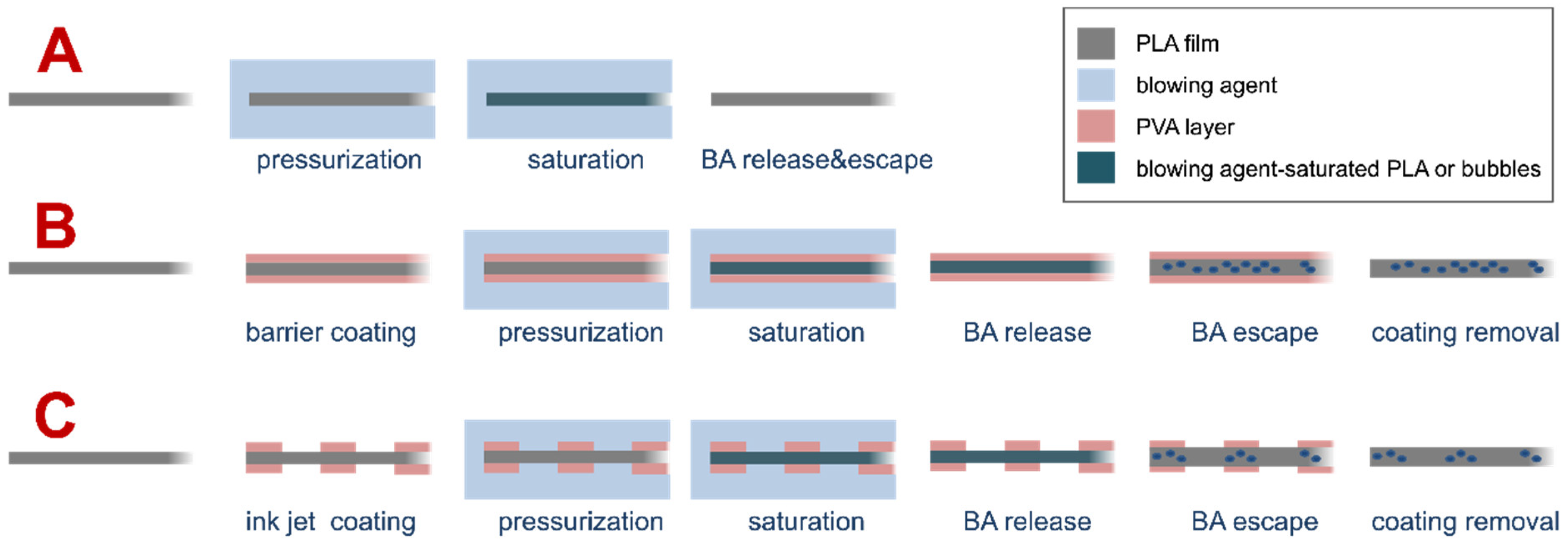
3.1. Description of the Investigated Process

We investigated the possibility of creating a controlled pattern of bubbles in polymer film, by a combination of two processes: an inkjet-printing deposition of a polymer coating and, in sequence, foaming of the patterned bilayer. The adopted approach is schematically displayed in Figure 1. As described in the introduction section, gas foaming of thin films is not feasible, due to gas escape prior to bubble nucleation (case A in Figure 1). The use of the PVA, a known barrier polymer for CO2, prevents gas escape and allows bubble formation in thin films (case B in Figure 1). By taking advantage of selectively inkjetting the PVA solution on the PLA film, it is possible to localize bubble formation (case C in Figure 1).

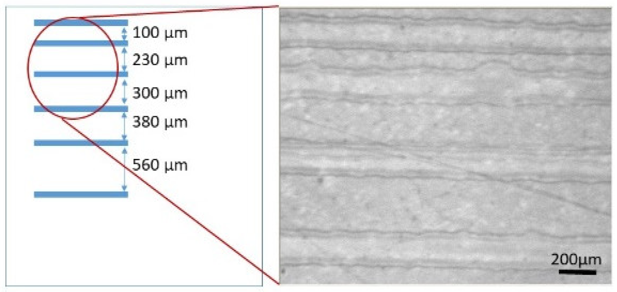
3.2. Patterning of PLA Substrate by Inkjet Printing Deposition of PVA Layer

In order to produce a PVA-based ink with chemico-physical properties suitable for the inkjet process, different formulations of PVA in aqueous solutions were prepared, by changing the concentration and weight-average molecular mass (Mw) of the polymer (in the range of 67,000–130,000 g/mol). Preliminary tests were carried out, to check the jettability of the formulated inks. According to the literature [52], we observed the formation of extended and stable ligaments, as polymer molecular weight and concentration increased. Instead, a stable jet was obtained by dissolving PVA of 67,000 g/mol in ultra-pure water, at a concentration of 20 mg/mL. The developed ink was characterized by a surface tension of 55 mN/m and a viscosity of 2 mPa·s, which are operating parameters suitable for the inkjet-printing process (Table 1). Moreover, the tension energy of the ink is only slightly higher than the surface energy of the substrate, so this is a good compromise between wettability and the spread of the drop hitting the substrate, in order to produce continuous lines.
Successively, we focused our study on investigating the right thickness of the PVA coating, suitable to block the gas escape out from the PLA substrate in the foaming process, making the bubble production effective. Indeed, to avoid blowing-agent loss in the expanding polymer, prior to foaming, a minimum thickness of the barrier polymer, PVA, is required. An estimate of the required thickness can be given, based on the bubble nucleation induction time, τn, provided by Taki et al. for the PLA/CO2 system [53,54], of the order of 10−1 s, and on the diffusivity of the CO2 in PVA, of the order of 10−12 m2·s−1 (as compared to 10−9 m2·s−1 for the PLA/CO2 system), giving a value of the order of 0.1 μm (≈D τn)1/2 [49].
Therefore, in the first part of the work, we fixed the geometry of the pattern (based on an array of lines with a gap of 300 μm between each other) to deposit onto the PLA substrate and tested the effect of multilayer deposition (overlapped layers) on the morphology and uniformity of the printed PVA lines. Both the optical microscopy and optical profilometer images of the line profile are displayed in Figure 2, where it is clearly noticeable that the accumulation of PVA at the edges of each line, due to the diffusion process of solute toward the line rim, as a consequence of the concentration gradient, increases, as the number of layers, also, increases. This effect is intrinsic to the multilayer inkjet process, where the deposition of the subsequent layer promotes a more pronounced coffee-ring effect. The measurements of the geometric parameters of the printed lines, by changing the overlapped layer number, are reported in Figure 3. As expected, the multilayer deposition induces an increment of the line thickness (Figure 3A). We put the attention on thickness at the inner flat region of the printed line, as it is a crucial element to block the escape of gas, during the subsequent foaming process. Additionally, the ratios between the thicknesses of the central flat section of the line and the two lateral ridges stay almost constant, around the value of 0.3, for all cases, suggesting that no partial dissolution of previously printed layers is induced by the successive layers, with respect to the single-printed-layer configuration. Hence, the multilayer printing process additively piles PVA equally along the line, increasing the peak and the inner-area thicknesses, proportionally. Concerning the width of each line, it slightly increases, inducing a decrease in the gap between consecutive lines (Figure 3B).
The results of Figure 3A demonstrate that a thickness of 0.1 μm, evaluated as the minimum value to make the foaming effective, was assured by all the investigated configurations. Anyway, the risk to produce pinholes in the single printed layer could be higher than for multilayers, which would induce an imperfectly uniform film. At the light of the obtained considerations, we evaluated that the lines printed with three overlapped layers represent an intermediate comfortable condition, to guarantee regular (even) lines with the reduced process steps (minimum printed layer number).
Consequently, in the second part of the work, the arrays of PLA lines with different geometry were printed on PLA. In detail, we fixed the drop space (DS = 15 µm), the number of overlapped layers (2 layers), and the width of lines (200 µm) as well as changed the gap between consecutive lines, as schemed in Figure 4—left. In Figure 4—right, the optical image of a few lines, as a part of the printed array, is displayed as an example, where different gaps between lines are clearly visible.

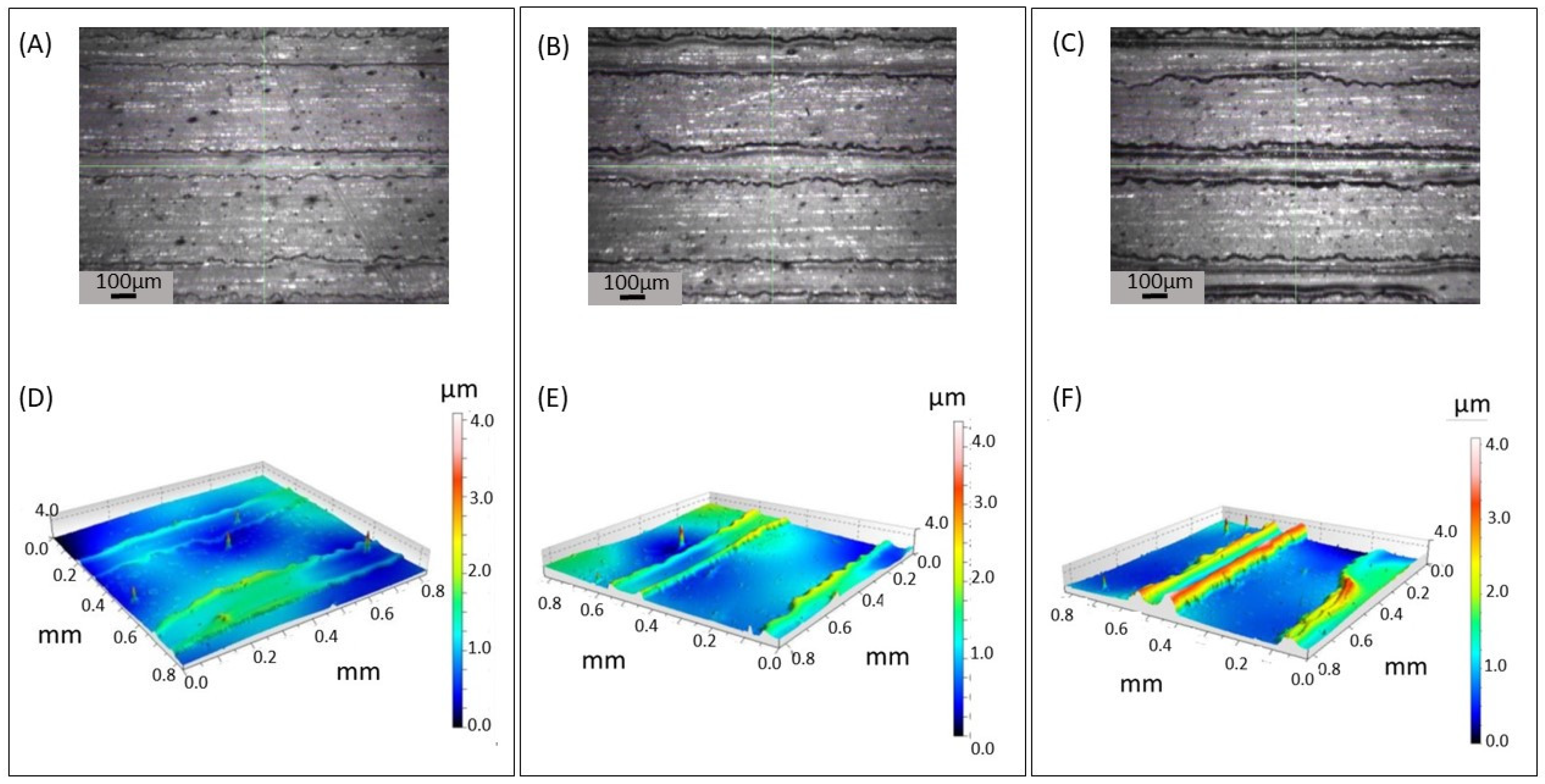
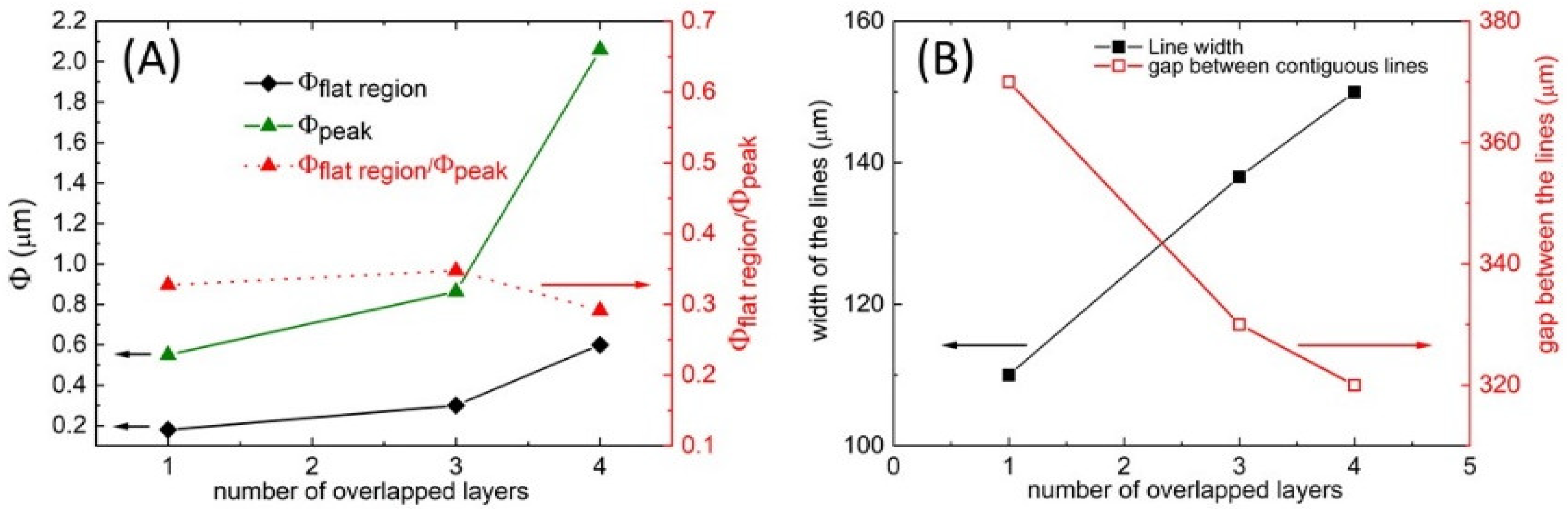
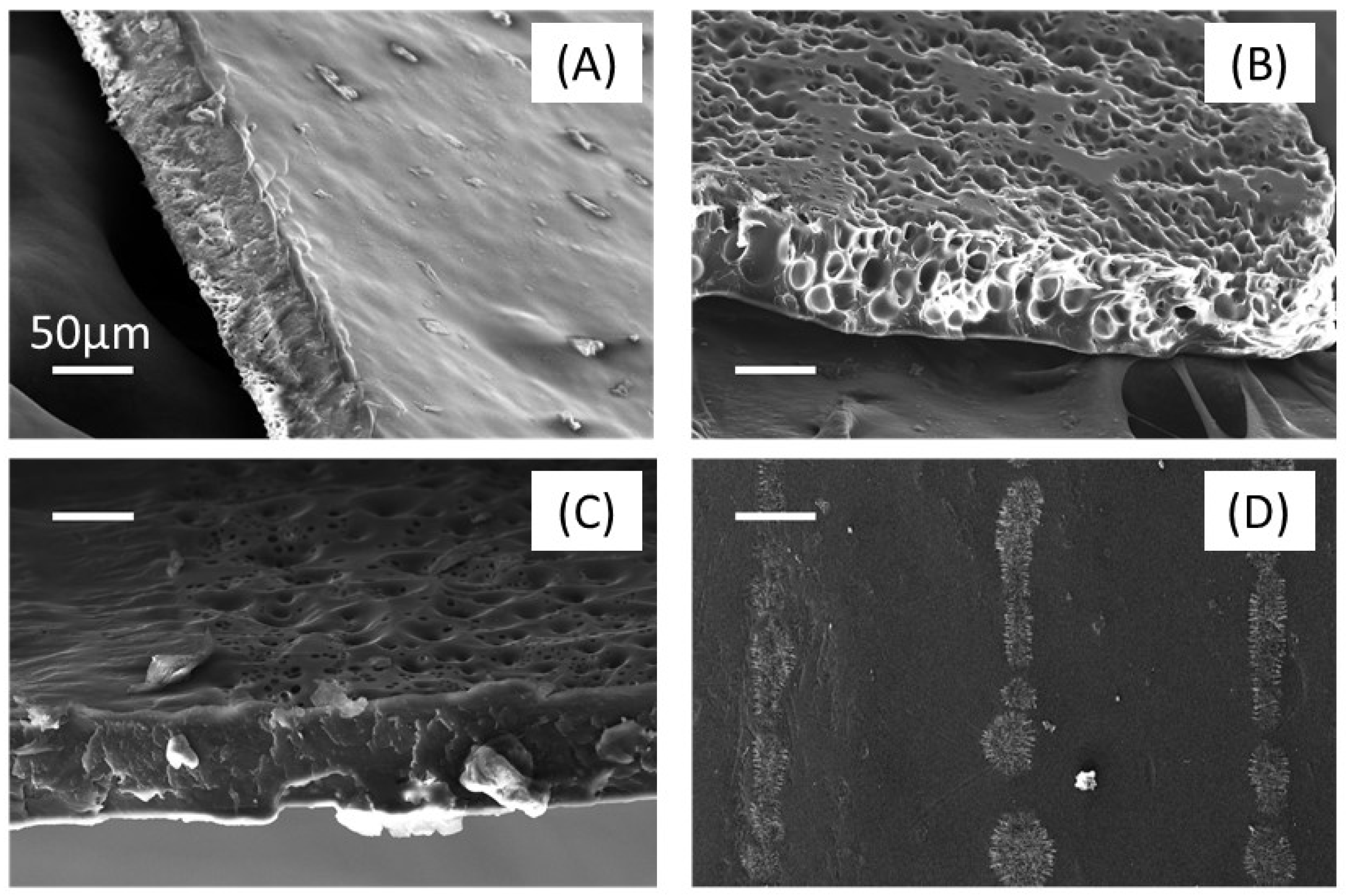
3.3. Gas Foaming of PLA Substrate Patterned with PVA Coating

Scanning-electron analysis revealed the efficacy of the barrier-layer approach on PLA films’ selective foaming. Figure 5 shows images of PLA films subjected to the inkjet and foaming process. Figure 5A displays the image of a PLA film sample, which was not covered by the barrier layer before foaming. In this case, foaming did not induce bubble formation, due to blowing-agent loss before bubble nucleation. Figure 5B shows the image of the PLA film and that it was preliminarily covered by the PVA layer, uniformly on the whole surface, by solution casting: the presence of bubbles, due to foaming, is evident here, proving the efficacy of the PVA layer in preventing the blowing-agent loss and the resulting ability of the blowing agent to form bubbles. Figure 5C,D report images of films, where the PVA barrier layer was first inkjetted on selected areas of the PLA film, then the whole film was subjected to foaming, and, successively, the barrier layer was washed away by water rinsing. Images show a selective presence of the bubbles, both on the surface and in the film thickness, only where the barrier layer was deposited. Films with the patterned porosities were, then, utilized for cell-culture experiments, to assess the effect of the patterned morphology on cell-harvesting guidance.

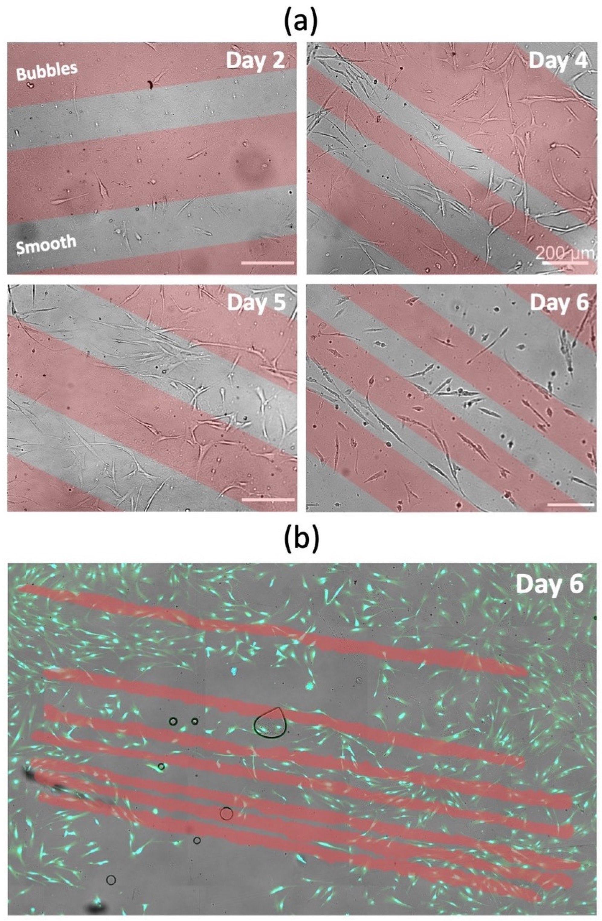
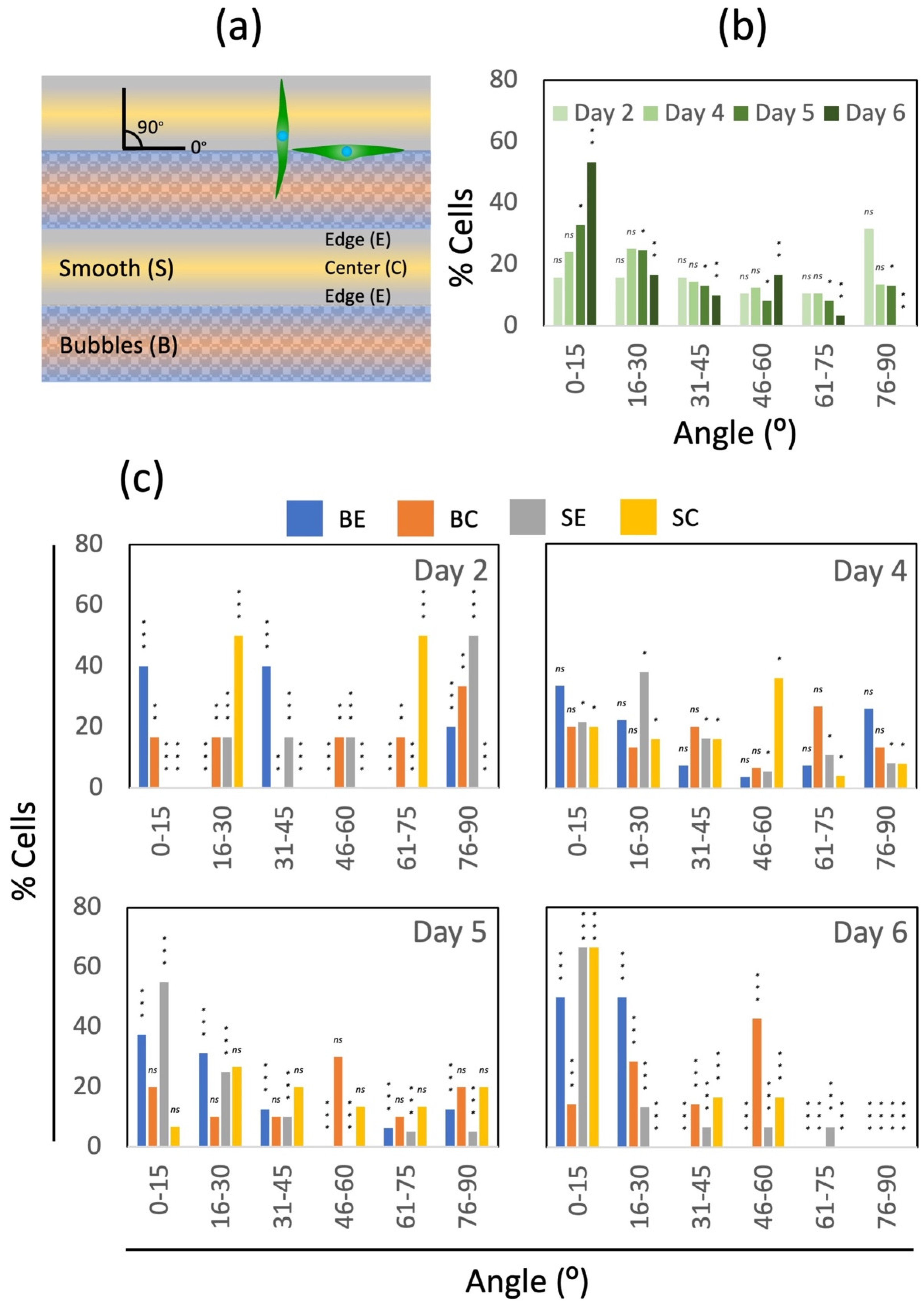
3.4. Cell-Culture Experiments

A vast body of experimental evidence demonstrates that cells are highly responsive to topological cues [55,56,57,58,59,60]. Surface-patterning technologies have been frequently explored to influence cell morphology. To assess the effect of our patterns in cellular organization, we cultured human fibroblasts on the PLA film, shown in Figure 4 (previously coated with fibronectin, to favor cell attachment), and monitored cell growth by optical microscopy for 6 days (Figure 6a). In general, more fibroblasts attached to the smooth surfaces than to the foamed areas. Furthermore, cells that grow at the frontiers between the smooth and bubble arrays aligned parallelly to the patterns (Figure 6b).
We, also, assessed cell orientation using image analysis. To this aim, we defined four different zones in the printed films: smooth-surface center (SC), smooth-surface edge (SE), bubbles-array center (BC), and bubbles-array edges (BE). We measured the cell orientation, with respect to the printed lines; cells parallelly orientated to the printed line exhibited an angle of 0°, while cells perpendicularly orientated exhibited an angle of 90° (Figure 7a). Our cell-culture experiments suggest that bubble patterning is effective in inducing cell orientation. Figure 7b presents the overall distribution of angles, exhibited by cells within lines. We observed a clear trend of cell alignment toward the printed arrays, over time. The frequency of low-number angles (0–15°) increases from day 2 to 6, while the frequency of high-number angles (76–90°) decreases (Figure 7c). Counterintuitively, cells did not preferentially attach on bubbled patterns, where the surface area was increased. Previous reports showed that adding roughness to PLA surfaces (pores, pits, islands, and nano-roughness) enhanced cell attachment [9,61,62]. In our case the analysis of micrographs suggests that foamed lines act as obstacles, which the cells avoid, and serve as a guide for alignment. This is consistent with observations from previous studies [63], which have found that sections of surfaces patterned with arrays of nano-craters repel the anchorage of cells and, therefore, may be used to induce specific predesigned cell patterns. The different behaviors observed, when comparing different processes applied to modify the biomaterial surfaces, are complex functions involving a multiplicity of interconnected parameters that control the processes themselves and, consequentially, the properties of the materials [8]. That makes the comparison among similar cell-substrate systems, from the literature, difficult [8]. In any case, by comparing with other strategies that were adopted to modify the surfaces promoting effective cell attachment and alignment [11,12], the technology presented here offers, among several advantages [7,11,12,13,14], a notable one: that the foamed product is only PLA (i.e., does not carry contaminants nor involve the use of other materials or fillers that could be cytotoxic).
Surfaces repellent to cells are, also, of interest in diagnosis applications. Potential future avenues of this work include the development of sensors for biomedical applications [13,14].

4. Conclusions

We introduced a combined technique, based on inkjet printing and polymer foaming, to form thin PLA films with a patterned porosity. Namely, inkjet printing of a PVA/water solution was adopted to form, onto the PLA films, stripes of PVA at water evaporation. Gas foaming with CO2 was, then, adopted on the PVA-pattern-covered PLA films, to induce selective foaming of the PLA. During the foaming operations, PVA, a barrier polymer toward CO2, prevented premature CO2 escape, from the thin film at pressure quench, and allowed selective foaming. Inkjet-parameters optimization allowed the formation of PVA stripes of shape and thickness suitable for the barrier role, as they were designed considering the gas foaming and diffusion-characteristic times. Different pattern morphologies, in terms of the macroscopic pattern as well as the microscopic pore architecture, were achieved. Porosity-patterned PLA films were tested as tissue-engineering substrates, to guide cell adhesion and harvesting. Cells oriented in the pattern direction after 6 days, proving the effectiveness of the method to produce 2D devices for tissue engineering. More generally, we showed that the coupled technique can represent a new technological platform in fields involving thin films, where a patterned porous structure may add value.

Author Contributions

Conceptualization, E.D.M., F.V., F.L., G.T.-d.S., D.C.B. and M.M.A.; validation, E.D.M., F.V., F.L., R.M., G.T.-d.S., D.C.B. and M.M.A.; investigation, E.D.M., F.V., F.L., R.M., G.T.-d.S., D.C.B. and M.M.A.; resources, E.D.M., F.V., F.L., R.M., G.T.-d.S., D.C.B. and M.M.A.; data curation, E.D.M., F.V., F.L., R.M., G.T.-d.S., D.C.B. and M.M.A.; writing–original draft preparation, F.L. and F.V.; writing–review and editing, E.D.M., F.V., F.L., R.M., G.T.-d.S., D.C.B. and M.M.A.; visualization, E.D.M., F.V., F.L., R.M., G.T.-d.S., D.C.B. and M.M.A.; supervision, E.D.M., F.V., F.L., R.M., G.T.-d.S., D.C.B. and M.M.A. All authors have read and agreed to the published version of the manuscript.

Funding

This research was partially funded by Consejo Nacional de Ciencia y Tecnología (CONACyT) in the form of a doctoral scholarship for D.C.B. G.T.-d.S. acknowledges the funding received from Consejo Nacional de Ciencia y Tecnología (CONACyT), and AMC-CONACyT-LOréal. M.M.A. acknowledges the institutional funding received from Tecnológico de Monterrey and funding provided by CONACyT.

Institutional Review Board Statement

Not applicable.

Informed Consent Statement

Not applicable.

Data Availability Statement

Data underlying the results presented in this paper are not publicly available at this time but may be obtained from the authors upon reasonable request.

Acknowledgments

The authors acknowledge the experimental contribution of Brenda Giselle Flores Garza.

Conflicts of Interest

The authors declare no conflict of interest.

References

  1. Hoffman-Kim, D.; Mitchel, J.A.; Bellamkonda, R.V. Topography, cell response, and nerve regeneration. Annu. Rev. Biomed. Eng. 2010, 12, 203–231. [Google Scholar] [CrossRef] [PubMed] [Green Version]
  2. Garland, S.P.; McKee, C.T.; Chang, Y.R.; Raghunathan, V.K.; Russell, P.; Murphy, C. A cell culture substrate with biologically relevant size-scale topography and compliance of the basement membrane. Langmuir 2014, 30, 2104–2108. [Google Scholar] [CrossRef] [PubMed]
  3. Mun, K.S.; Kumar, G.; Co, C.C.; Ho, C.C. Micropatterning different cell types with microarray amplification of natural directional persistence. Adv. Healthc. Mater. 2013, 2, 334–342. [Google Scholar] [CrossRef] [PubMed] [Green Version]
  4. Voskuhl, J.; Brinkmann, J.; Jonkheijm, P. Advances in contact printing technologies of carbohydrate, peptide and protein arrays. Curr. Opin. Chem. Biol. 2014, 18, 1–7. [Google Scholar] [CrossRef]
  5. Jeon, H.; Simon, C.G., Jr.; Kim, G. A mini-review: Cell response to microscale, nanoscale, and hierarchical patterning of surface structure. J. Biomed. Mater. Res. B Appl. Biomater. 2014, 102, 1580–1594. [Google Scholar] [CrossRef]
  6. Angelova, L.; Daskalova, A.; Mincheva, R.; Carette, X.; Trifonov, A.; Filipov, E.; Aceti, D.; Buchvarov, I. Ultra-fast laser modification of poly-lactic acid (PLA)—Towards enhanced biocompatibility. J. Phys. Conf. Ser. 2022, 2240, 012042. [Google Scholar] [CrossRef]
  7. Li, P.; Dou, X.; Schönherr, H. Micropatterning and nanopatterning with polymeric materials for advanced biointerface-controlled systems. Polym. Int. 2019, 68, 1015–1032. [Google Scholar] [CrossRef]
  8. Tilkin, R.G.; Régibeau, N.; Lambert, S.D.; Grandfils, C. Correlation between Surface Properties of Polystyrene and Polylactide Materials and Fibroblast and Osteoblast Cell Line Behavior: A Critical Overview of the Literature. Biomacromolecules 2020, 21, 1995–2013. [Google Scholar] [CrossRef]
  9. Bu, Y.; Ma, J.; Bei, J.; Wang, S. Surface Modification of Aliphatic Polyester to Enhance Biocompatibility. Front. Bioeng. Biotechnol. 2019, 7, 98. [Google Scholar] [CrossRef]
  10. Lednev, I.; Salomatina, E.; Ilyina, S.; Zaitsev, S.; Kovylin, R.; Smirnova, L. Development of Biodegradable Polymer Blends Based on Chitosan and Polylactide and Study of Their Properties. Materials 2021, 14, 4900. [Google Scholar] [CrossRef]
  11. Wu, F.; Zheng, J.; Li, Z.; Liu, M. Halloysite nanotubes coated 3D printed PLA pattern for guiding human mesenchymal stem cells (hMSCs) orientation. Chem. Eng. J. 2019, 359, 672–683. [Google Scholar] [CrossRef]
  12. Gasparotto, M.; Bellet, P.; Scapin, G.; Busetto, R.; Rampazzo, C.; Vitiello, L.; Shah, D.I.; Filippini, F. 3D Printed Graphene-PLA Scaffolds Promote Cell Alignment and Differentiation. Int. J. Mol. Sci. 2022, 23, 1736. [Google Scholar] [CrossRef] [PubMed]
  13. Kim, S.; Kwak, S.; Lee, S.; Cho, W.K.; Leec, J.K.; Kang, S.M. One-step functionalization of zwitterionic poly[(3-(methacryloylamino)propyl)dimethyl(3-sulfopropyl)ammonium hydroxide] surfaces by metal–polyphenol coating. Chem. Commun. 2015, 51, 5340. [Google Scholar] [CrossRef] [PubMed] [Green Version]
  14. Yang, L.; Han, L.; Jia, L. A novel platelet-repellent polyphenolic surface and its micropattern for platelet adhesion detection. ACS Appl. Mater. Interfaces 2016, 8, 26570–26577. [Google Scholar] [CrossRef]
  15. Saylan, Y.; Akgönüllü, S.; Yavuz, H.; Ünal, S.; Denizli, A. Molecularly imprinted polymer based sensors for medical applications. Sensors 2019, 19, 1279. [Google Scholar] [CrossRef] [Green Version]
  16. He, Z.; Yang, X.; Wang, N.; Mu, L.; Pan, J.; Lan, X.; Li, H.; Deng, F. Anti-Biofouling Polymers with Special Surface Wettability for Biomedical Applications. Front. Bioeng. Biotechnol. 2021, 9, 807357. [Google Scholar] [CrossRef]
  17. Hasirci, V.; Kenar, H. Novel surface patterning approaches for tissue engineering and their effect on cell behavior. Nanomedicine 2006, 1, 73–90. [Google Scholar] [CrossRef]
  18. Hasirci, V.; Pepe-Mooney, B.J. Understanding the cell behavior on nano-/micro-patterned surfaces. Nanomedicine 2012, 7, 1375–1389. [Google Scholar] [CrossRef] [Green Version]
  19. Bettinger, C.J.; Langer, R.; Borenstein, J.T. Engineering substrate topography at the micro- and nanoscale to control cell function. Angew. Chem. Int. Ed. 2009, 48, 5406–5415. [Google Scholar] [CrossRef] [Green Version]
  20. Ermis, M.; Antmen, E.; Hasirci, V. Micro and Nanofabrication methods to control cell-substrate interactions and cell behavior. Bioact. Mater. 2018, 3, 355–369. [Google Scholar] [CrossRef]
  21. Fujita, S.; Ono, D.; Ohshima, M.; Iwata, H. Supercritical CO2-assisted embossing for studying cell behaviour on microtextured surfaces. Biomaterials 2008, 29, 4494–4500. [Google Scholar] [CrossRef] [PubMed]
  22. Arzt, E.; Quan, H.; McMeeking, R.M.; Hensel, R. Functional surface microstructures inspired by nature—From adhesion and wetting principles to sustainable new devices. Prog. Mater. Sci. 2021, 120, 100823. [Google Scholar] [CrossRef]
  23. Kingsley, D.M.; Dias, A.D.; Roberge, C.L.; Corr, D.T. Chapter 5—Laser Direct-Write Bioprinting: A Powerful Tool for Engineering Cellular Microenvironments. In 3D Bioprinting and Nanotechnology in Tissue Engineering and Regenerative Medicine, 2nd ed.; Zhang, L.G., Fisher, J.P., Leong, K.W., Eds.; Academic Press: Cambridge, MA, USA, 2022; pp. 123–151. ISBN 9780128245521. [Google Scholar] [CrossRef]
  24. Schiele, N.R.; Corr, D.T.; Huang, Y.; Raof, N.A.; Xie, Y.; Chrisey, D.B. Laser-based direct-write techniques for cell printing. Biofabrication 2010, 2, 032001. [Google Scholar] [CrossRef] [PubMed] [Green Version]
  25. Kim, W.; Kim, M.; Kim, G.H. 3D-printed biomimetic scaffold simulating microfibril muscle structure. Adv. Funct. Mater. 2018, 28, 1800405. [Google Scholar] [CrossRef]
  26. Bolívar-Monsalve, E.J.; Ceballos-González, C.F.; Borrayo-Montaño, K.I.; Quevedo-Moreno, D.A.; Yee-de León, J.F.; Khademhosseini, A.; Weissdefgh, P.S.; Alvarez, M.M.; Trujillo-de Santiago, G. Continuous chaotic bioprinting of skeletal muscle-like constructs. Bioprinting 2021, 21, e00125. [Google Scholar] [CrossRef]
  27. Jungst, T.; Pennings, I.; Schmitz, M.; Rosenberg, A.J.; Groll, J.; Gawlitta, D. Heterotypic scaffold design orchestrates primary cell organization and phenotypes in cocultured small diameter vascular grafts. Adv. Funct. Mater. 2019, 29, 1905987. [Google Scholar] [CrossRef] [Green Version]
  28. Alamán, J.; Alicante, R.; Ignacio, J.; Sánchez-Somolinos, P.; Sánchez-Somolinos, C. Inkjet Printing of Functional Materials for Optical and Photonic Applications. Materials 2016, 9, 910. [Google Scholar] [CrossRef] [Green Version]
  29. Beedasy, V.; Smith, P.J. Printed Electronics as Prepared by Inkjet Printing. Materials 2020, 13, 704. [Google Scholar] [CrossRef] [Green Version]
  30. De Girolamo Del Mauro, A.; Grimaldi, I.A.; Loffredo, F.; Massera, E.; Polichetti, T.; Villani, F.; Di Francia, G. Geometry of the inkjet printed sensing layer for a better Volatile Organic Compound sensor response. J. Appl. Polym. Sci. 2011, 122, 3644–3650. [Google Scholar] [CrossRef]
  31. Grimaldi, I.A.; De Girolamo Del Mauro, A.; Nenna, G.; Loffredo, F.; Minarini, C.; Villani, F. Microstructuring of Polymer Films by Inkjet Etching. J. Appl. Polym. Sci. 2011, 122, 3637–3643. [Google Scholar] [CrossRef]
  32. Grimaldi, I.A.; De Girolamo Del Mauro, A.; Nenna, G.; Loffredo, F.; Minarini, C.; Villani, F. Inkjet Etching of Polymer Surfaces to Manufacture Microstructures for OLED Applications. AIP Conf. Proc. 2010, 1255, 104–106. [Google Scholar]
  33. Vafaei, S.; Tuck, C.; Ashcroft, I.; Wildman, R. Surface microstructuring to modify wettability for 3D printing of nano-filled inks. Chem. Eng. Res. Des. 2016, 109, 414–420. [Google Scholar] [CrossRef]
  34. Bao, B.; Jiang, J.; Li, F.; Zhang, P.; Chen, S.; Yang, Q.; Wang, S.; Su, B.; Jiang, L.; Song, Y. Fabrication of patterned concave microstructures by Inkjet Imprinting. Adv. Funct. Mater. 2015, 25, 3286–3294. [Google Scholar] [CrossRef]
  35. Sun, J.; Li, Y.; Liu, G.; Chu, F.; Chen, C.; Zhang, Y.; Tian, H.; Song, Y. Patterning a Superhydrophobic Area on a Facile Fabricated Superhydrophilic Layer Based on an Inkjet-Printed Water-Soluble, Polymer Template. Langmuir 2020, 36, 9952–9959. [Google Scholar] [CrossRef]
  36. Gomes, H.L.; Medeiros, M.C.R.; Villani, F.; Canudo, J.; Loffredo, F.; Miscioscia, R.; Martinez-Domingo, C.; Ramon, E.; Sowade, E.; Mitra, K.Y.; et al. All-inkjet printed organic transistors: Dielectric surface passivation techniques for improved operational stability and lifetime. Microelectron. Reliab. 2015, 55, 1192–1195. [Google Scholar] [CrossRef]
  37. Lee, K.B.; Kelbauskas, L.; Brunner, A.; Meldrum, D.R. A versatile method for dynamically controlled patterning of small populations of epithelial cells on substrates via non-contact piezoelectric inkjet printing. PLoS ONE 2017, 12, e0176079. [Google Scholar] [CrossRef] [Green Version]
  38. Roth, E.A.; Xu, T.; Das, M.; Gregory, C.; Hickman, J.J.; Boland, T. Inkjet printing for high-throughput cell patterning. Biomaterials 2004, 25, 3707–3715. [Google Scholar] [CrossRef]
  39. Villani, F.; Grimaldi, I.A.; Nenna, G.; De Girolamo Del Mauro, A.; Loffredo, F.; Minarini, C. Study of the interference effects in an optical cavity for organic light-emitting diode applications. Opt. Lett. 2010, 35, 3333–3335. [Google Scholar] [CrossRef]
  40. Chen, S.; Su, M.; Zhang, C.; Gao, M.; Bao, B.; Yang, Q.; Su, B.; Song, Y. Fabrication of Nanoscale Circuits on Inkjet-Printing Patterned Substrates. Adv. Mater. 2015, 27, 3928–3933. [Google Scholar] [CrossRef]
  41. Kim, J.D.; Choi, J.S.; Kim, B.S.; Choi, Y.C.; Cho, Y.W. Piezoelectric inkjet printing of polymers: Stem cell patterningon polymer substrate. Polymer 2010, 51, 2147–2154. [Google Scholar] [CrossRef]
  42. Li, X.; Liu, B.; Pei, B.; Chen, J.; Zhou, D.; Peng, J.; Zhang, X.; Jia, W.; Xu, T. Inkjet Bioprinting of Biomaterials. Chem. Rev. 2020, 120, 10793–10833. [Google Scholar] [CrossRef] [PubMed]
  43. Di Maio, E.; Iannace, S.; Mensitieri, G. Mass transport of low molecular weight compounds in polymers. In Supercritical Fluid Science and Technology, 1st ed.; Foaming with Supercritical Fluids Series; Elsevier: Amsterdam, The Netherlands, 2021; Chapter 6; pp. 179–230. [Google Scholar]
  44. Handa, Y.P.; Zhiyi, Z. A novel stress-induced nucleation and foaming process and its applications in making homogeneous foams, anisotropic foams, and multilayered foams. Cell. Polym. 2000, 19, 77–91. [Google Scholar]
  45. Ramachandran, K.; Shao, Z.; Di Luccio, T.; Shen, B.; Ruiz Bello, E.E.; Tammaro, L.; Villani, F.; Loffredo, F.; Borriello, C.; Di Benedetto, F.; et al. Tungsten disulfide (WS2) nanotubes (WSNT) enhance flow-induced crystallization and radio-opacity of polylactide (PLA) without adversely affecting in vitro toxicity. Acta Biomater. 2022, 138, 313–326. [Google Scholar] [CrossRef] [PubMed]
  46. Silva, D.; Kaduri, M.; Poley, M.; Adir, O.; Krinsky, N.; Shainsky-Roitman, A.; Avi Schroeder, J. Biocompatibility, biodegradation and excretion of polylactic acid (PLA) in medical implants and theranostic systems. Chem. Eng. J. 2018, 340, 9–14. [Google Scholar] [CrossRef]
  47. Prontera, C.T.; Villani, F.; Palamà, I.E.; Maglione, M.G.; Manini, P.; Maiorano, V.; Tammaro, L. Fabrication and biocompatibility analysis of flexible organic light emitting diodes on poly(lactic acid) substrates: Toward the development of greener bio-electronic devices. Polym. Adv. Technol. 2022, 33, 1523–1532. [Google Scholar] [CrossRef]
  48. Valerini, D.; Tammaro, L.; Villani, F.; Rizzo, A.; Caputo, I.; Paolella, G.; Vigliotta, G. Antibacterial Al-doped ZnO coatings on PLA films. J. Mater. Sci. 2020, 55, 4830–4847. [Google Scholar] [CrossRef]
  49. Orsi, S.; Di Maio, E.; Iannace, S.; Netti, P.A. Hollow micro-and nano-particles by gas foaming. Nano Res. 2014, 7, 1018–1026. [Google Scholar] [CrossRef]
  50. Nuruddin, M.; Chowdhury, R.A.; Szeto, R.; Howarter, J.A.; Erk, K.A.; Szczepanski, C.R.; Youngblood, J.P. Structure–Property Relationship of Cellulose Nanocrystal–Polyvinyl Alcohol Thin Films for High Barrier Coating Application. ACS Appl. Mater. Interfaces 2021, 13, 12472–12482. [Google Scholar] [CrossRef]
  51. Allafchian, A.; Saeedi, S.; Jalali, S.A.H. Biocompatibility of electrospun cell culture scaffolds made from balangu seed mucilage/PVA composites. Nanotechnology 2022, 33, 075302. [Google Scholar] [CrossRef]
  52. de Gans, B.J.; Duineveld, P.C.; Schubert, U.S. Inkjet Printing of Polymers: State of the Art and Future Developments. Adv. Mater. 2004, 16, 203–2013. [Google Scholar] [CrossRef]
  53. Taki, K.; Kitano, D.; Ohshima, M. Effect of Growing Crystalline Phase on Bubble Nucleation in Poly(L-Lactide)/CO2 Batch Foaming. Ind. Eng. Chem. Res. 2011, 50, 3247–3252. [Google Scholar] [CrossRef]
  54. Wong, A.; Park, C.B. A visualization system for observing plastic foaming processes under shear stress. Polym. Test. 2012, 31, 417–424. [Google Scholar] [CrossRef]
  55. Viswanathan, P.; Ondeck, M.G.; Chirasatitsin, S.; Ngamkham, K.; Reilly, G.C.; Engler, A.J.; Battaglia, G. 3D surface topology guides stem cell adhesion and differentiation. Biomaterials 2015, 52, 140–147. [Google Scholar] [CrossRef] [PubMed] [Green Version]
  56. Lim, J.Y.; Donahue, H.J. Cell Sensing and Response to Micro- and Nanostructured Surfaces Produced by Chemical and Topographic Patterning. Tissue Eng. 2007, 13, 1879–1891. [Google Scholar] [CrossRef] [PubMed]
  57. Courtenay, J.C.; Deneke, C.; Lanzoni, E.M.; Costa, C.A.; Bae, Y.; Scott, J.L.; Sharma, R.I. Modulating cell response on cellulose surfaces; tunable attachment and scaffold mechanics. Cellulose 2018, 25, 925–940. [Google Scholar] [CrossRef] [PubMed] [Green Version]
  58. Zubillaga, V.; Salaberria, A.M.; Palomares, T.; Alonso-Varona, A.; Kootala, S.; Labidi, J.; Fernandes, S.C.M. Chitin Nanoforms Provide Mechanical and Topological Cues to Support Growth of Human Adipose Stem Cells in Chitosan Matrices. Biomacromolecules 2018, 19, 3000–3012. [Google Scholar] [CrossRef] [PubMed]
  59. Liu, W.; Sun, Q.; Zheng, Z.L.; Gao, Y.T.; Zhu, G.Y.; Wei, Q.; Xu, J.Z.; Li, Z.M.; Zhao, C.S. Topographic Cues Guiding Cell Polarization via Distinct Cellular Mechanosensing Pathways. Small 2022, 18, 2104328. [Google Scholar] [CrossRef]
  60. Zhou, K.; Li, Y.; Zhang, L.; Jin, L.; Yuan, F.; Tan, J.; Yuan, G.; Pei, J. Nano-micrometer surface roughness gradients reveal topographical influences on differentiating responses of vascular cells on biodegradable magnesium. Bioact. Mater. 2021, 6, 262–272. [Google Scholar] [CrossRef]
  61. Shi, X.; Cui, L.; Sun, H.; Jiang, N.; Heng, L.; Zhuang, X.; Gan, Z.; Chen, X. Promoting cell growth on porous PLA microspheres through simple degradation methods. Polym. Degrad. Stab. 2019, 161, 319–325. [Google Scholar] [CrossRef]
  62. Saniei, H.; Mousavi, S. Surface modification of PLA 3D-printed implants by electrospinning with enhanced bioactivity and cell affinity. Polymer 2020, 196, 122467. [Google Scholar] [CrossRef]
  63. Jeon, H.; Koo, S.; Reese, W.M.; Loskill, P.; Grigoropoulos, C.P.; Healy, K.E. Directing cell migration and organization via nanocrater-patterned cell-repellent interfaces. Nat. Mater. 2015, 14, 918–923. [Google Scholar] [CrossRef] [PubMed] [Green Version]
Figure 1. Scheme of the adopted method, to produce localized porosity by inkjet and gas foaming. Case (A), absence of a barrier layer; case (B), presence of a continuous barrier layer; case (C), presence of a patterned barrier layer. BA is for blowing agent.
Coatings 12 00806 g001
Figure 2. Optical microscopies (AC) and optical profiles (DF) of the PVA surface arrays printed onto PLA substrates, obtained by fixing the drop space and the nozzle number (DS = 15 µm; 4 nozzles) and by changing the number of overlapped layers: 1 layer (A,D), 3 layers (B,E), 4 layers (C,F).
Coatings 12 00806 g002
Figure 3. Geometric parameters measured for the PVA lines deposited on PLA substrate (see optical images, displayed in Figure 2). (A) Thickness (Φ) of the flat region and lateral peaks of the printed line and their ratio. (B) Line width and gap between consecutive lines. The arrays are obtained by changing only the number of overlapped printed layers.
Coatings 12 00806 g003
Figure 4. Scheme of deposited PVA pattern (left) and optical microscopy image (right) of an array of PVA lines printed onto PLA substrate, obtained by fixing the drop space (DS = 15 µm) and the overlapped layer number (2) as well as changing the gap between consecutive lines. The measured line width and thickness are 190 nm and 290 nm, respectively.
Coatings 12 00806 g004
Figure 5. SEM images of morphologies (bars are 50 μm) of PLA films obtained after a gas-foaming process. (A) A PLA film that was not covered with the barrier layer; (B) a PLA film that was preliminarily covered on the whole surface with the barrier layer; (C) a PLA film that were partially covered by the barrier layer (on the right side) and shows the presence of surface pores, only where the barrier layer was present; (D) a PLA film with aligned porosity.
Coatings 12 00806 g005
Figure 6. Fibroblasts cultured on PLA films with foamed patterns. (a) Bright-field micrographs of the cells growing on the surfaces, over time. (b) Image of a phalloidin/DAPI-stained sample, at day 6. Foamed lines are shadowed in red.
Coatings 12 00806 g006
Figure 7. Effect of foamed patterns on cell orientation. Schematic representation of the degree of cell alignment, with respect to printed arrays, within four different zones in the PLA films (a). Evolution of the cell angles, with respect to the printed arrays over time, (b) within the entire PLA surface and (c) within the different surface zones. A Chi-squared statistical test was used to determine the statistical significance of the difference of distribution of cell angles, with respect to a homogeneous distribution. NS indicates no significant difference. Symbols *, **, and *** indicate statistical significance at p < 0.05, p < 0.001, and p < 0.0001, respectively.
Coatings 12 00806 g007
Table 1. Results of PVA ink and PLA substrate characterization.
PVA InkPLA Substrate
Contact AnglesSurface Energy
Viscosity
(mPa·s)
Surface Tension
(mN/m)
θH2O
(°)
θCH2I2
(°)
Dispersive Component
(mN/m)
Polar Component
(mN/m)
Total Surface Energy
(mN/m)
2.0755.3 ± 0.5573.9 ± 1.250.3 ± 0.934.137.2641.39
Publisher’s Note: MDPI stays neutral with regard to jurisdictional claims in published maps and institutional affiliations.

