Abstract
The oil supply at the interface between the top ring and the cylinder liner (TRCL) plays a major role in an internal combustion engines efficiency. In particular, the interface forms a trade-off between the serving of enough lubricant for sufficient lubrication conditions and emissions through subsequent combustion. This can lead to deficient top ring lubrication conditions. In this study, a new developed reciprocating long-stroke tribometer, enabling the variation of oil supply, is used to investigate such application-like starved lubrication conditions of the TRCL interface. With the simulative investigations, a comparison with the fired engine is possible. The performance of diamond-like carbon coatings is compared to standard nitrided piston rings. It was found that the tetrahedral amorphous carbon (ta-C) coatings exhibit up to 31% reduced friction as well as a lower wear under starved lubrication conditions. Simulative investigations show a good correlation between engine friction and tribometer measurements for selected oil supply conditions.
1. Introduction
Both growing environmental concerns as well as more stringent legal requirements regarding carbon emissions are strongly affecting the development of internal combustion engines (ICEs). At the same time, users are demanding higher power, which affects the performance of engine components. In particular, the top compression piston ring (top ring) and cylinder liner conjunction accounts for 1–3% of the whole fuel consumption [1,2,3], while being exposed to harsh tribological conditions at the fired top dead centre (TDC) driven by high temperatures, severe stress, and starved (also mentioned as deficient) lubrication conditions. Hereby, reducing emissions by increasing efficiency while maintaining the durability of the tribological system is a highly complex task that requires advanced materials and analysis methods. Therefore, an application-oriented prediction of the friction coefficient (COF) and wear behaviour of a tribosystem plays a key role in the development phase. Furthermore, the lubrication of the top ring and cylinder liner conjunction is a control lever to handle emissions originating from the lubricant [4,5,6], which is mainly adjusted by the piston ring pack, in particular by the oil control ring [7,8].
In the case of top ring lubrication, the lowering of the oil supply results in a trade-off between the necessary serving of enough lubricant for sufficient lubrication conditions to avoid scuffing [9,10] and the emission through subsequent combustion or vaporisation [4,5,6]. Hence, several studies about the lubrication conditions in the interface between the cylinder liner and the piston rings in fired engines have been conducted in the past, analysing piston ring lubrication conditions. In 1946, Courtney-Pratt and Tudor [11] performed pioneered research studies regarding lubrication in running engines by an analysis of the electrical conductance between a piston ring and a cylinder liner. The acquired insights indicate that the surfaces are not separated by a continuous oil film throughout the entire cycle. Later in 1983, Shin et al. [12] found oil film thickness on the top ring to be considerably lower than the theoretically calculated values, which was attributed to an inadequate oil supply. When considering oil starvation in simulative predictions, Sanda et al. [8] reached a better agreement with laser-induced fluorescence (LIF) oil film thickness measurement compared to fully-flooded inlet conditions. Mohammadpour and Shahmohamadi [13,14] discussed the reverse flow at the inlet boundary condition and demonstrated the importance of realistic boundary conditions. Recently, Bewsher et al. [15] stated two main sources for lubricant starvation, being (i) the physical lack of lubricant and (ii) the reverse flow (counter) at the inlet boundary. As a result of lowered oil supply at the interface between the top ring and the cylinder liner, starved lubrication conditions extend and therefore friction and wear increase [8,15,16,17,18]. A predictive and systematic study on the influence of oil supply on friction, with special emphasis on model tribometer tests, is still missing.
As wear becomes more severe with the occurrence of starved lubrication conditions, Obert et al. [9,19] conducted experimental tribotests simulating fired TDC conditions at low relative velocities. A reciprocating short stroke tribometer (SRVIII) with an adjustable oil supply was deployed to investigate scuffing by lowering the oil supply rate. In the study it was concluded, that lowered oil supply rate promoted scuffing though it did not influence the COF at the anticipated extend.
As a countermeasure, diamond-like carbon (DLC) coatings offer a way to handle highly demanding tribological contacts while improving frictional characteristics in ICEs [10,20]. Zabala et al. [21] investigated the influence of piston ring coatings at the TDC using a SRV-tribometer with fully formulated oils and concluded that DLC coatings yielded the lowest friction and wear rate compared to CrN coatings and cast iron. A former study from Tung and Gao [22] dealing with DLC coatings also obtained similar results. Several more studies investigated DLC coatings implemented to achieve super low friction [20,23,24,25,26] and different piston ring coatings for TDC conditions. Therefore, DLC coatings could be a solution to starved lubrication conditions in terms of friction and wear. Consequently, further application-oriented studies to proof these potentials are necessary.
This study examines the dependence of friction and wear on oil supply by means of an application-oriented model tribometer test. A combined analysis method [27] is applied, including a long-stroke tribometer (LST) and a related elastohydrodynamic (EHD) simulation model (AVL Excite Power Unit) using different oil supply rates. Beside the nitrided steel piston ring as reference, the tribological performance of tetrahedral amorphous carbon (ta-C) and amorphous carbon (a-C) coatings are investigated, to analyse the influence of coatings at starved lubrication conditions. Furthermore, the investigation is extended by an analysis of the worn specimen. In a final assessment, the friction coefficients derived from the tribometer are compared to experimentally validated piston assembly friction simulations of a fired single cylinder engine referring to tribosystems of the same type employed, to prove the significance of application-oriented model tribometer tests.
2. Materials and Methods
2.1. Description of Specimens
The cylinder liner segments utilised in this investigation were cut from series-produced cylindrical liners for single cylinder engine testing that were coated with thermally sprayed iron-based alloys on an aluminium–silicon substrate [28] (Young’s modulus of 75 GPa) from the production year 2021. The twin-wire arc spraying (LDS) [28,29] fabrication technique provides a coating with a characteristic microstructural composition that includes holes and cavities, lamellar oxide skins, and resolidified particles. A 35° honing angle was implemented in a series-production honing treatment, resulting in a hardness of 800 HV 0.2. However, the source material of the LDS coating, the spray technique, and the final honing process are what determine the cylinder liner’s surface attributes. For this investigation, these attributes were not altered. The root mean square roughness Sq of the honed surface is 0.97 µm with a standard deviation of 0.25 µm and the surface proportion of the porosity is 6.1% with a standard deviation of 1.8% for the unworn cylinder liner. These values were averaged over three different cylinder liners and 36 measuring points in sum.
As lubricant, a molybdenum-enriched and fully formulated synthetic engine oil was used. It is based on the “BMW Longlife-14 FE+” specification and is classified with SAE 0W-12. The viscosity of the lubricant is 28.1 mm2/s and 5.7 mm2/s for temperatures of 40 °C and 100 °C, respectively.
A current standard series-produced rectangular piston ring (specified in [30]) segment was utilised. It was manufactured from “GOE66” martensitic chromium stainless steel. It has a mechanically polished nitration layer with the standard “GOE250”. The piston ring’s initial surface is displayed in Figure 1a. The tribological repeatability of the mentioned system was already evaluated as described in [27]. Hydrogen-free amorphous and tetrahedral amorphous carbon (a-C and ta-C) coatings were applied on series-produced piston rings, see Figure 1b,c. For that, a commercial physical vapor deposition (PVD) coating system was used, consisting of a deposition chamber with an attached laser-arc module and a plasma filter operating with a plasma source of highly ionized carbon species. In dependence on bias voltage, effective particle energy and temperature, the sp3/sp2 ratio, and coating properties are influenced [25,31]. Especially, Young’s modulus is affected depending on the sp3/sp2 ratio. The ta-C coating used in this study has a high sp3/sp2 ratio, resulting in a Young’s modulus of 500 GPa. In this study, the ta-C coating represents hard DLCs. In contrast, the a-C coating exhibits a Young’s modulus of 300 GPa, conversely representing soft DLCs. Further details about the piston ring properties are listed in Table 1. Finally, the carbon coatings were smoothened with a steel brush to optimise the running-in and avoid fretting. From that, steel deposits are embedded in the surface afterwards.
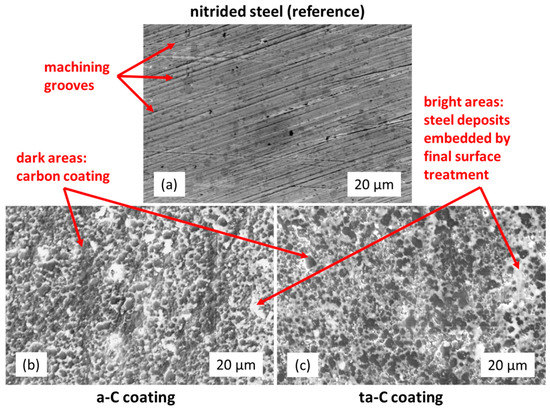
Figure 1.
SE images of initial surfaces: (a) nitrided steel, (b) a-C, and (c) ta-C coating.

Table 1.
Specification of used piston rings.
2.2. Test Bench Setup with Adjustable Oil Supply
General characteristics of the used test bench in this work have been already described in [27]. However, in this study an adjustable oil supply flow unit with a new temperature control and measuring system were implemented. The tribometer’s drive system is based on a standard crankshaft drive, exhibiting a stroke of 73 mm, from a mass-produced internal combustion engine (BMW “K21” motorbike boxer engine). The piston ring mount moves linearly in the horizontal direction, as indicated in Figure 2a, while the cylinder liner surface faces vertically downward. The horizontal movement from the TDC to the bottom dead centre (BDC) is referred to as ‘downward movement’, while the movement from the BDC to the TDC is referred to as ‘upward movement’. A threaded bushing applies the normal load Fn, compressing a spring, which pushes the piston ring towards the cylinder liner. A double piston high-performance liquid chromatography (HPLC)-pump was employed to precisely control the lubricant flow. This device permits the control of the lubricant flow from 1 µL/min to 10 mL/min. Figure 2a illustrates the lubricant dosage system with a two-substance vaporiser pointing towards the BDC of the cylinder liner and its pre-heating system in order to prevent temperature drops. The cylinder liner surface is wetted primarily as a result of the current lubricant at the BDC and the distribution over stroke guided by the piston ring and honing grooves. As a result, for stationary circumstances, the whole cylinder liner is uniformly wetted with lubricant. As illustrated, the alignment of the vaporiser is defined through the spacings a, b and the spray angle α. In this study, they are defined as follows: 3 mm for a, 21 mm for b, and about 1° for α.
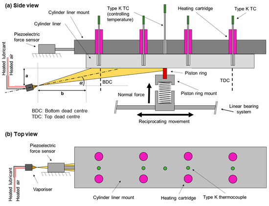
Figure 2.
(a) Side view of the test system’s schematic layout, including lubricant dosage, heating system, and thermocouple (TC) regulation, according to [27]. (b) Top view.
The cylinder liner mount made of aluminium was heated by eight uniformly distributed heating cartridges enabling temperatures up to 130 °C, see Figure 2a,b. A control loop to regulate the cylinder liner surface temperature was installed. It includes a central thermocouple (TC) at the backside of the cylinder liner segment and a thermal controller. The cylinder liner temperature was controlled with the central TC, which is positioned at the outer diameter of the cylinder liner segment to avoid a volatile system. Temperature offsets induced by the spatial distance between the TC and the cylinder liner surface are taken into account. Furthermore, additional four TCs were placed 1.5 mm below the surface of the cylinder liner. To eliminate the effects of ambient temperature fluctuations, the entire tribometer is completely encapsulated. Moreover, the aluminium’s thermal conductivity provides a consistent temperature in the cylinder liner mount and the cylinder liner itself. However, the temperature distribution of the cylinder liner was measured for several cases determining a maximum deviation of 3 °C over stroke length for stationary conditions.
2.3. Governing Equations of EHD-Simulation
In this work, the EHD simulation model developed for the combined test method as described in [27] was used. To examine the system’s whole dynamic behavior, Newton’s law of motion was solved within the flexible multibody system [32,33]. A double-sided EHD contact was used to model the nonlinear tribological contact between the ring and the cylinder liner, including all mutual dependencies between the fluid film and the flexible bodies. The gap height in the joint is directly influenced by the pressure-related deformation of both bodies enclosing the fluid film. Because of their full bilateral coupling, this has an effect on the computed pressure inside the Reynolds Equation.
The EHD software (AVL EXCITE POWER UNIT, Version number 2020 R2, AVL LIST GmbH, Graz A-8020, Austria) utilised can model hydrodynamic, mixed, and boundary lubrication while taking surface roughness into account. For this, the genuine three-dimensional surface roughness of the cylinder liner and the piston ring in runned-in condition were measured and simulated using the micro-contact analysis tool “Microslide” [34,35]. This tool evaluates the effect of surface roughness on shear and pressure flow as well as asperity contact as a function of gap height [33]. In the EHD-simulation, the obtained maps were utilised to calculate all relevant surface roughness effects on fluid flow and solid contact in the mixed or boundary lubrication regime. As an engineering surface, the cylinder-liner is cross-hatch honed and has a non-Gaussian distribution. Non-Gaussian flow factors were employed by Leighton et al. [36] for measured liner surfaces. However, in this study, the surfaces of the piston ring and cylinder liner were assumed to be Gaussian and measured surfaces in runned-in condition were used. Furthermore, the simulation took into account the genuine piston ring and cylinder liner surface contours in runned-in condition as well as the lubricant characteristics.
In the nonlinear EHD joint, the Reynolds Equation (1) for measured rough surfaces [37] with a fill ratio and mass conserving cavitation model [35,38,39] is solved to calculate the fluid film pressure [35]:
where θ denotes the fill ratio, φP the pressure flow factor, φS the shear flow factor, h is the nominal gap height, is the mean value of the local gap height between ring and liner, p the hydrodynamic pressure, is the oil starvation factor σ is the composite surface roughness and η is the dynamic viscosity.
2.4. Fired Engine Piston Assembly Friction Simulation
In [40] the measurement validated model of the fired single cylinder engine was introduced and described in detail, which was used in the present work to ensure that the frictional behaviour and the prediction of the top ring-related friction reduction potential were transferable from the tribometer to the piston top ring of the real engine. The simulation of the piston and piston ring pack friction of the real single cylinder engine was performed with AVL EXCITE POWER UNIT and AVL EXCITE PISTON & RINGS (Version number 2021 R1, AVL LIST GmbH, Graz A-8020, Austria) in a detailed multibody simulation (MBS) with flexible bodies and elastohydrodynamic (EHD) joints for the tribological contacts. In the piston ring dynamic analysis with three-dimensional piston rings, the piston’s secondary motion was considered. In the simulation all relevant physical effects were considered and showed good accordance with the measured friction forces on the fired single cylinder engine [40].
The model took into account the cylinder liner and piston profile shapes as fabricated, as well as thermomechanical deformations of them, piston ring profiles, and temperature-dependent lubricant characteristics. With precalculated pressure and shear flow factors as well as an asperity pressure map, the fluid film as well as the contacting solid asperity contacts for the real measured surfaces and their materials are completely considered in the EHD contacts. In a preprocessing step, contact stiffness and ratio were calculated using the AVL Microslide [34,35]. Real measured three-dimensional rough surfaces in a runned-in condition from engine tests were used for this purpose. The EHD’s friction model is introduced in [32,33,41] and uses boundary and viscous friction. The friction model for each tribosystem was calibrated using the reciprocating long-stroke tribometer [27] described in this paper.
2.5. Surface and Contour Characterisation
For quantifying the three-dimensional topography of the specimen surfaces at the micro- and nanoscale, a scanning electron microscope (SEM, Philips, FEI XL 20) with a quadruple secondary electron detector system [42] and the corresponding “DISS5” software were used. An accelerating voltage of 20 kV was applied and for the planar direction a resolution of 0.262 µm per pixel was chosen. Beside BSE and SE-images, as derived from classical SEM-analyses, the detector system also allows quantifying depths, heights, and roughness parameters. A vertical resolution of up to 10 nm is possible for the used system. Further information about the described method can be found elsewhere [43,44,45].
Contour measurements were performed using a “MarSurf Perthometer S2” (Mahr GmbH, 37073 Göttingen, Germany) with drive unit “PGK” and stylus tip “MFW 250”. For the axial direction a resolution of 0.5 µm per pixel was chosen.
3. Results and Discussion
3.1. Long-Stroke Tribometer Investigations
3.1.1. Derivation of Test Parameters
For the first specification of operating conditions and the estimation of operating parameters on the LST, the Gümbel–Hersey number [46,47] was used to approximate flow with mechanically similar operating conditions related to the top ring of a fired single cylinder engine. Such an analytical approach is used when detailed information about the operating conditions of the top ring are missing, such as the asperity contact pressure. Since this information cannot be determined analytically, EHD-simulations must be performed. The formerly derived Hersey number depends on dynamic viscosity, rotational speed, and (bearing) pressure comparing geometrically similar bearings that are similarly loaded and lubricated [46]. In our approach, a modified Gümbel–Hersey number (mGHN) was employed. This is necessary due to the difference in stroke between a single cylinder engine and the LST as well as to bypass a determination of interface pressures. The mGHN is defined as follows:
where U denotes the relative velocity, η the dynamic viscosity, and L the line load.
It is assumed that the entire combustion pressure p solely takes effect on the backside of the piston ring, pushing it towards the cylinder liner. The line load according to ICEs , see Equation (3), is derived from the combustion chamber pressure , the area on the backside of the piston ring , and the piston ring circumference length (). Similarly, the line load according to the LST is calculated with the applied normal load per piston ring circumference length in contact based on the used segments, respectively. Figure 3a shows the mGHN calculated for a single cylinder engine as described in [48] at 1500 rpm and 6 bar indicated mean pressure (IMEP). In this calculation, the cylinder liner temperature distribution is assumed to be homogenous at 120 °C and therefore the dynamic viscosity is constant over stroke.
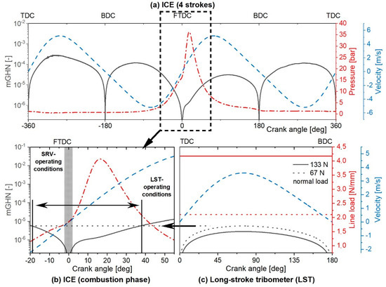
Figure 3.
Graphical comparison of operating conditions. (a) Modified Gümbel–Hersey number (mGHN) for the top ring of a single cylinder engine at 1500 rpm and 6 bar IMEP in dependence on relative velocity and combustion chamber pressure, (b) mGHN at combustion phase, and (c) for the LST at 900 rpm.
In the present case, the modified Hersey number operates from 10−7 up to 3∙10−4. According to Equations (2) and (3), the Hersey number tends towards zero at the reversal zones, because the top ring movement is suspended temporarily. In general, a large part of friction of the top ring emerges in the range of maximum combustion chamber pressure [40,49,50,51], or in this particular case between −20° up to a 65° crank angle, due to high pressures in the interface. For this reason, the tribometer operating parameters in terms of rotational speed, temperature, and normal load, are chosen in order to replicate the mGHN of the single cylinder engine for the combustion phase (compare Figure 3b,c). As a result, the LST covers approximately −18° up to a 37° crank angle. Compared to typically used short-stroke tribometers, e.g., SRV, the LST is able to cover a wider range of ICE operating conditions. The operating temperature for the LST is set to 120 °C replicating the temperatures in the region of maximum pressure. Therefore, the viscosity on the LST and on the single cylinder engine is assumed to be at the same level. Consequently, this permits a comparison based on the mGHN, which is independent of viscosity and therefore temperature.
3.1.2. Pilot Test on Lubricant Flow Rate
In order to reduce the number of LST tests, several lubricant flow rates must be defined. For this reason, a pilot test using the reference system (nitrided steel piston ring) was conducted. In the test phase, several oil lubricant flow rates were specified, covering 10 different oil supply rates. Beginning with a high lubricant flow rate of 1 mL/min, the rate was reduced stepwise by 40% until the minimum rate of 0.01 mL/min. Figure 4 shows the resulting COFRMS from LST depending on the lubricant flow rate. The error bars indicate the standard deviation of the last 100 cycles.
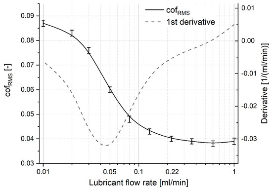
Figure 4.
Pilot test with nitrided steel piston ring (reference system, continuous line): COFRMS for lubricant flow rates ranging from 0.01 to 1 mL/min at 900 rpm and 133 N normal load.
The COFRMS is calculated as the friction coefficient per cycle or rather the root mean square of the crank angle resolved COF. This procedure is described in detail in current literature [27]. Beginning with 1 mL/min, the tribosystem exhibited a COFRMS of 0.039. For a wide range, lowering oil supply rate did not significantly influence the friction’s coefficient. However, an oil supply rate of 0.13 mL/min emerged as the threshold value, resulting in a COFRMS of 0.043. Further lowering entailed a drastic increase in friction. For example, for an oil supply rate of 0.05 mL/min the COFRMS was 0.06. With oil supply rates of 0.02 and 0.01 mL/min the COFRMS seemed to converge to 0.09. The COFRMS at these oil supply rates were at 0.083 and 0.087, respectively. The dashed line in Figure 4 shows the derivative of the COFRMS, illustrating the highest change in COFRMS at approximately 0.05 mL/min. It has to be noted, that in the course of reducing the lubricant flow rate from 1 to 0.01 mL/min, the COFRMS increased by 223% despite rotational speed and normal load remaining unchanged, revealing the importance of proper lubrication.
The mean cylinder liner temperature, measured as illustrated in Figure 2, was 119 °C for an oil flow of 1 mL/min, with a standard deviation in the stroke-direction of 3 °C. Similarly, at 0.01 mL/min the mean temperature was 121 °C with a standard deviation of 2.5 °C. Thus, for this study the cylinder liner temperatures can be assumed to be constant at approximately 120 °C.
3.1.3. Description of Test Procedure
For determining the influence of normal load and oil supply on friction, the test procedure was prepared. It consists of pre-oiling, running-in, and the test phase (see Figure 5), using different oil supplies. Therefore, the rotational speed was kept unchanged and the temperature was set to 120 °C for the entire procedure. A standardised preparation method based on [27] was conducted for each test run. After cutting and cleaning the test specimens with isopropyl alcohol and using an ultrasonic bath, the piston ring was aligned with respect to the cylinder liner using the light gap and low pressure sensitive Prescale films (from FUJIFILM) for 2.5–10 MPa that allow a visualisation of the pressure distribution.
Figure 5.
LST test procedure on basis of the pilot test, displaying the applied normal load, rotational speed, temperature, and lubricant flow rate.
The piston ring mount was used to manage the piston ring tension. If the pressure distribution appears to be homogeneous and the light gap between the piston ring and the cylinder liner has gone at any crank angle degree of crank shaft rotation, the alignment is sufficient. The test bench and lubricant dosage system were then heated to a specified temperature. The running-in seeks to achieve a steady-state condition in terms of the coefficient of friction (COFRMS) over time for various oil supply rates during the test phase. Furthermore, it is defined as sufficient if the operating conditions of 133 N and 1 mL/min at the beginning of the test phase are similar in terms of COFRMS at the end of the test phase (operating point reproducibility). The pre-oiling is used to ensure similar starting conditions for every tribosystem concerning oil supply inhibiting unwetted surfaces when applying high normal loads. It starts applying a lubricant flow rate of 10 mL/min for 10 min (see Figure 5), whereby a temporary normal load of 33 N is exerted. After that, the normal load is increased to 133 N and lubricant flow rates of 1 and 0.01 mL/min are applied to cover the maximum and minimum oil supply. Obert et al. [9] and Biberger and Füßer [52] specify an oil supply ranging from 0 to 1.0 µL/min (SRVIII) and 0.05 mL/min at a sliding speed of 1 m/s (rotational tribometer) for their tests. However, due to a diverging test setup and differently sized contact areas oil supply rates need to be greater for the LST.
The test phase seeks to compare different tribological systems. Every operating point within the test phase has a length of 15 min starting from the end of the run-in. Three different normal loads are applied. It starts at a normal load of 133 N, decreases to 100 N, and ends at 67 N. For each normal load value, the four lubricant flow rates, namely 1, 0.22, 0.05, and 0.01 mL/min, are applied starting with the highest value.
3.1.4. Influence of Oil Supply on Friction
In order to compare the tribological performance of the three tribosystems described in Section 2.1, a systematic description of the experimental results is presented in this section. COFRMS was plotted against the lubricant flow rate for the test phase as shown in Figure 6. It has to be mentioned that the systems always underly manufacturing tolerances, alignment, and always slightly different framework conditions. The tribosystems’ repeatability in dependence on the variable oil supply was validated carrying out three separate tests for every tribosystem using new components including a one-time realignment of the vaporiser serving the lubricant. The realignment was tested to proof the repeatability of the oil supply.
Figure 6.
COFRMS for different piston rings as a function of normal load, coating, and lubricant flow rate ranging from 0.01 to 1 mL/min. For a better visibility the grey area illustrates the repeatability in form of the standard deviation from the reference system. The repeatability of the ta-C and a-C coated systems are indicated with error bars.
Beginning with 1 mL/min at the 67 N normal load, the reference system exhibited a COFRMS of 0.034 and the ta-C and a-C coatings exhibited a COFRMS of 0.027 and 0.031, respectively. These values indicate well-lubricated systems. Reducing the lubricant flow rate to 0.22 mL/min resulted in an increase in COFRMS to 0.042 for the reference and 0.035 for the a-C coating. The COFRMS for the ta-C raised to 0.030. For this flow rate, the friction for the ta-C coating was 30.2% and for the a-C coating it was 16.4% lower compared to the reference. The further lowering of oil supply to a lubricant flow rate of 0.05 mL/min pushed the COFRMS noticeably to 0.063, 0.044, and 0.053 for the reference, the ta-C, and a-C coating systems, respectively. At this point, the friction for the ta-C coating was 27.3% and for the a-C coating 17.0% lower compared to the reference system. At 0.01 mL/min, the COFRMS raised progressively up to 0.079, 0.061, and 0.072 for the reference, the ta-C, and the a-C coating, respectively. Here, the advantage of the ta-C coating compared to the reference system dropped to 20.2%, while the favourable difference of the a-C coating decreased to 8.5%. However, the influence of the lubricant flow rate is enormous, since the COFRMS has more than doubled with the decreased oil supply for all three evaluated systems.
For the 100 N normal load and a lubricant flow rate of 1 mL/min, the three systems reported COFRMS of 0.033, 0.027, and 0.030 for the reference, the ta-C, and the a-C coating, respectively. For 0.01 mL/min, the values increased to 0.081, 0.060, and 0.073, for each case. Again, the ta-C coating yielded a friction improvement of 31.0% and 30.8% and the a-C coating 15.7% and 24.3% for 0.05 and 0.22 mL/min.
For the 133 N normal load and a lubricant flow rate of 1 mL/min, COFRMS of 0.036, 0.033, and 0.032 were measured for the reference, the ta-C, and the a-C coating, respectively. For 0.01 mL/min, the values increased to 0.084, 0.064, and 0.075, for the aforementioned systems.
As illustrated in Figure 7, the ta-C and a-C coating exhibit an averaged improvement in friction compared to the reference system of 24 and 12%, respectively. It can be concluded that both the coating as well as the lubricant flow rate, have a significant impact on friction. Moreover, the ta-C coating showed a relatively high deviation in terms of tribosystem repeatability in general compared to the other systems (see Figure 6 and Figure 7). The explanation for it can be related to the high wear resistance resulting from the diamond-like hardness (5000 HV). In consequence of the high wear resistance, the alignment of the top ring cylinder liner conjunction is more relevant for the running-in phase because an adaption of the piston ring contour is hindered during the running-in. This can cause local pressure peaks leading to a higher deviation in terms of friction for the ta-C coating. However, when reiterating the first operating point in the test phase (operating point reproducibility), see the Figure 5 last operating point, the discrepancy between them is 0.005, 0.007, and 0.003 in terms of COFRMS for three systems investigated. Therefore, the running-in is sufficient within the framework of this study.
Figure 7.
Mean values and standard deviations for the whole test phase for all three tribosystems tested.
3.2. Topography and Piston Ring Contour Analysis
As contours and topography are necessary for the simulation, and the coatings offer an improved wear resistance, wear and surface properties are described in this section. In the following, one representative pair of piston ring and cylinder liner from each of the three different tribosystems are chosen for quadruple secondary electron detector SEM analysis and the subsequent numerical studies. The analysis consists of a topography measurement of both the piston ring and cylinder liner in each case, and a piston ring contour measurement.
3.2.1. Piston Ring Contour and Wear
Representative contours after tribological tests are shown in Figure 8a. In addition, the wear heights from Figure 8b were determined by comparing the worn piston ring contour with a counter measurement of an unworn piston ring in each case. Compared to the nitrided piston ring (reference) with an absolute abrasion height of 1.4 µm, an 86 and 57% lowered abrasion height was measured for the ta-C and the a-C coatings, respectively. Furthermore, the wear coefficient, determined according to Archard and Hirst [53], and the abrasion height per testing time (wear rate) of the entire test procedure, including the running-in, were determined for the piston rings as stated in Table 2. The wear volume was approximated with a circular function that describes the convexity of the unworn piston ring. The low overall wear rates again indicate a sufficient running-in, although the running-in is included in calculating the wear rates.
Figure 8.
Piston ring contours after tribo test in running-in condition (a) and abrasion height (b). The abscissa in (a) represents the sliding direction and the highest point marks the neutral axis.
Table 2.
Roughness characteristics of worn specimens from quadruple secondary electron detector system and wear characteristics after tribotest.
Wear characteristics for the cylinder liners could not be determined due to non-quantifiable traces of wear for all the systems. It has to be mentioned that the wear tracks on the tested cylinder liners were visible, denoted by a change of surface colour. However, because of the small contact engagement ratio between the piston ring and the cylinder liner, cylinder liner wear is of less concern and not further analysed in this study.
3.2.2. Topography and Roughness
Before the topographical SEM analysis was performed, the specimens were cleaned using isopropyl alcohol and an ultrasonic bath. The a-C- and ta-C-coated specimens were additionally sputtered with gold before SEM analysis, to improve the rate at which electrons are backscattered by the carbon coatings. The topography raw data were levelled by shape removal as well as by using a high pass filter with a 50 µm wavelength for the piston rings and a 250 µm wavelength for the cylinder liners within the micro-contact analysis software “Microslide” to remove the waviness. The remaining size of a surface sample was 470 µm in the circumferential direction and 250 µm in the stroke direction. Table 2 shows the results from topography analysis of the used specimen in running-in condition. Owing to the large contact area, representative surfaces in the middle of the contact area of each specimen were chosen for this study. The root mean square roughness of the piston rings (Sq,PR) were below 100 nm for all three systems and the contact zones of the ta-C and a-C coatings were smoother than those of the nitrided steel. In contrast, the cylinder liners exhibited a higher Sq in general and valley depths (Svk) that are due to the specimens’ porosity larger than the Sq itself. At this point, a more detailed comparison could be utilised covering further functional parameters in the future, e.g., as described by Yousfi and Ţălu [54]. However, due to the tribological stress, the root mean square roughness of the cylinder liners (Sq,CL) in running-in condition were in general smaller for all the tested systems compared to the initial roughness (~0.97 ± 0.25 µm, see Section 2.1). Therefore, for further numerical studies it was assumed that the roughness did not change during the test phase, due to the negligible discrepancy when replicating the first operating point (operating point reproducibility) in the test phase, as explained in the test procedure, and the sufficient running-in.
3.3. Numerical Studies on Basis of the Tribometer Results
Subsequent simulative investigations were performed to model the tribological behaviour of the experimentally investigated tribosystems. The aim of these simulations was to reveal the tribosystem internal operating conditions influencing the frictional behaviour, e.g., asperity contact and hydrodynamic pressure. The internal operating conditions were permitted to compare the tribosystems in detail. Thus, the experimental friction results were complemented. Another advantage was the evaluation of different boundary conditions, such as, e.g., differently sized contact areas. However, such an issue of an experimentally not assessable impact of differently sized contact areas is, e.g., mentioned in [23,25].
3.3.1. Definition of the Oil Supply Parameter
Systematic simulations were performed to model the influence of the oil supply on asperity contact and hydrodynamic pressure for the three systems. The main influencing factor for starvation is a reduced inlet oil supply [15]. In this study, starvation was enforced by limiting the amount of lubricant that is supplied to the contact. Along with a subsequent drop of hydrodynamic pressure in the interface, the ability to separate the surfaces’ asperities vanishes and therefore friction increases. The following investigations were performed by varying the boundary condition of the inlet oil film thickness hoil for a normal load of 100 N.
3.3.2. Crank Angle Resolved Results for Fully Flooded and Starved Lubrication Conditions
In order to analyse the dependence of friction on oil supply, a representative operating condition for both fully flooded and starved conditions was selected from the reference system. In Figure 9, exemplary crank angle resolved results of the reference system are illustrated for both lubrication conditions. For the simulation, the inlet oil film thickness boundary condition was kept constant for the whole 360° crank angle. The resulting asperity contact and hydrodynamic pressure was averaged for the whole tribocontact zone.
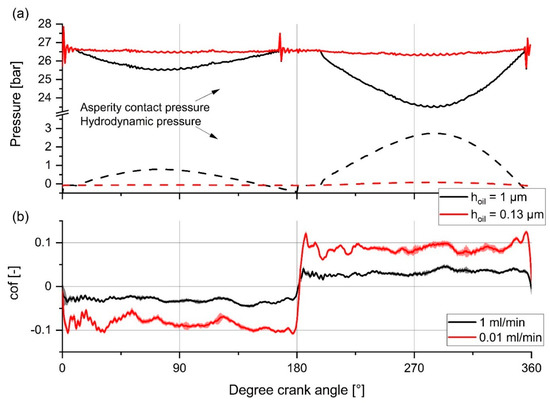
Figure 9.
Comparison of (a) Crank angle resolved interface pressures in dependence on the oil supply for the nitrided piston ring (reference) and (b) corresponding friction from the experiments (for 100 N of normal load).
As an example, the continuous lines in Figure 9a specify the asperity contact pressure for the reference system at 100 N of the normal load, whereas the dashed lines specify the hydrodynamic pressure. The red and black colours differentiate between fully flooded and starved lubrication conditions. However, with the boundary condition of an inlet oil film thickness of 1 µm, the asperity contact pressure decreased because of the hydrodynamic pressure build-up, especially at the peak relative velocities (75 and 285° crank angle). On the other hand, no significant hydrodynamic pressure build-up was achieved for the boundary condition of an inlet oil film thickness of 0.13 µm, resulting in an almost steady asperity contact pressure over the crank angle.
Additionally, Figure 9b shows the experimentally measured COF over the crank angle for lubricant flow rates of 1 and 0.01 mL/min for a whole cycle. A negative prefix indicates the sliding direction, and as usual for measured data, the COF is superimposed by negligible measurement errors because of vibrations. For 1 mL/min, the COF exhibited an approximate value of 0.032 (see also Figure 6) and did not change significantly over the crank angle. In contrast, for 0.01 mL/min of oil flow, the COF in general exhibited higher values of ~0.08 (from 20 to 160° and 200 to 340° crank angles). Additionally, the COF exceeded the value of 0.1 (+25% on top), especially in the reversal zones at 0, 180, and 360° crank angles. The higher COF values could be related to the lower hydrodynamic pressure in combination with absent friction modifiers. A possible explanation about the increased COF, especially in the reversal zones, could be a prevalence of boundary friction assigned to absent friction modifiers at small relative velocities. For an overlubricated contact (1 mL/min lubricant flow rate) the interaction with the additives seems to be dominant compared to a hydrodynamic pressure build-up. Further investigations are necessary to explain these results. For this reason, the investigations as follows were performed. Since the mean asperity contact pressure and hydrodynamic pressure significantly changed with the sliding speed, the following numerical investigations focus on the 285° crank angle to show the major differences.
3.3.3. Hydrodynamic Pressure Evolution in Dependence on the Oil Supply Parameter
The calculated hydrodynamic oil film pressure for the three investigated systems as a mean value for each top ring in contact is shown in Figure 10 as a function of inlet oil film height. For a low level of inlet oil film with a height of 0.06 µm, the hydrodynamic pressure dropped to almost zero for all systems. Starting with an inlet oil film thickness of 0.13 µm, the ta-C-coated piston ring built up significant hydrodynamic pressure support, simultaneously with increasing inlet film thicknesses. Its hydrodynamic pressure build-up evolves to approximately a 0.27 µm inlet oil film thickness. The difference in terms of hydrodynamic pressure between starved and fully flooded lubrication was 4.2 bar. Furthermore, the a-C-coated piston ring generated a significant pressure build-up in the range of 0.252 µm to 0.42 µm inlet oil film thickness, comprising an increase of 3.92 bar. Finally, the nitrided piston ring (reference system) started to generate a significant pressure build-up at 0.42 µm and the build-up flattens in the range of 0.6 µm inlet oil film thickness, resulting in an increase of 2.56 bar. Besides the lower pressure build-up of the nitrided piston ring, this system achieved 38% less hydrodynamic pressure as compared to the ta-C coating, and 34% less hydrodynamic pressure compared to the a-C-coated piston ring, for fully flooded lubrication conditions. Furthermore, the a-C-coated piston ring produced 6.4% less hydrodynamic pressure in comparison to the ta-C-coated piston ring. However, as a result of the specimens’ properties after tribotest, as described in Section 3.2, the material properties, as referred to in Section 2.1, and the applied tribological stress, the ta-C-coated piston ring rendered the highest hydrodynamic pressure as well as it started to establish hydrodynamic pressure at the lowest inlet oil film thickness. The a-C-coated piston ring performed similar to the ta-C-coated variant apart from a delayed pressure build-up in terms of minimum inlet oil film thickness concomitant with a lowered maximum pressure. In contrast, the nitrided piston ring showed the most gravely delayed pressure build-up and the lowest maximum pressure. Furthermore, the slopes of the pressure build-up for ta-C- and a-C-coated piston rings demonstrated a sharper transition in relation to the nitrided piston ring.
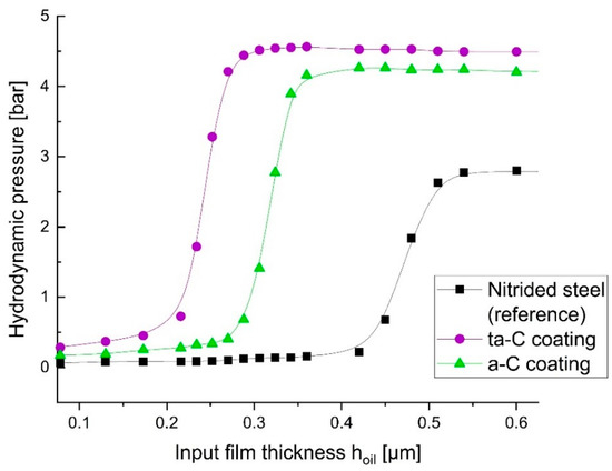
Figure 10.
Hydrodynamic pressure evolution with increasing oil supply. Results for 100 N normal load.
In general, the hydrodynamic pressure primarily depends on the piston ring contour, as e.g., investigated by Morris [18], for similar properties in topography. Due to manufacturing tolerances and the subsequent treatment (nitriding and coating) of the piston rings, slightly different initial contours are unavoidable. In this study, piston rings with preferably similar contours were chosen based on visual inspection.
As illustrated in Figure 8b and mentioned before, wear heights depend on the coating. Moreover, due to the different wear performances, the contours of the piston ring variants in running-in condition differ, see Figure 8a. This can be related to properties such as abrasion resistance. As a result, the hydrodynamic pressure and subsequently the interactions in the lubrication gap, e.g., gap width and asperity pressure, are influenced. On the other hand, hardness impacts the micro contact mechanics, which also has an impact on the interactions in the lubrication gap. Consequently, abrasion resistance and hardness are not directly related to the coefficient of friction. However, the significantly lowered wear of the amorphous carbon coatings, compared to the nitrided piston ring, supported hydrodynamic pressure build-up as well as lowered the minimum inlet oil film thickness. This could be related to, in a large part, the maintained convexity of the piston ring contour. The higher the wear, the more the piston ring contour loses its convexity and the more discontinuities, e.g., edges, are present, as indicated in Figure 8a by comparing the ta-C with the nitrided steel ring contour. It is assumed that a worn convexity and discontinuities interfere with the hydrodynamic pressure build-up. At this point, further simulations could be carried out.
3.3.4. Asperity Contact Pressure Evolution in Dependence on the Oil Supply Parameter
In addition to the hydrodynamic pressure, the asperity contact pressure was calculated, as shown in Figure 11. As it can be seen from the image, the evaluated systems operated under different asperity contact pressures from the beginning of the oil supply, at an inlet oil film thickness of 0.1 µm. In the case of starved conditions, the ta-C- and a-C-coated rings as well as the nitrided piston ring exhibited an asperity contact pressure of 24.4, 26.5, and 25.6 bar, respectively. In general, asperity contact pressure is affected by the deformation of the piston ring contour, roughness, and hydrodynamic pressure. However, with an increasing oil supply, the asperity contact pressures dropped to 20.3, 23.0, and 23.5 bar, respectively. The asperity contact pressure dropped, induced by an increasing hydrodynamic pressure, as shown in Figure 10. The reason for this is that the normal load applied on the piston ring is carried by both asperity contact and hydrodynamic pressure in the tribocontact zone. Equivalently to the hydrodynamic pressure, the ta-C-coated piston ring went through exceedingly large changes of asperity pressure, whereas the nitrided piston ring showed the lowest pressure difference.
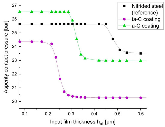
Figure 11.
Asperity contact pressure evolution with increasing oil supply. Results for 100 N normal load.
Compared to the extent of hydrodynamic pressure (Figure 10), the asperity contact pressure obviously plays the predominant role for all three systems. Nevertheless, the hydrodynamic contribution is about 17% for the ta-C system and around 13% for the a-C coated system in fully flooded lubrication conditions and is therefore relevant. On the other hand, the hydrodynamic contribution for the nitrided piston ring is significantly lower at about 8%. Despite that, the friction coefficients of the three systems in fully flooded conditions are quite similar and the friction coefficients of the three systems diverge with the reduced oil supply.
3.3.5. Measured Friction Versus Asperity Contact Pressure for Fully Flooded and Starved Lubrication Conditions
For further investigations and for the simulative prediction of friction losses, e.g., in ICEs, calibrated friction models are necessary [27,32,41]. The friction model considers boundary friction in the simulation including the effects of friction modifiers. It needs to be calibrated by experimental tests and is predominantly affected by the asperity contact pressure [32]. However, for the same lubrication conditions, usually only one calibrated friction model is necessary (as exemplarily demonstrated in [27]). In this study, one calibrated friction model is not sufficient for the different lubricant flow rates tested. For this reason, the general experimental results are compared to the general simulative results and possible reasons are discussed in this section.
Figure 12 shows the measured COFRMS for 0.01 and 1 mL/min lubricant flow rates depending on the calculated asperity contact pressure (according to Figure 11), in both fully flooded and starved lubrication conditions.
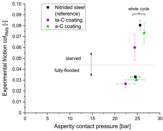
Figure 12.
COFRMS depending on the calculated asperity contact pressure for 100 N normal load.
As discussed in the previous sections, the friction coefficient depends to a large degree on the oil supply. For starved lubrication conditions, the COFRMS for all three systems is located above 0.045 at asperity contact pressures between 24.4 and 26.5 bar. For these lubrication conditions the following findings can be described:
- The COFRMS for the three systems differs significantly;
- The systems operate with almost similar asperity contact pressures;
- No crank-angle resolved effects are captioned, despite a slight increase in friction in the reversal zones, as exemplarily shown in Figure 9b at a 0.01 mL/min lubricant flow rate.
With a fully-flooding oil supply (fully flooded lubrication conditions);
- The absolute difference in COFRMS between the tribosystems drops;
- No exceptional crank-angle resolved effects in friction (COF) are captioned, as exemplarily shown in Figure 9b at a 1 mL/min lubricant flow rate;
- Crank-angle resolved effects in asperity contact pressures occur resulting in a wider range from 20.3 to 26.5 bar depending on the velocity (crank angle), as exemplarily shown in Figure 9a for an inlet oil film thickness of 1 µm;
- For the reversal zones asperity contact pressures remain at the same values for starved conditions (on the bottom right in the diagram);
- And for a 285° crank-angle or higher velocities, the COFRMS remains unaffected, while asperity contact pressures drop as far as 17% (for the ta-C-coated piston ring).
In summary, the varying hydrodynamic contribution, and consequently the varying asperity contact pressure, cannot solely be responsible for the change in friction during oil supply variation. De facto, the dependence of the friction coefficient on oil supply rate should in a large part be the result of additives such as, e.g., molybdenum dithiocarbamate (MoDTC) and zinc-dialkyldithiophosphate (ZDDP). Regarding MoDTC, Bouchet et al. [55] made investigations with MoDTC and ZDDP and DLCs in comparison to steel, and summarised that at a very low MoDTC concentration MoS2 single sheets cannot grow to a sufficient size to cover the asperities for efficient friction reduction (tribofilm formation). In particular, the MoDTC additive of the lubricant performs a tribochemical reaction forming MoS2 single sheets, when asperity contact occurs and MoDTC additives are present in the contact zone [56]. MoS2 single sheets are a solid lubricant exhibiting planes of high strength, while in a direction normal to these planes atoms are far apart and bondings are relatively weak [57]. If accumulated in the tribocontact zone, MoS2 sheets form a tribofilm layer on the surface with a low interfacial shear strength. Furthermore, they are able to cover asperities and thus avoid a direct contact of the surfaces. As a result of this, friction is lower when MoS2 single sheets are present in the contact zone, in particular on the contacting asperities. Because of starved lubrication, the interfacial shear strength increases traceable due to this missing surface layer with a lowered interfacial shear stress. Consequently, the beneficial tribological properties of the carbon coatings could become more apparent, when the surfaces come in direct contact (starved conditions), e.g., due to self-passivation, rehybridization processes, or the formation of planar graphene-like structures as discussed in [23]. For this case, amorphous carbon coatings (a-C and ta-C) offer a lower shear force compared to nitrided steel, where adhesion occurs. However, the difference in tribological performance between a-C and ta-C could be a result of hard Mo-carbide containing tribofilms accelerating wear, and possibly friction, but not with harder DLC (ta-C) [58]. Concludingly, an X-ray photoelectron spectroscopy (XPS) or electron energy loss spectroscopy (EELS)-analysis with the worn specimen surfaces coupled with molecular dynamic simulations could be carried out. Furthermore, advanced friction models could be used, e.g., as proposed by Xiuyi et al. [59], to improve the predictability of friction in the case of occurring tribofilm formation and removal.
In contrast to the SRVIII-investigations conducted by Obert et al. [9], an important effect of oil supply on friction was found. Obert used normal loads of about 100 N corresponding to Diesel engines, for a stroke length of 3 mm, a ring to liner contact length of 10 mm and a ring height of 1 mm. This in combination with less velocity results in much higher tribological stresses, due to smaller contact areas and higher normal loads. Consequently, the tribosystems operate in more harsh boundary conditions compared to the long-stroke tribometer used in this study. Along with the resulting higher wear, we believe that Obert was not able see an impact of oil supply rates on friction due to possible fretting conditions. At this point it has to be mentioned that Obert had the focus on scuffing behaviour and not friction.
In other studies, Makowski et al. [25] and Lafon-Placette et al. [60] reported tribochemical wear for hydrogen-free amorphous carbon coatings (such as ta-C) for elevated temperatures (above 100 °C) and the presence of a chemical active counter body material. This tribochemical wear could be induced by sulphur contamination and high local contact pressures, as reported by Ruiz et al. [61]. In [23] it is estimated that the tribochemical wear mechanisms are of less concern for applications with suitable counter body materials. However, because of the low wear of the amorphous carbon coatings measured in comparison to the nitrided piston ring, it can be estimated that the tribochemical wear mechanisms are of less concern for the tribometer tests reported here.
3.4. Comparison to Fired Single Cylinder Engine
In [40], experimentally validated piston assembly friction simulations for a fired single cylinder engine are carried out to investigate the friction reduction potentials of differently coated top rings. For the single cylinder engine test, the top rings only were amended, and the tests were conducted for multiple times, ensuring a valid comparison. Furthermore, they were carried out at a coolant and oil temperature of 90 °C on the engine inlet; however, a pre-investigation of these differently coated top rings with a focus on friction reduction potentials was performed in this study using the long-stroke tribometer. Tribosystems of the same type are used for both, the single cylinder engine and the tribometer, see Section 2.1. The single test bench and its “instantaneous IMEP-method” to measure the piston group friction and detailed operating conditions as well as simulation boundary conditions are described in [40,48]. As already described in the present tribometer-based work, a mean friction benefit for starved lubrication conditions of 24% and 12% is found for ta-C- and a-C-coated piston rings (see Figure 7), respectively. In the following, a comparison of COF values yielded by experimentally validated single cylinder tests with those derived by tribometer tests is performed to evaluate the ability of predicting the top rings frictional behaviour on the long-stroke tribometer.
3.4.1. Validation of Experimental and Simulative Results
The measurement validated simulation models for the fired single cylinder engine test bench were evaluated for the operation point at 1500 rpm and 6 bar IMEP with a deactivated piston cooling nozzle. They consider all relevant physical effects (see Section 2.4) and are validated by a comparison of the measured and simulated piston assembly friction. The results are reported in [40], showing a good agreement in general. The operation point of the fired single cylinder engine at 1500 rpm and 6 bar IMEP shows, in both the simulation and the measurement, the friction reduction potentials for ta-C and a-C coatings compared to the reference. In particular, the relative difference in friction reduction of ta-C coating and the reference in the simulation is 5.8% and 4% in the measurement. For the a-C coating, the relative difference in friction is 6.6% in the simulation and 8% in the measurement.
The simulation also allows to determine detailed component-related friction results for each tribological contact separately, e.g., for the top ring shown in Figure 13. As illustrated, the top ring shows a load-dependent behaviour because of gas pressure-induced loads. Therefore, for a major part of the total top ring friction, the asperity contact friction during the combustion cycle demonstrates a good potential for friction reduction by amorphous carbon coatings.
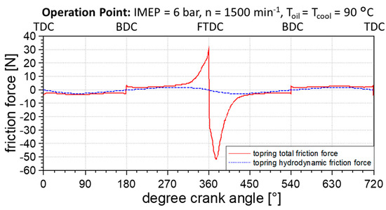
Figure 13.
Breakdown of friction force for a-C-coated top ring cylinder liner contact.
3.4.2. Friction Coefficients from Top Ring Variants
In contrast to the experimental investigation, detailed friction results for each tribological contact are evaluable as a result of the piston assembly friction simulations. The evaluation of the top rings frictional behaviour predictability on the long-stroke tribometer bases on a comparison of the friction coefficients from both testing methods.
Firstly, the comparison of the friction coefficients for the simulated top ring variants clearly shows the friction reduction potential of the coatings in the fired single cylinder engine because the friction coefficient for the ta-C and a-C coatings are lower than for the reference, see Figure 14. Therefore, beneficial friction properties could be confirmed for the DLC coatings.
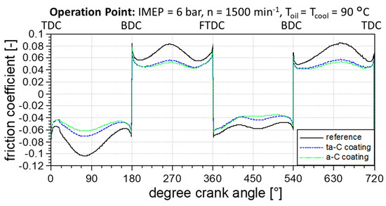
Figure 14.
Calculated friction coefficient for top ring cylinder liner contact versus crank angle.
Secondly, the friction coefficients operate in similar ranges compared to the tribometer tests showed in Figure 12 for starved lubrication conditions. This indicates a well working preselection on the tribometer using the mGHN, when testing starved lubrication conditions. In case of model-based friction measurements for the preselection of tribosystems, the influence of the oil supply must be considered.
Finally, from Figure 14 it is also possible to see that slightly higher friction coefficients were measured at higher velocities for the ta-C than for the a-C coating, in contrast to the tribometer results. This is due to an increased hydrodynamic friction driven by different piston ring contours and roughness. The investigation of the piston ring contours and the associated roughness from the single cylinder engine are not part of this study. Therefore, further investigations to examine the comparability of a single cylinder engine and long-stroke tribometer are necessary.
4. Conclusions
In this study, long-stroke tribometer tests were carried out for analysing the crank angle resolved friction behaviour of the top ring in combination with an EHD-simulation analysis of the tribometer to predict and investigate the frictional behaviour and the contact conditions. To verify the applicability of the tribometer test to the fired single cylinder engine, the top ring related friction was compared.
In this frame, the dependence of oil supply on friction was investigated for nitrided and a-C/ta-C-coated piston rings. The most relevant findings of this research are listed below:
- Ultra-low friction coefficients (COF < 0.04) were measured for fully flooded lubrication conditions for all evaluated piston rings. At high velocities (900 rpm and a 285° crank angle) the hydrodynamic pressure noticeably reduced contact pressure with a negligible impact on the COF.
- The a-C and the ta-C coating showed beneficial friction and wear properties compared to the nitrided steel piston ring on series-produced cylindrical liners with thermally sprayed iron-based alloy coatings.
- For each piston ring variant, a critical value for the minimum inlet oil film thickness was found. Exceeding this specific value provoked a significant asperity contact pressure increase. Furthermore, this behaviour was strongly linked to the piston ring contour.
- Reducing the oil supply resulted in a significant friction increase for all piston rings, demonstrating the huge impact of oil supply. For starved lubrication conditions, a friction reduction of 24% and 12% was measured for ta-C- and a-C-coated piston rings, respectively.
- The lowest piston ring wear was measured during the deployment of the ta-C-coated piston ring. This coating variant also performed significantly better than the nitrided steel piston ring. Due to the low wear of the DLC coatings compared to the nitrided steel piston ring, no critical wear processes could be noticed. The DLC coating surfaces were in general smoother in a worn condition.
- The hydrodynamic pressure is indirectly linked to abrasion resistance and therefore hardness, due to the conservation of piston ring contour convexity.
The investigations on the tribometer were performed as a pre-investigation for subsequent single cylinder analyses. The knowledge gained by the comparison between the tribometer and single cylinder engine can be summarised as follows:
- Friction reduction potentials of both carbon coatings, ta-C and a-C, were confirmed.
- No ultra-low friction (COF < 0.04) was measured on the single cylinder engine in contrast to the tribometer. However, COF measured on the tribometer becomes similar to the fired single cylinder engine when starved lubrication conditions are applied.
- In contrast to the tribometer, the a-C-coated piston rings performed slightly better than the ta-C-coated specimen. In addition, both DLC coatings performed better than the nitrided steel piston ring. Therefore, a general preselection of piston rings concerning their frictional behaviour on the long-stroke tribometer is possible and the derivation of tribometer test parameters on the basis of the GHZ works for similar lubrication conditions.
Author Contributions
B.M.: conceptualization, methodology, investigation, validation, software, project administration, writing—original draft, visualisation, writing—review and editing. D.J.: writing—original Draft, writing—review and editing, visualisation, validation, software. A.H.: investigation. P.S.: data curation, visualisation. B.K.: funding acquisition, resources. F.-J.W.: formal analysis, funding acquisition. A.L.: formal analysis, supervision. A.F.L.: formal analysis, supervision. All authors have read and agreed to the published version of the manuscript.
Funding
This research was funded by the Federal Ministry for Economic Affairs and Climate Action grant number 03ET1609I.
Institutional Review Board Statement
Not applicable.
Informed Consent Statement
Not applicable.
Data Availability Statement
Data available on request due to restrictions/data sharing not applicable.
Acknowledgments
This publication uses results from a project that has been funded by the Federal Ministry for Economic Affairs and Climate Action (BMWK) with funding reference 03ET1609I. The author is responsible for the content of this publication. The authors would like to thank A. Götze (Chair of Combustion Engineering and Drive Technology, Technische Universität Dresden) for the allocation of single cylinder engine measurement data, S. Hoppe, M. Kennedy, and G. Englberger (Federal-Mogul Deutschland GmbH) for the supply of piston rings, V. Weihnacht, and F. Kaulfuß (Fraunhofer Institute for Material and Beam Technology IWS) for the coating of piston rings, and R. Luther, and J. Rausch (FUCHS SCHMIERSTOFFE GMBH) for the provision of lubricants. The authors thank H. Aydin and E. Schäfer (Steinbeis) for the test rig measurements and topography analyses.
Conflicts of Interest
The authors declare no conflict of interest.
References
- Kennedy, M.; Hoppe, S.; Esser, J. Kolbenringbeschichtung zur Reibungssenkung im Ottomotor. MTZ-Mot. Z. 2012, 73, 400–403. [Google Scholar] [CrossRef]
- Richardson, D.E. Review of Power Cylinder Friction for Diesel Engines. J. Eng. Gas Turbines Power 2000, 122, 506. [Google Scholar] [CrossRef]
- Holmberg, K.; Andersson, P.; Erdemir, A. Global energy consumption due to friction in passenger cars. Tribol. Int. 2012, 47, 221–234. [Google Scholar] [CrossRef]
- Worton, D.R.; Isaacman, G.; Gentner, D.R.; Dallmann, T.R.; Chan, A.W.H.; Ruehl, C.; Kirchstetter, T.W.; Wilson, K.R.; Harley, R.A.; Goldstein, A.H. Lubricating oil dominates primary organic aerosol emissions from motor vehicles. Environ. Sci. Technol. 2014, 48, 3698–3706. [Google Scholar] [CrossRef]
- Pirjola, L.; Karjalainen, P.; Heikkilä, J.; Saari, S.; Tzamkiozis, T.; Ntziachristos, L.; Kulmala, K.; Keskinen, J.; Rönkkö, T. Effects of fresh lubricant oils on particle emissions emitted by a modern gasoline direct injection passenger car. Environ. Sci. Technol. 2015, 49, 3644–3652. [Google Scholar] [CrossRef] [PubMed]
- Rahmani, R.; Rahnejat, H.; Fitzsimons, B.; Dowson, D. The effect of cylinder liner operating temperature on frictional loss and engine emissions in piston ring conjunction. Appl. Energy 2017, 191, 568–581. [Google Scholar] [CrossRef] [Green Version]
- Esser, J. Oil control rings and their effect on oil consumption. MTZ Worldw. 2002, 63, 22–25. [Google Scholar] [CrossRef]
- Sanda, S.; Murakami, M.; Noda, T.; Konomi, T. Analysis of Lubrication of a Piston Ring Package. (Effect of Oil Starvation on Oil Film Thickness). JSME Int. J. Ser. B Fluids Therm. Eng. 1997, 40, 478–486. [Google Scholar] [CrossRef] [Green Version]
- Obert, P.; Müller, T.; Füßer, H.-J.; Bartel, D. The influence of oil supply and cylinder liner temperature on friction, wear and scuffing behavior of piston ring cylinder liner contacts—A new model test. Tribol. Int. 2016, 94, 306–314. [Google Scholar] [CrossRef]
- Liu, Z.; Liang, F.; Zhai, L.; Meng, X. A comprehensive experimental study on tribological performance of piston ring–cylinder liner pair. Proc. Inst. Mech. Eng. Part J J. Eng. Tribol. 2022, 236, 184–204. [Google Scholar] [CrossRef]
- Courtney-Pratt, J.S.; Tudor, G.K. An Analysis of the Lubrication between the Piston Rings and Cylinder Wall of a Running Engine. Proc. Inst. Mech. Eng. 1946, 155, 293–299. [Google Scholar] [CrossRef]
- Shin, K.; Tateishi, Y.; Furuhama, S. Measurement of Oil-Film-Thickness Between Piston Ring and Cylinder. SAE Trans. 1983, 92, 187–201. [Google Scholar]
- Mohammadpour, M.; Johns-Rahnejat, P.M.; Rahnejat, H.; Gohar, R. Boundary Conditions for Elastohydrodynamics of Circular Point Contacts. Tribol. Lett. 2014, 53, 107–118. [Google Scholar] [CrossRef] [Green Version]
- Shahmohamadi, H.; Mohammadpour, M.; Rahmani, R.; Rahnejat, H.; Garner, C.P.; Howell-Smith, S. On the boundary conditions in multi-phase flow through the piston ring-cylinder liner conjunction. Tribol. Int. 2015, 90, 164–174. [Google Scholar] [CrossRef] [Green Version]
- Bewsher, S.R.; Mohammadpour, M.; Rahnejat, H.; Offner, G.; Knaus, O. An investigation into the oil transport and starvation of piston ring pack. Proc. Inst. Mech. Eng. Part J J. Eng. Tribol. 2019, 233, 112–124. [Google Scholar] [CrossRef]
- Wakuri, Y.; Hamatake, T.; Soejima, M.; Kitahara, T. Piston ring friction in internal combustion engines. Tribol. Int. 1992, 25, 299–308. [Google Scholar] [CrossRef]
- Seki, T. A study on variation in oil film thickness of a piston ring package: Variation of oil film thickness in piston sliding direction. JSAE Rev. 2000, 21, 315–320. [Google Scholar] [CrossRef]
- Morris, N.; Rahmani, R.; Rahnejat, H.; King, P.D.; Fitzsimons, B. The influence of piston ring geometry and topography on friction. Proc. Inst. Mech. Eng. Part J J. Eng. Tribol. 2013, 227, 141–153. [Google Scholar] [CrossRef] [Green Version]
- Obert, P.; Füßer, H.-J.; Bartel, D. Oil distribution and oil film thickness within the piston ring-liner contact measured by laser-induced fluorescence in a reciprocating model test under starved lubrication conditions. Tribol. Int. 2019, 129, 191–201. [Google Scholar] [CrossRef]
- de Barros’Bouchet, M.I.; Martin, J.M.; Le-Mogne, T.; Vacher, B. Boundary lubrication mechanisms of carbon coatings by MoDTC and ZDDP additives. Tribol. Int. 2005, 38, 257–264. [Google Scholar] [CrossRef]
- Zabala, B.; Igartua, A.; Fernández, X.; Priestner, C.; Ofner, H.; Knaus, O.; Abramczuk, M.; Tribotte, P.; Girot, F.; Roman, E.; et al. Friction and wear of a piston ring/cylinder liner at the top dead centre: Experimental study and modelling. Tribol. Int. 2017, 106, 23–33. [Google Scholar] [CrossRef]
- Tung, S.C.; Gao, H. Tribological characteristics and surface interaction between piston ring coatings and a blend of energy-conserving oils and ethanol fuels. Wear 2003, 255, 1276–1285. [Google Scholar] [CrossRef]
- Weihnacht, V.; Makowski, S. The role of lubricant and carbon surface in achieving ultra- and superlow friction. In Superlubricity, 2nd ed.; Erdemir, A., Martin, J.M., Luo, J., Eds.; Elsevier: Amsterdam, The Netherlands, 2021; pp. 247–273. ISBN 9780444643131. [Google Scholar]
- Kuwahara, T.; Romero, P.A.; Makowski, S.; Weihnacht, V.; Moras, G.; Moseler, M. Mechano-chemical decomposition of organic friction modifiers with multiple reactive centres induces superlubricity of ta-C. Nat. Commun. 2019, 10, 151. [Google Scholar] [CrossRef] [PubMed] [Green Version]
- Makowski, S.; Schaller, F.; Weihnacht, V.; Englberger, G.; Becker, M. Tribochemical induced wear and ultra-low friction of superhard ta-C coatings. Wear 2017, 392–393, 139–151. [Google Scholar] [CrossRef]
- Makowski, S. Superlubricity und Tribochemischer Verschleiß: Wechselwirkung von Tetraedrisch Amorphen Kohlenstoffschichten Mit Fettsäurebasierten Schmierstoffen. Ph.D. Thesis, Technische Universität Dresden, Dresden, Germany, 2019. [Google Scholar]
- Michelberger, B.; Jaitner, D.; Hagel, A.; Striemann, P.; Kröger, B.; Leson, A.; Lasagni, A.F. Combined measurement and simulation of piston ring cylinder liner contacts with a reciprocating long-stroke tribometer. Tribol. Int. 2021, 106, 107146. [Google Scholar] [CrossRef]
- Schleif, B. Reibungsminimierung im System Zylinderlaufbahn/Kolbenringe der Thermisch Gespritzten Laufbahnbeschichtung. Ph.D. Thesis, Otto-von-Guericke-Universität Magdeburg, Magdeburg, Germany, 2016. [Google Scholar]
- König, J.; Lahres, M.; Methner, O. Quality Designed Twin Wire Arc Spraying of Aluminum Bores. J. Therm. Spray Technol. 2014, 24, 63–74. [Google Scholar] [CrossRef]
- Federal Mogul. Kolbenringhandbuch: [Withdrawn]. Available online: http://korihandbook.tenneco.com/de/index.htm (accessed on 28 April 2021).
- Kaulfuss, F.; Weihnacht, V.; Zawischa, M.; Lorenz, L.; Makowski, S.; Hofmann, F.; Leson, A. Effect of Energy and Temperature on Tetrahedral Amorphous Carbon Coatings Deposited by Filtered Laser-Arc. Materials 2021, 14, 2176. [Google Scholar] [CrossRef]
- Offner, G.; Knaus, O. A Generic Friction Model for Radial Slider Bearing Simulation Considering Elastic and Plastic Deformation. Lubricants 2015, 3, 522–538. [Google Scholar] [CrossRef] [Green Version]
- Offner, G. Friction Power Loss Simulation of Internal Combustion Engines Considering Mixed Lubricated Radial Slider, Axial Slider and Piston to Liner Contacts. Tribol. Trans. 2013, 56, 503–515. [Google Scholar] [CrossRef]
- Offner, G.; Herbst, H.; Mahmoud, K.; Baier, W. Analysis of the Lubricant Flow in a Main Bearing Shell. In Proceedings of the 3rd European Conference on Tribology (ECOTRIB 2011), Vienna, Austria, 7–9 June 2011. [Google Scholar]
- Herbst, H. Theoretical Modeling of the Cylinder Lubrication in Internal Combustion Engines and Its Influence on Piston Slap Induced Noise, Friction and Wear. Postdoctoral Thesis, TU Graz, Graz, Austria, 2008. [Google Scholar]
- Leighton, M.; Rahmani, R.; Rahnejat, H. Surface-specific flow factors for prediction of friction of cross-hatched surfaces. Surf. Topogr. Metrol. Prop. 2016, 4, 25002. [Google Scholar] [CrossRef] [Green Version]
- Patir, N.; Cheng, H.S. Application of Average Flow Model to Lubrication Between Rough Sliding Surfaces. J. Lubr. Technol. 1979, 101, 220–229. [Google Scholar] [CrossRef]
- Jakobsson, B.; Floberg, L. The finite Journal Bearing, considering vaporization: Das Gleitlager von endlicher Breite mit Verdampfung. In Transactions of Chalmers University of Technology; Gumperts Förlag: Gothenburg, Sweden, 1957. [Google Scholar]
- Olsson, K.O. Cavitation in dynamically loaded bearings. In Chalmers Tekniska Hogskola—Handlingar (Chalmers University Technology—Transactions); n 308; Chalmers University of Technology, Institute of Machine Elements: Gothenburg, Sweden, 1965. [Google Scholar]
- Götze, A.; Jaitner, D. Combined experimental and simulative approach for friction loss optimization of DLC coated piston rings. Automot. Engine Technol. (AAET) 2022. submitted. [Google Scholar]
- AVL List GmbH. AVL EXCITE Power Unit Theory: Version 2020; AVL List GmbH: Graz, Austria, 2020. [Google Scholar]
- Point Electronic GmbH. Basic BSE-Detektor—Point Electronic: Zuverlässiger, Konfigurierbarer und Preiswerter 4-Quadranten Rückstreudetektor (4Q-BSE). Available online: https://www.pointelectronic.de/produkte/zubehoer-optionen/basic-rueckstreudetektor/ (accessed on 25 October 2021).
- Paluszyński, J.; Slówko, W. Measurements of the surface microroughness with the scanning electron microscope. J. Microsc. 2009, 233, 10–17. [Google Scholar] [CrossRef] [PubMed]
- Drzazga, W.; Paluszynski, J.; Slowko, W. Three-dimensional characterization of microstructures in a SEM. Meas. Sci. Technol. 2006, 17, 28–31. [Google Scholar] [CrossRef]
- Kaczmarek, D. Investigation of surface topography using a multidetector system in a SEM. Vacuum 2001, 62, 303–308. [Google Scholar] [CrossRef]
- Hersey, M.D. The laws of lubrication of horizontal journal bearings. J. Wash. Acad. Sci. 1914, 19, 542–552. [Google Scholar]
- Gümbel, L. Das Problem der Lagerreibung. Mbl. Berlin. Bez. Ver. Dtsch. Ing. 1914, 5, 87–104, 109–120. [Google Scholar]
- Hübner, M.; Götze, A. Niedrig viskose Öle—Eine Herausforderung für die Auslegung der Zylinderlaufbahn. In Der Verbrennungsmotor—Ein Antrieb mit Vergangenheit und Zukunft: Beiträge zu Methoden, Verfahren und technischen Lösungen: Festschrift für Professor Hans Zellbeck; Roß, T., Heine, A., Eds.; Springer Vieweg: Wiesbaden, Germany, 2018; pp. 553–570. ISBN 9783658192907. [Google Scholar]
- Furuhama, S.; Sasaki, S. New Device for the Measurement of Piston Frictional Forces in Small Engines. SAE Tech. Pap. Ser. 1983, 92, 781–792. [Google Scholar]
- Edtmayer, J.; Hick, H.; Walch, S.; Jech, M.; Wopelka, T.; Losch, S. Kombinierte Tribosystemanalyse des Kontaktes Kolbengruppe Zylinderlaufbahn auf Basis Floating Liner. Tribol. Und Schmier. 2018, 65, 15–21. [Google Scholar]
- Gore, M.; Rahmani, R.; Rahnejat, H.; King, P.D. Assessment of friction from compression ring conjunction of a high-performance internal combustion engine: A combined numerical and experimental study. Proc. Inst. Mech. Eng. Part C J. Mech. Eng. Sci. 2016, 230, 2073–2085. [Google Scholar] [CrossRef] [Green Version]
- Biberger, J.; Füßer, H.-J. Development of a test method for a realistic, single parameter-dependent analysis of piston ring versus cylinder liner contacts with a rotational tribometer. Tribol. Int. 2017, 113, 111–124. [Google Scholar] [CrossRef]
- Archard, J.F.; Hirst, W. The wear of metals under unlubricated conditions. Proc. R. Soc. Lond. A 1956, 236, 397–410. [Google Scholar] [CrossRef]
- Yousfi, M.; Ţălu, Ş. The impact of helical slide honing on surface microtexture compared to plateau honing process through relevant characterization methods. Microsc. Res. Tech. 2022. Erly view. [Google Scholar] [CrossRef]
- de Barros Bouchet, M.I.; Martin, J.M.; Le Mogne, T.; Bilas, P.; Vacher, B.; Yamada, Y. Mechanisms of MoS2 formation by MoDTC in presence of ZnDTP: Effect of oxidative degradation. Wear 2005, 258, 1643–1650. [Google Scholar] [CrossRef]
- Thornley, A.; Wang, Y.; Wang, C.; Chen, J.; Huang, H.; Liu, H.; Neville, A.; Morina, A. Optimizing the Mo concentration in low viscosity fully formulated oils. Tribol. Int. 2022, 168, 107437. [Google Scholar] [CrossRef]
- Stachowiak, G.W.; Batchelor, A.W. Engineering Tribology, 4th ed.; Butterworth-Heinemann: Amsterdam, The Netherlands, 2016; ISBN 9780128100318. [Google Scholar]
- Okubo, H.; Tadokoro, C.; Sumi, T.; Tanaka, N.; Sasaki, S. Wear acceleration mechanism of diamond-like carbon (DLC) films lubricated with MoDTC solution: Roles of tribofilm formation and structural transformation in wear acceleration of DLC films lubricated with MoDTC solution. Tribol. Int. 2019, 133, 271–287. [Google Scholar] [CrossRef]
- Xiuyi, L.; Jiao, B.; Wang, Y.; Azam, A.; Lu, X.; Zou, D.; Ma, X.; Neville, A. An improved contact model considered the effect of boundary lubrication regime on piston ring-liner contact for the two-stroke marine engines from the perspective of the Stribeck curve. Proc. Inst. Mech. Eng. Part C J. Mech. Eng. Sci. 2022, 236, 2602–2616. [Google Scholar] [CrossRef]
- Lafon-Placette, S.; Fontaine, J.; de Barros Bouchet, M.-I.; Heau, C. Critical role of a metallic counterpart on the tribochemical wear of ta-C coatings in base oil. Wear 2018, 402–403, 91–99. [Google Scholar] [CrossRef]
- Salinas Ruiz, V.R.; Kuwahara, T.; Galipaud, J.; Masenelli-Varlot, K.; Hassine, M.B.; Héau, C.; Stoll, M.; Mayrhofer, L.; Moras, G.; Martin, J.M.; et al. Interplay of mechanics and chemistry governs wear of diamond-like carbon coatings interacting with ZDDP-additivated lubricants. Nat. Commun. 2021, 12, 4550. [Google Scholar] [CrossRef]
Publisher’s Note: MDPI stays neutral with regard to jurisdictional claims in published maps and institutional affiliations. |
© 2022 by the authors. Licensee MDPI, Basel, Switzerland. This article is an open access article distributed under the terms and conditions of the Creative Commons Attribution (CC BY) license (https://creativecommons.org/licenses/by/4.0/).