
Research on Dynamic Response and Construction Safety Countermeasures of an Adjacent Existing Line Foundation under the Influence of a New Railway Line


Abstract
:1. Introduction
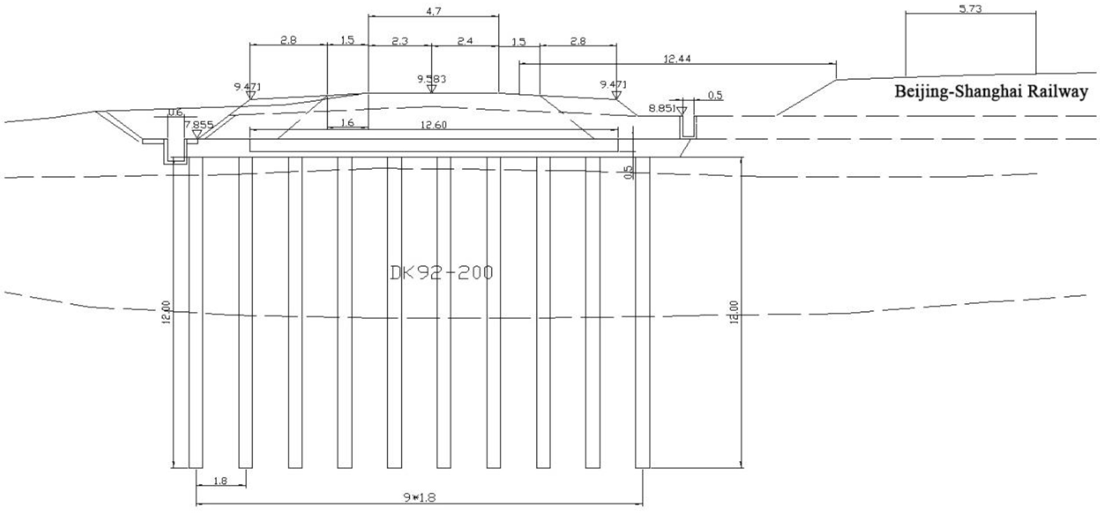
2. Project Overview
3. On-Site Power Test
3.1. Test Content
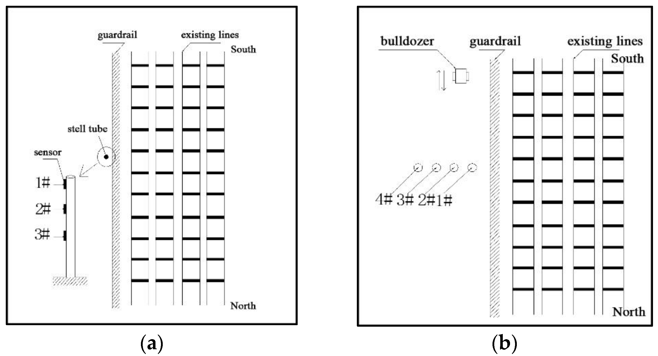
3.2. Test Methods
4. Analysis of Test Results
4.1. Vibration Frequency
4.1.1. Subgrade Natural Frequency
4.1.2. Train Excitation Frequency
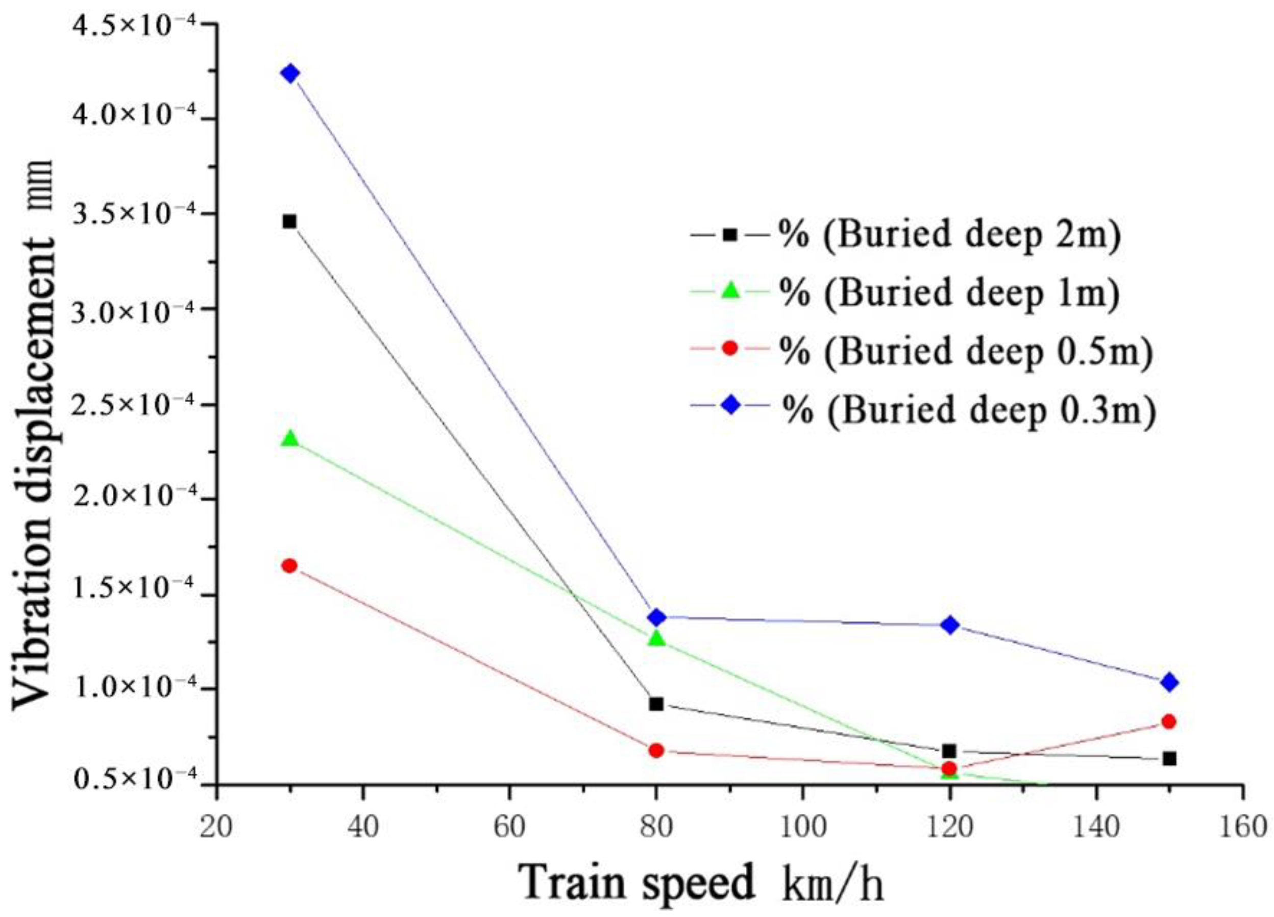
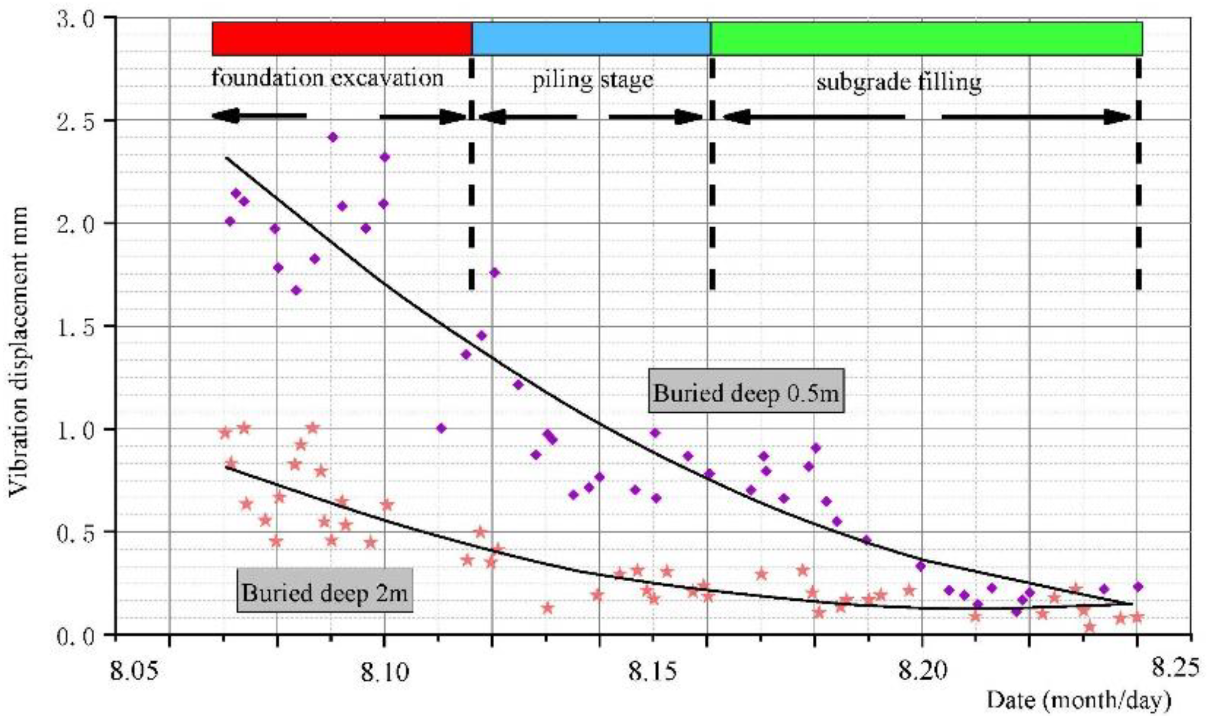
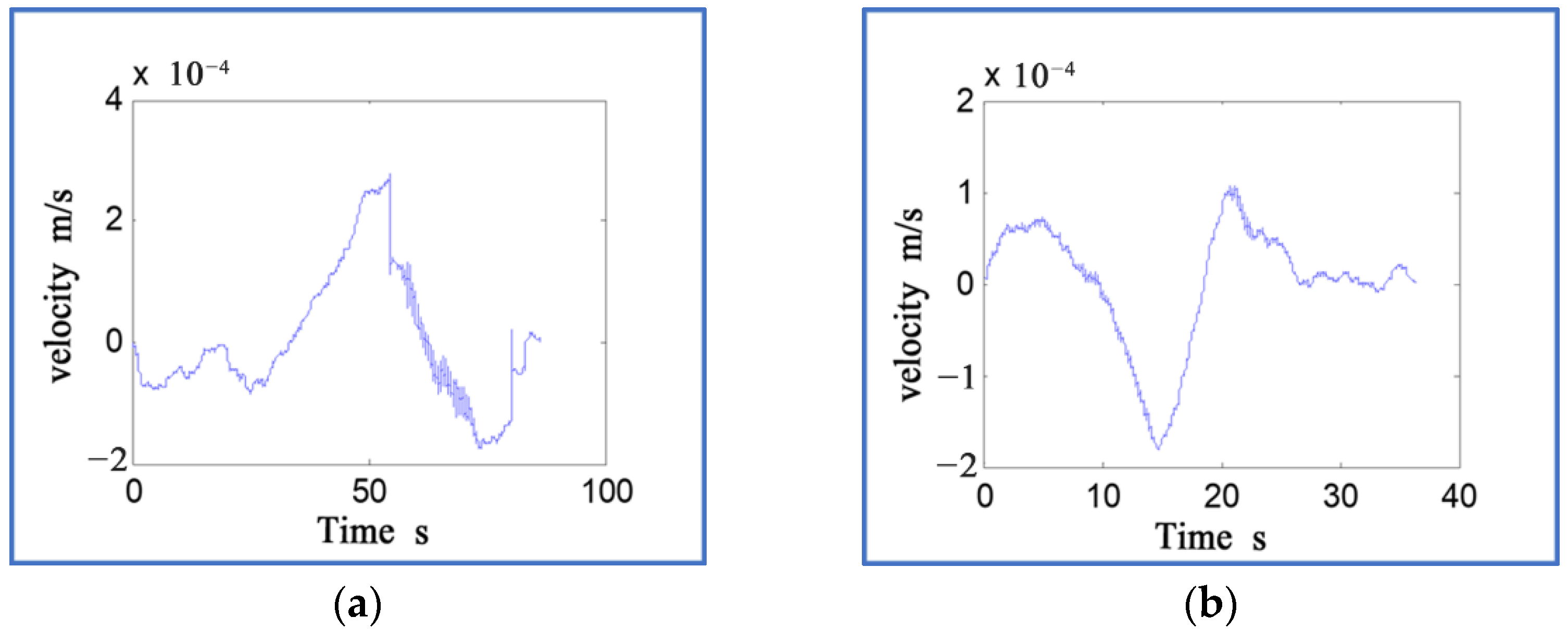
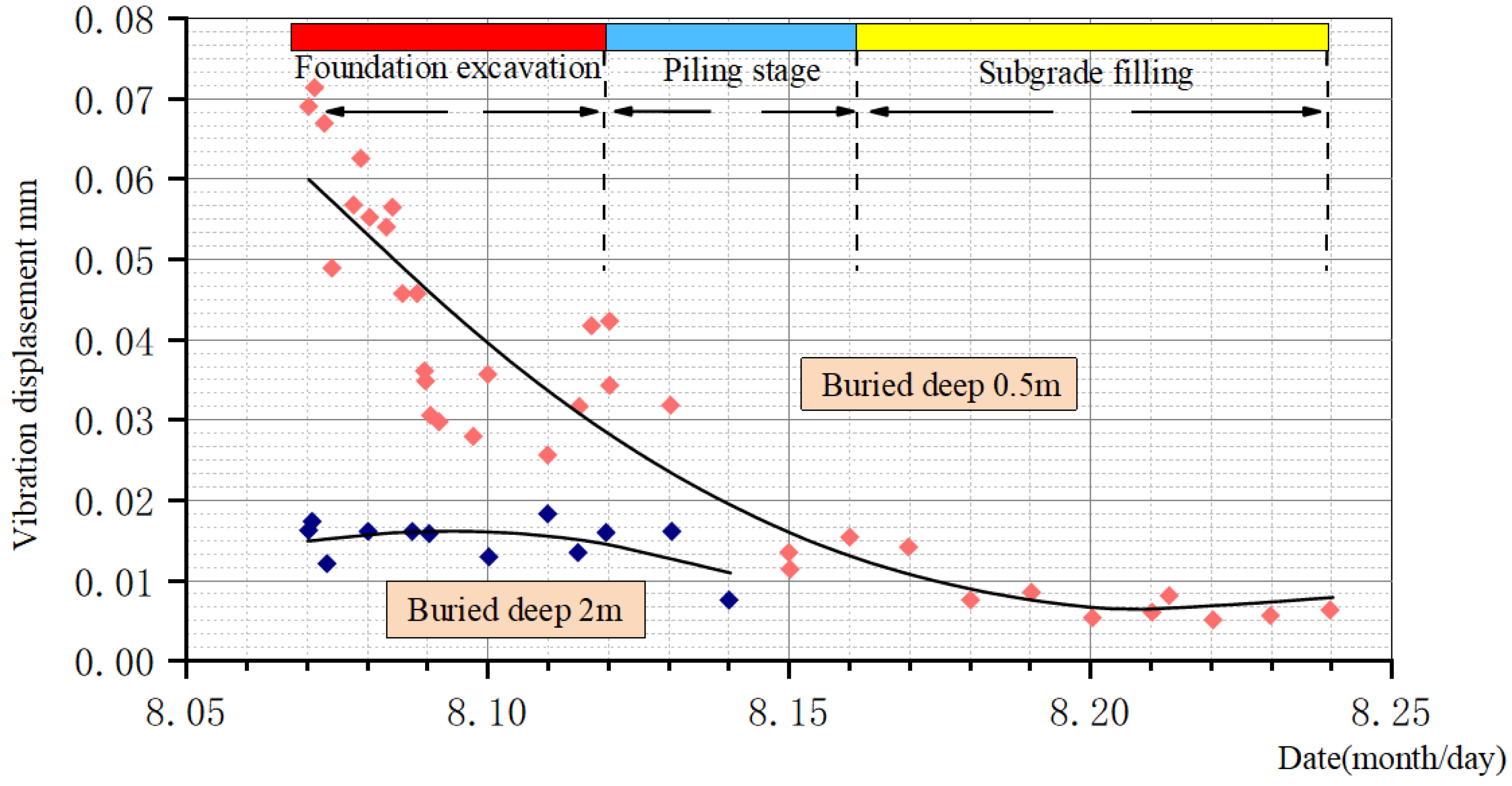
4.2. Vibration Displacement
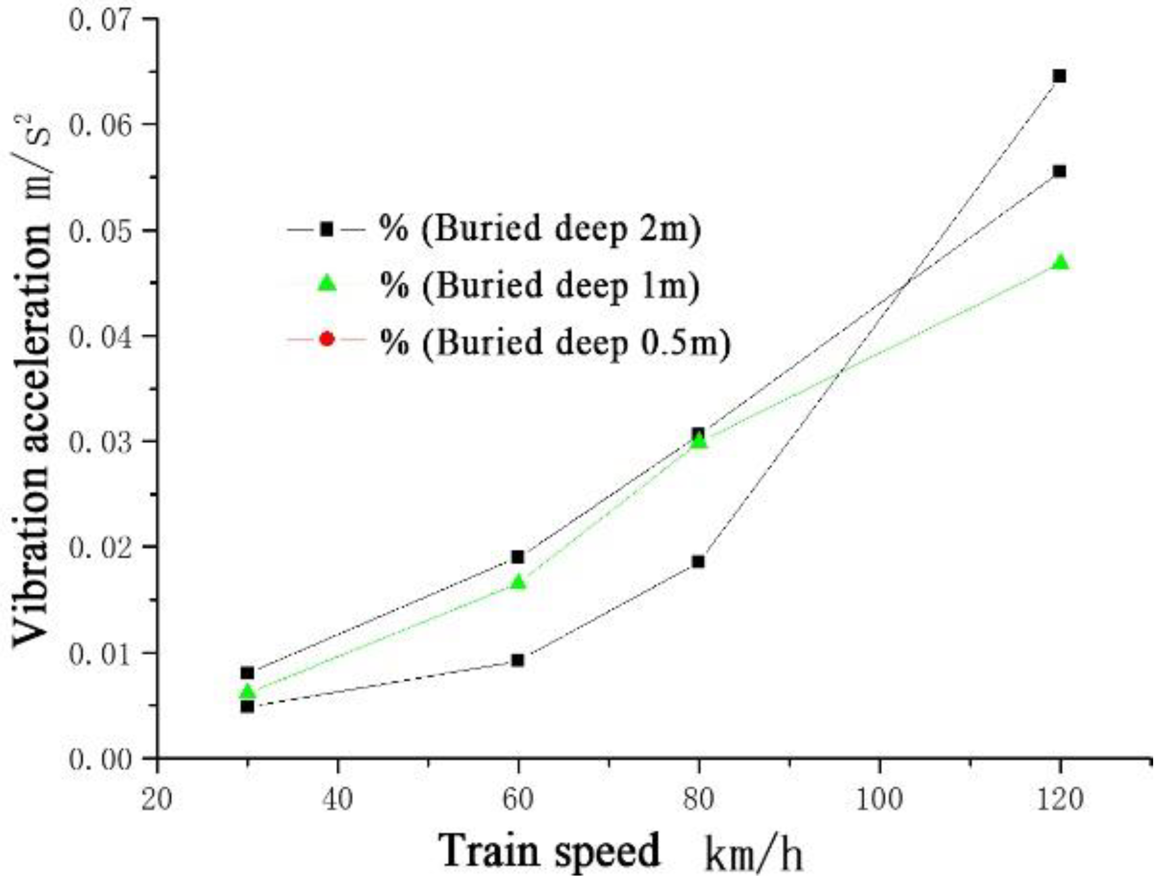
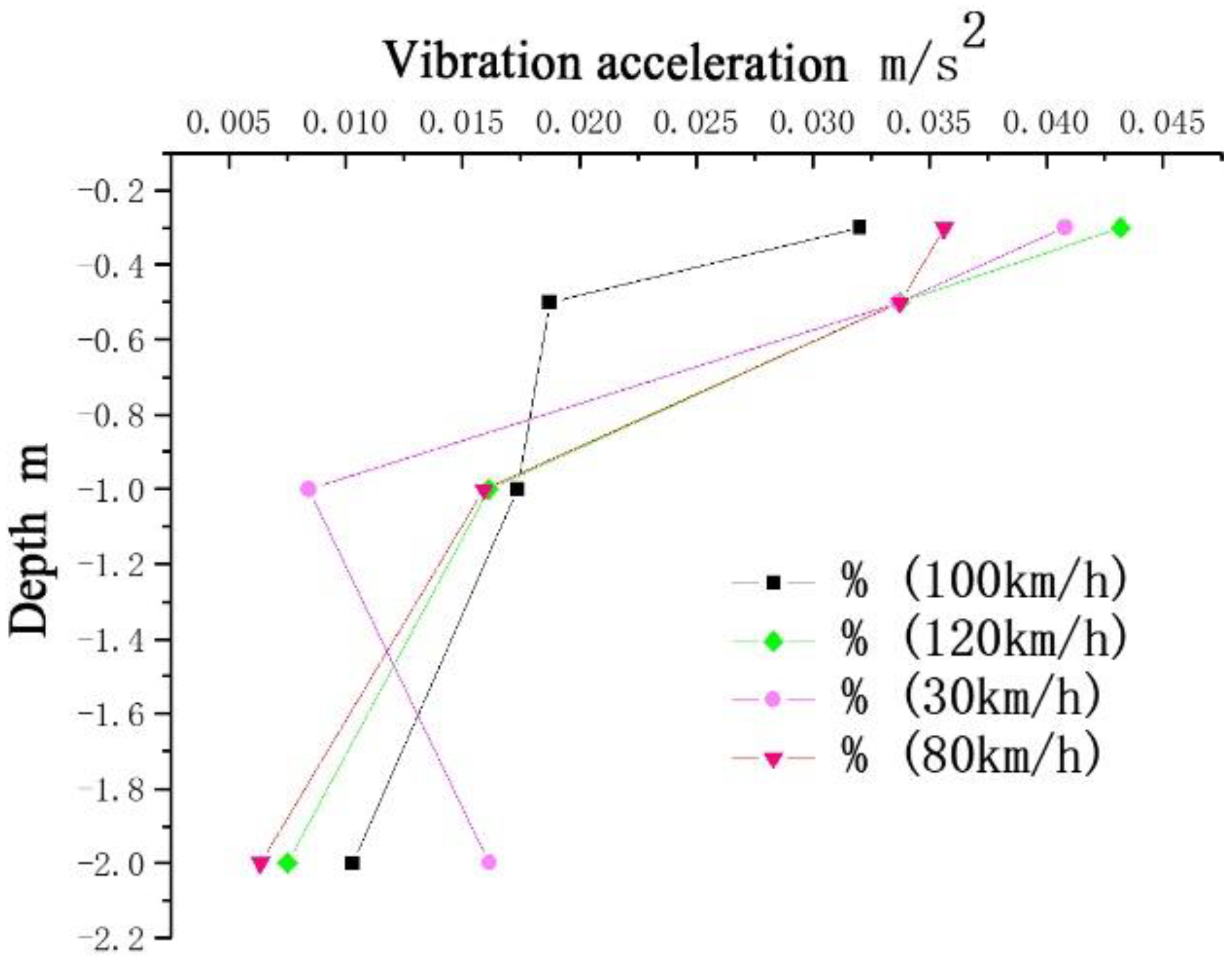
4.3. Vibration Acceleration
5. Test-Based Construction Safety Measures
5.1. Subgrade Excavation Stage
5.1.1. Excavation Roadbed Slope Protection
5.1.2. Reasonable Opening of Skylights and Determination of Construction Blocking Time
5.2. Engineering Measures in the Piling Stage
- (1)
- By setting up stress release holes on the side adjacent to the existing line, the soil-squeezing effect of the pipe pile construction can be effectively released, and the continuous transfer of soil to the existing line side can be blocked to ensure the safety of the existing line.
- (2)
- Using static pressure construction instead of dynamic piling.
- (3)
- The jumping sequence is adopted to form the pile, and the purdah is formed as soon as possible.
6. Conclusions
- (1)
- A set of dynamic performance testing methods for railway subgrade in operation are proposed to obtain the dynamic performance indicators of the subgrade, such as vibration displacement, vibration frequency, and vibration acceleration of the existing subgrade under the influence of construction.
- (2)
- During testing, the peak value of the vibration response parameter in the subgrade excavation stage was the largest, which was the most dangerous stage of the subgrade dynamic stability. Subgrade vibration acceleration as a common index of structural dynamics has similar standards to follow, which can directly reflect the dynamic performance of the test body, and vibration displacement can be used as a dynamic deformation condition to evaluate the dynamic stability of the subgrade. Therefore, it is suggested that these two parameters be used as the dynamic stability control index of the existing roadbed under the influence of excavation.
- (3)
- During testing, the excitation frequency of the train to the subgrade is close to the natural frequency of the railway subgrade, and the possible resonance will lead to the aggravation of the subgrade vibration. This situation mainly occurs in the foundation excavation stage, and it was found that it is affected by the changes in the foundation stress field and displacement field. Based on this, it is suggested that the engineering construction department take preventative measures, such as strengthening the slope and speeding up the construction.
- (4)
- Dynamic testing provides a forecast and an early warning for the stability of the subgrade slope, and supplies data support for the protection of the subgrade slope and the reasonable opening of skylights. The piling construction technology is optimized from the perspective of subgrade dynamic stability, and the adverse effects, such as the extrusion and vibration of the adjacent existing line foundation, are eliminated by setting up stress relief holes, static pressure pipe piles, and jumping construction.
Author Contributions
Funding
Institutional Review Board Statement
Informed Consent Statement
Data Availability Statement
Conflicts of Interest
References
- Huo, J.; Wang, B.; Zhou, S. Safety analysis of the foundation reinforcement scheme for subway shield tunnels passing through intercity railways. China Railw. Sci. 2011, 32, 71–77. [Google Scholar]
- Xiong, Z. Horizontal displacement monitoring and reinforcement of a complex plane foundation pit supporting structure. Geotech. Mech. 2009, 30, 5. [Google Scholar]
- Yang, L. Dynamic Prediction of Foundation Pit Support Displacement and Safety Monitoring. Chin. J. Civ. Eng. 1999, 32, 5. [Google Scholar]
- Zhang, C.; Zhang, D.; Luo, J.; Wang, M.; Wu, J. Remote monitoring system in the construction of tunnels under subway stations under existing lines. Geotech. Mech. 2009, 30, 1861–1867. [Google Scholar]
- Wang, T.; Luo, Q.; Li, Z.; Zhang, W.; Chen, W.; Wang, L. System safety assessment with efficient probabilistic stability analysis of engineered slopes along a new rail line. Bull. Eng. Geol. Environ. 2022, 81, 68. [Google Scholar] [CrossRef]
- Xu, L. Research on Construction Safety and Settlement Monitoring Technology of Shanghai-Nanjing Intercity Railway; Central South University: Changsha, China, 2010. [Google Scholar]
- Liang, B.; Sun, C. Analysis of double peak phenomenon in dynamic response of high-speed railway subgrade. Chin. J. Civ. Eng. 2006, 39, 117–126. [Google Scholar]
- Zhan, Y.; Jiang, G. Field test research on dynamic response of subgrade with ballastless track pile-slab structure on Suiyu Line. Rock Soil Mech. 2009, 30, 832–839. [Google Scholar]
- Liu, J.; Xiao, J. Experimental Study on the Stability of Railroad Silt Subgrade with Increasing Train Speed. J. Geotech. Geoenvironm. Eng. 2009, 136, 833–841. [Google Scholar] [CrossRef]
- Wang, J.-J.; Chai, H.-J.; Hu, Y.-X.; Zhang, L.-J. Mechanism of dynamic instability for riverside subgrade. In Proceedings of the First International Conference on Transportation Engineering, Chengdu, China, 22–24 July 2007; American Society of Civil Engineerings: Chengdu, China, 2007; Volume 2, pp. 1933–1939. [Google Scholar]
- Ye, Y.-S. Dynamic response characteristics of high-speed railway subgrade. J. Railw. Constr. 2015, 55, 7–12. [Google Scholar]
- Han, Y.-K. Study on the dynamic response of high-speed railway subgrade. J. Constr. Technol. 2016, 45, 116–118+123. [Google Scholar]
- Bi, Q.-C.; Wang, T.; Zhang, M.X. Numerical analysis of dynamic response of heavy-duty railway subgrade. J. Hebei Inst. Civ. Eng. Archit. 2018, 36, 6–10. [Google Scholar]
- Ye, Y.; Yang, C. Dynamic stability analysis of soft soil subgrade under train load. In Proceedings of the 8th Soil Mechanics and Geotechnical Engineering Academic Conference of China Civil Engineering Society, Nanjing, China, 1 October 1999. [Google Scholar]
- Mao, Y. Ground vibration characteristics and attenuation caused by transportation vehicles. J. Build. Struct. 1987, 01, 67–77. [Google Scholar]
- Nie, Z.; Li, L.; Liu, B.; Ruan, B. Base vibration test analysis of Qinshen passenger dedicated line. Chin. J. Rock Mech. Eng. 2005, 24, 1067–1074. [Google Scholar]
- Wang, Q.-Y. Load analysis of ballastless track subgrade packing power test of high-speed railway. J. Railw. Stand. Des. 2018, 62, 6–11. [Google Scholar] [CrossRef]
- Nie, R.-S. Development and application of rail-subgrade dynamic test system. J. Chin. Soc. Railw. 2016, 38, 96–101. [Google Scholar]
- Jiang, Q.; Tang, Z.; Tang, Z. Dynamic test analysis of subgrade under different vehicle speeds. Subgrade Eng. 2009, 3, 127–132. [Google Scholar]
- Yang, X.; Gao, Y.; Liu, Z. On the detection of existing railway line bases. Chin. J. Rock Mech. Eng. 2003, 22, 2363–2367. [Google Scholar]
- Bi, X.; Zhou, S. The influence of train vibration load on the deformation of the existing station adjacent to the deep foundation pit. J. Tongji Univ. 2004, 32, 1559–1604. [Google Scholar]
- Hai, M.; Sun, Y.; Wang, B. Research on the impact of deep foundation pit excavation on adjacent subway stations. J. East China Jiaotong Univ. 2009, 26, 7–11. [Google Scholar]
- Xiang, J.; He, D.; Zeng, J. Analysis of vibration response of different types of ballastless tracks under the action of high-speed trains. Chin. J. Mech. Eng. 2010, 46, 29–38. [Google Scholar] [CrossRef]
- Qu, C.; Wang, Y.; Wei, L. Field test and analysis of subgrade vibration of Wuhan-Guangzhou high-speed railway. Rock Soil Mech. 2012, 33, 1451–1458. [Google Scholar]
- Cao, Y.; Zhao, M. Monitoring and analysis of the impact of near-area blasting on bridge vibration. Blasting 2008, 25, 82–85. [Google Scholar]


| Equipment Name | Quantity |
|---|---|
| Donghua DH-5935 dynamic signal test and analysis system | 1 |
| DH-5935 solid state acceleration shock pickup | 4 |
| imc16 channel dynamic signal tester | 1 |
| imc accelerometer | 6 |
| 891-Ⅱ type vibration sensor (horizontal, vertical) | 6 |
| RDP displacement sensor | 5 |
| Laptop | 1 |
| Desktop PC | 1 |
| Train Speed km/h | Buried Deep (m) | Content Test | Numeric Value m/s2 |
|---|---|---|---|
| 30 | 2 | Vibration acceleration | 0.01029 |
| 1 | 0.01736 | ||
| 0.5 | 0.01874 | ||
| 0.3 | 0.03202 | ||
| 120 | 0.5 | 0.03375 |
| Particle Velocity/mm·s−1 | Vibration Effect |
|---|---|
| <1 | Hard to feel |
| 1 | Humans can feel weak vibrations |
| 5 | Makes people feel uncomfortable, vibrate |
| 10 | Disturbing, with obvious vibration |
| 33 | Gives a strong sense of vibration |
| 50 | Safe vibration limit of general civil residential buildings |
| 100 | Safe vibration limit of reinforced concrete structure and tunnel support structure |
| 140 | Cracks in rock medium and expansion of old cracks |
| 190 | General civil buildings are severely cracked and damaged |
| 300 | Vibration and shedding of rock in unsupported tunnel |
| 600 | New cracks in rock |
Publisher’s Note: MDPI stays neutral with regard to jurisdictional claims in published maps and institutional affiliations. |
© 2022 by the authors. Licensee MDPI, Basel, Switzerland. This article is an open access article distributed under the terms and conditions of the Creative Commons Attribution (CC BY) license (https://creativecommons.org/licenses/by/4.0/).
Share and Cite
Zuo, S.; Li, T.; Li, J.; Liu, P.; Cui, X. Research on Dynamic Response and Construction Safety Countermeasures of an Adjacent Existing Line Foundation under the Influence of a New Railway Line. Coatings 2022, 12, 641. https://doi.org/10.3390/coatings12050641
Zuo S, Li T, Li J, Liu P, Cui X. Research on Dynamic Response and Construction Safety Countermeasures of an Adjacent Existing Line Foundation under the Influence of a New Railway Line. Coatings. 2022; 12(5):641. https://doi.org/10.3390/coatings12050641
Chicago/Turabian StyleZuo, Shen, Tianyu Li, Jin Li, Peng Liu, and Xinzhuang Cui. 2022. "Research on Dynamic Response and Construction Safety Countermeasures of an Adjacent Existing Line Foundation under the Influence of a New Railway Line" Coatings 12, no. 5: 641. https://doi.org/10.3390/coatings12050641
APA StyleZuo, S., Li, T., Li, J., Liu, P., & Cui, X. (2022). Research on Dynamic Response and Construction Safety Countermeasures of an Adjacent Existing Line Foundation under the Influence of a New Railway Line. Coatings, 12(5), 641. https://doi.org/10.3390/coatings12050641