Article

Prediction of Mechanical Properties of Thin-Walled Bar with Open Cross-Section under Restrained Torsion

1
School of Mechanical Engineering, Hunan University of Science and Technology, Xiangtan 411201, China
2
Hunan Provincial Key Laboratory of Health Maintenance for Mechanical Equipment, Hunan University of Science and Technology, Xiangtan 411201, China
*
Author to whom correspondence should be addressed.
Coatings 2022, 12(5), 562; https://doi.org/10.3390/coatings12050562
Submission received: 5 March 2022 / Revised: 6 April 2022 / Accepted: 18 April 2022 / Published: 21 April 2022

Abstract

:
Thin-walled bars with an open cross-section are widely used in mechanical structures where weight and size control are particularly required. Thus, this paper attempts to propose a theoretical model for predicting the mechanical properties of a thin-walled bar with an open cross-section under restrained torsion. Firstly, a theoretical model with predictions of shear stress, buckling normal stress, and secondary shear stress of the thin-walled bar with open cross-section under the condition of restrained torsion was developed based on torsion theory. Then, physical test and finite element modeling data were employed to validate the theoretical predictions. The results indicate that the theoretical predictions show good agreements with data of finite element modeling and experiments. Therefore, the proposed theoretical model could be used for the prediction of the mechanical response of a thin-walled bar with an open annular section under restrained torsion.

1. Introduction

Thin-walled bars with an open cross-section are widely used in the design of structural components in various fields of engineering, including mechanical, civil, marine, and aerospace structures [1,2,3]. Compared with the components with a closed thin-walled cross-section, an open cross-section subjected to torque loads is generally prone to larger warping stress and a larger angle of twist [4]. When the torque is the same, the maximum shear stress on the thin-walled bars with an open cross-section will be several times or even dozens of times of that in the closed cross-section condition, while the torsional deformation is extremely higher than that in the closed condition. Due to the large elastic deformation of the thin-walled bar with an open cross-section, there is a need for its application in some places with special requirements for space and weight.
In engineering calculations, the open thin-walled annular section torsionbar is usually regarded as an elongated rectangular section developed by the approximate method, and its shear stress distribution is similar to that of the elongated rectangular section [5]. Saint-Venant’s torsion theory providesa classical explanation of the free torsion of the bar, but in the actual application of the torsion bar, it is basically constrained torsion, and pure, free torsion seldom appears [6]. The comprehensive theory of Vlasov has focused on effectively calculating the mechanical properties of thin-walled bars under a combination of torsion and bending [7,8]. However, there is a lack of theoretical research on the evaluation of the mechanical properties of the thin-walled bar with an open cross-section [9,10,11]. Therefore, the purpose of the current study is to propose a theoretical model for predicting the mechanical properties of the thin-walled bar with an open cross-section under restrained torsion.

2. Theoretical Analysis in Free Torsion

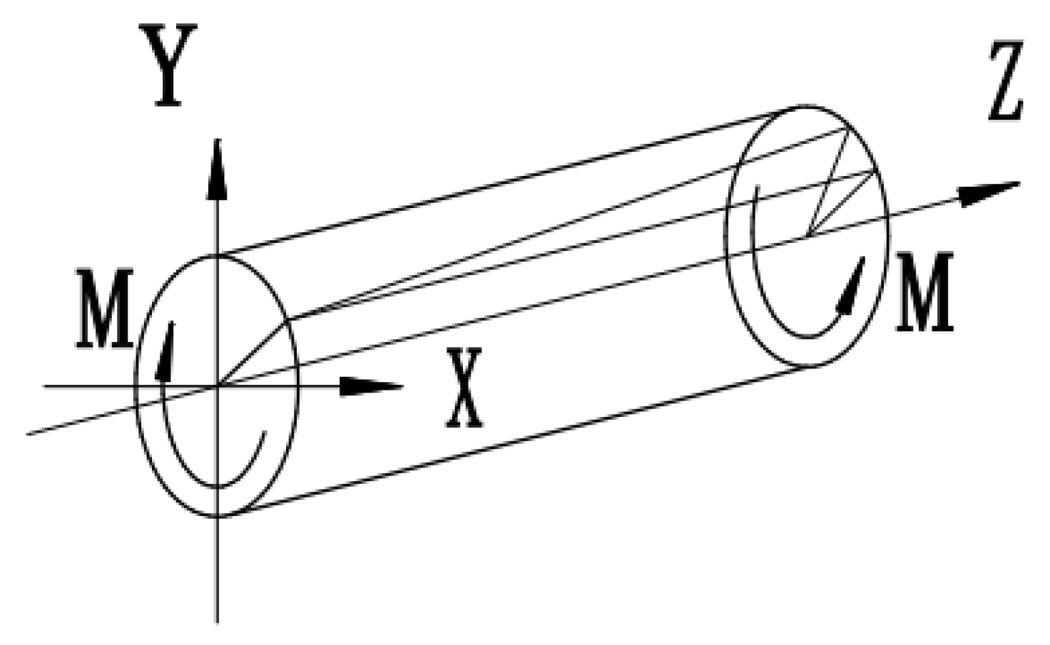
2.1. Saint-Venant’s Fundamental Equation

According to Saint-Venant’s torsion theory, no matter where the torsion axis passes through the cross-section, it has no essential effect on the warp of the torsion bar. Therefore, it is assumed that the torsion axis of the bar is consistent with that of the bar when the bar is twisted, and the cross-section of the bar always remains in the original plane before and after the torsion [12].
When the bar of equal sections is torsional under the action of a pair of equal size and opposite direction (as shown in Figure 1), according to the free torsion of Saint-Venant’s theory, except for shear stress (torsional stress) τ z x and τ z y , all other stresses on the cross-section are zero, namely:
σ x = σ y = σ z = τ z x = 0
From the above equation, the equilibrium differential equation can be obtained:
{ τ z x z = 0 τ z y z = 0 τ z x x + τ z y y = 0
Introduce a Prandtl stress function, ψ ( x , y ) , independent of z, so as to obtain:
{ τ z x = ψ y τ z y = ψ x
Let the torsion angle (torsion rate) of the bar along the unit length of the z-axis be θ , and the free torsion equation of the bar, ψ ( x , y ) , is expressed as:
2 ψ = 2 ψ x 2 + 2 ψ y 2 = 2 G θ
where G is the shear modulus of the material. The stress function, ψ ( x , y ) , on the boundary of the section is constant, and if the section is a simply connected region, the stress function on the boundary is:
ψ s ( x , y ) = 0
Let the free torsional moment of inertia of the cross-section of the bar be I d , and the torque received be H, as follows:
{ M = 2 A ψ d x d y θ = H G I d

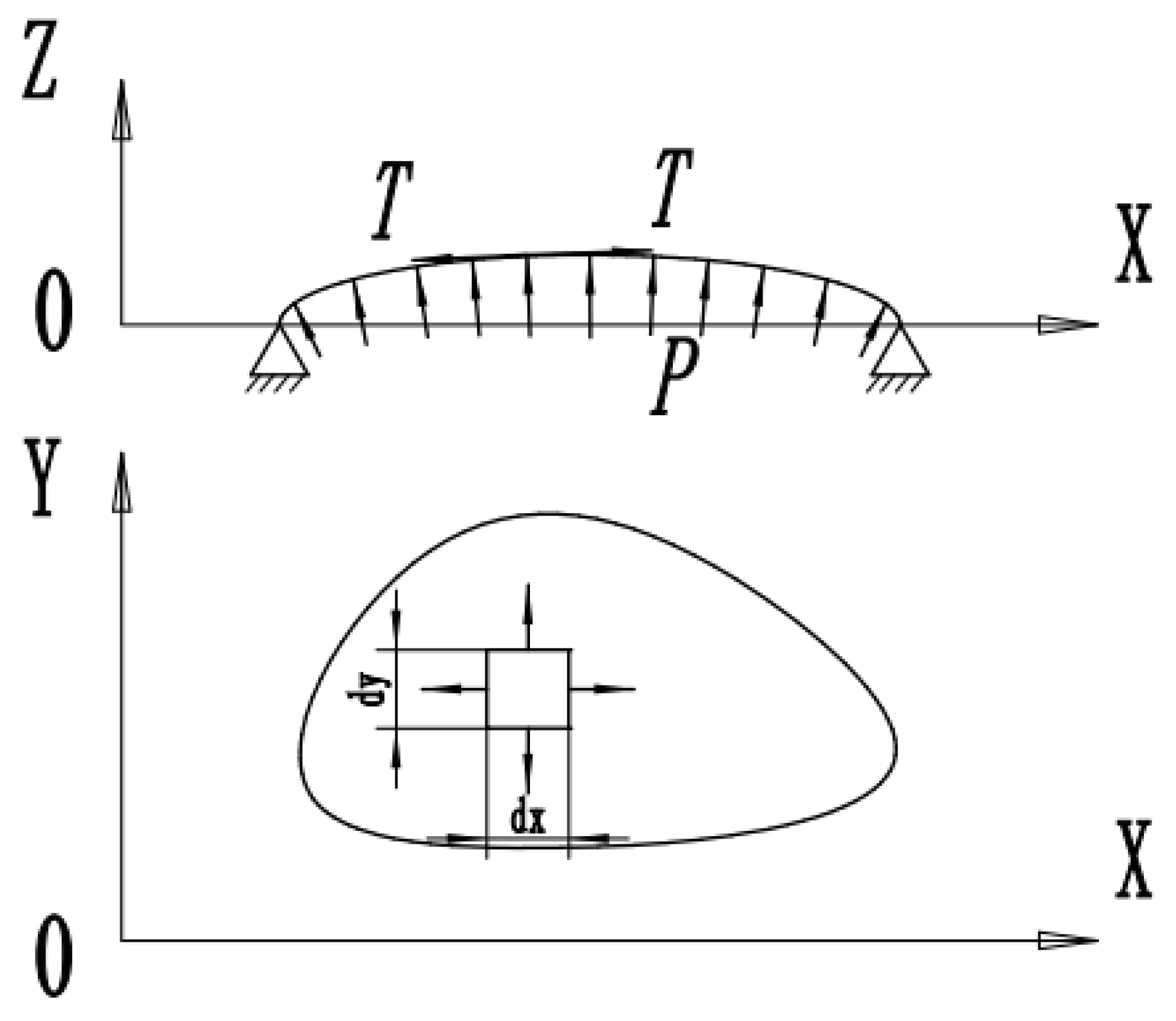
2.2. Membrane Analogy Theory in Torsion

In order to solve the torsion equation of the bar in Equation (4), the torsion problem can be compared with the deflection deformation of the membrane under uniform pressure. According to the membrane analogy theory [13,14,15], the deflection function of the membrane under the action of uniform pressure is mathematically similar to the stress function of torsion of the above-mentioned bar of equal sections.
When the membrane is subjected to a small uniform pressure, p, the point on the membrane will produce tiny deflection, w, and the membrane cannot produce bending moment, torque, shear stress, and pressure, etc., but can only produce uniform membrane tension, T, as shown in Figure 2 [16].
Under uniform pressure, the membrane will bulge outward to produce a tiny deflection, w, and the differential equation of this deflection is as follows:
2 w x 2 + 2 w y 2 = 2 w = p T
The deflection of the membrane on the boundary is obviously zero, that is:
w s = 0
Twice the volume of the bulging part of the membrane is:
2 V = 2 A ψ d x d y
In comparison with Equation (4), the differential equation of torsion and the differential equation of membrane deflection (7), as well as Equations (5), (6), (8) and (9), have exactly the same mathematical form without considering the physical meaning. The corresponding relationship can be established by using the membrane to simulate the torsion of the bar [17].

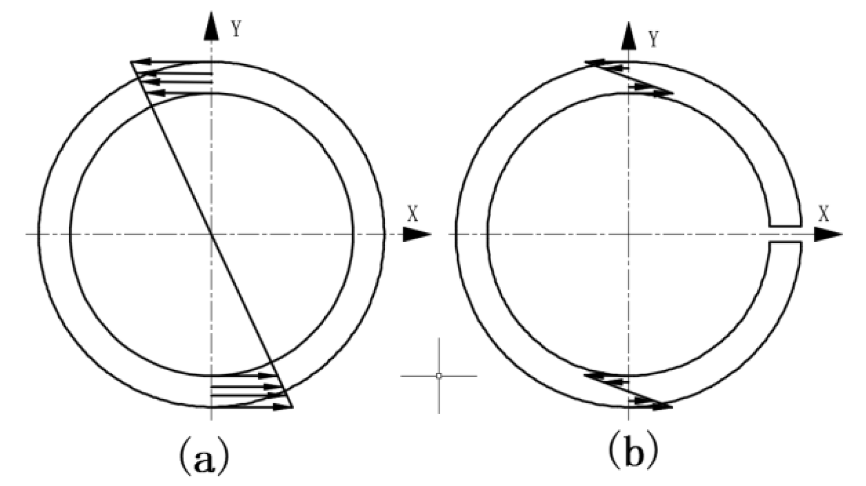
2.3. Torsional Properties of Thin-Walled Bars with Open and Closed Cross-Section

Compared with the thin-walled bars with an ordinary closed cross-section, the shear stress distribution on the thin-walled bars with an open cross-section is different. The shear stress distribution of the two is shown in Figure 3, where the median radius of the central plane contour in the figure is R, the wall thickness is δ , the left side shows the closed cross-section, and the right side is the open cross-section (Figure 3).
For the bar with the closed cross-section (as shown in Figure 3a), let the distance from any point on the section to the center of the circle be ρ , and its torsional inertia moment is:
I d = A ρ 2 d A = 2 π R 3 δ
If the torque received by the bar is H, the torsion angle (torsion rate), θ a , generated on the unit length is:
θ a = H G I = H 2 π R 3 δ G
The maximum shear stress generated on the bar is:
τ a max = H 2 π R 2 δ
For the thin-walled bar with an open cross-section (as shown in Figure 3b), it can be regarded as a bar with an elongated rectangular section with a length of 2 π R and a thickness of δ for calculation. Its torsional inertia moment is:
I d = 1 3 2 π R δ 3
Using the film analogy method, the basic differential equation of the film can be described as follows:
d 2 w d x 2 = p T
The deflection function can be obtained by two integrals:
w = p 2 T ( δ 2 4 x 2 )
The corresponding stress function is:
ψ = G θ ( δ 2 4 x 2 )
Then, it can be obtained that under the action of torque, H, the torsion angle per unit length of the bar, θ b , and the maximum shear stress on the cross-section, τ b , are:
θ b = 3 H 2 π R δ 3 G
τ b max = 3 H 2 π R δ 2
By comparing the unit length torsion angle, θ (Equations (11) and (17)), and the maximum shear stress, τ max , on the section (Equations (12) and (18)) of the thin-walled bar with an open and closed cross-section, the torsion ratio and the maximum shear stress ratio under the action of the same torque, H, are as follows:
θ b θ a = 3 ( R δ ) 2
τ b max τ a max = 3 R δ
According to Equations (19) and (20), if R / δ = 10 , then the maximum shear stress ratio and torsion ratio of the thin-walled bar with an open and closed cross-section under the action of torque, H, are 30 and 300 times, respectively. In the same case, the thin-walled bar with an open cross-section will produce a larger torsional angle. Due to this characteristic, the thin-walled bar with an open cross-section is selected for some elastic elements with special requirements.

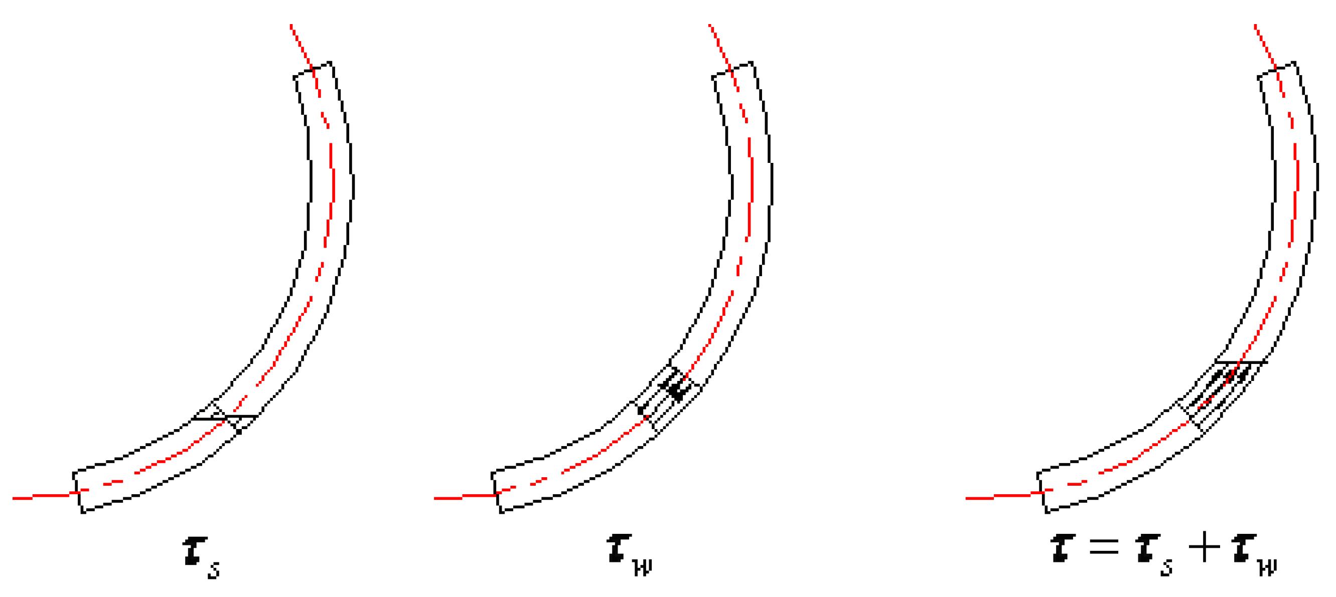
3. Theoretical Analysis in Constrained Torsion

Saint-Venant’s torsion theory is about the classic theory of torsion, but this kind of pure, free torsion in basic engineering does not exist. When the torsion bar and the cross-section of the longitudinal buckling are constrained, the constrained torsion examples abound in engineering, and the concrete stress distribution is mostly fixed at one end, on the other side of sliding support restrained torsion [18].

3.1. Differential Equation of Constrained Torsion in Thin-Walled Bar with Open Cross-Section

For free torsion, since the end of the bar is completely free and can warp freely along the z-axis, only the torsion shear stress, τ s , will be generated in the cross-section. When the restrained torsion occurs at the bar, due to the restriction of the restrained torsion on the warping displacement in the z-axis direction, the warping normal stress, σ w , and the corresponding warping shear stress, τ w , will be generated, as shown in Figure 4. The corresponding generalized force double torque, B w , and variable torque, M w , will be generated on the whole torsion bar [19]. When torsional restraint is applied, the total shear stress, τ , generated at a point on the cross-section of the bar is the sum of the torsional shear stress, τ s , and buckling shear stress, τ w , at that point [20,21]:
τ = τ s + τ w
The total torque, L, of restrained torsion is also the sum of free torque, H, and variable torque, M w :
L = H + M w
In order to calculate the stress and strain of the thin-walled bar with an open cross-section under restrained torsion, it is assumed that: (1) under the condition of small deformation, the outer contour of the bar section remains rigid in the section, but deformation can occur in the vertical section, and (2) there is a middle plane of the bar without shear strain. According to the above assumption, the buckling normal stress, M ( z , s ) , on section z of the bar is:
σ w = E 1 θ ( z ) w ( s ) + E 1 u 0 ( z )
where, E 1 = E / ( 1 μ 2 ) is the converted elastic modulus, E is the elastic modulus, μ is Poisson’s ratio, θ z is the derivative of the torsion rate, θ z , of section z with respect to the longitudinal coordinate z, ω s is the fan area of the point M ( z , s ) on section z, and u 0 ( z ) is the derivative of the longitudinal warpage displacement, u 0 ( z ) , of the point M ( z , s ) on section z with respect to the longitudinal coordinate z.
In order to solve the buckling normal stress of Equation (23), the main fan coordinate system of the section can be established according to the geometric characteristics of the main fan of the section of the bar. For the thin-walled bar with an open cross-section (as shown in Figure 5), the zero of the section’s main fan is the intersection point, M 0 , between the y-axis and the middle line of the torus, and the pole of the main fan is point A in Figure 5. The curve coordinate, M ( s ) , of the point is S = α R , and the fan area is:
w ( s ) = 0 s ρ ( s ) d s = R 2 ( 2 sin α α )
The main fan inertia moment of the open cross-section about the fan pole is:
I w = A w 2 d A = π π [ R 2 ( 2 sin α α ) ] 2 δ R d α = 2 δ R 5 ( 1 3 π 3 2 π )
The corresponding static moment of the main fan is:
S w ( s ) = π α w δ R d α = π α R 2 ( 2 sin α α ) δ R d α = 1 2 δ R 3 [ 4 ( cos α + 1 ) + ( α 2 π 2 ) ]
When the main fan coordinates are used, the buckling normal stress of Equation (23) is simplified as:
σ w = E 1 θ ( z ) w ( s )
According to the above buckling normal stress, σ w , the buckling shear stress, τ w , can be obtained as:
τ w ( z , s ) = 1 δ 0 s δ σ w z d s + τ 0 ( z ) = 1 δ E 1 θ ( z ) S w ( s )
Through the buckling normal stress (Equation (27)) and the buckling shear stress (Equation (28)), the double torque, B w , variable torque, M w , and total cross-section torque, L, of restrained torsion can be obtained:
B ( z ) = A σ w · w d A = σ w ( z , s ) · I w w ( s ) = E 1 I w θ ( z )
M w ( z ) = A τ w · δ d w = B ( z ) = E 1 I w θ ( z )
L = M w + H = E 1 I w θ ( z ) + G I d θ
where Equation (30) is the differential equation reflecting the relationship between the external torque, L, of the bar restrained torsion and the bar torsion angle θ .

3.2. Initial Parameter Method for Constrained Torsion Differential Equations

In order to solve the differential Equation (31), take its derivative with respect to z again, and obtain:
m ( z ) = d L d z = E 1 I w d 4 θ ( z ) d z 4 G I d d 2 θ ( z ) d z 2
where E 1 I w is referred to as section constraint torsional stiffness and G I d is referred to as free torsional stiffness.
Equation (32) is a fourth-order differential equation with constant coefficients, whose general homogeneous solution is:
θ = C 1 + C 2 z + C 3 s h ( k z ) + C 4 c h ( k z )
Let K = G I d E 1 I w , C 1 , C 2 , C 3 , and C 4 are undetermined coefficients, and the first three derivatives of Equation (33) are as follows:
{ θ = C 2 + C 3 k c h ( k z ) + C 4 k s h ( k z ) θ = C 3 k 2 s h ( k z ) + C 4 k 2 c h ( k z ) θ = C 3 k 3 c h ( k z ) + C 4 k 3 s h ( k z )
In combination with the torsion angle, θ , in Equation (33), the torsion rate, θ , in Equation (34), the double torque, B w , in Equation (29), and the total torque, L, in Equation (31), the following equations are obtained:
{ θ = C 1 + C 2 z + C 3 s h ( k z ) + C 4 c h ( k z ) θ = C 2 + C 3 k c h ( k z ) + C 4 k s h ( k z ) B = E 1 I w [ C 3 k 2 s h ( k z ) + C 4 k 2 c h ( k z ) ] L = G I d [ C 2 + C 3 k c h ( k z ) + C 4 k s h ( k z ) ] E 1 I w [ C 3 k 3 c h ( k z ) + C 4 k 3 s h ( k z ) ]
The four undetermined coefficients of the above equations can be determined by the initial condition parameters of the end face boundary of the bar when it is twisted. Let one end of the bar be the origin of coordinates z = 0 , and its initial parameters are:
{ θ 0 = C 1 + C 4 θ 0 = C 2 + C 3 k B 0 = G I d C 4 L 0 = C 2 G I d
Thus, the undetermined coefficients C 1 , C 2 , C 3 , and C 4 can be obtained.
{ C 1 = θ 0 + B 0 G I d C 2 = L 0 G I d C 3 = 1 k ( θ 0 L 0 G I d ) C 4 = B 0 G I d
The undetermined coefficients C 1 , C 2 , C 3 , and C 4 of Equation (37) are substituted into Equation (35) to obtain:
{ θ = θ 0 + ( s h ( k z ) k ) · θ 0 + B 0 G I d · ( 1 s h ( k z ) ) + L 0 k G I d · ( k z s h ( k z ) ) θ = c h ( k z ) B 0 G I d · k s h ( k z ) + L 0 G I d · ( 1 c h ( k z ) ) B = G I d k · θ 0 s h ( k z ) + B 0 · c h ( k z ) + L 0 k · s h ( k z ) ] L = L 0
The above formula is expressed in matrix form as:
{ Z ( z ) } = [ P ( z ) ] { Z 0 }
where { Z ( z ) } is referred to as the state vector of constrained torsion of the thin-walled torsion bar:
{ Z ( z ) } = { θ ( z ) θ ( z ) B ( z ) G I d L ( z ) G I d } T
[ P ( z ) ] is called the influence function matrix:
[ P ( z ) ] = [ 1 s h ( k z ) k s h ( k z ) 1 z s h ( k z ) k 0 c h ( k z ) k s h ( k z ) 1 c h ( k z ) 0 s h ( k z ) k c h ( k z ) s h ( k z ) k 0 0 0 1 ]

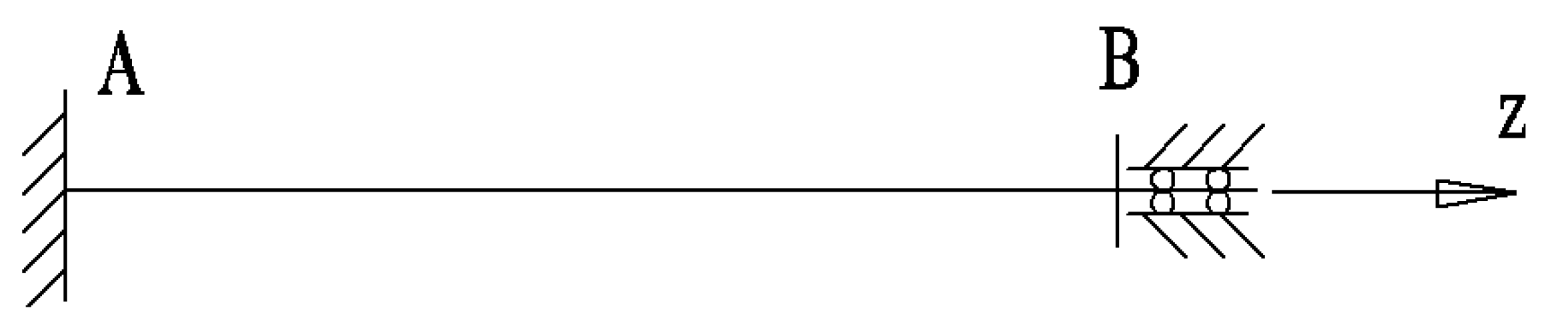
3.3. Constrained Torsion Problem of Thin-Walled Bar with Open Cross-Section

For the use of the torsional thin-walled bar with an open cross-section, one end is fixed, and the other end is the restrained torsion of the sliding support. The constraint diagram is shown in Figure 6.
The end A as shown in Figure 6 is the fixed end, which not only restricts the torsion displacement of the end face of the bar, but also restricts the longitudinal warping displacement of the end face. Both are displacement boundary conditions, which can be described as:
θ A = 0 , θ A = 0
If the origin of the z-axis is set at the end of A, the initial state vector, { Z 0 } , of restrained torsion can be expressed as:
{ Z 0 } = { 0 0 B 0 G I d L 0 G I d } T
The other end of the bar, B, is constrained by sliding support, and the longitudinal warping displacement of this end face is constrained, but it can freely rotate around the z-axis, so that the bar can produce torsion under the action of the known torque, L. Then, the boundary conditions at the B end can be described as:
θ B = 0 , L B = L
If the length of the bar is l , then the state vector of the B terminal is:
{ Z ( l ) } = { θ 0 B ( l ) G I d L G I d } T
Substitute the initial state vector at the A end and the state vector at the B end into Equation (39), and then:
{ θ 0 B ( l ) G I d L G I d } = [ 1 s h ( k z ) k s h ( k z ) 1 z s h ( k z ) k 0 c h ( k z ) k s h ( k z ) 1 c h ( k z ) 0 s h ( k z ) k c h ( k z ) s h ( k z ) k 0 0 0 1 ] { 0 0 B 0 G I d L 0 G I d }
From the second and the fourth equations, the following equation can be obtained:
L 0 = L , B 0 = L 0 k [ 1 s h ( k l ) c t h ( k l ) ]
Then, the state vector of any section of the bar with an open annular section can be obtained as follows:
{ Z ( z ) } = [ P ( z ) ] { 0 0 L k G I d [ 1 s h ( k l ) c t h ( k l ) ] L G I d }
According to the state vector of any section in Equation (48), the torsion angle and stress distribution on any section of the bar with an open annular section can be obtained under the action of external torque, L.

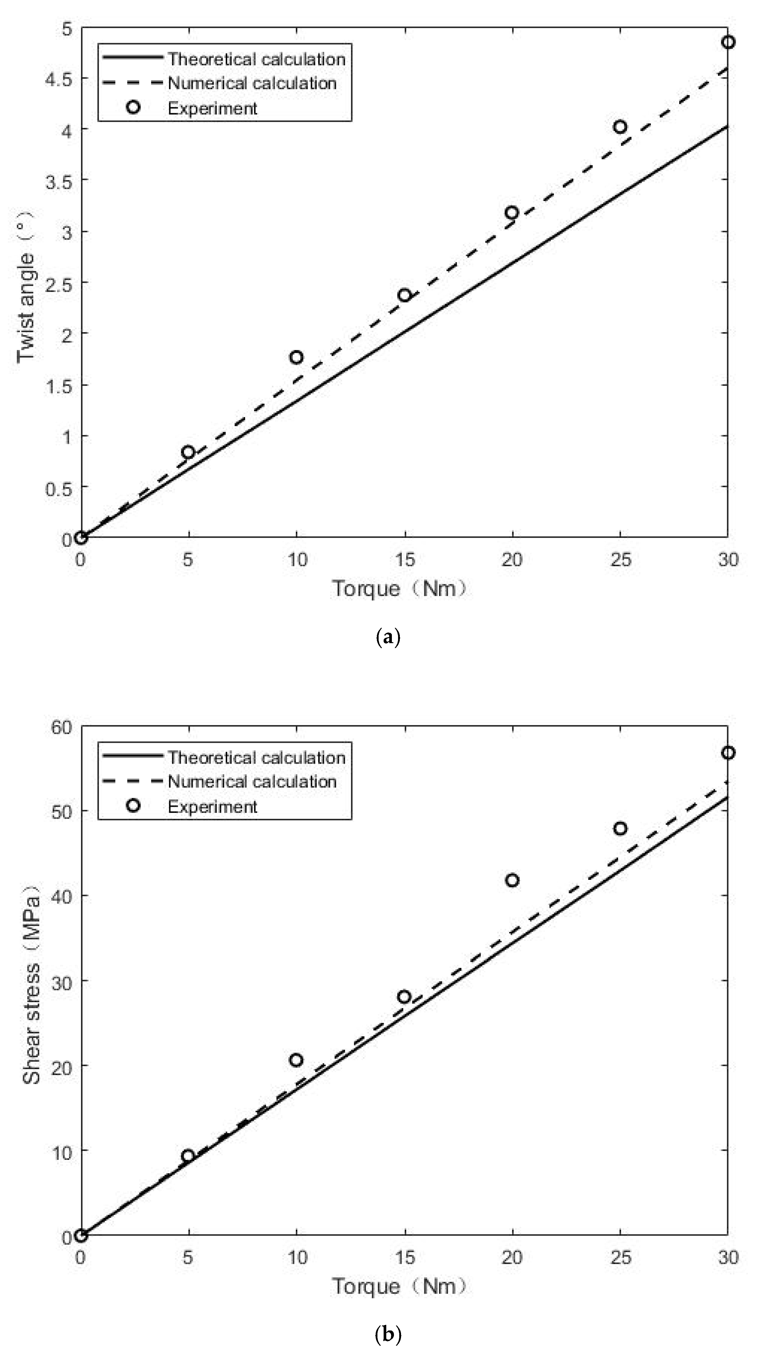
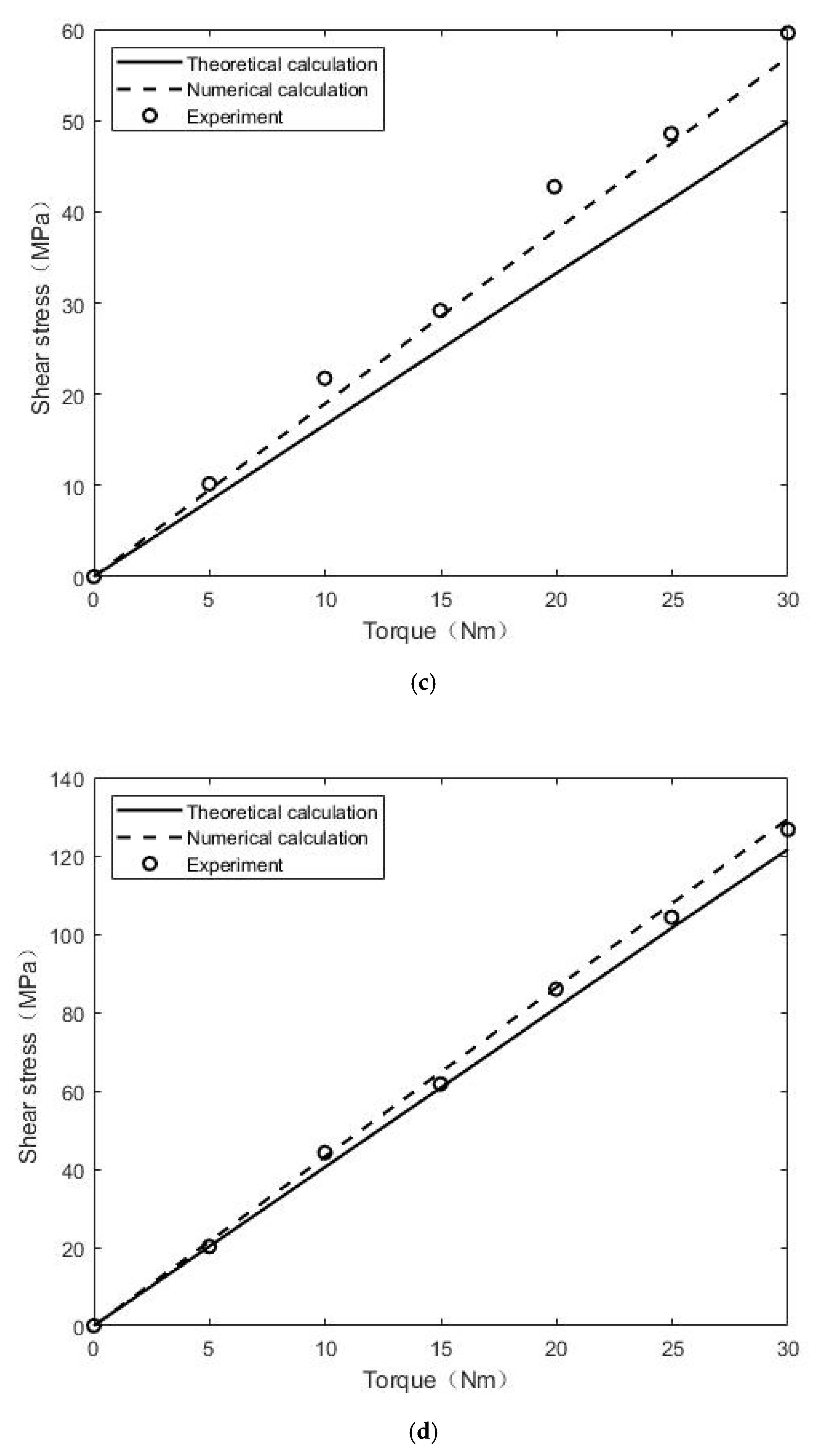
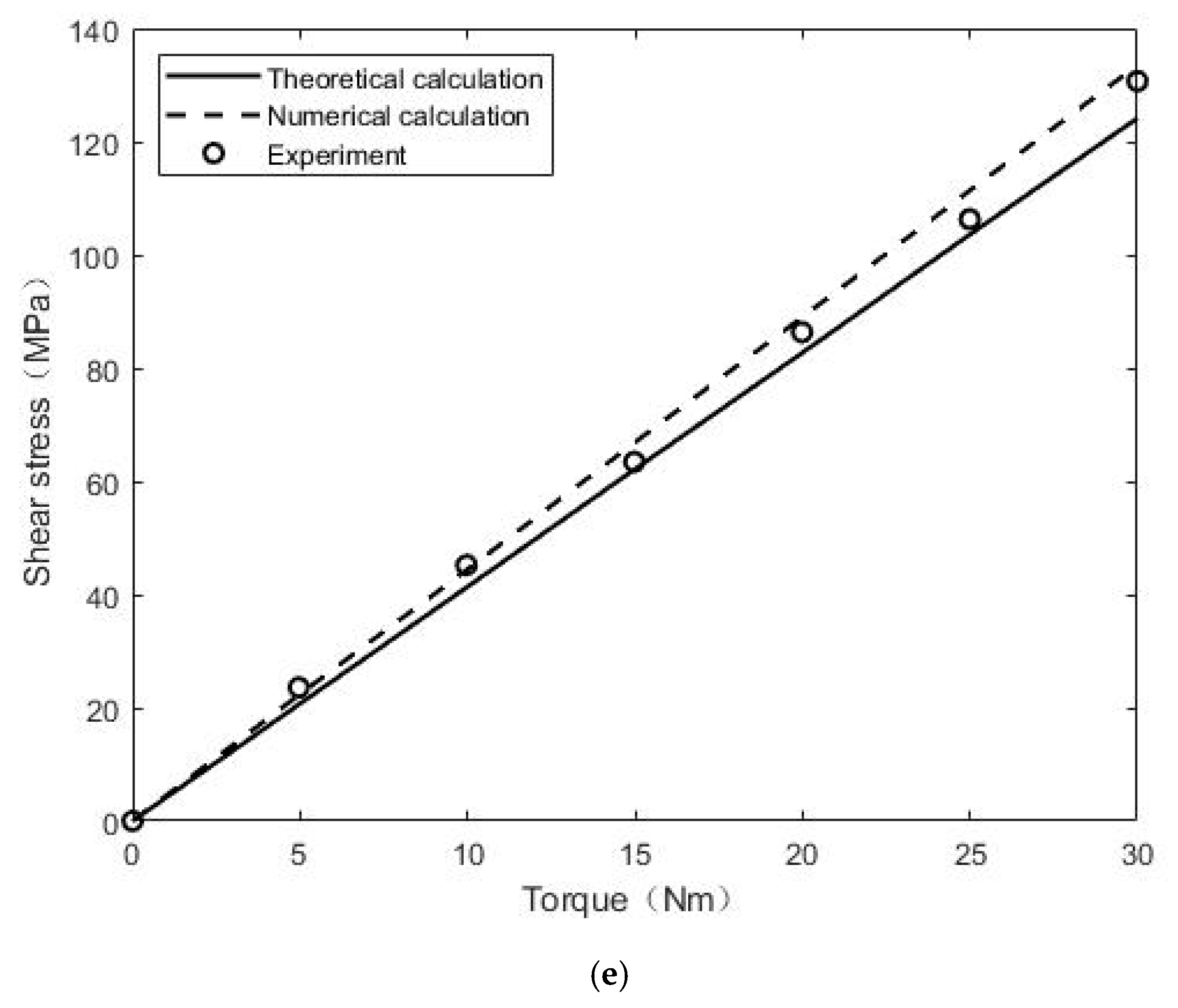
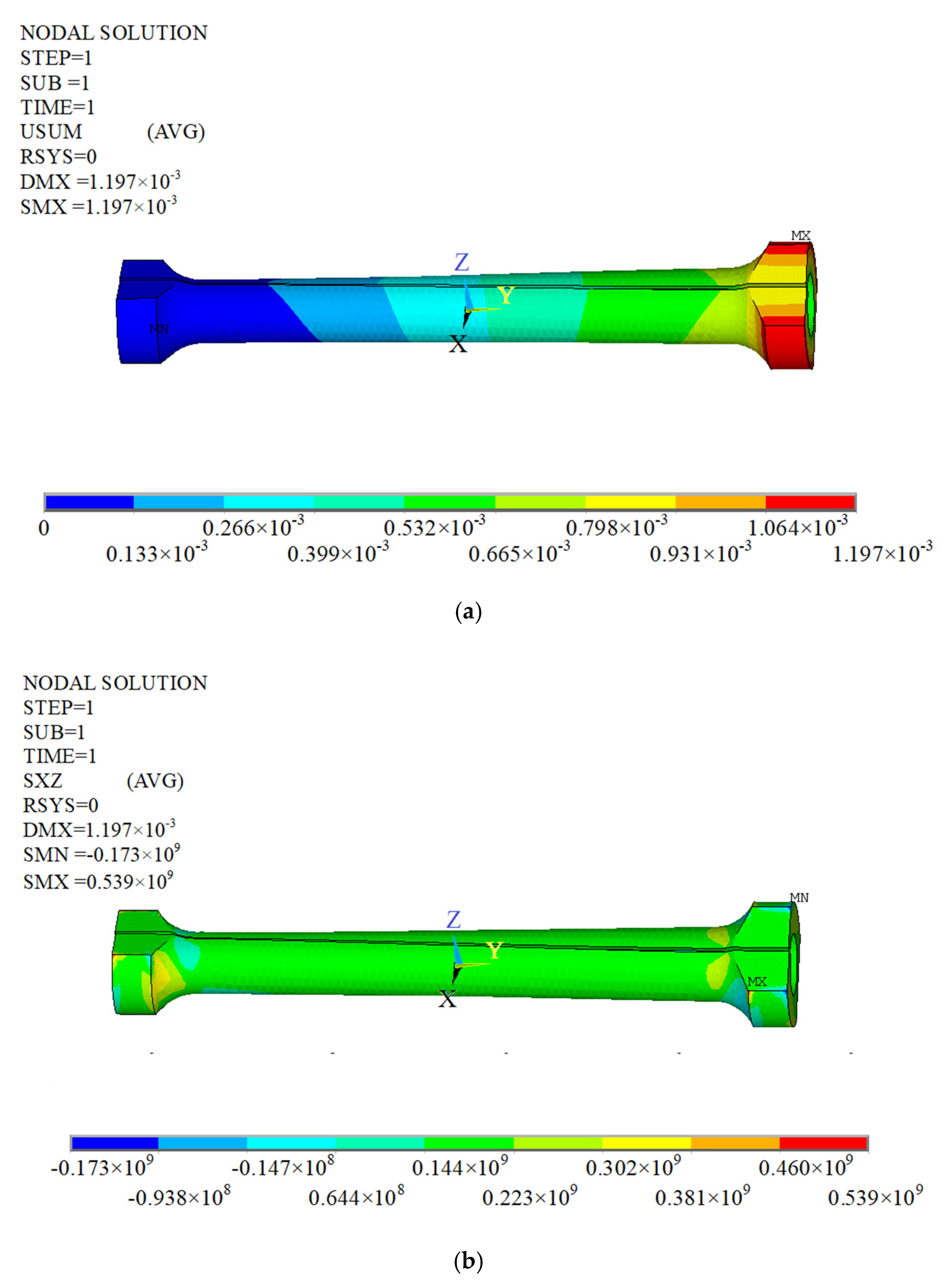
4. Experiment and Numerical Modeling Validation

In order to validate the theoretical calculation of the thin-walled bar with an open cross-section, an open torsion bar with a length of 200 mm, outer diameter of 24 mm, wall thickness of 2 mm, and opening width of 2 mm was designed (as shown in Figure 7). Then, five samples were manufactured using Q235 ordinary carbon structural steel for torsion tests. The torsion experiment is shown in Figure 8. The experiment used theNJ-100-b (1000 Nm) torsion testing machine (Qing Shan Testing Machine Co., Ltd., Ningxia, China), where torsion torque can be obtained through the torsion testing machine and the angle of the relationship between features. In order to further study the mechanics characteristic of the torsion bar, four key nodes on the sample were selected to paste the foil-type resistive strain gauge for detecting the resistance change during the torsion process, so as to calculate the positive strain and shear strain of each measurement point. The length of the rod is set as l , and the cross-section coordinates are the main fan coordinates, as shown in Figure 5. The coordinates of the four nodes are point A ( l / 4 , 0, R), point B ( l / 4 ,   π / 2 , R), point C ( l / 2 , 0, R), and point D ( l / 2 , π / 2 , R). The load is applied at 5, 10, 15, 20, 25, and 30 Nm, step-by-step. The average value of the results of five samples was employed for analysis.
The torsional characteristics of the open torsion bar and the stress strain data of the corresponding node were obtained through experiments. In order to verify the experimental data and theoretical calculation results, numerical simulations were used for comparative analysis, where a three-dimensional finite element (FE) model of the thin-walled bar with an open cross-section was developed in ANSYS environment (Figure 9). In the FE model, tetrahedral elements (ANSYS SOLID92) were used and the material parameters for the specimen Q235 ordinary carbon structural steel (elastic modulus of 208GPa and Poisson’s ratio of 0.29) were defined. In the simulations, the boundary conditions were set in accordance with the experimental tests with necessary simplification. In particular, the node coordinate system on the cylindrical surface at both ends of the member was rotated to the normal direction of the cylindrical surface, all the degrees of freedom of the end of the bar were constrained, the radial and tangential degrees of freedom of the round face of the other end were coupled, respectively, and a pair of force couples on the coupling node was applied to the bar. The stress data of the nodes in the same position as those shown in Figure 7b were extracted from the simulations.
Through torsion test experiments and finite element numerical analysis, the mechanical properties of the thin-walled bar with an open cross-section were obtained, and the theoretical calculation results were compared, as shown in Table 1. In addition, the distribution of stress and strain of the thin-walled bar with an open cross-section can be visually observed with the help of the numerical calculation data of the finite element analysis, as shown in Figure 10.
For the torsion bar, shear failure is the main form of failure. Therefore, shear stress generated in the torsion process is the main concern in the test and numerical simulations. It can be seen from the data in [17] that the shear stress results obtained by the theoretical and numerical calculations generally showed good agreement with those of the test. In particular, the shear stress data measured at points C and D on the middle section of the bar were consistent with the calculated results, with the maximum error within 10%. However, the data measured at test points A and B on the quarter-length section of the bar show that the calculation error was relatively larger.
In addition, the stress and strain distribution of the thin-walled bar with an open cross-section (as shown in Figure 11) can be observed visually with the numerical calculation data of the finite element analysis. According to the stress–strain distribution diagram, the stress concentration causes the redistribution of stress and strain. Since the middle part of the bar is far away from the end, the result of the theoretical calculation was close to the results of the numerical calculation and the test, while the stress and strain of other sections near the end were different from the ideal results. It was also found in the experiment and numerical calculation that the radial displacement constraint of the torsion end is important. If the radial displacement is generated during the torsion of the bar, it will have a great influence on the stress and strain of the whole torsion, making the stress and strain values increase a lot. In the actual measurement, it was found that if the constraint is not reasonable, the data error will be large.

5. Conclusions

In this paper, the torsion mechanical properties of a thin-walled bar with an open cross-section were studied, and the following conclusions were drawn.
(1)
The elastic properties of the thin-walled bar with open and closed cross-sections were compared on the basis of Saint-Venant’s theory, and the special properties of the thin-walled bar with an open cross-section were determined. Compared to the closed thin-walled bar, the thin-walled bar with an open cross-section can support a larger percentage of torsion and is more appropriate for the elastic structures where large deformation is needed.
(2)
The mechanical characteristic equation of the thin-walled bar with an open cross-section was established by means of small deformation theory, which can be used for predicting the analytical solution of the torsion angle and distribution of stress for the thin-walled bar with an open cross-section under restrained torsion.
(3)
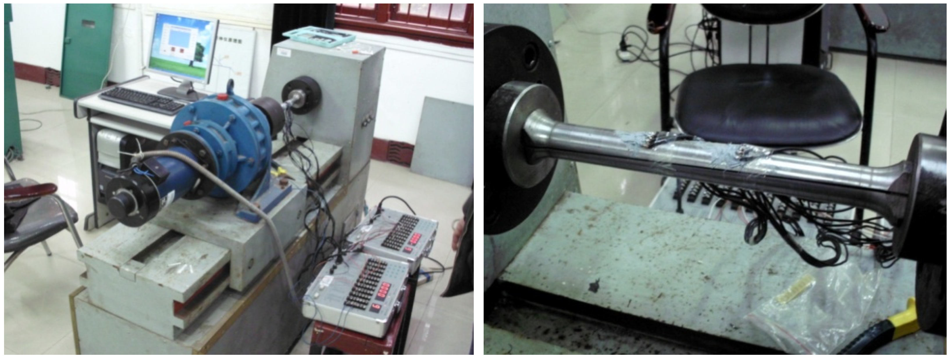
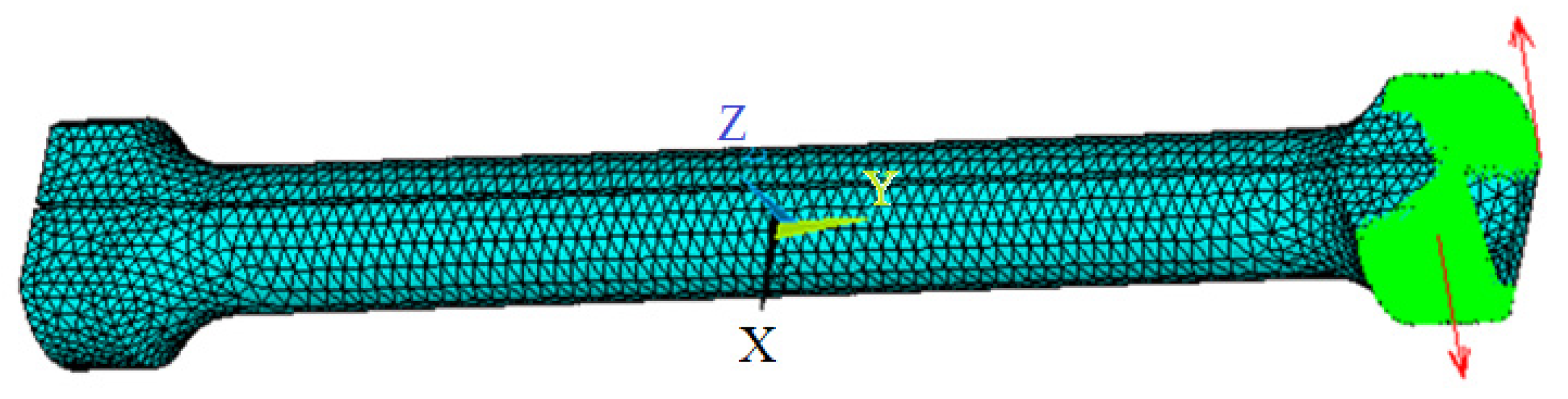
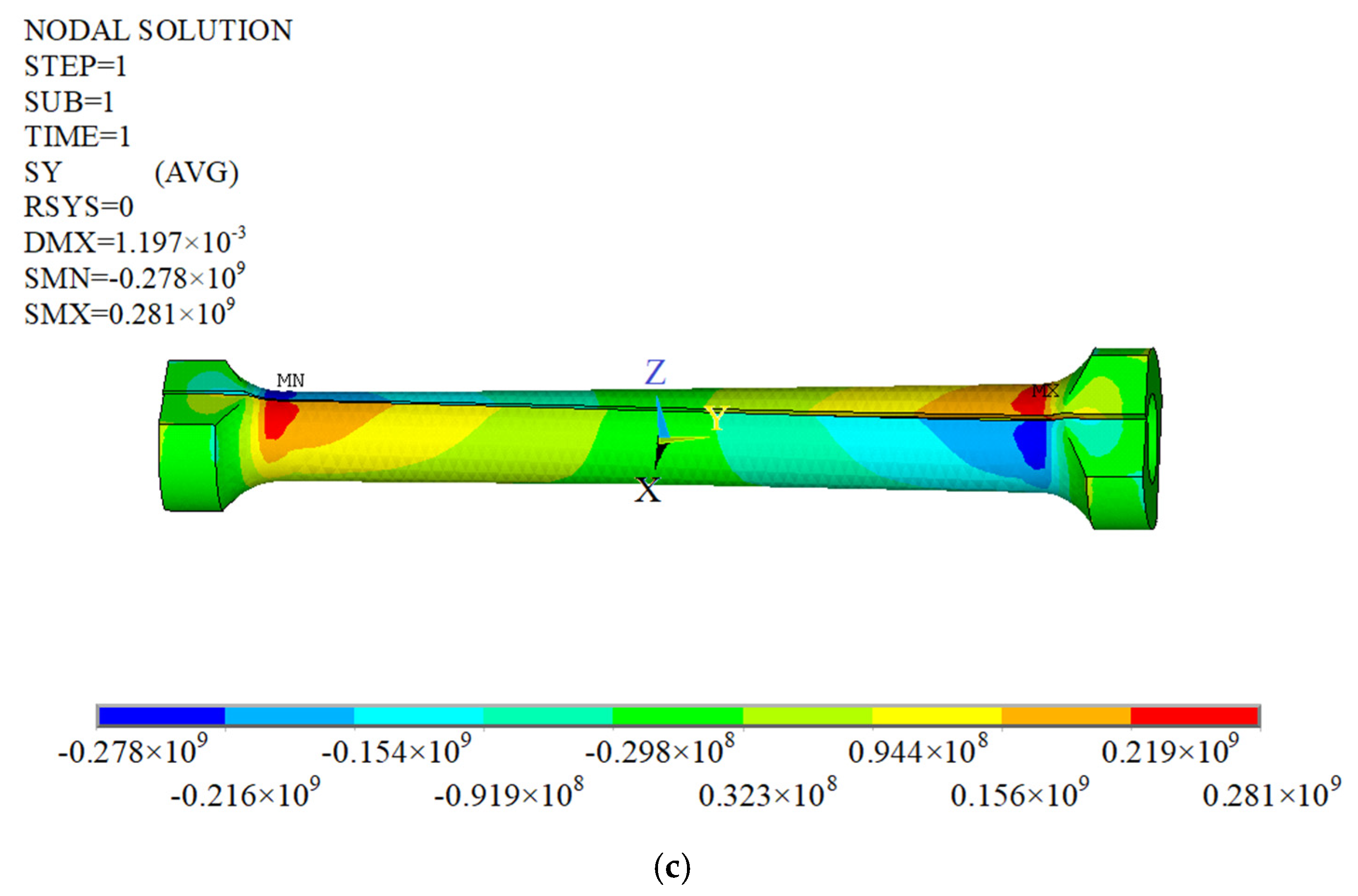
The mechanical properties of the thin-walled bar with an open cross-section were studied through an experimental test and mathematical analysis. The values of torsion angle and normal stress observed from FE simulations and experimental tests were similar to those of the theoretical solution (the error was less than 10%). The predictions of the current work can be regarded as the basic reference for the design of a thin-walled bar with an open cross-section.

Author Contributions

Simulation and data analysis, Z.C. and Z.H.; writing—original draft preparation, Z.C. and G.L.; equipment debugging and data management, Z.H.; writing—review and editing, Y.G. and G.L. All authors have read and agreed to the published version of the manuscript.

Funding

This work was supported by the Project of Natural Science Foundation of Hunan Province (Grant No. 2019JJ50155) and Scientific Research Project of Hunan Education Department (Grant No. 18C0338).

Institutional Review Board Statement

Not applicable.

Informed Consent Statement

Not applicable.

Data Availability Statement

Data sharing not applicable.

Conflicts of Interest

The authors declare no conflict of interest.

References

  1. Alam, M.I.; Kanagarajan, B.; Jana, P. Optimal design of thin-walled open cross-section column for maximum buckling load. Thin Walled Struct. 2019, 141, 423–434. [Google Scholar] [CrossRef]
  2. Sapountzakis, E.J. Torsional vibrations of composite bars by BEM. Compos. Struct. 2005, 70, 229–239. [Google Scholar] [CrossRef]
  3. Zaczynska, M.; Kazmierczyk, F. Multi-Mode Buckling Analysis of FGM Channel Section Beams. Materials 2020, 13, 2567. [Google Scholar] [CrossRef]
  4. Szychowski, A. A theoretical analysis of the local buckling in thin-walled bars with open cross-section subjected to warping torsion. Thin Walled Struct. 2014, 76, 42–55. [Google Scholar] [CrossRef]
  5. Nguyen, T.T.; Kim, N.I.; Lee, J. Analysis of thin-walled open-section beams with functionally graded materials. Compos. Struct. 2016, 138, 75–83. [Google Scholar] [CrossRef]
  6. Christiansen, S. A review of some integral equations for solving the Saint-Venant torsion problem. J. Elast. 1978, 8, 1–20. [Google Scholar] [CrossRef]
  7. Manta, D.; Gonçalves, R.; Camotim, D. Combining shell and GBT-based finite elements: Vibration and dynamic analysis. Thin Walled Struct. 2021, 167, 108187. [Google Scholar] [CrossRef]
  8. Murray, N.W.; Lau, Y.C. The behaviour of a channel cantilever under combined bending and torsional loads. Thin Walled Struct. 1983, 1, 55–74. [Google Scholar] [CrossRef]
  9. Plaut, R.H.; Moen, C.D. Lateral-torsional deformations of single-span and two-span thin-walled beams with continuous bracing. J. Constr. Steel Res. 2021, 179, 106534. [Google Scholar] [CrossRef]
  10. Plaut, R.H.; Moen, C.D. Flexural-torsional deformations of imperfect thin-walled columns with discrete bracing. Thin Walled Struct. 2020, 154, 106897. [Google Scholar] [CrossRef]
  11. Pham, C.H.; Hancock, G.J. Shear tests and design of cold-formed steel channels with central square holes. Thin Walled Struct. 2020, 149, 106650. [Google Scholar] [CrossRef]
  12. Wang, X.; Xia, P.; Masarati, P. Optimal Control of Pretwisted Rotating Thin-Walled Beams via Piezoelectrically Induced Couplings. AIAA J. 2019, 57, 1–17. [Google Scholar] [CrossRef]
  13. Yu, J.; Sun, W.; Huang, H.; Huang, Y. Study on the deformation control and microstructures of thin-walled parts repaired by laser cladding. Coatings 2020, 10, 369. [Google Scholar] [CrossRef] [Green Version]
  14. Troyani, N.; Perez, A.; Gomes, C.; Baiz, P.; Fonseca, Z.D. Selective finite element refinement in torsional problems based on the membrane analogy. Finite Elem. Anal. Des. 2009, 45, 547–554. [Google Scholar] [CrossRef]
  15. Aronov, B.; Sharir, M. On a Procedure for analyzing Saint-Venant torsional stresses by means of membrane analogy. J. Jpn. Soc. Exp. Mech. 1990, 10, 137–173. [Google Scholar] [CrossRef]
  16. Obst, M.; Kurpisz, D.; Paczos, P. The experimental and analytical investigations of torsion phenomenon of thin-walled cold formed channel beams subjected to four-point bending. Thin Walled Struct. 2016, 106, 179–186. [Google Scholar] [CrossRef]
  17. Prisekin, V.L.; Rastorguev, G.I. Bending and cramped torsion of thin-walled rods. Mech. Solids 2019, 54, 1030–1041. [Google Scholar] [CrossRef]
  18. Lanoye, E.; Dormieux, L.; Kondo, D. A micromechanical-based damage analysis of a cylindrical bar under torsion: Theoretical results, finite elements verification and application. Theor. Appl. Fract. Mech. 2014, 74, 116–125. [Google Scholar] [CrossRef]
  19. Erkmen, R.E.; Mohareb, M. Torsion analysis of thin-walled beams including shear deformation. Thin Walled Struct. 2008, 44, 1096–1108. [Google Scholar] [CrossRef]
  20. Janarthanan, B.; Mahendran, M. Behaviour and strength of unlipped channel sections under combined bending and torsion. J. Constr. Steel Res. 2021, 182, 106648. [Google Scholar] [CrossRef]
  21. Wan, H.X.; Huang, B.; Mahendran, M. Experiments and numerical modelling of cold-formed steel beams under bending and torsion. Thin Walled Struct. 2021, 161, 107424. [Google Scholar] [CrossRef]
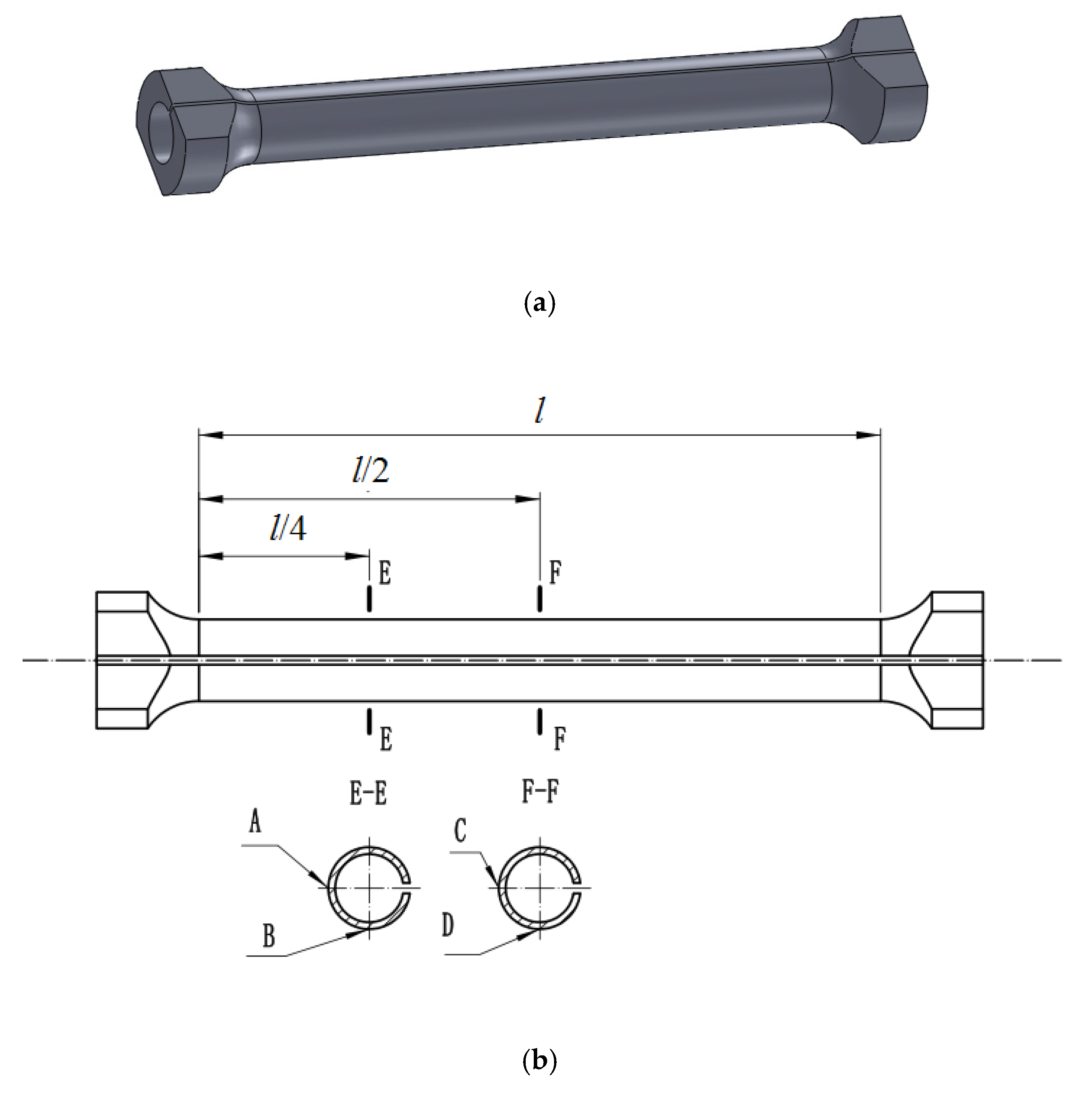
Figure 1. Torsion of bar with equal cross-section.
Coatings 12 00562 g001
Figure 2. Membrane analogy.
Coatings 12 00562 g002
Figure 3. Shear stress distribution of thin-walled bars with a (a) closed and (b) open cross-section.
Coatings 12 00562 g003
Figure 4. Constrained torsional buckling shear stress.
Coatings 12 00562 g004
Figure 5. The fan area of the open-ring section.
Coatings 12 00562 g005
Figure 6. Constraint diagram of torsional thin-walled bar with open cross-section.
Coatings 12 00562 g006
Figure 7. Torsion bar with an open annular section. (a) The 3D model of the torsion bar with an open annular section. (b) The exact measurement points of A, B, C, and D.
Coatings 12 00562 g007
Figure 8. Torsion experiment of the thin-walled bar with an open cross-section.
Coatings 12 00562 g008
Figure 9. Finite element model of torsional thin-walled bar with an open cross-section.
Coatings 12 00562 g009
Figure 10. Torsional mechanical characteristics of thin-walled bar with an open cross-section. (a) Torsional angle. (b) Shear stress at point A. (c) Shear stress at point B. (d) Shear stress at point C. (e) Shear stress at point D.
Coatings 12 00562 g010aCoatings 12 00562 g010bCoatings 12 00562 g010c
Figure 11. Stress and strain diagram of the thin-walled bar with an open cross-section under the action of 30 Nm torque. (a) Comprehensive strain of the bar. (b) Normal stress of the bar. (c) Shear stress of the bar.
Coatings 12 00562 g011aCoatings 12 00562 g011b
Table 1. Torsional mechanical characteristics of the thin-walled bar with an open cross-section.
Load
(Nm)
Angle of Rotation
(°)
Shear Stress of Point A
(Mpa)
Shear Stress of Point B
(Mpa)
Shear Stress of Point C
(Mpa)
Shear Stress of Point D
(Mpa)
Theoretical calculation50.678.318.5520.2520.58
101.3416.6117.1640.5041.25
152.0224.9225.7960.7562.07
202.6833.2234.3481.0682.65
253.3641.3642.89101.50103.57
304.0349.8351.58121.64124.14
Numerical calculation50.779.498.8221.5022.27
101.5418.9417.7643.1444.33
152.3128.4826.7164.7566.79
203.0737.9535.6686.2588.94
253.8447.4644.47107.75111.33
304.6156.9553.42129.40133.49
Experiment50.8410.179.3720.2423.59
101.7721.7420.6544.2045.22
152.3729.1728.0861.7563.45
203.1842.7441.7585.9086.34
254.0248.5747.84104.25106.30
304.8559.6656.75126.64130.69
Publisher’s Note: MDPI stays neutral with regard to jurisdictional claims in published maps and institutional affiliations.

