Article

Optimal Design and Processing Technology of 3D Printed Tibial Implants

1
School of Mechanical and Electrical Engineering, Zhoukou Normal University, Zhoukou 466000, China
2
School of Mechanical and Automotive Engineering, South China University of Technology, Guangzhou 510640, China
*
Author to whom correspondence should be addressed.
Coatings 2022, 12(5), 561; https://doi.org/10.3390/coatings12050561
Submission received: 16 March 2022 / Revised: 9 April 2022 / Accepted: 15 April 2022 / Published: 21 April 2022

Abstract

:
It is necessary to study the design method and molding techniques of selective laser melting (SLM) tibial implants to improve the success rate of knee implant surgery and the quality of life of patients. In this study, the three-dimensional (3D) reconstruction of tibial implants was completed using the reverse combined with forward methods, optimization design was carried out on the constructed tibial implant model by adopting the parametric finite element method (FEM), and the SLM device was employed for the direct manufacture of tibial implants and to study its molding techniques. The results indicated that the tibial implant model completed using reverse and forward methods combined with FEM displayed favorable modeling effects, with more homogeneous stress distribution. After optimizing the molding techniques of SLM molding tibial implants, excellent molding effects could be achieved, with high tibial implant surface finish but no buckling deformation or obvious adhering slag. Studying the above modeling and molding methods can provide important foundation for the individualized design and direct manufacture of tibial implant.

1. Introduction

With the development of human bone repair and replacement surgery, artificial joint replacement is frequently employed to alleviate patient suffering, restore the human bone function and improve the quality of life of patients [1]. However, total hip replacement often fails due to looseness caused by poor matching, excessive wear caused by improper processing or post-processing, etc., after implantation [2]. Apart from the influence of the patient’s pathological factors, the main reasons for the failure of surgery include the lack of surgical experience of doctors, the mismatch of implant shape and unsatisfactory molding process, etc. Personalized implants have been widely applied due to their good biocompatibility, excellent mechanical properties and low looseness rate after implantation [3]. Therefore, this study aimed to investigate the individualized design method of tibial implants and the selective laser melting (SLM) direct molding technique, so as to optimize the compatibility and molding quality of knee implants and to improve the service life of implants as well as the quality of life of patients.
The emergence of additive manufacturing (AM) has provided the possibility for the direct manufacture of such individualized implants. AM has utilized special software for sectioning of the three-dimensional (3D) model to obtain the cross-sectional data, which are then imported into the rapid molding device to manufacture the entity part through layer manufacturing. AM can manufacture parts of almost any geometrical shape using layer manufacturing, which is associated with the advantages of processing a single part, in limited quantity, with complicated geometric construction and compactness of the processed structure [4]. SLM is an AM based on laser melting metal powder [5,6].
In China, Song Changhui et al. [7] completed the reverse reconstruction and repair of a femoral prosthesis in the knee implant. He first carried out CT scanning of the affected site, obtained affected side data, and completed the reverse reconstruction using the Mimics software. Subsequently, the distal femoral articular surface was fitted in the Geomagic software. Finally, the curvature of the free-form surface was adjusted through the curvature grid, so that it was closer to the original distal femoral articular surface. In addition, Chen Zhenqiu and Zhang Qiuxia et al. [8] from the First Affiliated Hospital of Guangzhou University of Chinese Medicine completed the modeling of a unicondylar knee implant using the Pro/E software. The constructed model allowed for self-adaptation, which could obtain a series of satisfactory implant models through changing the input parameters according to the difference in disease site among different patients and the requirements of different surgical schemes; thus, it could attain the goal of parametric modeling of individualized implants. Wei Zhiyuan et al. [9] discussed the surgical effects and clinical significance of 3D printed personalized bone plate internal fixation in the treatment of severe tibial plateau fractures. Han Yanlong et al. [10] analyzed the impact of 3D printing-assisted total knee arthroplasty (TKA) and found that 3D printing-assisted TKA had better short-term clinical effects than conventional TKA, significantly promoted the efficiency of surgery and the accuracy of postoperative force line, and improved postoperative knee function. Moreover, V Jeevan Kumar et al. [11] completed the modeling of a human knee and investigated the changes in biomechanical properties and flexion angle of a single bone under various loading conditions. Kumbhalkar M A et al. [12] completed the 3D reconstruction of knee prosthesis through the 3D modeling software Pro/E and evaluated the stress distribution of knee prosthesis under several force loading conditions using the software of finite element analysis ansys. Abe F et al. [13] studied the influence of SLM process parameters on the molding performance of titanium alloy implants and discovered tha scanning speed had greater influence on the tensile strength of pure titanium. Calignano F et al. [14] discovered through investigating the titanium alloy bracing structure that the Taguchi structure could eliminate or reduce the buckling deformation of parts. Teo et al. [15] customized 3D-printed stainless steel proximal tibia for fractures to lock the bone plate and the guide plate with surgical screws.
Taken together, it can be suggested out that there are numerous disadvantages in the current knee implant modeling and molding methods, especially for the matching design and molding technique of knee tibial prosthesis. Therefore, this paper mainly investigated the modeling method and SLM technique of individualized tibial implants.

2. Materials and Methods

2.1. Modeling Methods

To satisfy the bearing and motor functional requirements of the tibial implant after implantation, it is required that the designed implant should possess certain intensity and stiffness. Meanwhile, the implant elasticity modulus should not be greater than the stress shielding produced by the surrounding bone tissues. The mechanical properties of the implant are not only related to its structural design, but also to its composing material that, in this case, depends on the molding process parameters and on the post-processing performed. It is an important influence factor determining whether the implant can be successfully applied. The tibial mechanical properties are shown in Table 1.
The implant was designed following the specified dimension stipulated in the GBT 228-2010 Standard of Room Temperature Tensile Test Method for Metal Material, and related property analysis was tested based on this standard. Meanwhile, the scaling test pieces with a tensile test piece diameter of 5 mm and a gauge length of 25 mm were selected according to YY 0117.3-2005 Forging and Casting CoCrMo Alloy Casting Standard of Surgical Implant Osteoarticular Prosthesis. Figure 1 shows the design dimension requirements of the tensile test piece. Figure 1: L0 was the gauge length of the tensile test piece 25 mm; Lc was the parallel length of the tensile test piece 35 mm; and L was the overall length of the tensile test piece 60 mm.

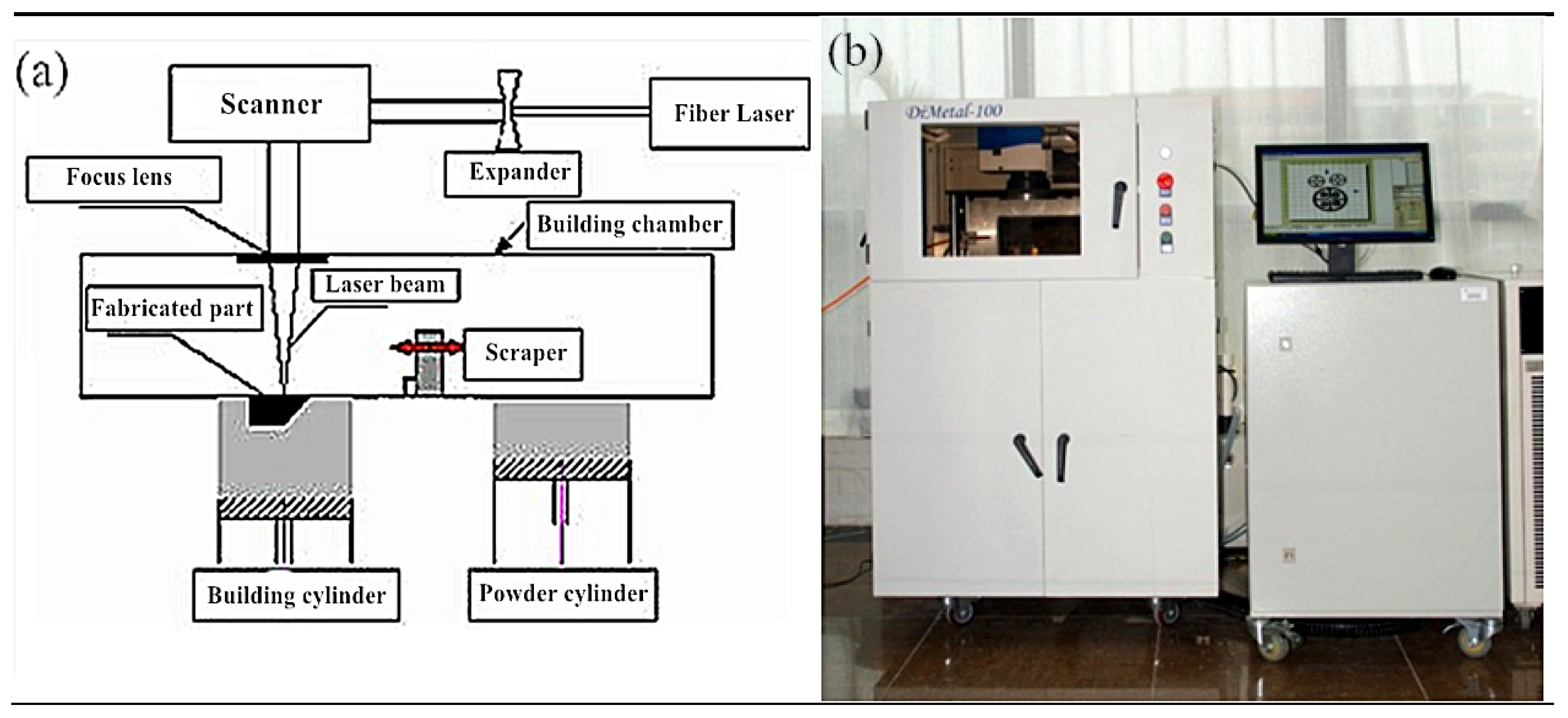
2.2. Manufacturing Method

The molding material was CoCrMo alloy metal powder (SANDVIK osprey, Neath, UK), with its composition satisfying the ASTM F1377 requirements (see Table 2). The powder was prepared in the manner of gas atomization, which was spherical, with the particle size distribution of narrow region concentrating distribution, with 90–22% and 10–28.5% µm.
The SLM device Dimetal-100 was used for processing, as shown in Figure 2. The molding parameters were as follows: using nitrogen as the shielding gas, oxygen content of below 0.03%, processing laser power of 170 W, scanning speed of 500 mm/s, scanning spacing of 80 μm, and processing layer thickness of 35 μm. The X-Y interlayer staggered scanning strategy was utilized. At least 3 test pieces were processed.

2.3. Analytical Methods

The CoCrMo alloy tensile tests were carried out using the Material Testing Machine CMT5105(MTS, Eden Prairie, MN, USA) at a tensile speed of 0.2 mm/s. The mechanical properties were compared and analyzed in accordance with the YY 0117.1 Mechanical Performance Requirements of CoCrMo Alloy Casting in Surgical Implant Osteoarticular Prosthesis. Each group of experimental sample processing contained no fewer than three pieces.

3. Results and Discussion

3.1. Reverse Reconstruction of Tibial Implant

The disease sites vary from patient to patient, which are generally the complicated geometric profile or surface. Therefore, to better match the geometry of the designed implant and of the resected bone, and with that to reduce the possibility of prosthesis loosening and improve the success rate of the implantation, the method is to obtain the disease site images from patients through medical imaging (CT or MRI) for 3D reconstruction. The precise modeling steps are shown below.
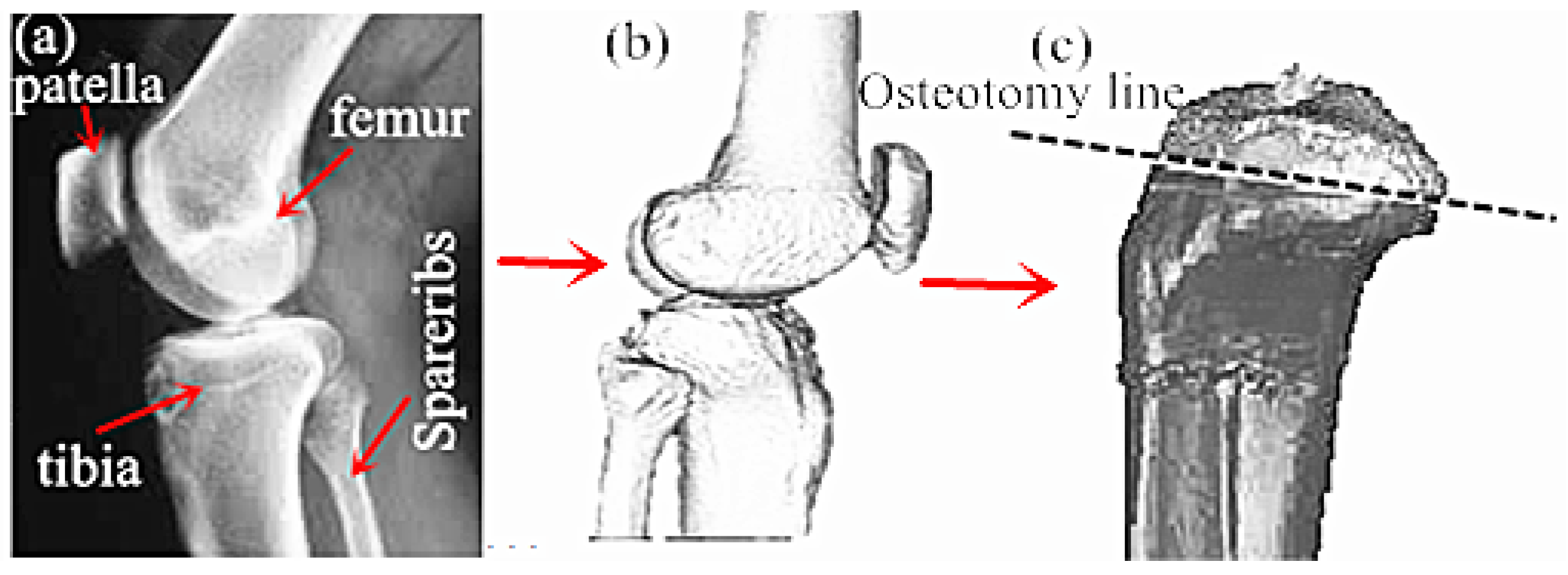
First, CT or NMR was applied to scan the disease site in patients, so as to obtain the disease site images of patients. Subsequently, the CT scanned knee disease sites were imported into the Mimics. During the importing process, the correct orientation could be selected through the right-hand button in the Change orientation window, as shown in Figure 3a.
The CT scanned images in Mimics were carried out with threshold segmentation. Then, the segmentation regions that were not connected to each other on the preliminary threshold segmentation mask were further divided into subgroups to generate the new mask. The soft tissue site was labeled as the starting point, and the ending point was labeled after the line had penetrated the bone. At this time, an intensity interface was produced, in which the prominent part represented the threshold.
The images processed after threshold segmentation were carried out with a morphological operation, and some tiny burrs on the segmentation mask border were eliminated through the opening operation (first corrosion and then swelling). Then, the thresholding images were partitioned through the region growing manner to remove the floating pixel. The Calculate 3D Modles was adopted to complete the 3D reconstruction of the CT model. Finally, the 3D reconstructed implant model was processed with smoothing and denoising, so as to obtain the optimized 3D model, as presented in Figure 3b.
The 3D reconstructed tibial implant model was imported into the Geomagic Studio for grid doctor repair, denoising, smoothing, simulation of bone cutting, and substantiation. The position of the simulated bone cutting line is shown in Figure 3c.
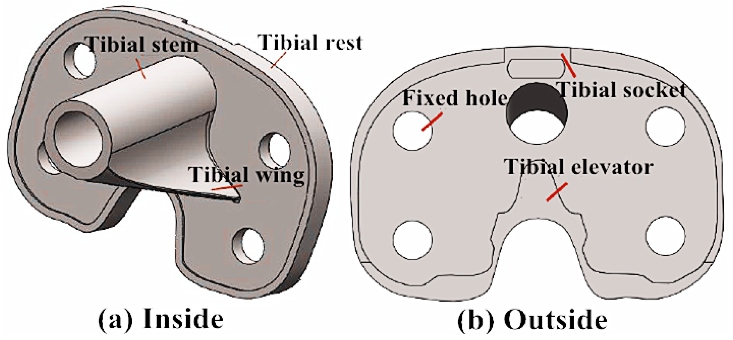
The substantialized tibial implant bone cutting model was imported into the Rhinocero software for forward design, and the corresponding tibial implant model was selected based on the bone cutting surface size and status. Meanwhile, the size and shape of the tibial stem, tibial wing, tibial convex plate, tibial groove and tibial articular surface were adjusted to adapt to the tibial articular surface and complete the forward design of the tibial implant, as displayed in Figure 4.

3.2. Simulation Optimization Design of Tibial Implant

The tibial implant optimization design (topological optimization) was mainly achieved through the finite element analysis software. The precise steps of the tibial implant optimization design were as follows: first, the implant model after parametric modeling or tailoring was imported into the finite element analysis software Autodesk Simulation Mechanical for stress analysis. The model parameters were then adjusted according to the model stress analysis results, thus optimizing the model structure, as shown below.
The 3D reconstructed tibial model was imported into the Autodesk Inventor Professiona software, and all features of the reconstructed model were read, which were delivered to the Autodesk Simulation Mechanical for finite element simulation in the manner of document delivery.
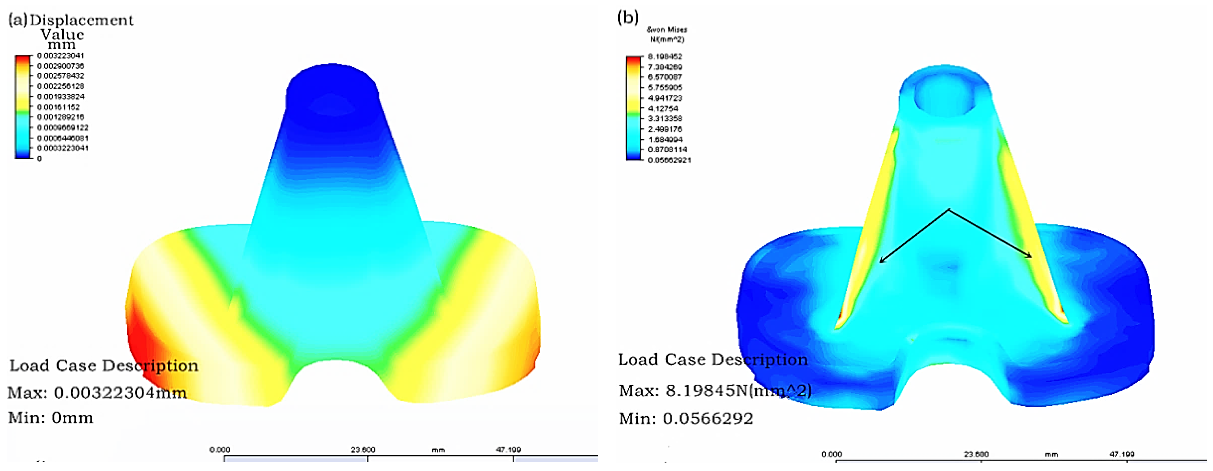
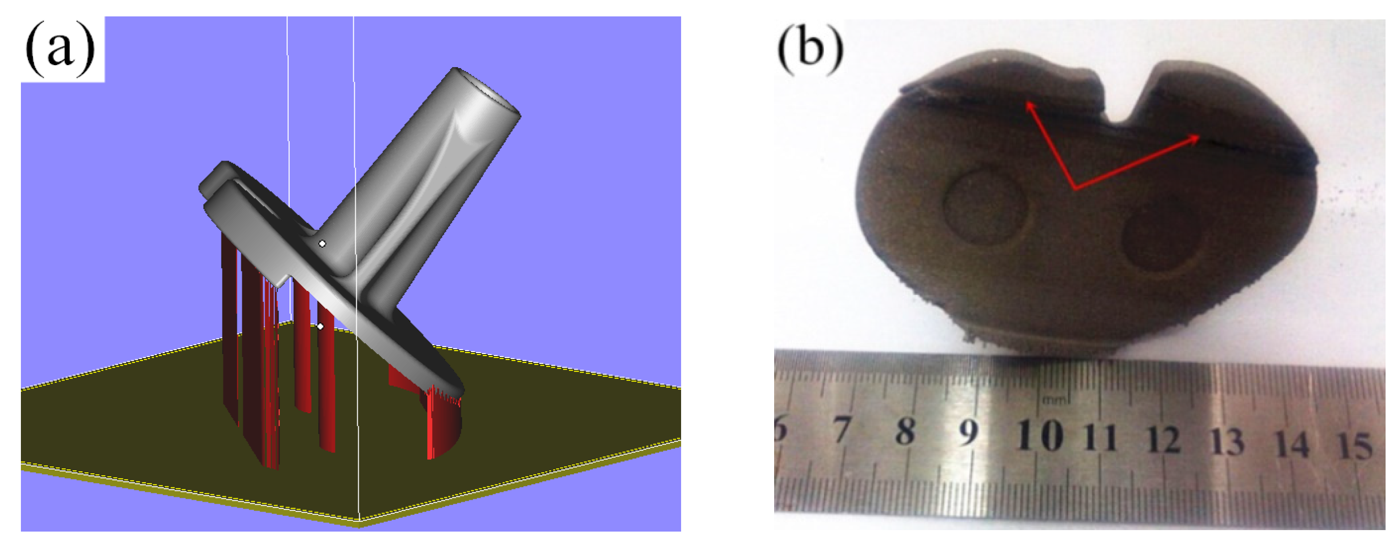
First, grid partition was carried out, then the constraint conditions of the model with the material of CoCrMo alloy after grid partition were set, the proximal tibia was fixed and 20 N loading was applied on the tibial articular surface. Finally, the time step and solution manner were set for solving. The finite element stress analysis results of the tibial implant were displayed in Figure 5. As can be observed in Figure 5, the tibial implant displacement mainly took place in the tibial articular surface border, while stress concentration mainly happened in the tibial tendon. Therefore, the tibial strength could be increased while stress concentration could be reduced through increasing the tendon thickness and distribution area.
The parameter control table in Autodesk Simulation Mechanical was opened to find the height and thickness parameters controlling the tibial tendon. The parameters were adjusted, the tendon thickness and distribution area were increased, and the updated model was confirmed.
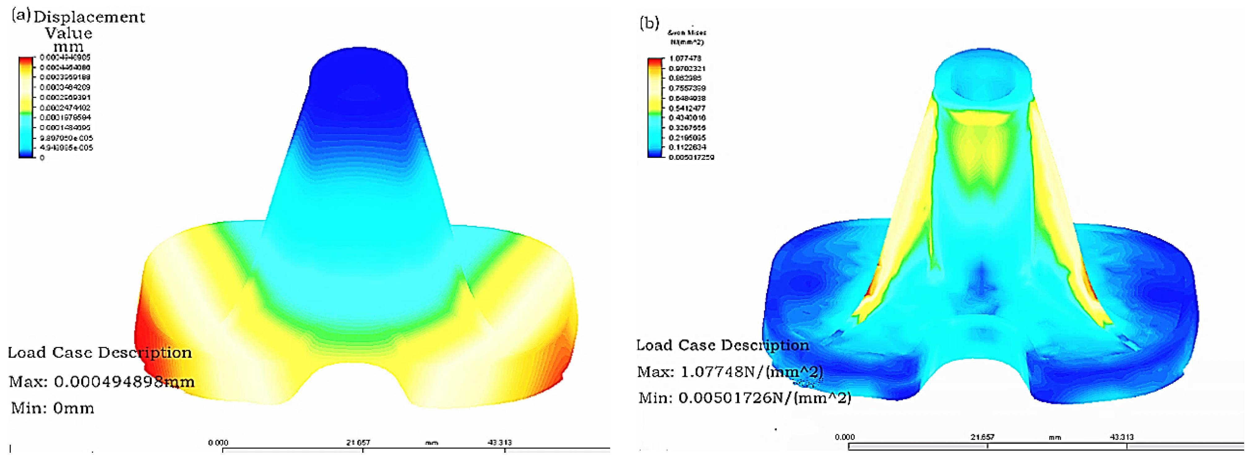
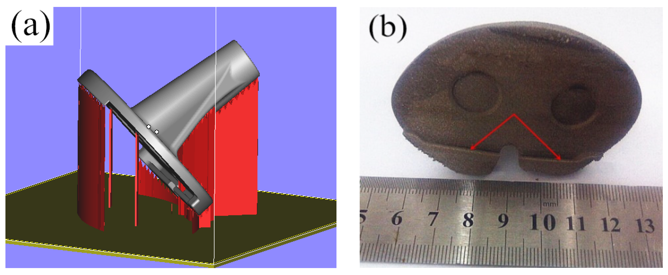
The updated tibial model was carried out with grid partition, and the constraint conditions, loading, time step and solution manner of the model with the material of CoCrMo alloy after grid partition were set before finding a solution. The finite element stress analysis results of the optimized tibial implant were displayed in Figure 6. As can be seen in the figure, the maximal displacement of the optimized tibial model was changed from 0.00322 mm in the original model to 0.00049 mm. In addition, the maximal stress of the optimized tibial model was changed from 8.198 N (mm2) in the original model to 1.077 (mm2). Clearly, the displacement strain of the optimized model was greatly reduced, and the stress distribution was more homogeneous and had achieved the goal of increasing tibial strength and reducing stress concentration.

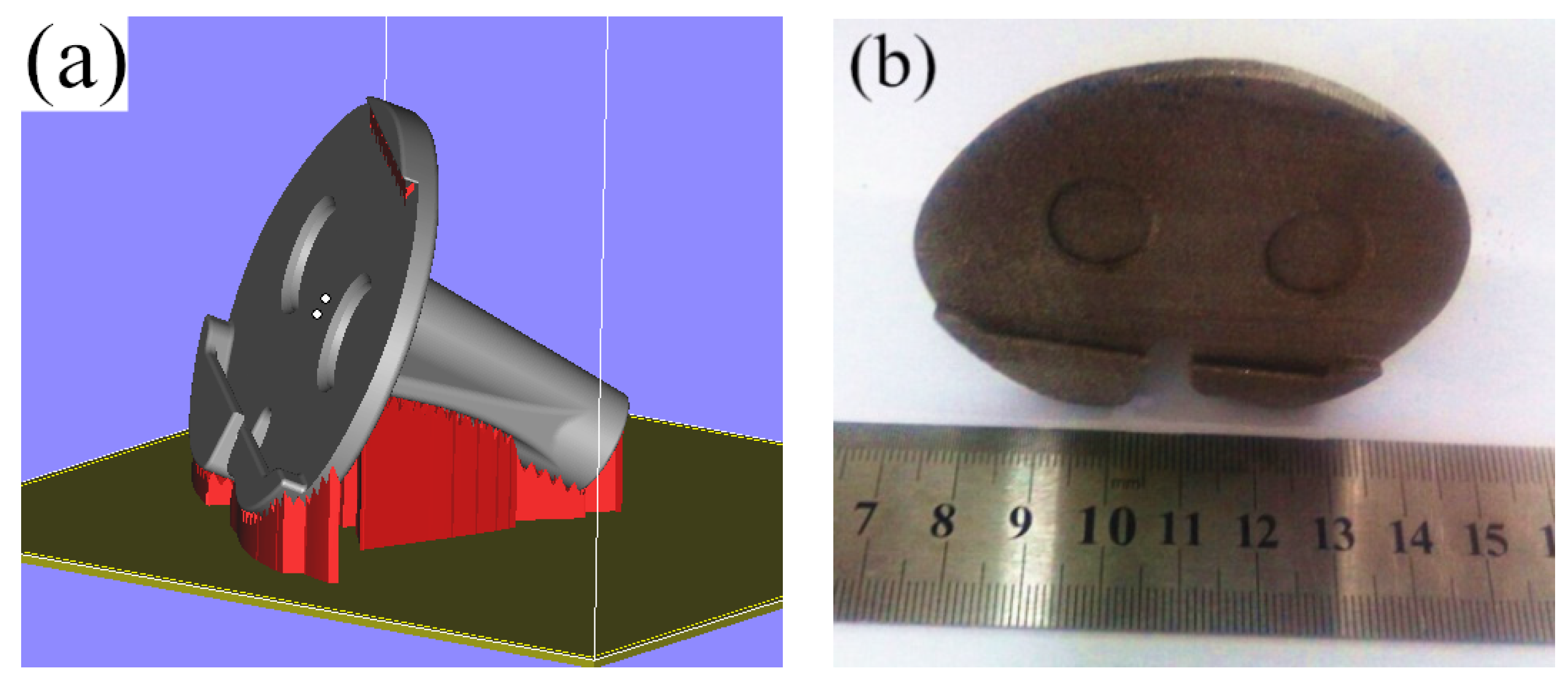
3.3. SLM Molding Tibial Implant Process Study

The molding quality and cost of the individualized implant parts are important influencing factors that determine whether the individualized implant can be successfully applied. The different placement manners at the time of SLM molding parts will lead to different structure additive amounts and molding layer thicknesses of the parts, which will directly affect the part molding quality and molding efficiency. Therefore, it is of great significance to investigate the molding effects of the SLM molding parts under different placement manners. In this section, the molding quality of the SLM molding tibial implant is optimized by changing the tibial implant placement manner.
The designed tibial implant was imported into Magics 15.01 in STL format for different placements of the part. First, the tibial implant placement position was adjusted to the conventional inclination of 45° for conventional placement. Subsequently, the structure was added, the part was sectioned at the layer thickness of 0.035 mm, the total layer of the part was 1532, and the molding time was 5.1 h, as shown in Figure 7a. In Figure 7a, the red part was the part structure, while the silver part was the tibial implant. It can be discovered through observing the surface quality of the SLM molding tibial implant in Figure 7b after removing the structure that the molding effect in the site contacting the structure was poor, and the surface quality of the tibial articular surface at the 45° suspending part was also poor. Moreover, there was an obvious adhering slag phenomenon, the fixation part of the tibial articular surface was partially deformed, and the additive structure in the recess site could hardly be removed, as denoted by the red notes in Figure 7b. The deformation in the fixation site of the tibial articular surface might be related to its contact with the structure during the molding process, while the poor surface quality on the tibial articular surface might be related to the excessive suspending. Consequently, further optimization of the tibial implant placement manner should be performed based on the above-mentioned problems.
On the account of the deformation of the fixation site of the tibial articular surface after SLM molding, the tibial fixation site could be overturned downward and could avoid the contact of recess in the fixation site of the tibial articular surface with the structure. Additionally, to improve the surface quality of the tibial articular surface, the inclination angle of the tibial articular surface could be reduced to avoid excessive suspending of the molding part. The part placement position was adjusted based on the above optimization principles after the addition of the structure, as shown in Figure 8a. Then, the part was sectioned at a layer thickness of 0.035 mm, a total of 1472 layers were obtained, and the molding time was 5.2 h. It could be discovered after observing the SLM molding part effect in Figure 8b that no obvious buckling deformation was observed in the fixation site of the tibial articular surface, and the tibial articular surface quality was also partially improved. However, optimizing the part placement manner could solve the above problems, but it would also lead to an increased additive amount of structure and molding time. Moreover, the tibial articular surface quality remains to be improved. Consequently, the placement manner of the tibial implant could be further optimized.
To improve the tibial articular surface molding quality, reduce the deformation in the fixation site of the tibial articular surface, and shorten the molding time, the tibial articular surface molding suspension could be further decreased, structure additive should be avoided in the fixation site of tibial articular surface, and the part molding height should also be reduced. The placement of the tibial implant was optimized based on the above considerations, and the optimized part placement manner is displayed in Figure 9a. After completing part position adjustment and structure addition, the part was sectioned at the layer thickness of 0.035 mm, a total of 1392 layers were obtained, and the molding time was 4.8 h. The SLM molding part effect is illustrated in Figure 9b. As can be observed, no buckling deformation was observed in the fixation site of the tibial articular surface, the tibial articular surface quality was improved, the part molding time was partially decreased, and the part satisfied the implantation requirements after post-processing.

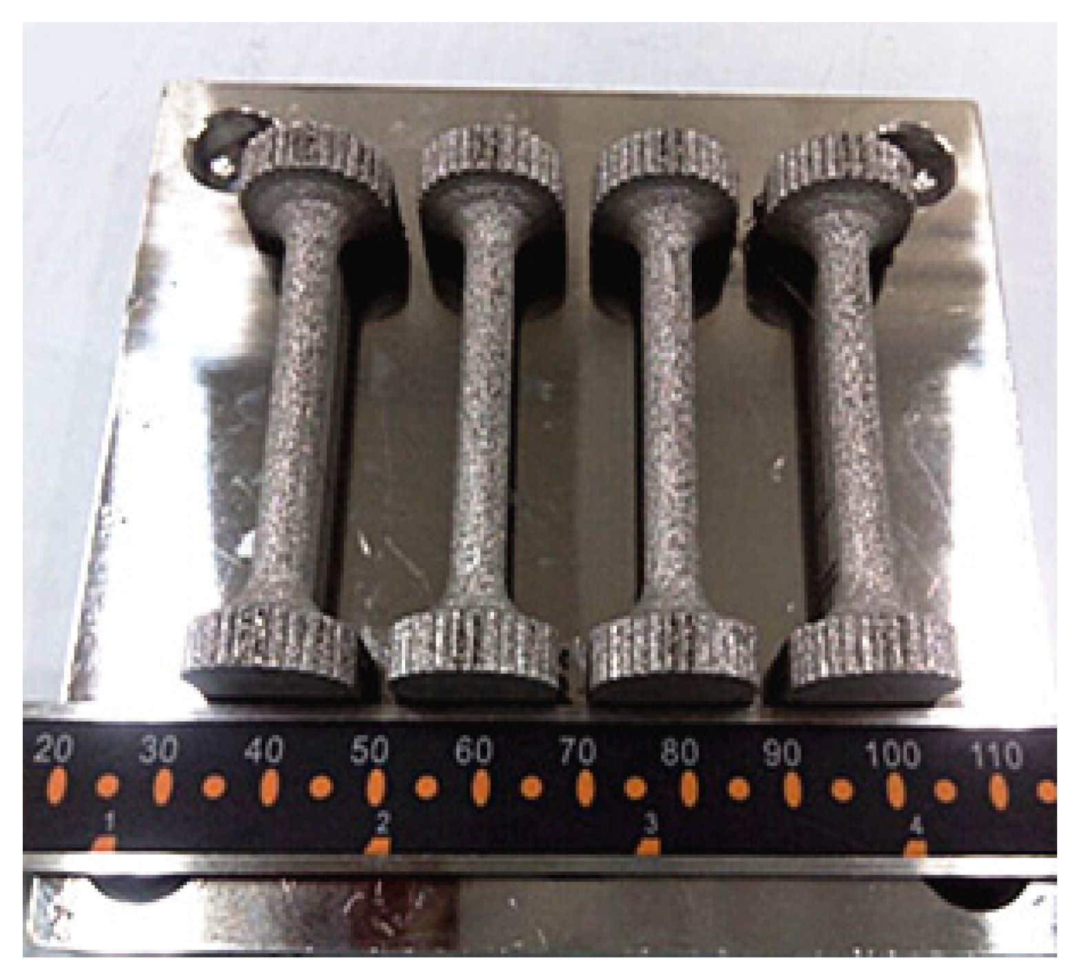
3.4. Tensile Property Study of the CoCrMo Alloy Part

The tensile pieces after SLM device molding were adopted, as shown in Figure 10. The test pieces were processed with simple polishing, and the surface roughness could reach 4.3 μm, which satisfied the requirements of the tensile test pieces.

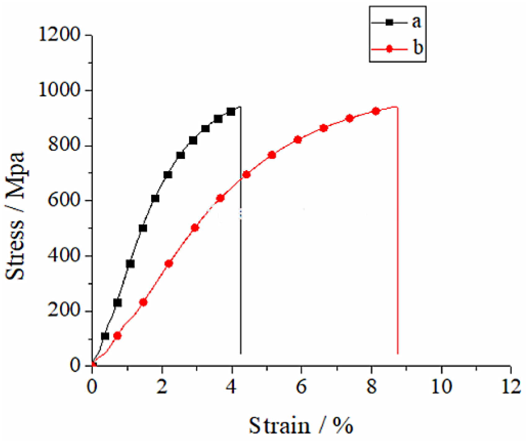
3.4.1. Stress–Strain Curve Analysis

The tensile test data of the CoCrMo alloy part under various manufacturing conditions were averaged, and the stress–strain curve was plotted, as displayed in Figure 11. It can be observed in Figure 11 that the stress–strain curve under various conditions suggests that the stress showed rapid linear growth with the increase in tensile strain capacity. When the strain capacity was increased to a certain degree, the stress growth trend became slow, and there was no linear relationship between the stress and strain. The stress–strain curve of the CoCrMo alloy part under various conditions displayed three stages, namely, the elastic deformation stage, yield stage and sharp drop stress stage. The stress was rapidly increased and decreased during the tensile process, which suggested that the fracture mechanism of the moulded CoCrMo alloy part was a brittle fracture. At the initial stage of the stress–strain curve, the variation rules of the SLM molding part and casting part of CoCrMo alloy part were basically similar. The strain capacity of the SLM molding part was short, and the variation trend was steep and high, indicating that it had high tensile intensity, with a fracture mechanism of brittle fracture. By contrast, the strain capacity of the casting part was long, the curve variation trend was gentle, and the height was slightly lower than that of the SLM molding part, revealing that its fracture mechanism was a ductile fracture.

3.4.2. Tensile Strength Analysis

Table 3 presents the mechanical property test results of the SLM molding part and casting part of the CoCrMo alloy. It can be seen by comparing the tensile strength test results in Table 3 with the human tibia in Table 1 that the tensile strength of the SLM molding part and casting part was far higher than that of the human tibia, demonstrating that the intensity of the SLM forming and casting parts of the CoCrMo alloy was satisfactory. Meanwhile, it can be seen by comparing the elasticity modulus test results in Table 3 with the human tibia in Table 1 that the elasticity modulus of the SLM molding part and casting part was far higher than that of the human tibia. Such findings revealed that the SLM molding and casting tibial implants would produce stress shielding after implantation into the human body, which was to the disadvantage of the growth of peripheral bone tissues. Moreover, it was found after comparing the SLM molding part and casting part that they had comparable tensile strength, while the SLM molding part had a higher elasticity modulus, which was not good for the growth of bone tissues, but the problem could be solved through the heat treatment method. The SLM molding tibial implant structure should be modified in the future, so as to reduce the stress shielding after implantation—for instance, partial porosity of the tibial implant.

4. Conclusions

(1)
Tibial implant is designed through the reversed combined with forward design methods, and the tibial implant model is optimized using the parametric FEM, which can minimize the stress concentration phenomenon of the implant part and realize the optimal distribution of force.
(2)
SLM molding tibial implant has a favorable molding effect after optimization of the molding techniques, with high tibial implant surface finish, but with no buckling deformation or obvious adhering slag.
(3)
The intensity of the SLM molding tibial implant can satisfy the implantation requirements, but it has a relatively high elasticity modulus, which should be solved with the heat treatment method in the future.
Certainly, subsequent studies are required to further understand the modeling and molding techniques of individualized knee implants, such as the parametric modeling of tibial implants, as well as the effects of the structural additive method and molding process parameters of SLM molding tibial implants on the molding quality, which can lay the foundation for directly manufacturing the individualized knee implant through SLM.

Author Contributions

G.Z. and J.L. completed the design of implants. X.Z. and Y.Z. completed the manufacturing. A.W. completed the analysis of implants. All authors have read and agreed to the published version of the manuscript.

Funding

The study was funded by the Henan Provincial Science and Technology Project (Grant No. 212102310859) and the Key Scientific Research Projects of Colleges and Universities in Henan Province (Grant No. 22A460006). Also, this work was supported by Analytical and Testing Center of ZKNUC for carrying out microscopic analysis.

Institutional Review Board Statement

Not applicable.

Informed Consent Statement

Not applicable.

Data Availability Statement

Data sharing is not applicable to this article.

Conflicts of Interest

The authors declare no conflict of interest.

References

  1. Knutson, K.; Lewold, S.; Robertsson, O.; Lidgren, L. The swedish knee arthroplasty register. a nation-wide study of 30,003 knees 1976-1992. Acta Orthop. Scand. 1994, 65, 375–386. [Google Scholar] [CrossRef] [PubMed] [Green Version]
  2. Blunn, G.W.; Joshi, A.B.; Minns, R.J.; Lidgren, L.; Lilley, P.; Ryd, L.; Engelbrecht, E.; Walker, P. Wear in retrieved condylar knee arthroplasties. a comparison of wear in different designs of 280 retrieved condylar knee prostheses. J. Arthroplast. 1997, 12, 281–290. [Google Scholar] [CrossRef]
  3. Bandyopadhyay, A.; Espana, F.; Balla, V.K.; Bose, S.; Ohgami, Y.; Davies, N.M. Influence of porosity on mechanical properties and in vivo response of ti6al4v implants. Acta Biomater. 2010, 6, 1640–1648. [Google Scholar] [CrossRef] [Green Version]
  4. Zhang, G.; Yang, Y.; Song, C.; Fu, F.; Zhang, Z. Study on biocompatibility of cocrmo alloy parts manufactured by selective laser melting. J. Med. Biol. Eng. 2018, 38, 76–86. [Google Scholar]
  5. Wei, L.; Liu, T.; Liao, W.; Jiang, L. Study on selective laser melting forming process of cobalt chromium alloy. Chin. J. Lasers 2015, 42, 63–70. [Google Scholar]
  6. Yang, Y.; Wang, D.; Wu, W. Research progress of direct manufacturing of metal parts by selective laser melting. Chin. J. Lasers 2011, 38, 0601007. [Google Scholar] [CrossRef]
  7. Song, C. Study on Digital Design and Direct Manufacturing of Customized Implant Based on Selective Laser Melting; South China University of Technology: Guangzhou, China, 2011. [Google Scholar]
  8. Chen, Z.; Zhang, Q.; Zhou, G.; Pang, Z.; Wei, Q. Three-dimensional parametric modeling during unicompartmental knee arthroplasty. Chin. J. Tissue Eng. Res. 2013, 4, 695. [Google Scholar]
  9. Wei, Z.; Li, H.; Xiong, X.; Zou, F.; Zou, Y. Treatment of severe tibial plateau fractures with 3D printed personalized plate internal fixation. Chin. J. Bone Jt. Inj. 2021, 36, 3. (In Chinese) [Google Scholar]
  10. Han, Y.; Kaken, H.; Zhao, W.; Wang, W.; Wang, L. Meta analysis of clinical efficacy of 3D printing assisted total knee arthroplasty. Biol. Orthop. Mater. Clin. Res. 2021, 18, 10. (In Chinese) [Google Scholar]
  11. Kumar, V.J.; Reddy, P.S.; Murthy, N.G. Modeling and biomechanical analysis of human knee joint. Int. J. Sci. Eng. Adv. Technol. 2014, 2, 246–252. [Google Scholar]
  12. Kumbhalkar, M.A.; Nawghare, U.; Ghode, R.; Deshmukh, Y.; Armarkar, B. Modeling and finite element analysis of knee prosthesis with and without implant. Univers. J. Comput. Math. 2013, 1, 56–66. [Google Scholar] [CrossRef]
  13. Abe, F.; Santos, E.C.; Kitamura, Y.; Osakada, K.; Shiomi, M. Influence of forming conditions on the titanium model in rapid prototyping with the selective laser melting process. Proc. Inst. Mech. Eng. Part C J. Mech. Eng. Sci. 2013, 217, 119–126. [Google Scholar] [CrossRef]
  14. Calignano, F. Design optimization of supports for overhanging structures in aluminum and titanium alloys by selective laser melting. Mater. Des. 2014, 64, 203–213. [Google Scholar] [CrossRef]
  15. Attarilar, S.; Ebrahimi, M.; Djavanroodi, F.; Fu, Y.; Wang, L.; Yang, J. 3D Printing technologies in metallic implants: A thematic review on the techniques and procedures. Int. J. Bioprint. 2021, 7, 306. [Google Scholar] [CrossRef] [PubMed]
Figure 1. Cylindrical tensile specimen.
Coatings 12 00561 g001
Figure 2. SLM manufacturing principle and apparatus: (a) The SLM manufacturing principle; (b) SLM equipment Dimetal-100.
Coatings 12 00561 g002
Figure 3. Reconstruction of reverse osteotomy of tibial implants: (a) CT image of knee joint; (b) Post reconstruction effect; (c) Bone cutting surface selection.
Coatings 12 00561 g003
Figure 4. Solid model of personalized tibial implant: (a) Stereogram of tibial prosthesis; (b) Overlook of tibial prosthesis.
Coatings 12 00561 g004
Figure 5. Results of finite element analysis of a tibial implant: (a) Displacement distribution; and (b) Stress distribution.
Coatings 12 00561 g005
Figure 6. Optimization results of tibial implant: (a) Displacement distribution; and (b) Stress distribution.
Coatings 12 00561 g006
Figure 7. The addition way of the tibial prosthesis support and the effect of SLM molding: (a) Conventional tilting 45-degree conventional placement; (b) Post forming effect of SLM.
Coatings 12 00561 g007
Figure 8. The addition way of the tibial prosthesis support and the effect of SLM molding: (a) Flipping of the fixed part of the tibial joint; (b) Post forming effect of SLM.
Coatings 12 00561 g008
Figure 9. The addition way of the tibial prosthesis support and the effect of SLM molding: (a) Flipping of tibial fixed column; (b) Post forming effect of SLM.
Coatings 12 00561 g009
Figure 10. Tensile test sample manufactured by SLM.
Coatings 12 00561 g010
Figure 11. Stress–strain curves of CoCrMo alloy: (a) SLM; (b) Cast.
Coatings 12 00561 g011
Table 1. Mechanical properties of bone.
MaterialExperimental DirectionModulus of Elasticity (Gpa)Compressive Strength (Mpa)
TibiaLongitudinal18.1159
Table 2. Comparison of powder materials used in SLM and ASTM F1377 standard.
ElementCoCrMo
Powder
ASTM F1377
Standard
ElementCoCrMo
Powder
ASTM F1377
Standard
Cr29.4%27–30%C0.15%<0.35%
Mo6%5–7%Ni0.09%<0.5%
Si0.8%<1%Al<0.010%<0.1%
Mn0.75%<1%Ti<0.010%<0.1%
Fe0.26%<0.75%W<0.010%<0.2%
N0.19%<0.25%CoBalanceBalance
Table 3. The mechanical properties of CoCrMo under different conditions.
SampleTensile Strength (Mpa)Modulus of Elasticity (Gpa)Extensibility A(%)
Cast985.92264.48.76
SLM978.96627.84.26
Publisher’s Note: MDPI stays neutral with regard to jurisdictional claims in published maps and institutional affiliations.

