Article

Study on AgCl/Al2O3 Catalyst Coating on Metal Workpiece Surface by Electrophoretic Deposition and Its Overall Catalytic Performance

1
Ningbo Haizhi Institute of Materials Industry Innovation, Ningbo 315000, China
2
School of Mechanical Engineering and Automation, University of Science and Technology Liaoning, Qianshan Mid-road, No.185, Anshan 114051, China
3
Department of Information System, Graduate School of Engineering, Saitama Institute of Technology, Fukaya 369-0293, Japan
4
Hainan Provincial Key Lab of Fine Chemistry, School of Chemical Engineering and Technology, Hainan University, Haikou 570228, China
5
Institute for Carbon-Neutral Technology, Shenzhen Polytechnic, Liuxian Street 7098, Nanshan District, Shenzhen 518055, China
*
Author to whom correspondence should be addressed.
Coatings 2022, 12(5), 553; https://doi.org/10.3390/coatings12050553
Submission received: 27 February 2022 / Revised: 6 April 2022 / Accepted: 7 April 2022 / Published: 20 April 2022
(This article belongs to the Special Issue Surface Modification and Functionalization for Advanced Materials)

Abstract

:
This paper is a study of the coating technique of AgCl/Al2O3 catalyst on metal-based surfaces. In order to remove nitrogen oxides from the exhaust of marine diesel engines, this paper proposes a method of electrophoretic deposition and designs an electrophoretic deposition apparatus according to the coating conditions. An in-house developed catalyst was coated on a specific stainless-steel workpiece by the electrophoretic deposition method under the conditions of appropriate voltage and catalyst solution concentration. The surface and cross section of AgCl/Al2O3 coating on stainless steel were observed by scanning electron microscope, and the thickness of catalyst coating after coating was determined. In this study, an exhaust gas evaluation system was built, and a removal test of nitrogen oxides from diesel exhaust gas was conducted under the environment of temperature cyclic change, and repeated experiments proved that the coated workpiece could still effectively remove harmful nitrogen oxides from the exhaust gas. Converting them to N2 provides a new idea for ship exhaust gas purification.

1. Introduction

With the accelerated development of the trend of economic globalization, trade between countries continues to strengthen, in which the shipping industry plays an important role. However, with the development of the economy and the shipping industry, the pollution of ships to the environment is becoming more and more serious, so it has gradually attracted people’s attention. Research on catalytic purification of diesel exhaust contaminants become one of the most difficult and hot topics in the field of environmental catalyst all over the world [1]. As the heart of the ship, diesel engine provides power for the navigation of the ship. Because it has the advantages of high thermal efficiency, wide power range, safety, and reliability, it has been widely used. At present, more than 98% of ships use diesel engines, diesel engines have complex chemical compositions, and with the change in engine working conditions, the composition of exhaust gas is also significantly different. The pollutants discharged by diesel engine include diesel shoot (PM), hydrocarbons (HC), CO, and NOx, etc.; among them, NOx causes great harm to the environment, which is considered to be the main reason for the formation of acid rain, In the developed shipping countries (such as Norway), 40% to 50% of the total NOx emissions comes from ships [2]. Therefore, how to effectively remove nitrogen oxides from diesel exhausts has become the focus of research.
In this study, we prepared a AgCl/Al2O3 catalyst, which can effectively convert NOx in tail gas into N2. This catalyst belongs to an HC-SCR catalyst, which uses HC as reducing agent to selectively reduce NOx in tail gas, so as to purify the environment. The chemical properties of this material are stable. After testing, the conversion efficiency of this catalyst for nitrogen oxides can reach more than 70%, and the repeated heating and cooling experiments show that this material has good stability [3,4,5,6].
In order to apply this material to the actual ship exhaust purification, it needs to be coated on the carrier. In the experiment, the catalyst material is coated on a specific stainless-steel workpiece by electrophoretic deposition method. This workpiece is designed into a honeycomb. The carrier with honeycomb structure can not only load more catalyst materials, but also make the gas fully contact and react with the catalyst. Electrophoretic deposition (EPD) is a method of using charge to produce coating or film on conductive objects. In the experiment, the stainless-steel workpiece is used as the negative electrode, the catalyst material has positive charge, moves directionally under the action of electric field, and forms a uniform catalyst coating on the surface of the workpiece. The operation of electrophoretic deposition method is simple, and the formed coating is uniform [7,8,9,10]. An exhaust gas simulation system is built to detect the catalytic performance of the whole workpiece after coating materials. The experiment simulates the environment of ship exhaust gas and tests its catalytic capacity for nitrogen oxides at different temperatures. After many experiments, it is proved that the whole workpiece can effectively convert nitrogen oxides into nitrogen, and the catalyst efficiency can reach more than 70%. This study provides a new idea for the research of ship exhaust purification materials.

2. Materials and Methods

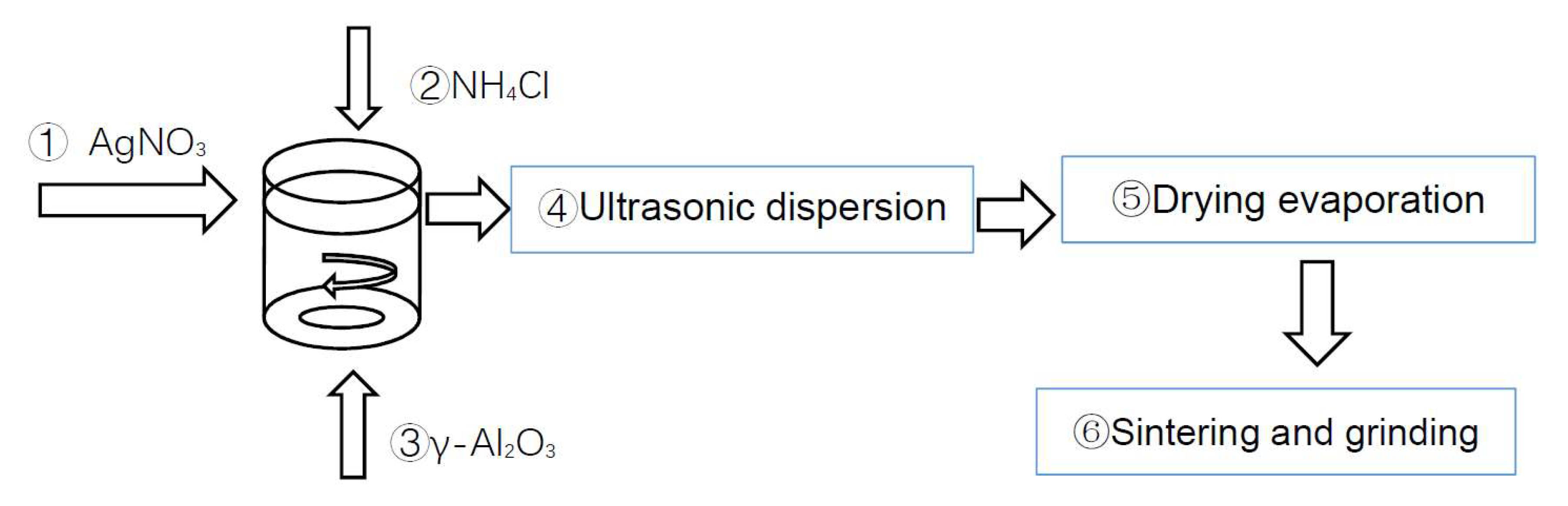
2.1. Preparation of Catalyst Materials

The experiment adopts the impregnation method, using AgNO3 and NH4Cl as raw materials. It generates AgCl as the active component of the catalyst through the reaction and was supported on γ-Al2O3. Additionally, γ-Al2O3 was used as catalyst carrier because of its large specific surface area. Figure 1 is the material preparation process.
Firstly, ammonium chloride (0.74 g) was added to the deionized water (100 mL); next, silver nitrate (2.38 g) was added to the solution and the obtained solution was uniformly stirred, and as a result, a large amount of white precipitate was produced in the solution. Then, γ-Al2O3 powder (46.89 g) was added to the mixture solution, and the obtained solution was uniformly stirred. The obtained solution was ultrasonically dispersed (40 KHz) for 30 min. The mixture solution was heated at 90 °C and stirred. The obtained mixture solutions were placed in the oven at 130 °C for 5 h, treated at 600 °C for 4 h. After cooling the obtained solids to the room temperature, the product was ground to 200 mesh to obtain catalyst material.
Figure 2 is the thermogravimetric analysis diagram of AgCl/Al2O3 catalyst. The heating rate was 5 °C/min, and the temperature rose from 23 to 700 °C. The relationship between the weight loss rate of AgCl/Al2O3 catalyst material and temperature could thus be obtained. After heating, the weight of the material decreased and a plateau appeared in the curve near 340 °C, which may be the loss of bound water of the catalyst material at high temperature. As the temperature continued to rise, the weight loss rate remained basically unchanged. The weight reduction rate of the catalyst was about 2.909%, indicating that the catalyst material had good thermal stability.

2.2. AgCl/Al2O3 Catalyst Material Performance Test

The chemical properties of this material are stable. After testing, the conversion efficiency of this catalyst for nitrogen oxides could reach more than 70%, and the stability of the chemical properties of the material was verified through repeated heating and cooling experiments. The experimental temperature rose from 200 to 500 °C, dropped to 200 °C, and then rose to 500 °C again. Observe its catalytic performance in the data chart given in Figure 3.
With the increase in temperature, the activity of the catalyst gradually increased, which could effectively convert NOx into N2. When the temperature reached 250 °C, the conversion rate exceeded 90%, and with the increase in temperature, the conversion rate of NOx by the catalyst was close to 100% at 300–450 °C. However, when the temperature continued to rise, the NOx conversion rate gradually decreased, because the excessive temperature inhibited the activity of the catalyst. When the temperature began to decrease, the NOx conversion rate gradually increased, and the NOx conversion rate of the catalyst was close to 100% at 250–400 °C. When the temperature continued to decrease, the NOx conversion rate gradually decreased, which indicates that too low temperature is also not conducive to the work of the catalyst. When the temperature was raised again, the conversion curve of the catalyst is similar to that at the first temperature rise, indicating that the catalyst material had good stability.

3. Electrophoretic Deposition Coating Experiment

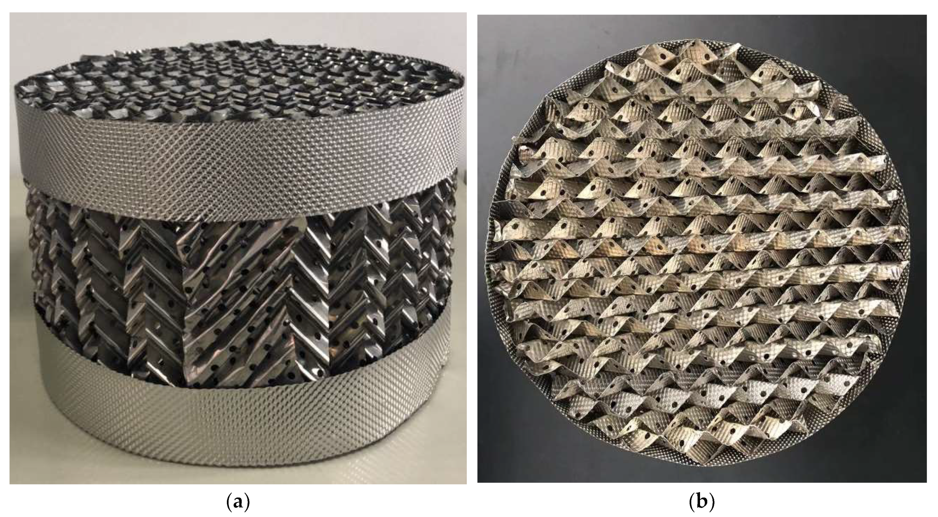
3.1. Design of Carrier Workpiece

The metal stainless-steel carrier was designed to meet the requirement that the catalyst material can be coated on its surface. As an integrated post-processing device, it can be used for ship tail gas purification. This metal carrier was made of SUS304 stainless steel. As shown in Figure 4, the carrier workpiece was a cylinder, and the bottom surface was a circle with a diameter of 300 mm and a height of 200 mm. Its interior was composed of baffles with honeycomb structure. Small holes were distributed on the baffles to facilitate the passage of intermediate gas. This design could effectively carry more catalyst materials on the surface. At the same time, when the gas passed through the workpiece, the structure of the baffles could make the gas stay in the workpiece for a longer time. Thus, the catalyst could participate in the reaction more fully. At the same time, in the subsequent electrophoretic deposition experiment, the carrier workpiece was used as a negative electrode, and its good conductivity was conducive to the electrophoretic deposition experiment.

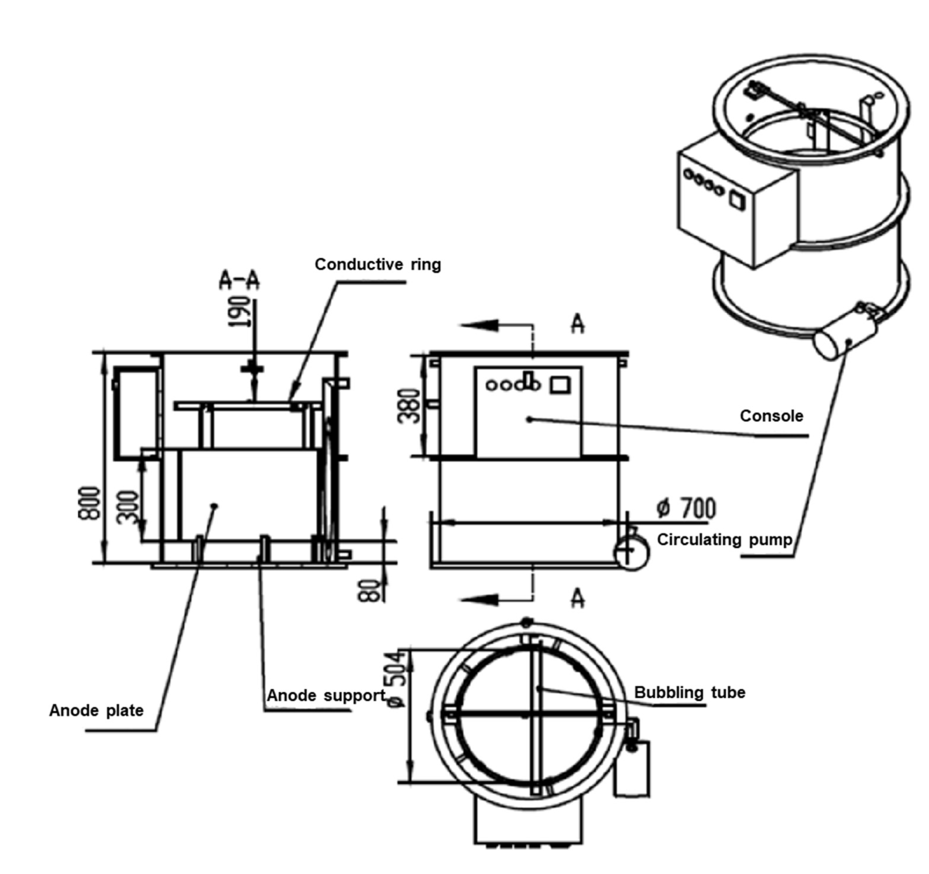
3.2. Design of Electrophoretic Deposition Device

Because of the size of the carrier metal workpiece, it was necessary to design a specific electrophoretic deposition device to perform the coating experiment. The electrophoretic deposition device was composed of a rectifier and an electrophoretic deposition tank, as shown in Figure 5. The rectifier was used as a power supply to provide energy for the electrophoresis of catalyst materials. The material of the electrophoretic deposition tank was polypropylene, and the interior of the tank was cylindrical. This design was used to make the catalyst materials more evenly distributed in the liquid. The electrophoretic deposition tank was equipped with a circulating device. The liquid in the tank was pumped to the top notch through the magnetic pump and flowed into the deposition tank, which could effectively disperse the material evenly in the liquid and avoid the bottom sinking of the catalyst material. In order to disperse materials, a stirring device was also installed in the electrophoretic deposition tank to achieve the purpose of stirring through the bubbles at the bottom of the tank. At the same time, compared with mechanical stirring, bubble stirring could avoid too violent stirring, which would affect the flatness of the coating surface.
The stainless-steel carrier workpiece was connected to the negative pole of the rectifier as the cathode, and the positive pole of the rectifier was connected to the anode plate. The anode plate was made of aluminum, with a ring shape, an inner diameter of 492 mm, an outer diameter of 500 mm, a wall thickness of 4 mm, and a height of 300 mm. The anode aluminum tube was fixed in the deposition tank through the bottom tray and connected with the rectifier through the top copper sheet. The bottom end of the anode was about 250 mm away from the bottom of the tank. The catalyst material was dispersed in the deposition liquid, and the catalyst particles were positively charged. Under the action of an external electric field, the material particles moved to the cathode by controlling voltage, temperature, time, and other conditions, so that the catalyst material was coated on the workpiece.

3.3. Coating Experiment

The steps of coating experiment are shown in Figure 6. The electrophoretic deposition experiment was completed through water washing, acid pickling, further water washing, electrophoretic deposition, workpiece drying, and workpiece sintering.
The first water washing was conducted to remove the impurities on the workpiece, initially clean the workpiece, and then put the washed metal carrier workpiece into the pickling tank for pickling. The purpose of pickling was to remove the oxide skin on the surface of the stainless-steel workpiece and improve the bonding ability between coating and workpiece. After the second water washing, the purpose was to remove the residual organic acid on the surface after pickling. After washing, the workpiece was connected to the hanger, hung in the center of the deposition tank as a whole, the cathode was connected at the other end of the hanger, the positive and negative poles of the rectifier were connected to the anode and cathode of the deposition tank, respectively, the deposition solution was prepared and poured into the tank, the catalyst powder material was added to be deposited, the circulation system and bubble stirring device were opened for electrophoretic deposition, and the voltage was adjusted during the deposition process. We observed the coating of the material under different currents and voltages. After the deposition experiment, we turned off the power supply, put the deposited workpiece into the drying oven for drying, put the workpiece into the muffle furnace for sintering after the surface was completely dry, and changed the sintering temperature according to the material thermogravimetric analysis diagram for the experiment to obtain the appropriate sintering temperature so as to make the powder catalyst material more dense and improve the bonding ability between the coating and the workpiece. The detailed experimental steps are as follows:
  • Water washing: place the workpiece to be deposited in the water washing bucket, wash it continuously with deionized water, and take it out after placing it in the water washing bucket for 30 min.
  • Pickling: immerse the stainless-steel workpiece in the pickling solution. Set the temperature of the pickling solution at 20–30 °C, and use an immersion time of 50 min to 60 min.
  • Water washing: take out the pickled workpiece, put it into the water washing bucket again for washing, wash off the residual acid washing solution on the surface, and take it out after putting it in the water washing bucket for 30 min.
  • Use Al (NO3) 3 · 9H2O as binder to heat treat Al (NO3) 3 · 9H2O. After heating at 135 °C for 1 h, obtain 60 wt.% aluminum salt. Dissolve the aluminum salt after heat treatment in the mixed solution of deionized water and absolute ethanol (deionized water: ethanol = 1:1) and conduct ultrasonic dispersion at room temperature for 30 min until the material is completely dissolved.
  • Preparation of deposition solution: mix ethanol and deionized water 1:1 into the deposition tank, and mix the deposition solution evenly using a gas stirring device and circulating device.
  • Add the catalyst material into the deposition liquid, and evenly mix the deposition liquid using the gas stirring device and the circulating device.
  • Connect the pretreated workpiece using a hanger and put into the deposition tank. Connect the cathode of the rectifier to the plating racks, and connect the anode of the rectifier to the anode plate. Open the bubbling device and circulating water device, measure the temperature and pH of the deposition solution before deposition, adjust the voltage to 120 V, perform electrophoretic deposition for a certain time, and end the experiment. Disconnect the power supply, and take the workpiece out of the electrophoretic deposition tank.
  • Put the deposited workpiece into the drying oven, and take it out after drying at 130 °C for 1 h.
  • Sintering: set the sintering temperature at 600 °C in the experiment, put the workpiece in the muffle furnace, set the program, raise the temperature to 600 °C, and set the heating time as 1 h. After sintering at 600 °C for 4 h, stop the system and take out the workpiece after the temperature drops to room temperature. This coating process is based on the specific conditions of this study [11,12].

3.4. Exhaust Purification Test Experiment

3.4.1. Design of Exhaust Purification Test System

In order to test the catalytic effect of the catalyst coating on the coated workpiece surface on NOx, a catalytic performance evaluation system was built. By simulating the exhaust gas intake, the mixed gas containing a certain proportion of NOx passed through the integrated post-treatment device under high-temperature conditions. The NOx content after reaction was detected by flue gas detector so as to obtain the catalytic performance of the integrated post-treatment device coated with catalyst coating. The exhaust purification test system consisted of an intake system, reaction system, and analysis system, as shown in Figure 7.
The intake system is composed of component gas, gas phase generator, and gas distributor. The component gas was mainly NO, O2, and N2. C2H5OH was mixed with H2O as reducing gas and heated by gas-phase generator to enter the heating furnace in the form of steam. The three gases were connected to the tubular furnace through the gas distributor. The flow of component gases could be input into the gas distributor to accurately control the distribution ratio of the gas components entering the tubular furnace.
The reaction system was mainly tubular furnace. The overall size was 64 cm long × 76 cm wide × 115 cm high. The central quartz tube was 85 cm and 35 cm in diameter. Both ends were fixed and sealed by flanges. The analysis system was composed of a flue gas analyzer and a connected computer. The flue gas analyzer was equipped with German advanced NO and NO2 detection optical sensors. After the reaction in the heating tubular furnace, part of the gas entered the flue gas analyzer through the pipeline to detect the content of residual NOx, and the data were collected through the connected computer.
Test conditions: C2H5OH was used as reducing agent, and the total gas flow rate was about 10 L/min. There were four kinds of gas distribution used in this test: NO (20,000 ppm), O2, N2, C2H5OH/H2O = 2:3. NOx: 2000 ppm (1 L/min), O2: 2 L/min, and N2 as equilibrium gas (7 L/min).
After being mixed with the deoxidizing agent C2H5OH through the main inlet pipe of the steam generator, the deoxidizing agent entered the main inlet pipe and was controlled by the steam flow meter. The workpiece was placed in the quartz tube of the heating tubular furnace. Both ends of the quartz tube were fixed with flanges to play the role of sealing. At the same time, the inlet pipe and outlet pipe were connected at both ends of the flange, respectively. The reaction temperature range during the experiment was 250–400 °C. The content of residual NOx was detected by the flue gas analyzer after the reaction. The computer was connected to the flue gas analysis to record the content of NOx after the reaction in real time, and data were collected every 30 s. The collected data were collected, and the conversion rate of NOx was calculated. The calculation formula is as follows:
NO x   conversion = ( 1 NO x out NO x in ) × 100 %

3.4.2. Experimental Process

The metal workpiece was put into the quartz tube, and the furnace temperature was set. This experiment tested the conversion rate of NOx at four temperature points of 250, 300, 350, and 400 °C in the temperature range of 250 to 400 °C. The heating furnace rose from room temperature to 250 °C, the heating time was 30 min, the heating time at 250 °C was 20 min, the heating time at 250–300 °C was 10 min, the heating time at 300 °C was 20 min, and the heating time at 300–350 °C was 10 min. Heat was preserved at 350 °C for 30 min, then raise the temperature from 350 to 400 °C for 10 min, and heat was preserved at 400 °C for 40 min. The heating device of the heating furnace was turned off, and we continued to inject mixed gas for cooling until the temperature dropped to 250 °C. The data of NOx conversion rate during heating and cooling were recorded by a computer.
The gas composition was N2: 7 L/min, O2: 2 L/min, NOx: 1 L/min, and C2H5OH/H2O (volume ratio 2:3). In order to verify the service life of catalyst coating, three repeated experiments were carried out under the same conditions. The data were collected and processed by a computer.

4. Results and Discussion

4.1. Electrophoretic Deposition Experiment

After the electrophoretic deposition experiment, a catalyst coating was formed on the surface of the metal carrier. The catalyst coating and cross section on the surface of the metal carrier were observed by SEM. Figure 8 shows the apparent morphology of the catalyst coating magnified by 2000 times, respectively. It can be seen from the SEM that the surface of the catalyst coating obtained by electrophoretic deposition method was dense and uniform.
Figure 9 shows the SEM images and EDS linescan spectra of the cross section; (a) is the SEM image of the section of the substrate and coating. From the figure, it can be seen that the cross section of the material was flat and uniform, and the thickness of the catalyst coating was about 30 μm. (c) is the EDS spectra of the section. It can be seen from the figure that the catalyst layer contained Ag, Cl, Al, and O. It is verified that the coating was AgCl/Al2O3 catalyst.

4.2. Analysis of Test Results of Exhaust Purification

In the experiment, the exhaust purification test system was used to test the catalytic performance of the integrated post-treatment device for NOx in the exhaust gas. In order to verify the catalytic activity and service life of the catalyst material, the same catalyst was tested three times under the same test conditions; the process diagram is shown in Figure 10. The content of NOx in the exhaust gas was recorded by the flue gas analyzer, and then the processed data were obtained, as in Figure 11.
Experiments b and c are repeated experiments carried out under the same test conditions as a in order to verify that this material can still maintain high activity after repeated heating and cooling.
According to the analysis of the change diagram of NOx conversion rate with temperature obtained in experiment a, after the catalyst was heated and activated, when the temperature reached 400 °C, the NOx conversion rate reached 76%, indicating that NOx in the tail gas could be effectively converted into N2 under the action of the catalyst. When the temperature was maintained at 400 °C, the conversion of the catalyst was maintained at 75–78%.
With the decrease in temperature, the NOx conversion rate increased gradually, indicating that the activity of the catalyst was enhanced, thus more fully converting NOx in the exhaust gas. In the range of 270–290 °C, the conversion rate of catalyst to NOx could reach 85%, whereas the diesel engine produced more NOx due to insufficient combustion in this temperature range. Therefore, the research and development of the catalyst is conducive to the purification of ship exhaust. In order to study the stability of the catalyst, repeated experiments were carried out to study its reproducibility. After several temperature rises and falls, although the NOx conversion rate decreased slightly, the data curves obtained from the two experiments were basically consistent with the first one, indicating that the catalyst still maintained good activity and had good stability. In Figure 1 of reference [13], the conversion of NOx over 2% AgCl/Al2O3 catalyst exceeded 80% in the range of 350–550 °C. In this study, although the catalytic performance of the coated catalyst coating was lower than that of the catalyst powder before coating, the conversion of NOx could still exceed 80%, which indicates that the electrophoretic deposition coating method did not have a great impact on the performance of the catalyst [13].

5. Conclusions

According to the experimental conditions, the electrophoretic deposition device was designed to carry out the electrophoretic deposition coating experiment on the surface of specific stainless-steel workpiece, and the tail gas purification test system was designed to simulate the NOx component in diesel tail gas and test the ability of the device to convert NOx into N2 in integrated post-treatment.
Based on the analysis of the achieved test results, the following conclusions have been reached:
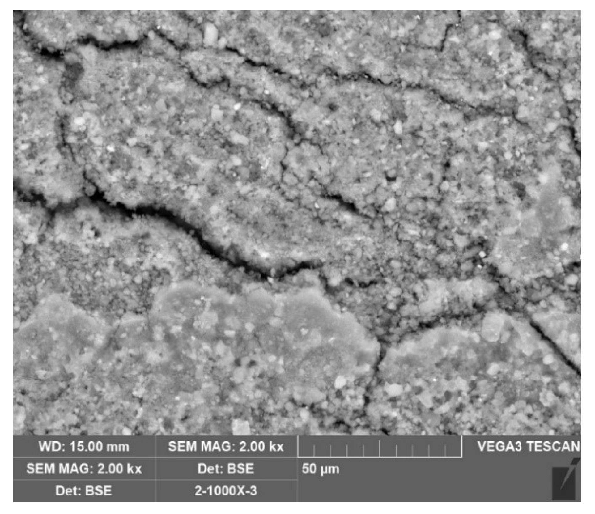
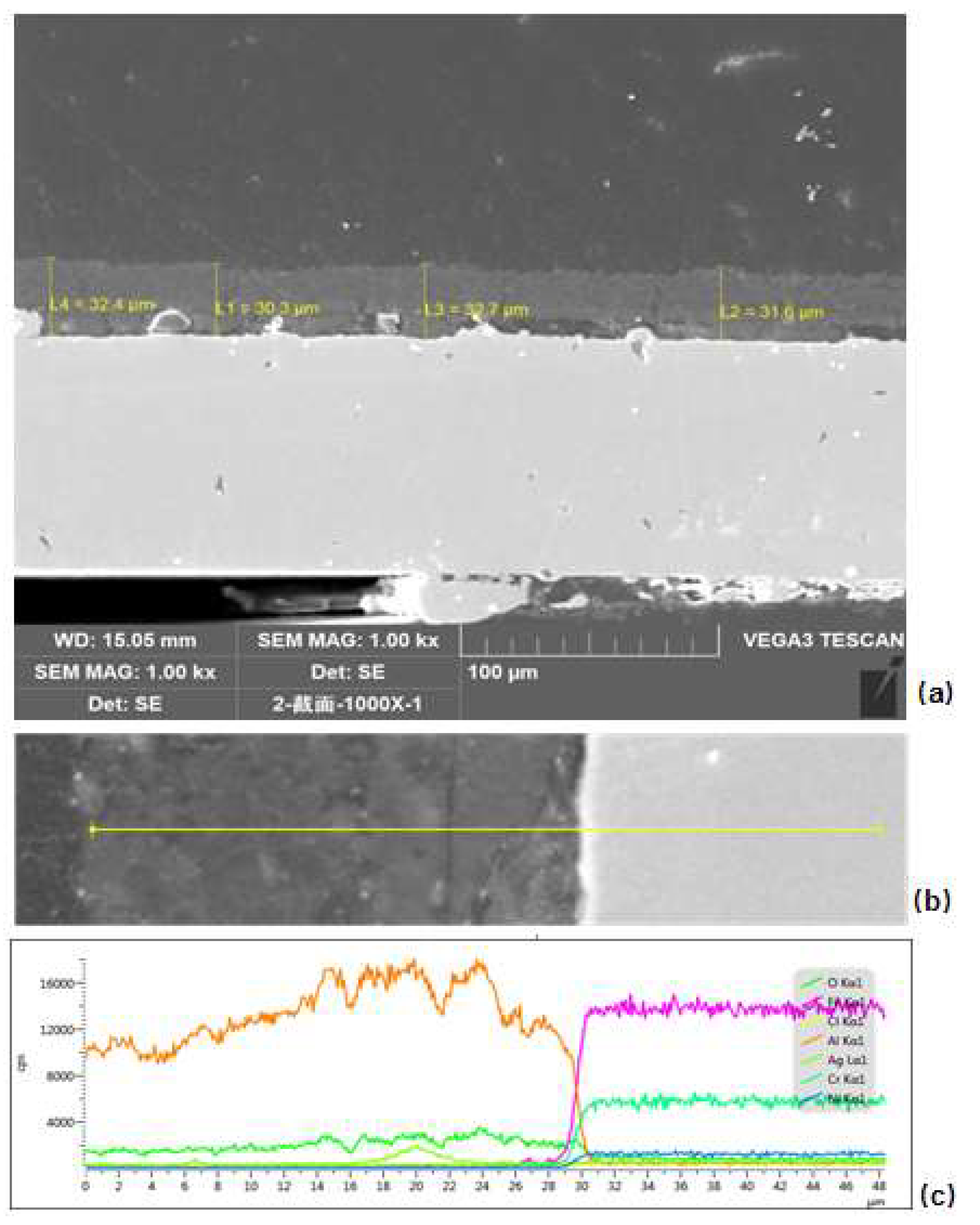
  • After electrophoretic deposition, a AgCl/Al2O3 catalyst was successfully coated on a stainless-steel workpiece to make an integrated post-treatment device. After SEM observation, a uniform and dense catalyst coating was formed on the surface of the workpiece. By observing the cross section, the thickness of the catalyst coating was about 30 μm.
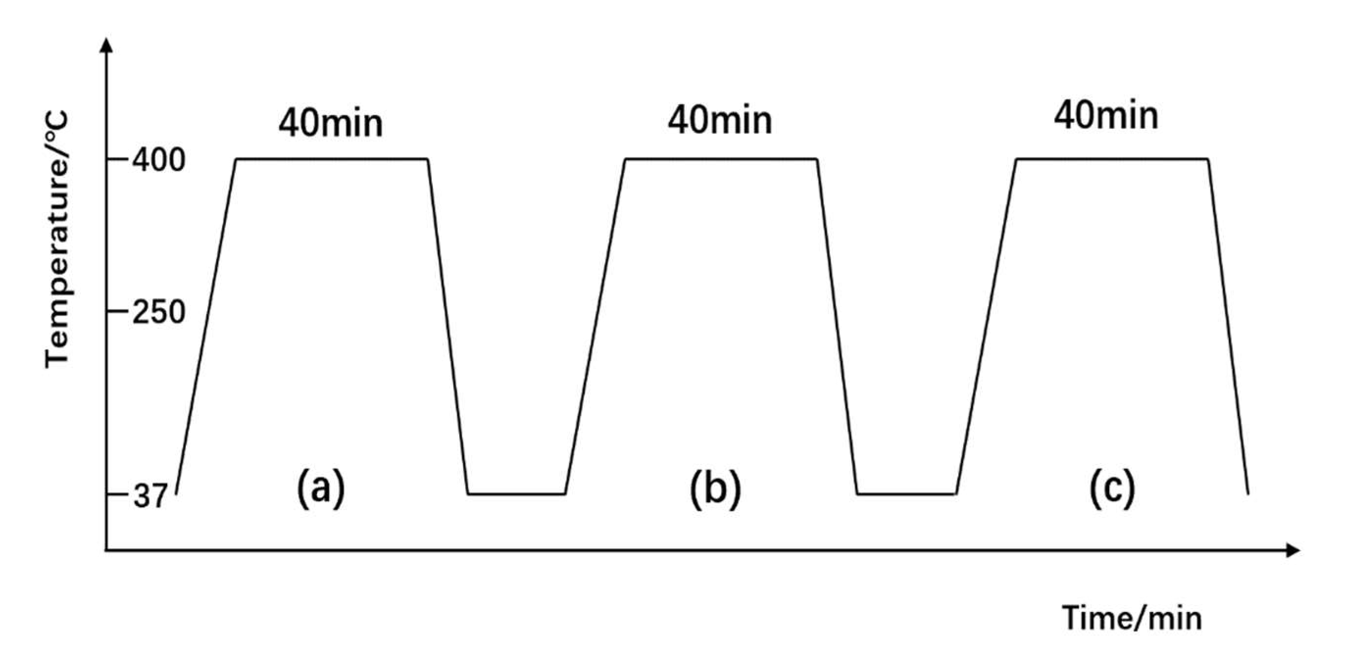
  • Through the repeatability experiment of the integrated post-treatment workpiece, it is proved that the catalyst coating coated on the workpiece surface had good stability, the catalyst maintained high catalytic activity after multiple reactions, and the conversion efficiency could reach more than 70%, thus effectively converting NOx in the tail gas into nitrogen. This study provides a new idea for the development of a marine exhaust purification catalyst.

Author Contributions

Conceptualization, Y.Y. and D.J.; methodology, Y.Y. and D.J.; formal analysis, Y.Y. and D.J.; investigation, Y.Y., D.J. and Y.D.; data curation, Y.Y. and D.J.; writing—original draft preparation, Y.Y.; writing—review and editing, Y.Y. and D.J. All authors have read and agreed to the published version of the manuscript.

Funding

Shanghai Marine Diesel Engine Research Institute (SMDERI) and National Key R&D Program of China (2017YFE0116200).

Institutional Review Board Statement

Not applicable.

Informed Consent Statement

Not applicable.

Data Availability Statement

The data presented in this study are available on request from the corresponding author.

Acknowledgments

This research was supported and funded by Shanghai Marine Diesel Engine Research Institute (SMDERI) and National Key R & D Program of China (2017YFE0116200), for which we would like to express our sincere gratitude.

Conflicts of Interest

The authors declare no conflict of interest.

References

  1. Srivastava, N.K.; Majumder, C.B. Novel biofiltration methods for the treatment of heavy metals from industrial waste water. J. Hazard Mater. 2008, 1, 1–8. [Google Scholar] [CrossRef] [PubMed]
  2. Zhang, X.-L.; He, H.; Ma, Z.-C. Hydrogen promotes the selective catalytic reduction of NOx by ethanol over Ag/Al2O3. Catal. Commun. 2007, 2, 187–192. [Google Scholar] [CrossRef]
  3. He, H.; Yu, Y.-B. Selective catalytic reduction of NOx over Ag/Al2O3 catalyst: From reaction mechanism to diesel engine test. Catal. Today 2005, 100, 37–47. [Google Scholar] [CrossRef]
  4. Yu, Y.-B.; He, H.; Feng, Q. Novel enolic surface species formed during partial oxidation of CH3CHO, C2H5OH, and C3H6 on Ag/Al2O3: An in situ DRIFTS study. J. Phys. Chem. B. 2003, 47, 13090–13092. [Google Scholar] [CrossRef]
  5. Yoshida, Q.K. Characterization of an AgCl/Al2O3 catalyst for lean NO conversion. Phys. Chem. Chem. Phys. 1999, 14, 3365–3367. [Google Scholar]
  6. Yu, Y.-M.; Sato, S.; Zhou, W.-M.; Tian, H.; Ju, D.-Y. Study on the Effect of Different Preparation Methods on the Performance of AgCl/Al2O3 Catalyst Used for Diesel Exhaust Treatment. J. Thermodyn. Catal. 2020, 11, 208. [Google Scholar]
  7. Rehman, M.A.U.; Bastan, F.E.; Haider, B.; Boccaccini, A.R. Electrophoretic deposition of PEEK/bioactive glass composite coatings for orthopedicimplants: A design of experiments (DOE) study. J. Mater. Des. 2017, 130, 223–230. [Google Scholar] [CrossRef]
  8. Kahradeh, K.H.; Saievar-Iranizad, E.; Bayat, A. Electrophoretically deposited carbon micro and nanospheres thin films as superhydrophobic coatings. J. Surf. Coat. Technol. 2017, 319, 318–325. [Google Scholar] [CrossRef]
  9. Hafedh, D.; Nader, B.-J.; Florica, S.-L.; Joel, F.; Larbi, A.B.C.; Hicham, B. Effect of annealing temperature on the structural and mechanical properties of coatings prepared by electrophoretic deposition of TiO2 nano particles. J. Thin Solid Film. 2017, 638, 201–212. [Google Scholar]
  10. Zhao, W.-T.; Shi, J.-L.; Guo, Q.-G.; Song, J.-R.; Liu, L. SiC coating by electrophoretic deposition on graphite substrate. J. Space Mater. Technol. 2008, 4, 51–54. [Google Scholar]
  11. Sun, H.; Quan, X.; Chen, S.; Zhao, H.; Zhao, Y. Preparation of well-adhered γ-Al2O3 washcoat on metallic wire mesh monoliths by electrophoretic deposition. Appl. Surf. Sci. 2007, 253, 3303–3310. [Google Scholar] [CrossRef]
  12. Fan, X.-D.; Liang, H.; Xu, M.-X.; Xu, T.-X. Study on electrophoretic deposition processing of Al2O3 microporous membranes. J. Tianjin Univ. 2000, 33, 663–664. [Google Scholar]
  13. Wang, Z.-J.; Xu, G.-Y.; Liu, X.; Yu, Y.-B.; He, H. Investigation of Water and Sulfur Tolerance of Precipitable Silver Compound Ag/Al2O3 Catalysts in H2 -Assisted C3H6-SCR of NOx. J. ACS Omega 2020, 5, 29593–29600. [Google Scholar] [CrossRef] [PubMed]
Figure 1. Material preparation process.
Coatings 12 00553 g001
Figure 2. Thermogravimetric analysis of catalyst materials.
Coatings 12 00553 g002
Figure 3. The catalytic activity of AgCl/Al2O3.
Coatings 12 00553 g003
Figure 4. Carrier workpiece. (a) Carrier front view; (b) Carrier vertical view.
Coatings 12 00553 g004
Figure 5. Structural diagram of electrophoretic deposition device.
Coatings 12 00553 g005
Figure 6. Coating experiment process.
Coatings 12 00553 g006
Figure 7. Exhaust purification test system concept map.
Coatings 12 00553 g007
Figure 8. SEM image of coating surface (2.00 kx).
Coatings 12 00553 g008
Figure 9. SEM images and EDS linescan spectra of section. (a) SEM image of the section of the substrate and coating; (b) EDS line scan position; (c) EDS spectra of the section.
Coatings 12 00553 g009
Figure 10. Schematic diagram of test process. (a) The first experiment; (b) The second experiment; (c) The third experiment.
Coatings 12 00553 g010
Figure 11. Curve of NOx conversion with temperature. (a) The first experiment; (b) The second experiment; (c) The third experiment.
Coatings 12 00553 g011
Publisher’s Note: MDPI stays neutral with regard to jurisdictional claims in published maps and institutional affiliations.

