Article

Microstructure and Properties of Hydroxyapatite Coatings Made by Aerosol Cold Spraying–Sintering Technology

by
Grzegorz Kubicki
1,2,*,
Volf Leshchynsky
1,3,*,
Ahmed Elseddawy
3,
Maria Wiśniewska
1,
Roman G. Maev
3,
Jarosław Jakubowicz
4 and
Joanna Sulej-Chojnacka
1
1
Łukasiewicz Research Network—Poznań Institute of Technology, 6 Ewarysta Estkowskiego St., 61-755 Poznan, Poland
2
Faculty of Materials Engineering and Technical Physics, Poznan University of Technology, 24 Jana Pawla II St., 61-138 Poznan, Poland
3
Institute for Diagnostic Imaging Research, 688 University Avenue West, Windsor, ON N9A 5R5, Canada
4
Institute of Materials Science and Engineering, Poznan University of Technology, 24 Jana Pawla II St., 61-138 Poznan, Poland
*
Authors to whom correspondence should be addressed.
Coatings 2022, 12(4), 535; https://doi.org/10.3390/coatings12040535
Submission received: 29 March 2022 / Revised: 10 April 2022 / Accepted: 13 April 2022 / Published: 15 April 2022
(This article belongs to the Special Issue Advances in Cold Spraying for Thin Film Preparation)

Abstract

:
Hydroxyapatite is a widely used material used for the bioactivation of an implant’s surface. A promising hydroxyapatite coating approach is the kinetic deposition of powder particles. The possibility of solid-state deposition improvement through the merging of Aerosol Deposition and Low Pressure Cold Spraying techniques is a promising prospect for improving the deposition efficiency and the quality of coatings. The objective of the paper is to study the possibilities of hydroxyapatite coating structure modification through changes in the coating process and post-heat treatment. The novel Aerosol Cold Spraying system joining Low Pressure Cold Spraying and Aerosol Deposition was used for the deposition of coatings. The coating’s post-processing was conducted using two techniques: Spark Plasma Sintering and Pressureless Sintering. The coating’s structure was examined using scanning, transmission, and light microscopy, and X-ray diffraction. Substrate–coating bond strength was assessed using a tensile test. Homogenous buildup using Aerosol Cold Spraying of hydroxyapatite was achieved. Various pores and microcracks were visible in the sprayed coatings. The deposition process and the thermal post-processing did not lead to significant degradation of the hydroxyapatite phase. As a result of the Spark Plasma Sintering and Pressureless Sintering at 800 °C, an increase in tensile adhesion bond strength and crystal size was obtained.

1. Introduction

The search for and the development and optimization of the properties of bioceramic materials based on hydroxyapatite (HA, Ca10(PO4)6(OH)2) are the topics of research efforts all over the world because of the considerable development of implantology and the increasing number of patients who receive large hip and knee implants and dental, small joint, and spine implants [1]. HA is the main inorganic component of bones and has been the most used biomaterial for over four decades in medicine and dentistry [1]. However, it is well known that HA ceramics are brittle and are therefore not suitable to be applied as an implant material for load-bearing applications [2]. Consequently, HA is used as a coating of metallic implants to improve and accelerate osseointegration.
Multiple techniques are being researched and implemented for depositing HA on metallic substrates:
Sol–gel method—a precursor consisting of Ca and P donors [3,4] or hydroxyapatite powder [5], or is mixed with diluting agents to create a solution. The substrate is then immersed in one or more solutions. To leave a uniform layer of the precursor on the surface, spin- and dip- coating [4] methods are commonly used. The coated substrate is then heat-treated to form the coating out of precursor solution. The substrate movement speed, number of coating repetitions, solution composition and concentration, and heat treatment temperature greatly influence the coating’s quality and properties [4]. The process allows great control over the layer thickness and is very simple and cheap to implement [6]. The common issues with coatings fabricated using the dip-coating method are low bond strength to the substrate and the heat treatment step, which tends to promote microcracks inside the coating [7].
Chemical Vapor Deposition—the deposition of hydroxyapatite is achieved through the chemical reaction or decomposition of volatile precursor on the surface of the substrate. The process is conducted under low pressures and temperatures in the range of 500–800 °C. The resulting coatings have high bonding strength to the substrate, an excellent microstructure, and provide the possibility of coating complex substrate shapes [3]. The downside of the process is its low coating buildup rate and possible issues with the phase structure [6].
Physical Vapor Deposition—this is a wide group of different technologies that employ a high-energy power source in order to remove ions (calcium and phosphate) from the target material in the form of a gas. The gas then condensates on the substrate to form a coating. Multiple energy sources are employed in order to excitate ions from the target surface: radio-frequency magnetron [8], pulsed electron [9], or laser [10] beams and others [9]. All the mentioned technologies provide high-quality coatings with a controlled structure, microstructure, properties, and good adhesion. However, the downside is the low cost-efficiency of both the apparatus and process (due to the long time and low vacuum conditions).
Electrochemical Deposition—the substrate is submerged in a Ca2+ and PO43− (electrolytic deposition [6] or electrodeposition [11]) ion solution or a suspended ceramic particles solution (electrophoretic deposition [11]). A standard two- or three-electrode system is used for applying the current between an anode and a cathode, whereas the substrate material is most commonly the cathode [12]. In the electrophoretic variant, the applied current causes the charged particles to move toward the substrate material to deposit a coating. In the electrolytic counterpart, a cathodic (or anodic, in some cases) reaction causes the reduction of the ions and precipitation on the substrate material [11]. The electrolyte/substrate reaction causes the generation of hydrogen, which introduces cracks and porosity into the fabricated coatings. The coatings fabricated using electrolytic variant also exhibit low HA crystallinity, leading to increased dissolution in a water environment [13].
Thermal Spraying—a group of dry-type deposition technologies where the coating material (most often in the form of powder) is subjected to high temperatures in order to melt (fully or partially). The heating agent also accelerates the material, which collides with the substrate and solidifies in order to form a coating. Numerous thermal spraying variants are used for the fabrication of hydroxyapatite coatings, such as High- [14] and Low- [15] Velocity Oxy-Fuel Spraying and Plasma Spray [16], whereas the latter is most commonly used to fabricate hydroxyapatite coatings. Thermal spraying allows the fabrication of coatings with high bonding strength and large thicknesses in a short time compared to previously mentioned technologies. During thermal spraying, melting, and then rapid cooling after deposition, this may lead to the decomposition of the hydroxyapatite into calcium oxide, amorphous calcium phosphate, tricalcium phosphates (Ca3(PO4)2), and oxyhydroxyapatite (Ca10(PO4)6(OH)2−xOx) [2,15]. Thus, in order to prevent this effect, low-temperature solid-state thermal spraying methods—Low- and High-Pressure Cold Spraying (LPCS and HPCS)—may be employed [17]. Instead of a high-energy thermal source, Cold Spraying technologies employ a gas heater, which heats the propellant gas up to 600 °C in LPCS and up to 1200 °C in HPCS. The deposition is realized through the impact of particles with high kinetic energy, which deforms the particles and promotes bonding between the substrate and the coating.
Aerosol Deposition (AD)—a deposition method based on room-temperature shock-loading particle consolidation [18,19], which has also been used for HA particles deposition [20]. This technique enables the deposition of powder with particle sizes in the range of 0.02–2 μm on various substrates. AD is designated for spraying particles to obtain metal, ceramic, and other coatings with a thickness ranging from several to hundreds of microns [19]. The AD apparatus developed by Akedo [18] consists of a spraying nozzle, vacuum deposition, and particle-gas aerosol chambers. A converging or diverging–converging type nozzle accelerates the particles of a powder-laden gas jet, which forms the coating on the substrate in the deposition chamber. This chamber is evacuated during the deposition process using a rotary vacuum pump and a mechanical booster pump. The aerosol chamber or fluidized bed powder hopper generates particle-gas aerosol using the fluidized bed effect. This effect is achieved due to gas passing through the powder at high enough speeds to suspend the powder particles and cause them to behave as though they were a fluid. A chamber vibration system to mix the powder with the carrier gas is applied to enhance the mixing process. In the Akedo [18] AD design, the powder-gas aerosol is fed into the spraying system axially. Drawbacks of the AD apparatus are the following: (1) gas pressure in the fluidized bed aerosol chamber depends on spraying pressure to achieve a particle axial injection into the nozzle and sufficient powder feed rate of the process; (2) a nozzle clogging with the particles to be deposited is possible because of the small diameter of the nozzle orifice; (3) gas heating to increase the particle velocity may increase the clogging of the nozzle.
Heat treatment or sintering of the HA coatings is of great importance as it provides the final microstructural design (grain size and shape, porosity ratio, pore size) and chemical and phase composition (of grains and grain boundaries) of HA that directly govern its mechanical performance as well as the biological behavior of the bone material. This constitutes the main effects of the sintering technology, which needs to result in the saving of the HA coating crystal structure and an increase in adhesion strength. There are a lot of sintering technologies being applied in the HA field at present [21]. Some of them are Pressureless Sintering at ambient air and Spark Plasma Sintering (SPS) [22]. Application of SPS for HA coating structure formation looks promising from the viewpoint of SPS advantages such as sintering under pressure, low sintering temperature regime, low holding time, increased diffusion rate, etc. [23].
Novel deposition techniques that allow achieving a dense coating structure and the association with advanced sintering technologies to control the HA crystalline structure formation are believed to overcome the drawbacks (low thickness, adhesion, cost-effectiveness, poor micro and phase structure, etc.) of the previously mentioned technologies. Therefore, the first goal of this paper is to develop the new Aerosol Cold Spray (ACS) HA deposition process that will allow the deposition of hydroxyapatite without interference in the coating material structure with high thickness. The second goal of the paper is to study the influence of sintering methods (Pressureless Sintering (PS)/heat treatment (HT) and SPS) on the microstructure and properties of ACS HA coatings.

2. Materials and Methods
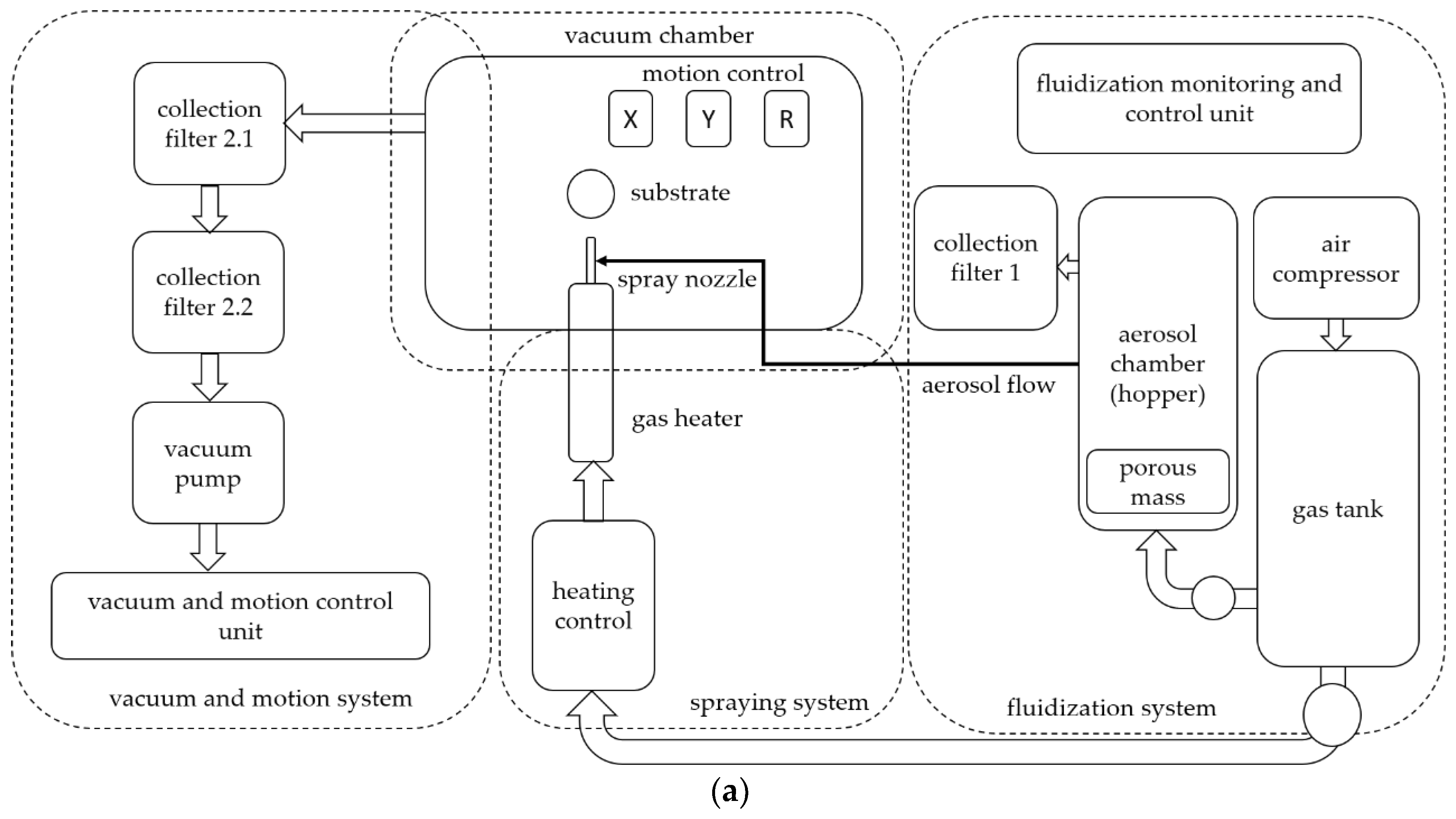
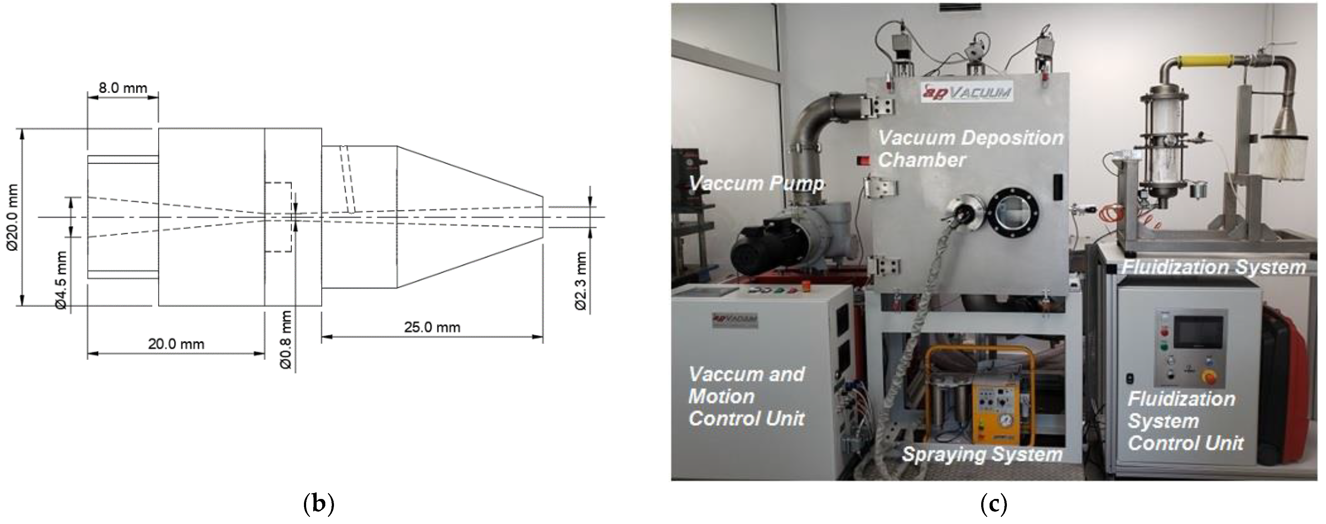
2.1. ACS Apparatus

The drawbacks of Aerosol Deposition might be overcome through the use of radial injection into the divergent part of the nozzle similar to that being used in the LPCS, as described in [24,25]. In this case, gas heating to temperatures of 500–600 °C is possible, and fluidized bed aerosol chamber parameters (gas pressure, vibration amplitude, and frequency) are controlled in the wide ranges. In the modified Aerosol Cold Spray (ACS) system (Łukasiewicz Research Network—Poznań Institute of Technology, Poznan, Poland), the fine powder contained in the particle-gas aerosol is radially sucked by the De-Laval nozzle due to a negative pressure created in the divergent part of the nozzle while propellant gas flows through the De-Laval nozzle convergent part. The effect is also magnified by the vacuum atmosphere of the deposition chamber. The propellant gas is mixed with particle-gas aerosol and accelerated in the divergent part of the nozzle with the following particle deposition onto the substrate.
The ACS apparatus (Figure 1a,c) consists of an aerosol chamber, a cold spraying system with a gun installed in a vacuum deposition chamber supplied with an X-Y stage with a sample. The vacuum and motion parameters are controlled. The ACS vacuum chamber is emptied during the deposition process using a rotary vacuum pump and a mechanical booster pump. In the aerosol chamber, the powders are mixed with carrier gas. An HA aerosol fluidized bed is formed through a vibration system and the carrier gas that is being introduced through a porous membrane. The HA ceramic powder–gas suspension that is being prepared in the aerosol chamber is delivered to a convergent part of the nozzle radially due to the difference in pressure in the nozzle injection point with that of the aerosol chamber. A circle nozzle geometry is shown in Figure 1b. The HA ceramic powder–gas suspension is fed to the divergent part of the nozzle with a powder feeding pipe and deposited onto the substrate. The particle velocities are controlled by the gun carrier gas pressure and temperature. The gas heating is performed by a gun heater of the spraying system, and the gas pressure is controlled by a flow controller of the spraying system. One can note the application of the circle nozzle shown in Figure 1a (insert) instead of the slit nozzle being applied by Akedo [18] and other researchers [19], which allows achieving a higher gas and particle velocity than that of the slit nozzle [26]. Moreover, using propellant gas (preferably nitrogen and air) at the temperature of 300–500 °C increases the gas and particle velocity up to 15–20%.

2.2. Materials and Process Parameters

The starting powders were commercially available HA with a declared particle size of 2.5 ± 0.5 μm and purity of >95% delivered by KAMB Import-Export, Warsaw, Poland. Dry milling was used to improve the uniformity of the HA powder feedstock. Particle size distribution was carried out by a Mastersizer 3000 (Malvern PANalytical, Malvern Worcestershire, UK) analyzer using the laser diffraction technique. The particle size of the HA powder ranged from 0.1 to 4.5 μm (Figure 2).
HA coatings were deposited onto Grade 5 Ti alloy (TiAl6V4) substrate with a propellant air temperature of 350 °C and a pressure of 6 bars. Preliminary grit blasting with alumina 1 mm sized particles resulted in the roughness of Ra ≈ 8.0 μm. The ACS process was carried out using the described ACS system with the pressure in the deposition chamber being about 3–5 mbar during spraying. Filtered compressed air with a pressure of about 1.6–2.0 bars was used to feed the powder particles from the aerosol chamber/hopper. A scanning speed of 5 mm/s and a stand-off distance of 10 mm were used.

2.3. Coating Sintering

Sintering of HA coatings is fundamental because the mechanical performance and the biological behavior of a coating are controlled by processes of particle consolidation and coating structure formation. As shown in [27,28], the main purposes of sintering technology are to save the coating microstructure and phase composition and control coating porosity, grain size, adhesion, and bonding strength. From this viewpoint, the application of Pressureless Sintering technology (in the electric resistance chamber furnaces) in ambient air looks reasonable because of the presence of water vapor in the sintering atmosphere that allows for saving HA Ca10(PO4)6(OH)2 phase composition. In the opposite case, the calcium-deficient hydroxyapatite phase of general formula Ca10−x(PO4)6−x(HPO4)x(OH)2−x may be formed and may decompose into BCP above 700 °C [28]. Thus, the stoichiometric chemical formula Ca10(PO4)6(OH)2 with ratio Ca/P = 1.667 should be considered as HA. Nevertheless, to achieve an effective particle bonding due to diffusion processes, the pressureless sintering of the HA coating was made at 800 °C for 60 min, which is slightly higher than the ceramic coating annealing temperature proposed by Exner et al. [29].
On the other side, the application of the Spark Plasma Sintering (SPS) process may be effective because of the short sintering time and low temperatures used. For this purpose, the ACS HA-based coating was consolidated in vacuum by SPS using an HP D 25/3 furnace (FCT Systeme, Effelder-Rauenstein, Germany). The coating was heated up to 150 °C at 50 °C/min and held at this temperature for 30 s, and then heated up to 500 °C and 800 °C at 50 °C/min and held at the sintering temperature for 30 s. The compacting pressure of 40 MPa was applied throughout the sintering process. The resulting sintering temperatures were kept in 502.5 ± 3.9 °C and 789 ± 4 °C regimes as measured by the built-in pyrometer.

2.4. Coating Structure and Property Characterization

The surface morphology and microstructure of as-sprayed and -sintered coatings were examined by Scanning Electron Microscopy (SEM) using the Quanta 250 FEG (FEI, FEI, Hillsboro, OR, USA) microscope. A low-vacuum Large Field SE Detector was used for the observations. Roughness measurements were made by a T8000RC (Jenoptik, Jena, Thüringen) profilometer with the measurement tip TKU 300 (Jenoptik, Jena, Thüringen). The crystalline structures of the coatings were characterized by X-ray diffraction (XRD) using an Empyrean (Malvern PANalytical, Malvern Worcestershire, UK) X-ray diffractometer with Cu Kα radiation; the measurement was conducted within a 20–90° 2θ diffraction angle range. The microstructure and chemical composition of the sintered compacts were observed on polished cross-sectioned surfaces by SEM and EDS. The microstructure was examined using transmission electron microscopy (TEM, FEI, Hillsboro, OR, USA) using Tecnai G2 FEG (200 kV) of foils obtained by focus ion beam polishing.
HA coating bond adhesion strength was examined by tensile tests in accordance with ISO 13779-4 Standard on the samples of 25 mm diameter. Epoxy adhesive Locite EA 9480 with a declared tensile strength of 44 MPa was used as binding media. The tensile strength tests were conducted on INSTRON 4483 testing machine with 1.2–1.5 mm/min strain rate.

3. Results and Discussion

3.1. Structure and Microstructure Analysis

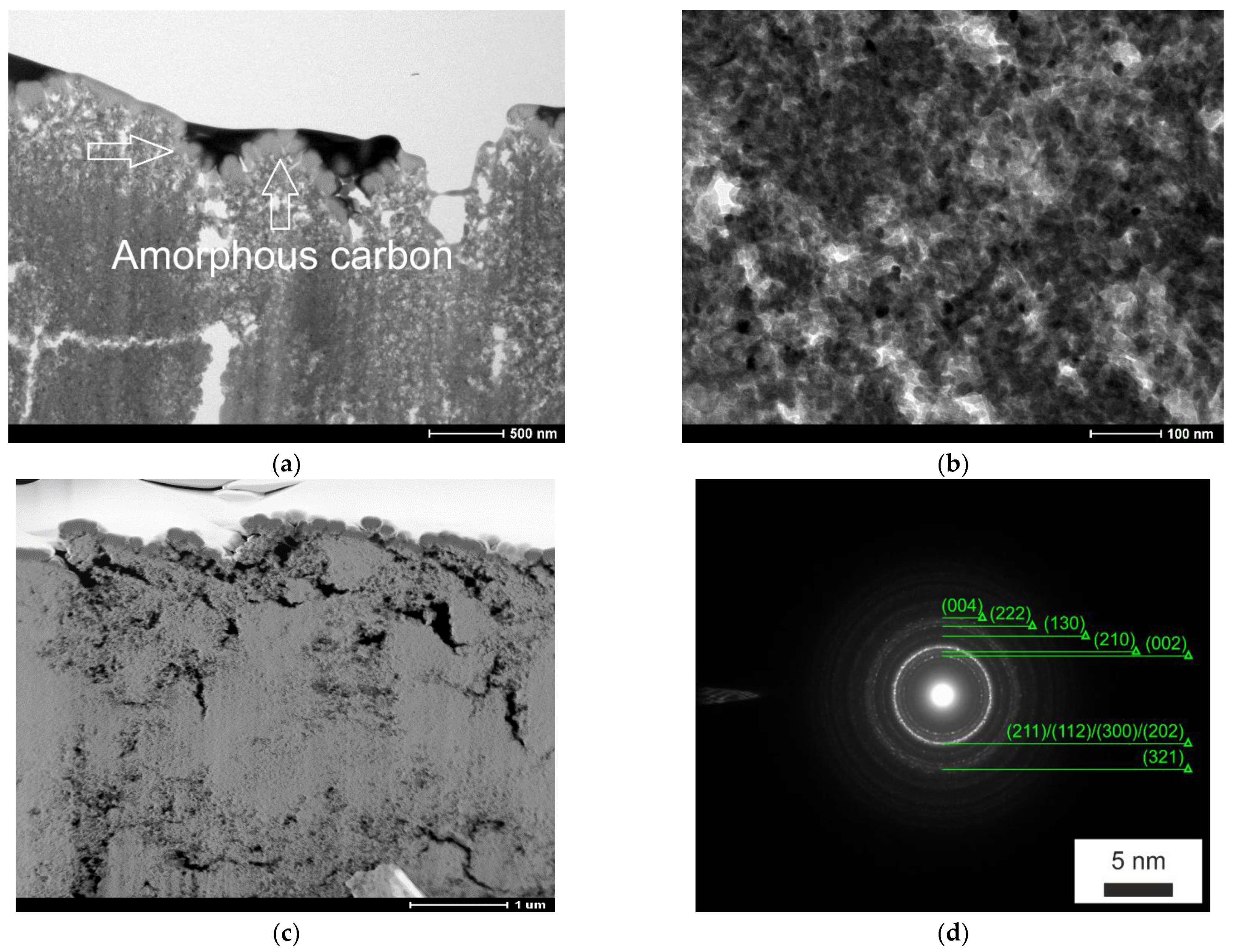
3.1.1. Cross-Sectional Coating Microstructure Observations Using Light Microscopy, Scanning and Transmission Electron Microscopy

The cross-section light and SEM micrographs of the HA coatings fabricated at the above-mentioned aerosol parameters are shown in Figure 3 and Figure 4. The HA coatings display heterogenous compacted layers of HA particles consisting of relatively dense particle aggregates, micro-cracks, and pores at the layers’ interface, and coating surface micro-peaks and valleys, whose geometry is similar to that of a substrate surface. From the cross-section SEM micrographs (Figure 4), it can be seen that the thickness of HA coatings is ≈20–30 μm. Light micrographs (Figure 3) show the cross-section morphology of the HA-coating–substrate interface, which is characterized with micro-peaks of irregular shape obtained using grit blasting. This allows for achieving an interlocking effect of HA coating adhesion.
It is evident from the SEM images of cross-sections (Figure 4a–c) that the HA layers’ interface comprises micro-cracks and pores of different sizes. A possible reason for their origination may be internal stresses within the coating after the spraying process as well as low particle cohesion due to the deposition of agglomerated particles. Additionally, it can be seen from a coating–substrate examination that the coating exhibits a slight debonding from the substrate, which occurred during the mounting of the samples.
TEM examination of coating cross-section foils allows evaluating the structure formation features at high magnifications. The coating samples were covered by ≈100 nm amorphous carbon layer before observations (Figure 5a, arrows). The results (Figure 5) reveal the following coating specific features:
  • The crystalline structure of HA particles is preserved due to the cold spraying regime of coating structure formation, as seen on the Selected Area Electron Diffraction (SAED) micrograph (Figure 5d), crystal planes correspond to hydroxyapatite phase;
  • Particle fragmentation due to high-velocity impact (Figure 5b) resulting in the presence of particle fragments of 10–20 nm size;
  • Small grain size of the HA coating both in the subsurface and coating core (Figure 5b);
  • Pores of various sizes are seen (Figure 5c), and larger pores are seen on the coating’s surface, indicating a lower effect of the hammering effect [19] on the newly deposited particles.

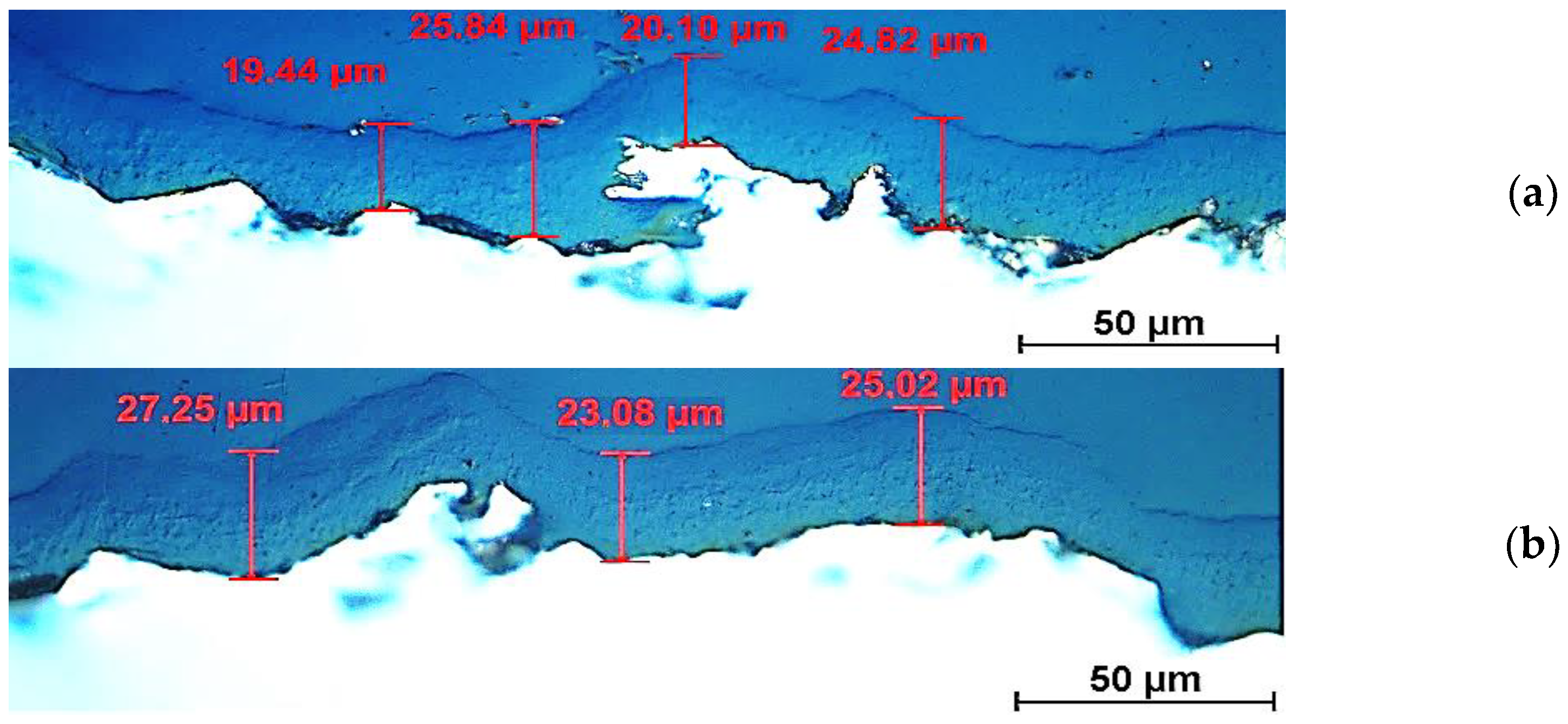
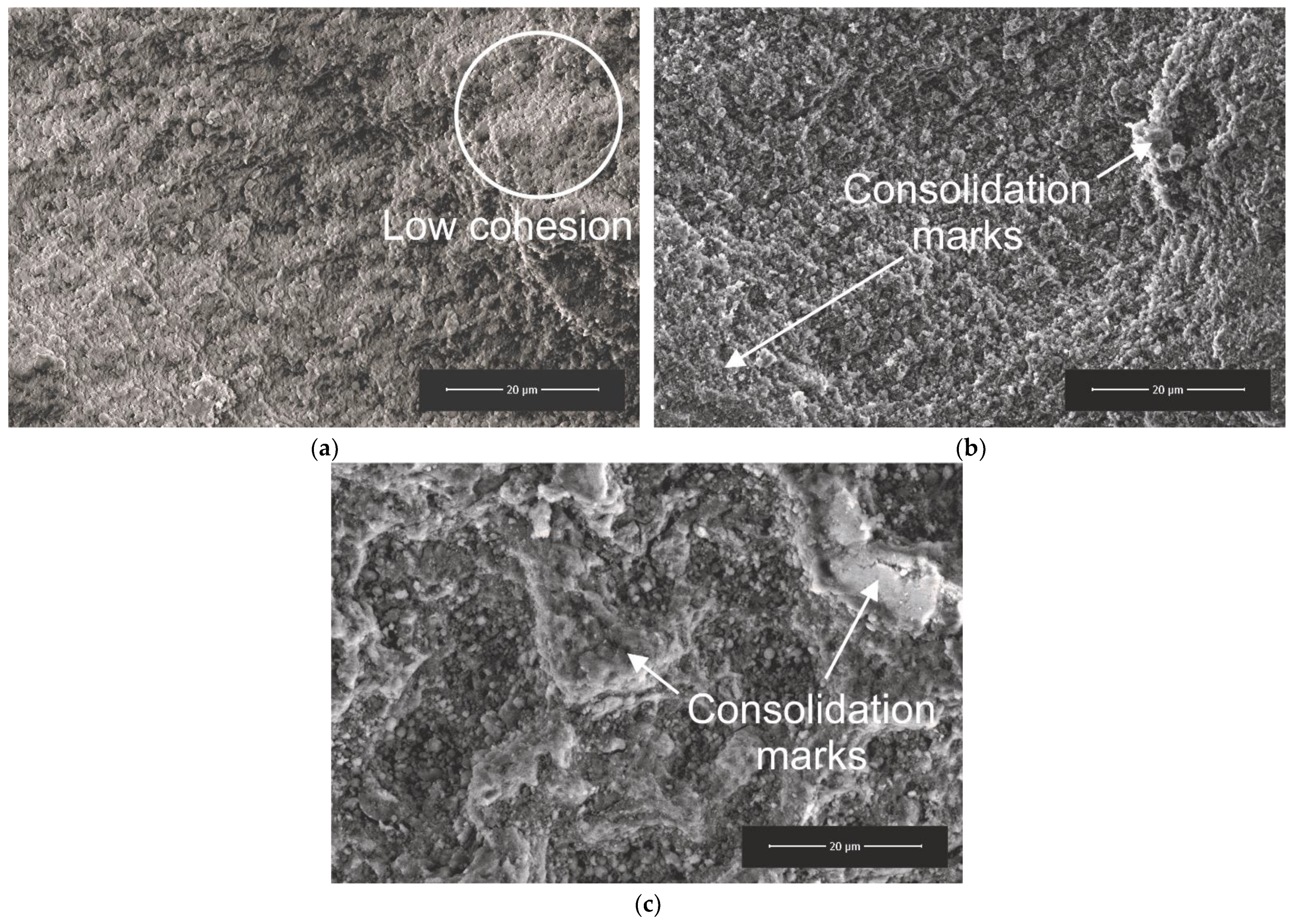
3.1.2. Effects of Post-Treatment Assessed by Surface Observations by Scanning Electron Microscopy and Profilometry

SEM micrographs of the HA coating surface topography are shown in Figure 6. The dispersed surface morphology after spraying is characterized by HA particle agglomerate formation with separate micropeaks and high porosity (Figure 6a). Pressureless Sintering changes the coating surface topography by bonding and shrinkage process development (Figure 6b). The coating topography after SPS sintering shows valleys of 10–15 µm (Figure 6c). The coatings exhibit 10–20 µm sized pits and protrusions on their surfaces, indicating non-uniform sintering and densification of the separate areas (shown by arrows). The roughness of these areas is smaller than that of neighboring ones. This needs to be taken into account because it is well known that surface roughness is critical in allowing cell growth because the surfaces influence protein interaction, which determines subsequent cell adhesion [30]. The SEM micrograph of the cross-section of as-sprayed HA coating (Figure 4b,c) reveals the presence of some cracks and pores, while SPS results in increased coating consolidation and possible microcracks’ healing (Figure 6c). Similar results were observed for as-sprayed and post-heat-treated HA-based coating in [31].
A comparison of substrate and HA coating roughness (Ra) (Table 1) demonstrates that the roughness difference between the substrate and the coating is negligible, while the application of sintering following this results in coating roughness falling up to Ra = 3.0–3.5 µm. The decrease in roughness also suggests that the densification of the coatings took place.

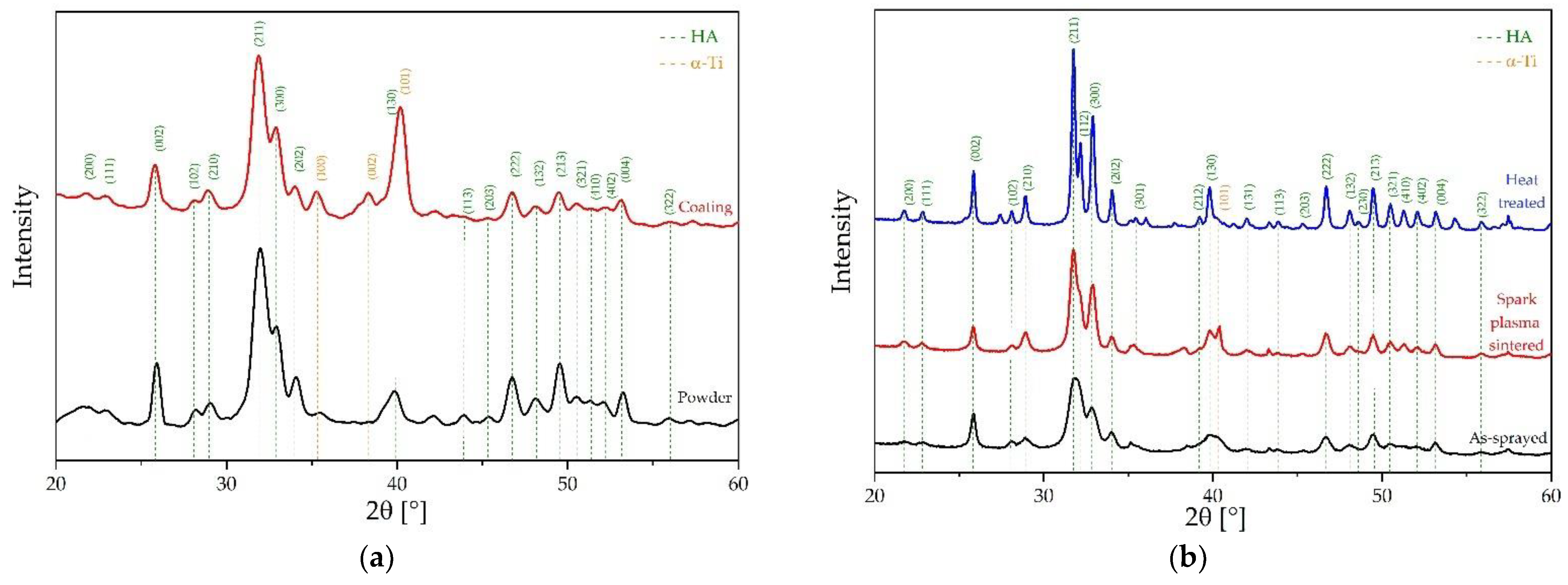
3.1.3. Structural Impact of Coating Process and Post-Treatment Analyzed Using X-ray Diffraction (XRD) Supported by Electron Dispersive Spectroscopy (EDS)

The heat treatment of HA coatings at relatively short holding times allows the sintering of HA particles at the conditions that hinder grain growth and decomposition of HA and improve the coating adhesion/bonding strength and toughness [31]. Figure 7 shows the X-ray diffraction pattern for the HA powder, as-sprayed (Figure 7a), and pressureless sintered coatings. For the sake of briefness, a smaller 20–60° diffraction angle range was presented. The structure of the initial powder consists mainly/only of the hydroxyapatite phase. No other phases were created as a result of the spraying process. Additional peaks that were found (at 35.24°; 38.60°; 39.95°) as a result of the spraying process belonged to the Hydroxyapatite/Calcium Oxide Phosphate family (based on ICDD: 00-024-0033) and titanium alloy (ICDD: 04-002-2539) substrate. The obtained data reveal that the spraying of HA powder with propellant air at the temperature of 300 °C does not result in a considerable Ca10(PO4)6(OH)2 decomposition. Only a slight broadening of the diffraction peaks is seen due to the deformation and fracture of HA crystals. On the contrary, in the plasma as-sprayed coating, a small number of impurity phases were identified between 30.5° and 31.7° by X-ray diffraction [31].
The post-spraying pressureless heat treatment at 800 °C for 60 min effectively consolidates HA particles and facilitates structural integrity of the HA coating by recrystallization of HA crystals, which results in sharper peaks of the X-ray diffraction pattern, as shown in Figure 7b.
SPS of HA coating facilitates an intensive consolidation process (bright areas on SEM micrograph in Figure 6c) and leads to the preferable formation of Ca10(PO4)6(OH)2 phase (Figure 5b). Some Ti peaks are visible in the X-ray diffraction pattern, which is the effect of the Ti alloy substrate.
As can be seen in Table 2, regarding the ratio of Ca/P, the elemental composition (at. %) was found to be 1.47 as compared to theoretical Ca/P = 1.67 [32]. However, the X-ray diffraction pattern (Figure 7a), as well as the SAED pattern (Figure 5d), did not show the observable presence of other calcium phosphate compounds. The possible reason for that is the uncertainty of the EDS measurement or the presence of a calcium-deficient form of hydroxyapatite [33].

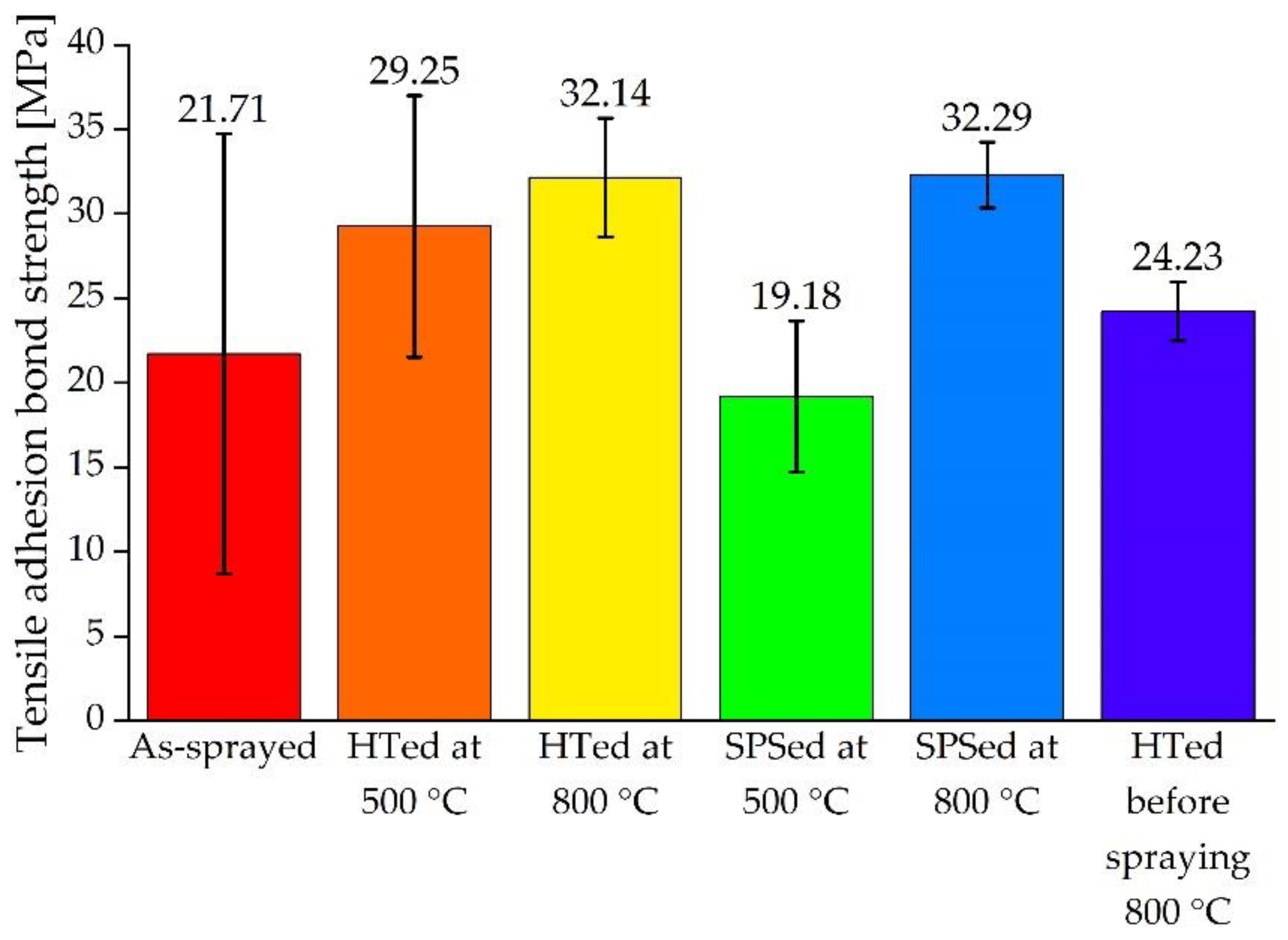
3.2. Adhesion Strength of HA Coatings

The values of the tension adhesion strength of HA coatings defined in accordance with ISO 13779-4 are shown in Table 3 and the diagram in Figure 8. Various regimes of heat treatment of both coating and substrate (Table 3) were applied to define the influence of particle consolidation during sintering and Ti alloy substrate surface modification (oxide layer formation) on the coating adhesion.
As-sprayed coatings have shown an average adhesion strength of about 22 MPa. However, the results exhibit a very high variation. The reason for such property scattering may be the lack of uniformity of the generated aerosol composition (high content of agglomerated particles) and the unstable particle consolidation process during cold spraying. Coating sintering at 500 °C increases the adhesion strength, while the variation remains high. Increasing the sintering temperature up to 800 °C using both pressureless heat treatment and SPS sintering improves the coating adhesion strength over the 30 MPa threshold and decreases the scatter of results significantly. These data are in line with microstructure examination results of HA particle consolidation and facilitation of structural integrity of the HA coating due to enhanced diffusion-controlled processes. From this viewpoint, an increase in coating adhesion strength might be linked to HA crystallite growth [34] and the closing of micro-pores in coatings [35]. The annealing of Ti alloy substrate (regime 6, Table 3) results in the diminishing of the adhesion strength variation layer up to 1.75 MPa due to the presence of TiO2 on the substrate.
The results contrast with the results obtained as a result of the heat treatment of other thermally sprayed hydroxyapatite coatings [15,31]; however, cold sprayed (solid-state deposited) coatings tend to present an increase in adhesion strength after heat treatment (as shown in conducted experiments) due to intense diffusion. The SPS method has an additional advantage for the improvement in coatings adhesion—the heat is generated at the interface areas (particle–particle and substrate–coating areas), improving both cohesion and adhesion of the coatings in much shorter sintering time than HT [36].
The achieved combination of relatively [6] high adhesion bond strength, preserved crystal structure, and fast coating thickness buildup suggests that ACS sintering is a very attractive surface coating technology compared to the other technologies [13,15].

4. Conclusions

The spraying process using the ACS system led to the formation of hydroxyapatite coating of 20–30 µm thicknesses. The coatings exhibited nano-scale porosity, with larger pores closer to the coating’s surface, which can be attributed to the lesser impact of the hammering effect and the presence of agglomerated particles in the spraying stream. Multiple cracks perpendicular to the spraying direction were visible, signifying hindered cohesion between subsequent layers of the coating. No increase in adhesion strength was observed after SPS at 500 °C. Heat treatment at 500 °C led to an increase of about ≈30% in adhesion strength, but a high variation in the results still remained. The increase in SPS and HT temperature to 800 °C increased the adhesion strength over 30 MPa and decreased the variation in results. Further research will be conducted in the field of powder material preparation for ACS, process parameters optimalization, and studies of bioactivity and possible pathogen responses to the coating surface.

5. Patents

The research results presented in this manuscript are protected by intellectual property in the Republic of Poland on the basis of patent application No. P.435568.

Author Contributions

Conceptualization, V.L.; Data Curation, J.S.-C.; Formal Analysis, M.W. and G.K.; Funding Acquisition, V.L. and J.S.-C.; Investigation, G.K., M.W., A.E. and J.S.-C.; Methodology, V.L.; Project Administration, J.S.-C.; Resources, J.S.-C. and A.E.; Supervision, R.G.M. and J.J.; Validation, V.L., R.G.M. and J.J.; Visualization, M.W.; Writing—Original Draft Preparation, V.L., A.E.; Writing—Review and Editing, G.K. All authors have read and agreed to the published version of the manuscript.

Funding

Investigations were conducted by The Polish National Centre for Research and Development within project no. POIR.04.01.04-00-0074/17 named “Comprehensive development and preparation for the implementation of innovative implant solutions in the treatment of animals, surgical instruments for their implantology and biodegradable surgical thread for veterinary medicine” Action 4.1 “Research and Development”, Subaction 4.1.4 “Application projects” Operational Program Smart Growth 2014–2020, co-financed from the European Regional Development Fund.

Institutional Review Board Statement

Not applicable.

Informed Consent Statement

Not applicable.

Data Availability Statement

Not applicable.

Conflicts of Interest

The authors declare no conflict of interest.

References

  1. Surmenev, R.A.; Surmeneva, M.A. A critical review of decades of research on calcium phosphate–based coatings: How far are we from their widespread clinical application? Curr. Opin. Biomed. Eng. 2019, 10, 35–44. [Google Scholar] [CrossRef]
  2. Heimann, R.B. Plasma-sprayed hydroxylapatite-based coatings: Chemical, mechanical, microstructural, and biomedical properties. J. Therm. Spray Technol. 2016, 25, 827–850. [Google Scholar] [CrossRef] [Green Version]
  3. Arcos, D.; Vallet-Regí, M. Substituted hydroxyapatite coatings of bone implants. J. Mater. Chem. B 2020, 8, 1781–1800. [Google Scholar] [CrossRef] [PubMed]
  4. Jaafar, A.; Hecker, C.; Árki, P.; Joseph, Y. Sol-gel derived hydroxyapatite coatings for titanium implants: A review. Bioengineering 2020, 7, 127. [Google Scholar] [CrossRef] [PubMed]
  5. Ritwik, A.; Saju, K.K.; Vengellur, A.; Saipriya, P.P. Development of thin-film hydroxyapatite coatings with an intermediate shellac layer produced by dip-coating process on Ti6Al4V implant materials. J. Coat. Technol. Res. 2022, 19, 597–605. [Google Scholar] [CrossRef]
  6. Beig, B.; Liaqat, U.; Niazi, M.F.K.; Douna, I.; Zahoor, M.; Niazi, M.B.K. Current challenges and innovative developments in hydroxyapatite-based coatings on metallic materials for bone implantation: A review. Coatings 2020, 10, 1249. [Google Scholar] [CrossRef]
  7. Fadli, A.; Mulya, N.; Pane, K.B.; Pratama, A. Effect of Solid Loading and Dipping Time on Microstructure and Shear Strength of Hydroxyapatite Coatings Deposited via Dip Coating Technique. In Proceedings of the IOP Conference Series: Earth and Environmental Science, Yogyakarta, Indonesia, 4–5 August 2021. [Google Scholar]
  8. Surmenev, R.A.; Ivanova, A.A.; Epple, M.; Pichugin, V.F.; Surmeneva, M.A. Physical principles of radio-frequency magnetron sputter deposition of calcium-phosphate-based coating with tailored properties. Surf. Coat. Technol. 2021, 413, 127098. [Google Scholar] [CrossRef]
  9. Liguori, A.; Gualandi, C.; Focarete, M.L.; Biscarini, F.; Bianchi, M. The pulsed electron deposition technique for biomedical applications: A review. Coatings 2019, 10, 16. [Google Scholar] [CrossRef] [Green Version]
  10. Duta, L. In vivo assessment of synthetic and biological-derived calcium phosphate-based coatings fabricated by pulsed laser deposition: A review. Coatings 2021, 11, 99. [Google Scholar] [CrossRef]
  11. Safavi, M.S.; Walsh, F.C.; Surmeneva, M.A.; Surmenev, R.A.; Khalil-Allafi, J. Electrodeposited hydroxyapatite-based biocoatings: Recent progress and future challenges. Coatings 2021, 11, 110. [Google Scholar] [CrossRef]
  12. Taranu, B.-O.; Ianasi, P.; Rus, S.F.; Bucur, A.I. Simultaneous precipitation and electrodeposition of hydroxyapatite coatings at different temperatures on various metal substrates. Coatings 2022, 12, 288. [Google Scholar] [CrossRef]
  13. He, D.; Zhang, X.; Liu, P.; Liu, X.; Chen, X.; Ma, F.; Li, W.; Zhang, K.; Zhou, H. Effect of hydrothermal treatment temperature on the hydroxyapatite coatings deposited by electrochemical method. Surf. Coat. Technol. 2021, 406, 126656. [Google Scholar] [CrossRef]
  14. Ghadami, F.; Saber-Samandari, S.; Rouhi, G. The Effects of Substrates’ Materials on Hardness, Creep, and Residual Stress of the Hydroxyapatite Coating, Deposited by HVOF Method. In Proceedings of the 27th National and 5th International Iranian Conference on Biomedical Engineering (ICBME), Tehran, Iran, 26–27 November 2020; pp. 154–158. [Google Scholar]
  15. Tiwari, S.; Mishra, S.B. Post annealing effect on corrosion behavior, bacterial adhesion, and bioactivity of LVOF sprayed hydroxyapatite coating. Surf. Coat. Technol. 2021, 405, 126500. [Google Scholar] [CrossRef]
  16. Ratha, I.; Datta, P.; Balla, V.K.; Nandi, S.K.; Kundu, B. Effect of doping in hydroxyapatite as coating material on biomedical implants by plasma spraying method: A review. Ceram. Int. 2021, 47, 4426–4445. [Google Scholar] [CrossRef]
  17. Vilardell, A.M.; Cinca, N.; Dosta, S.; Cano, I.G.; Guilemany, J.M. Feasibility of using low pressure cold gas spray for the spraying of thick ceramic hydroxyapatite coatings. Int. J. Appl. Ceram. Technol. 2019, 16, 221–229. [Google Scholar] [CrossRef] [Green Version]
  18. Akedo, J. Aerosol deposition of ceramic thick films at room temperature: Densification mechanism of ceramic layers. J. Am. Ceram. Soc. 2006, 89, 1834–1839. [Google Scholar] [CrossRef]
  19. Hanft, D.; Exner, J.; Schubert, M.; Stöcker, T.; Fuierer, P.; Moos, R. An overview of the aerosol deposition method: Process fundamentals and new trends in materials applications. J. Ceram. Sci. Technol. 2015, 6, 147–182. [Google Scholar] [CrossRef]
  20. Cho, M.Y.; Lee, D.W.; Kim, I.S.; Kim, W.J.; Koo, S.M.; Lee, D.; Kim, Y.H.; Oh, J.M. Evaluation of structural and mechanical properties of aerosol-deposited bioceramic films for orthodontic brackets. Ceram. Int. 2019, 45, 6702–6711. [Google Scholar] [CrossRef]
  21. Yan, C.; Ma, G.; Chen, A.; Chen, Y.; Wu, J.; Wang, W.; Yang, S.; Shi, Y. Additive manufacturing of hydroxyapatite and its composite materials: A review. J. Micromechanics Mol. Phys. 2020, 5. [Google Scholar] [CrossRef]
  22. Han, Y.-H.; Gao, R.; Bajpai, I.; Kim, B.-N.; Yoshida, H.; Nieto, A.; Son, H.-W.; Yun, J.; Jang, B.-K.; Jhung, S.; et al. Spark plasma sintered bioceramics–from transparent hydroxyapatite to graphene nanocomposites: A review. Adv. Appl. Ceram. 2020, 119, 57–74. [Google Scholar] [CrossRef]
  23. Anselmi-Tamburini, U. Spark Plasma Sintering. In Encyclopedia of Materials: Technical Ceramics and Glasses; Pomeroy, M., Ed.; Elsevier: Oxford, UK, 2021; pp. 294–310. [Google Scholar]
  24. Mishra, T.P.; Singh, R.; Mücke, R.; Malzbender, J.; Bram, M.; Guillon, O.; Vaßen, R. Influence of process parameters on the aerosol deposition (AD) of yttria-stabilized zirconia particles. J. Therm. Spray Technol. 2021, 30, 488–502. [Google Scholar] [CrossRef]
  25. Leshchynsky, V.; Garbiec, D.; Sulej-Chojnacka, J.; Elseddawy, A.; Bajek, A. Aerosol Cold Spray Powder Consolidation of Hydroxyapatite Coatings and its Properties. Presented at the EuroPM 2019, Maastricht, Germany, 13–16 October 2019. [Google Scholar]
  26. Maev, R.G.; Leshchynsky, V. Cold Gas Dynamic Spray; CRC Press: Boca Raton, FL, USA, 2016. [Google Scholar]
  27. Hwang, C.; Yun, J. Flash sintering of hydroxyapatite ceramics. J. Asian Ceram. Soc. 2020, 9, 1–8. [Google Scholar] [CrossRef]
  28. Champion, E. Sintering of calcium phosphate bioceramics. Acta Biomater. 2012, 9, 5855–5875. [Google Scholar] [CrossRef] [PubMed]
  29. Exner, J.; Nazarenus, T.; Hanft, D.; Kita, J.; Moos, R. What happens during thermal post-treatment of powder aerosol deposited functional ceramic films? Explanations based on an experiment-enhanced literature survey. Adv. Mater. 2020, 32, 1908104. [Google Scholar] [CrossRef] [PubMed]
  30. Li, D.; Gong, Y.; Chen, X.; Zhang, B.; Zhang, H.; Jin, P.; Li, H. Room-temperature deposition of hydroxyapatite/antibiotic composite coatings by vacuum cold spraying for antibacterial applications. Surf. Coat. Technol. 2017, 330, 87–91. [Google Scholar] [CrossRef]
  31. Singh, A.; Singh, G.; Chawla, V. Characterization of vacuum plasma sprayed reinforced hydroxyapatite coatings on Ti–6Al–4V alloy. Trans. Indian Inst. Met. 2017, 70, 2609–2628. [Google Scholar] [CrossRef]
  32. Singh, S.; Prakash, C.; Singh, H. Deposition of HA-TiO2 by plasma spray on β-phase Ti-35Nb-7Ta-5Zr alloy for hip stem: Characterization, mechanical properties, corrosion, and in-vitro bioactivity. Surf. Coat. Technol. 2020, 398, 126072. [Google Scholar] [CrossRef]
  33. Mohammadi, M.; Tulliani, J.-M.; Montanaro, L.; Palmero, P. Gelcasting and sintering of hydroxyapatite materials: Effect of particle size and Ca/P ratio on microstructural, mechanical and biological properties. J. Eur. Ceram. Soc. 2021, 41, 7301–7310. [Google Scholar] [CrossRef]
  34. Sun, W.; Tan, A.W.-Y.; Wu, K.; Yin, S.; Yang, X.; Marinescu, I.; Liu, E. Post-process treatments on supersonic cold sprayed coatings: A review. Coatings 2020, 10, 123. [Google Scholar] [CrossRef] [Green Version]
  35. Azis, S.A.A.; Kennedy, J.; Cao, P. Effect of annealing on microstructure of hydroxyapatite coatings and their behaviours in simulated body fluid. Adv. Mater. Res. 2014, 922, 657–662. [Google Scholar] [CrossRef]
  36. Ito, K.; Ogawa, K. Effects of spark-plasma sintering treatment on cold-sprayed copper coatings. J. Therm. Spray Technol. 2014, 23, 104–113. [Google Scholar] [CrossRef]
Figure 1. Aerosol Cold Spray (ACS) system for ceramic powder deposition: (a) ACS schematics; (b) spraying De-Laval nozzle geometry; (c) ACS system view.
Coatings 12 00535 g001aCoatings 12 00535 g001b
Figure 2. Particle distribution of HA powder.
Coatings 12 00535 g002
Figure 3. Light micrographs of HA coatings made by Aerosol Cold Spraying. (a) higher roughness area (b) lower roughness area.
Coatings 12 00535 g003
Figure 4. SEM micrographs at various magnifications (ac) of HA coatings made by Aerosol Cold Spraying.
Coatings 12 00535 g004
Figure 5. TEM micrographs of HA coating structure: (a) Bright Field (BF) mode subsurface micrograph, (b) high magnification BF mode micrograph, (c) Dark Field (DF) mode micrograph, indicating pores in subsurface layer, (d) SAED pattern of the coating.
Coatings 12 00535 g005
Figure 6. SEM micrographs of HA coating surface topography at ×5000 magnification (a) after spraying, (b) Pressureless Sintering, (c) after SPS sintering.
Coatings 12 00535 g006
Figure 7. X-ray diffraction pattern of HA: (a) powder and coating as-sprayed, (b) coating in as-sprayed, heat-treated, spark-plasma-sintered state at 800 °C.
Coatings 12 00535 g007
Figure 8. Tensile adhesion bond strength results of HA coatings.
Coatings 12 00535 g008
Table 1. HA coated surface roughness.
As-CoatedPressureless SinteringSPS
Sample
Number
Roughness
Ra
µm
Roughness
Ra
µm
Roughness
Ra
µm
17.533.843.16
27.393.522.73
38.073.123.11
Average7.663.493.0
Table 2. HA as-sprayed coating chemical composition measured by EDS.
ElementWt.%At%
P25.2131.68
Ca47.9446.55
Ti26.0221.14
Table 3. The tensile adhesion strength of HA coatings.
No.State of the CoatingAverage Adhesion
Strength
MPa
Adhesion Strength
Variation
MPa
1As-sprayed21.7113.02
2Pressureless sintered at 500 °C29.257.74
3Pressureless sintered at 800 °C32.143.51
4SPSed at 500 °C19.184.47
5SPSed at 800 °C32.291.94
6HTed of Ti alloy substrate at 800 °C before spraying 24.231.75
Publisher’s Note: MDPI stays neutral with regard to jurisdictional claims in published maps and institutional affiliations.

