Article

Preparation and Luminescence Properties of PVDF/ZnS:Mn Flexible Thin-Film Sensors

1
School of Materials Science and Engineering, Jiangsu University, Zhenjiang 212013, China
2
School of Mechanical and Intelligent Manufacturing, Jiujiang University, Jiujiang 332005, China
*
Author to whom correspondence should be addressed.
Coatings 2022, 12(4), 449; https://doi.org/10.3390/coatings12040449
Submission received: 27 February 2022 / Revised: 20 March 2022 / Accepted: 24 March 2022 / Published: 25 March 2022
(This article belongs to the Special Issue Thick and Thin Films for Functional Device Applications)

Abstract

:
Flexible luminescent thin-film sensors have attracted widespread attention for their potential applications in biomedical detection, structural health detection, and smart wear. In this work, PVDF/ZnS:Mn flexible luminescent thin-film sensors were fabricated using electro-assisted 3D-printing techniques. The interaction and influence of PVDF thin film and ZnS:Mn were studied. The mechanism through which the PVDF matrix and ZnS:Mn particles affects the luminescence of the flexible thin-film sensor were investigated. The results demonstrate that the ZnS:Mn luminescent particles in PVDF thin films can promote the formation of the β-phase in the PVDF thin films. The mechano-luminesce spectra of the PVDF/ZnS:Mn composite thin film is consistent with the photoluminescence spectra, both of which exhibit yellow light with a wavelength of 580 nm. Mn entering the ZnS lattice increases the number of effective luminescent centres. Because of the double piezoelectric field, when the Mn content of ZnS:Mn is 4 at.% and PVDF films contain 3 wt.% ZnS:Mn particles, the PVDF/ZnS:Mn flexible thin-film sensors demonstrate excellent mechano-luminescence performance.

1. Introduction

The phenomenon of luminescence refers to the radiation phenomenon in which a substance absorbs other forms of energy and converts that energy into visible light when it is stimulated by light, voltage, or force. Sensors based on the principle of luminescence have broad prospects in biomedical detection, structural health detection, smart wear, and air quality monitoring; many scholars have conducted extensive research in this area [1,2,3,4,5,6,7]. Chandra [8] reported research on the application of mechano-luminescent (ML) materials in the field of impact luminescence and proposed a new type of mechano-luminescent stress sensor under high pressure. Kim [9] developed a new torque luminescent sensor. The signal of the sensor is transmitted in a noncontact manner, which can accurately measure the torque according to the intensity of luminescence under torsion.
The key to improving the luminescence of the sensor is the material. ZnS is a typical II-VI semiconductor material, which has good ferromagnetic, piezoelectric, photoelectric, and photosensitive properties. Owing to its high specific surface area and quantum size effect, ZnS has been a good choice to be the matrix material of multicolor phosphors [10,11,12]. Sm3+, Cu2+, and Ni2+ have introduced doping into ZnS, resulting in additional energy levels in the band gap, which changes the microstructure, defects, and energy band properties of the ZnS matrix, and the optical properties of ZnS will be improved by this ion doping. Generally speaking, ZnS-doped Sm3+ emits red light [13], doped Ni2+ emits green light [14], and doped Mn2+ emits orange-yellow light [15]. In addition, Tan [16] confirmed that wet chemistry can be used to successfully dope Sm3+ into ZnS. They found that the photoluminescence intensity of ZnS increased with the doping amount and reached a maximum at 3% doping, after which the luminescence intensity began to decrease again. In addition, this phenomenon is attributed to the energy transfer between Sm ions. Yang [17] found that ZnS nanoparticles doped with Ni2+ had a strong green emission band at 520 nm when the optimal doping molar ratio of Ni2+ was 0.3% and that the fluorescence quantum yield was significantly higher than that of pure ZnS crystals.
At present, most luminescent thin-film sensors are planar, opaque, and inflexible, and the structure of sensing devices is complex and brittle. Especially for mechanoluminescent sensors, after being subjected to mechanical stress and tensile action, they are prone to damage and fracture, which makes it difficult to meet the application requirements of flexible devices in the fields of electronic skin, non-destructive testing, stress imaging, and anti-information-counterfeiting labels. To obtain flexible luminescent materials, scholars mostly choose ZnS-based luminescent materials mixed with high polymer materials that can automatically recover over time after being forced to emit light [18,19]. Jeong mixed ZnS:Cu luminescent particles with polydimethylsiloxane (PDMS) and prepared a flexible luminescent material with wind as its power source [20]. Sabira et al. provided a method for preparing polyvinylidene fluoride (PVDF)/doped ZnS nanocomposite films. Under mechanical stress or during a water bath ultrasound, bright light can be observed being stably emitted by the films [21,22]. Compounding luminescent particles with a flexible matrix can improve the flexibility and expand the application range of mechanical luminescent materials. However, most of the research on the improvement of mechanical luminescent properties is still focused on luminescent particles themselves, and the promotion of flexible matrices to improve mechanical luminescent properties has not been thoroughly discussed [23,24].
In this study, PVDF/ZnS:Mn flexible thin-film sensors were prepared using electro-assisted 3D-printing techniques. The interaction and influence of PVDF thin film and ZnS:Mn were studied. The mechanism through which the PVDF matrix affects the mechano-luminescence of composite films and the luminescence properties of the PVDF/ZnS:Mn flexible thin-film sensor were investigated.

2. Materials and Methods

ZnS:Mn particles were prepared via a high-temperature solid-phase sintering method using ZnS (ZnS, 99.99%), manganese carbonate (MnCO3, 99.95%), anhydrous ethanol (C2H5OH, 99.70%), and high-purity nitrogen (N2, 99.99%) as raw materials. The MnCO3 and ZnS mixtures containing 1 at.%, 2 at.%, 3 at.%, 4 at.%, 5 at.%, and 6 at.% Mn2+ were prepared, respectively. The raw material was weighed in proportion. The slurry was made by mixing raw materials and a certain amount of anhydrous ethanol. After being dried at 80 °C to remove the absolute ethanol, the dried mixture was placed in a tube furnace, sintered at 1050 °C for 4 h, and the heating rate was 5 °C/min. N2 was injected into the tube throughout the sintering process at a gas-flow rate of 20 mL/min. Samples were taken and placed in an agate mortar until the high-temperature solid sintering was complete. The ZnS:Mn samples containing a different Mn2+ doping amount were obtained. Then, they were ground and sieved into fine particles.
Polyvinylidene fluoride (PVDF, molecular weight 370,000, French Acoma) with a mass fraction of 16% was dissolved in N,N-dimethylacetamide (DMAC, 99.0%) solvent, and the resulting solution is called a PVDF mixed solution. The PVDF mixed solution was ultrasonicated for 30 min so that the PVDF powder in the solvent was completely dissolved and the mixed solution was uniform and transparent. The ZnS:Mn particles were added into the mixed solution by 1 wt.%, 2 wt.%, and 3 wt.%, respectively. They were dispersed by magnetic stirring for 2 h. A PVDF-printing solution containing ZnS:Mn particles was obtained.
PVDF/ZnS:Mn composite thin films were prepared using electro-assisted 3D-printing techniques. As shown in Figure 1, the prepared printing solution was placed in a syringe, and the syringe was fixed on the nozzle of the 3D printer. The flat-headed steel nozzle tip was formed with an inner diameter of 0.41 mm. It was assisted by a 6 kV DC voltage between the metal jig and copper plate. The temperature of the heated plate was set at 60 °C, and the distance between the printing needle and the printed bottom plate was set at 2 mm. The running speed of the printer was set to 15 mm/s. A 20 mm × 20 mm PVDF/ZnS:Mn composite film with 70 layers was obtained by layer-by-layer printing. After printing, the PVDF/ZnS:Mn thin film was coated with two layers of tape-like PET film as a protective layer, and the sensor was obtained.
The microstructures of the samples were examined using an X-ray diffractometer (XRD, D/max2500PC, Rigaku Co., Tokyo, Japan) and a field-emission scanning electron microscope (SEM, FEINovaNano450, FEI Company, Hillsboro, OR, USA). The β-phase content of the film was analyzed by a Fourier transform infrared spectrometer (Nicolet 6700, Thermo Fisher Scientific, MA, USA); the ATR mode is used for measurement. The ultraviolet absorption spectra of the samples were measured by a UV-visible spectrophotometer (UV2600, Shimadzu, Kyoto, Japan). An advanced steady-state transient fluorescence measurement system (PTI QuantaMasterTM 4CW, Horiba, Kyoto, Japan) was used to examinate the photo-luminescence (PL) properties of the sample, and it was excited by a laser pulse source with a wavelength of 320 nm. The different pressures applied to the sensor were detected using a pressure sensor (NLB-50, Wilo, Beijing, China), and the wavelength of mechano-luminescent of the sensor was measured using an optical fibre spectrometer (EU2000, Hangzhou Tongshang photoelectric Co., Ltd., Hangzhou, China). The mechano-luminescent (ML) intensity of the sensors was expressed by measuring the luminous flux of unit section with a photon detector (C9692, Hamamatsu, Shizuoka-ken, Japan).

3. Results and Discussions

3.1. Microstructure of PVDF/ZnS:Mn Thin Films and ZnS:Mn Particles

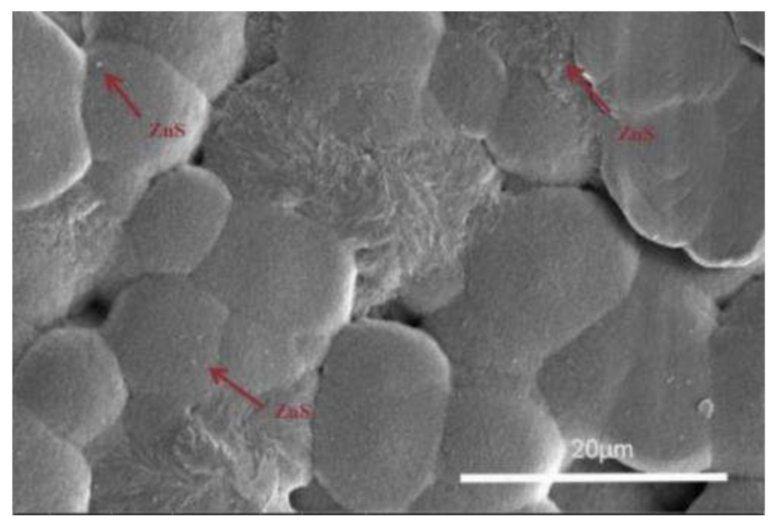
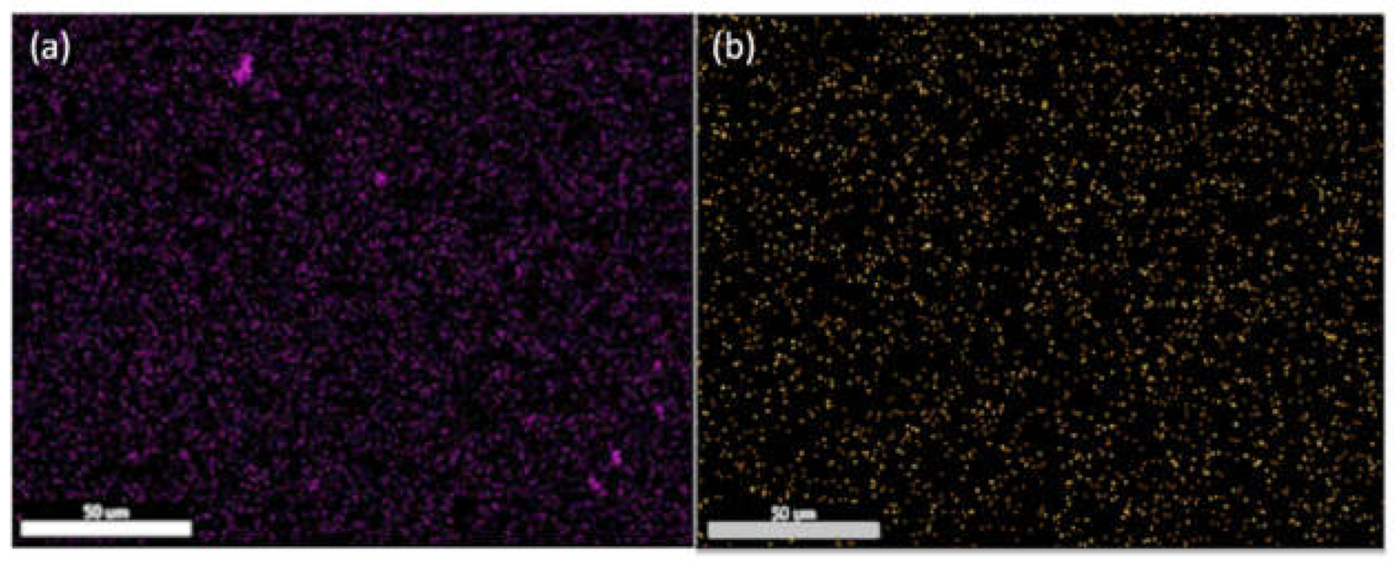
The surface morphologies of the 3D-printed PVDF/ZnS:Mn thin film are shown in Figure 2. It can be observed from the figure that the PVDF thin film was obviously composed of numerous spherulites; Mn-doped ZnS particles are distributed on or between spherulites, where the arrow points in Figure 2. The distribution-mapping maps of Mn and S in the PVDF film are shown in Figure 3. It shows that the distribution of all elements is uniform, which indicates that ZnS:Mn particles are evenly distributed in the film and make the luminescence performance of the composite film more uniform and stable.
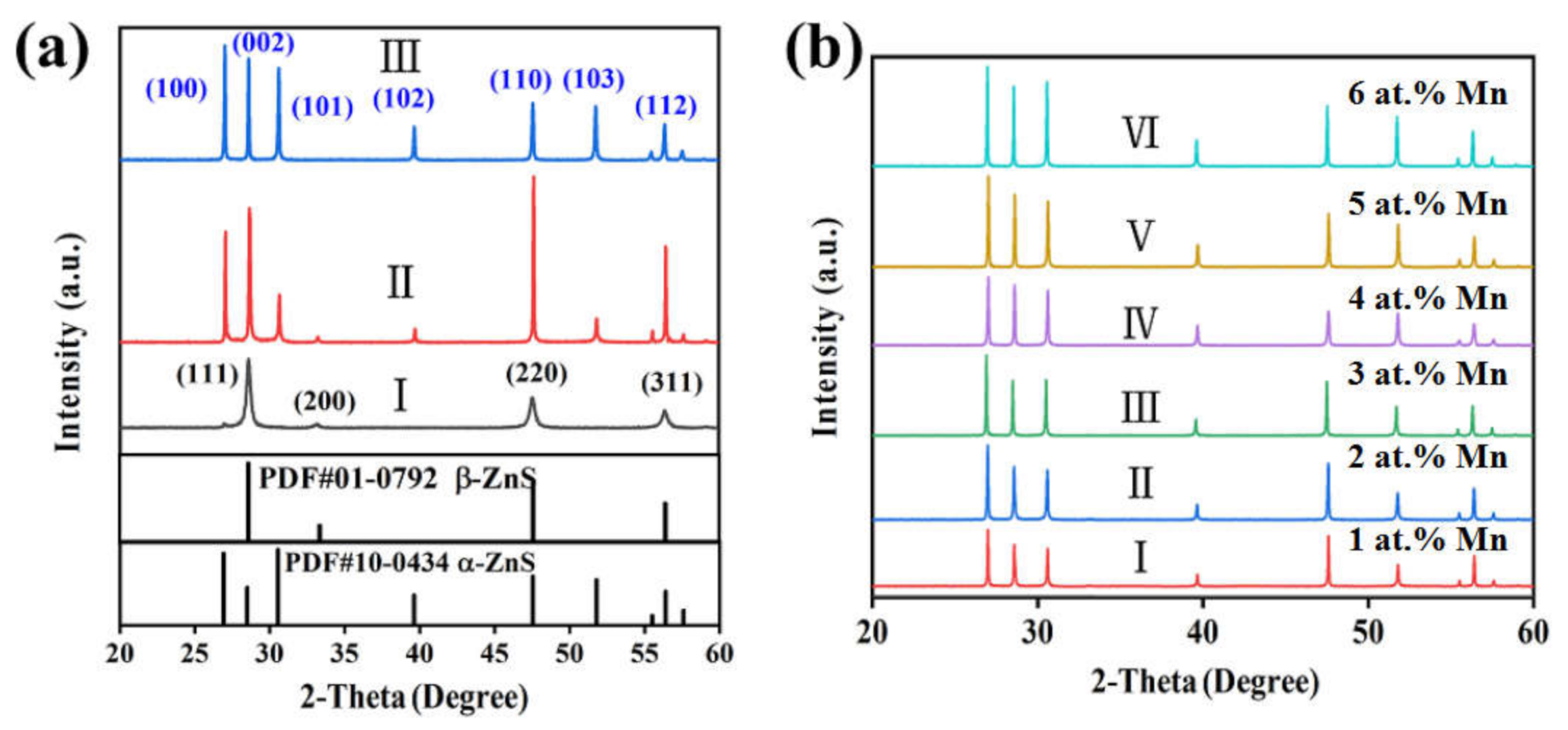
The XRD diffraction of ZnS particles is shown in Figure 4a. The curve indicates that the characteristic peaks at 2θ = 28.59, 33.35, 47.57, and 56.40 of the sample correspond to the (111), (200), (220), and (311) planes of β-ZnS, respectively. In addition, the characteristic peaks in the XRD pattern of the sintered samples correspond to α-ZnS, as shown in Curve II. It indicates that the cubic ZnS particles underwent phase transformation reaction and changed into the hexagonal crystal type.
The XRD pattern of Mn-doped ZnS is shown in Curve III in Figure 4a,b, which shows the XRD patterns of ZnS with different Mn2+ doping contents. As can be observed from Figure 4b, with the increasing of Mn2+ doping content, the diffraction peak of the (200) crystal plane of β-ZnS at 2θ = 33.35° disappeared, while the diffraction peak of the (102) crystal plane significantly increased. This means that the phase transition was very thorough after Mn2+ doping. This is because the MnCO3 added as a manganese doping source begins to break down into CO2 and MnO at 300 °C during the sintering process. The decomposed CO2 flows out with N2. MnO can melt into a liquid phase above 535 °C, which will play a role in liquid-phase sintering during the recrystallisation of β-ZnS into α-ZnS. Thus, the migration rate of material diffusion is increased, and the nucleation and growth processes of the crystal are accelerated.

3.2. Effect of ZnS:Mn on Phase Transformation of PVDF Composite Thin Films

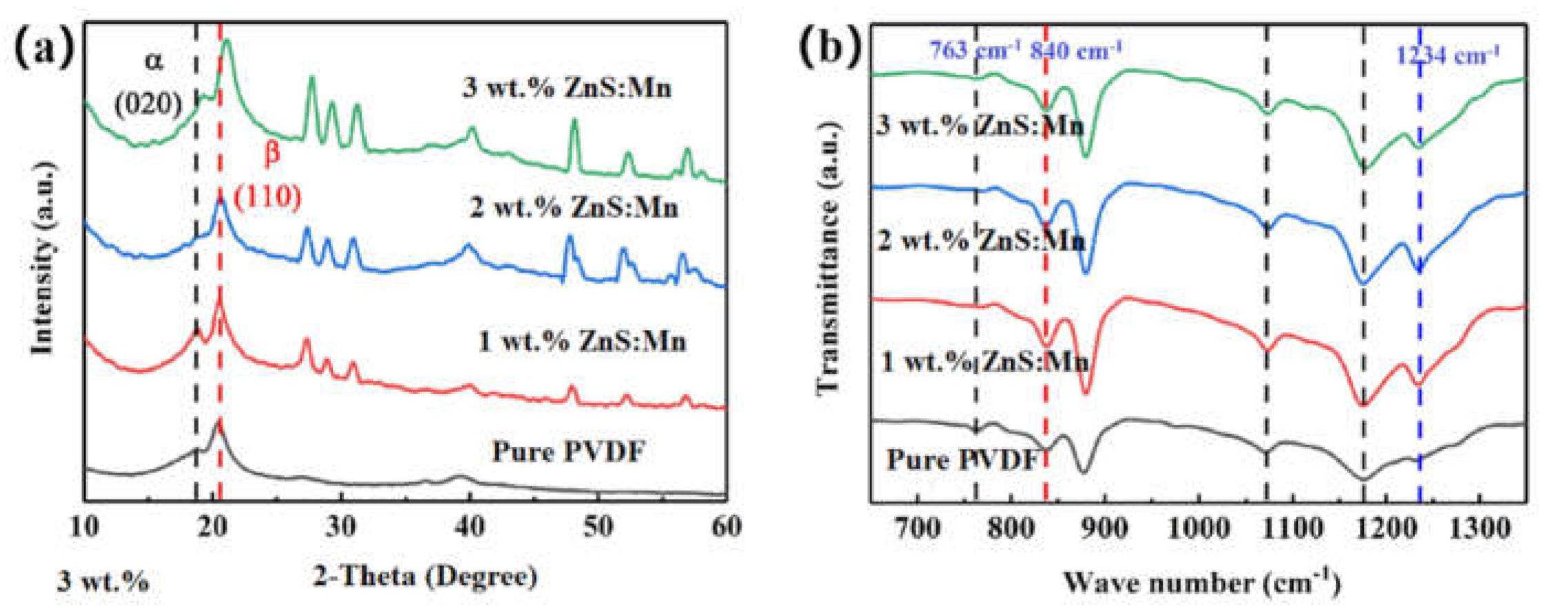
Figure 5a shows the XRD patterns of PVDF thin films containing ZnS:Mn particles with different mass percentages. The figure clearly shows the characteristic diffraction peaks of the α-phase (020) and normal β-phase (110) crystal planes of PVDF in the composite thin film. It also shows that the XRD pattern of the composite thin film with ZnS:Mn has sharp characteristic diffraction peaks on the crystal planes of hexagonal ZnS compared with that of pure PVDF film, indicating that there are ZnS:Mn particles in PVDF thin film [25,26]. In Figure 5a, the increase in ZnS:Mn particle content in the PVDF composite films results in characteristic peaks of the β-phase that are sharper than those of the normal α-phase, and the diffraction peak intensity corresponding to hexagonal ZnS:Mn also increased.
Figure 5b shows the infrared spectra of the PVDF/ZnS:Mn composite thin films with different mass fractions of ZnS:Mn particles. Different crystal forms of PVDF have unique functional groups. The corresponding crystal distribution can be determined based on the vibration frequencies of specific functional groups. As ZnS is an infrared transmittance material with high transmittance in near-infrared and mid-infrared light, the characteristic peaks in Figure 5b mainly stem from the vibration of the -CF2 group and the -CH2 functional group of PVDF.
As shown in the Figure 5b, the relative peak positions of α-phase FT-IR absorption peak were 763, 795, 853, 975, 1150, 1209 cm−1; the peak positions of β-phase absorption were 840 and 1274 cm−1 [27,28]. In addition, the change of transmittance at the infrared wave number of 1234 cm−1 in the curve represents the out-of-plane deformation and vibration of the -CF group in the γ-phase. Combined with the XRD analysis, the composite film mainly contains the β-phase, α-phase, and negligible γ-phase. Generally, the higher the β-phase content, the better the piezoelectric properties [29,30].
The relative fraction of the β-phase content (F(β)) can be obtained by the following formula [31]:
F β   =   A β K β / K α A α   +   A β
where Aα and Aβ represent the intensity of the absorption band of the FT-IR pattern at 763 cm−1 and 840 cm−1, respectively; Kα and Kβ represent the absorption coefficient at 763 cm−1 and 840 cm−1, respectively, where Kα = 6.1 × 104 cm2/mol and Kβ = 7.7 × 104 cm2/mol [32]. The F(β) values of the composite thin films with different mass fractions of ZnS:Mn are 75.2%, 79.1%, 79.6%, 81.6%, respectively. This means that the β-phase of the composite film is higher than that of the pure thin film.
3D-printed PVDF/ZnS:Mn composite thin films have a high β-phase content for some reasons. The first is because the PVDF thin films are subjected to a high voltage electric field, the temperature field from the substrate, and the tensile force of the substrate in the printing process, which jointly promote the phase transformation of PVDF [33,34]. The other reason is that the addition of ZnS:Mn particles in the printing process provides a nucleation interface and reduces the nucleation barrier, thus accelerating the non-uniform nucleation rate and promoting the formation of the crystalline phase [35].

3.3. Effect of Mn Doped on Luminescence of PVDF/ZnS:Mn Composite Film Sensors

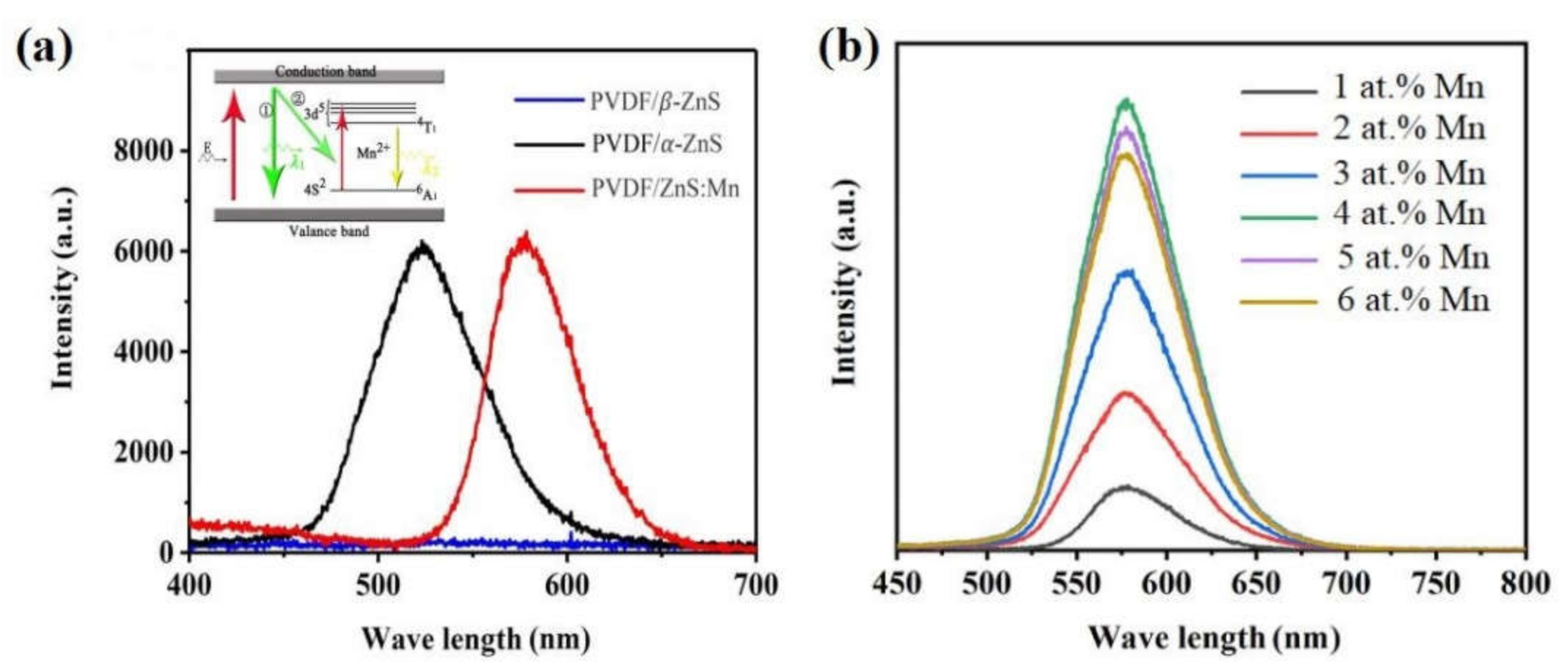
Figure 6a shows the PL spectra of the PVDF composite thin film sensors when excited by a light source with a wavelength of 320 nm. The figure shows that the PVDF thin film with β-ZnS has no luminescence properties, and with the undoped α-ZnS it demonstrated only one green emission band at approximately 530 nm. Meanwhile, for PVDF/ZnS:Mn composite film sensors, the 530 nm band was eliminated in the PL spectra and a broad yellow-orange emission band at 580 nm appeared. In addition, there is a wide minor band at 400 nm in the PL spectra. This band contains 391, 422, and 464 nm peaks, which are caused by zinc vacancies, sulfur vacancies, and sulfur bonds distributed between the ZnS grains, respectively [36,37].
Mn-doped ZnS particles distributed in PVDF film are the key to emitting yellow-orange light. Mn enters the ZnS lattice and replaces Zn2+, and its electronic structure is affected by the surrounding crystal field. When external energy is applied to the electrons in Mn, the electrons are excited to jump from the valence band to the conduction band, and the recombination of electrons and holes in the conduction band releases energy. The energy-release mechanism is shown in the upper left corner of Figure 6a. When released in the first way, the green light of wavelength λ1 = 530 nm is emitted, which is the luminescence that comes from α-ZnS. When energy is released in the second way, the transfer of energy to Mn2+ and its extranuclear electrons transitions from the ground state to the high-energy state. However, the unstable high-energy state will make the transitioned electrons go back to the stable ground state again, and the electron transition process (4T1 to 6A1) is accompanied by the release of energy in the form of light. Finally, At 580 nm, the photoluminescence intensity peaks as a typical orange-yellow emission [38].
Figure 6b shows the PL spectra of Mn-doped ZnS with different Mn content. In general, doped ions are the luminescence centres of fluorescent materials. The luminescent centre in the matrix and the luminescent intensity of the fluorescent material increases with an increase in the doping ion concentration, and its position remains unchanged. This is because Mn entering the ZnS lattice increases the number of effective luminescent centres and causes more structural defects (such as dislocation and boundary increase) in the lattice, hindering non-radiative transition and thus increasing the fluorescence intensity. However, when the doping concentration of Mn exceeds the ratio of 4 at.%, the peak luminescence intensity decreases with increased doping concentrations. At this point, the number of effective luminescent centres reached its maximum. When the doping amount continues to increase, there may be two or more Mn luminescence centres in the same cell, which increases the symmetry of the unit cell. Because of the same nature and role of Mn, mutual exclusion between ions decreases the luminescence intensity. Alternatively, due to the agglomeration of Mn, the energy absorbed by luminescent particles is transferred between Mn and is dissipated, resulting in a concentration-quenching effect in the luminescent centre. Such a behaviour is also observed in the PL spectra of PVDF/ZnS:Cu films by Sabira et al. [21,39]

3.4. Mechano-Luminesce Properties of PVDF/ZnS:Mn Composite Thin-Film Sensors

It can be observed from the above that the luminescence is the strongest when the Mn doping content is 4 at.%, and the piezoelectric performance is the best when PVDF thin film contains 3 wt.% ZnS:Mn particles. Figure 7a shows the mechano-luminesce spectrum of the PVDF composite thin-film sensor containing 3 wt.% ZnS:Mn, in which the Mn doping amount is 4 at.%. As shown in Figure 7a, the luminous band is 580 nm, which indicates that under mechanical force, the composite film emits orange light, and the mechano-luminesce centre is Mn.
Figure 7b shows the luminous intensity of the PVDF/ZnS:Mn composite thin-film sensor at each stage when the sensor is stress-loaded and offloaded from 0 to 9 N. As shown in Figure 7b, in the load stage, the mechano-luminesce intensity curve of the sensor increases gently under the stimulation of mechanical stress, whereas in the offloading stage, the intensity decreases steeply. This is because the two stages of the stress rate are different. Moreover, with the increase or decrease in stress, the PVDF/ZnS:Mn composite thin-film sensor deforms, and its luminescence intensity increases or decreases correspondingly.
When Mn was added to the ZnS crystal, an impurity band was generated in the band gap. Because Mn doping destroys the lattice integrity and causes a charge imbalance on impurity lattice points, Mn ion is affected by the electric field generated by the surrounding lattice, and the energy level splits, resulting in an optical transition.
The electric field acting on the Mn ion originates from the α-ZnS with good piezoelectric properties in the thin film as well as from the deformation degree of the PVDF matrix film. Figure 8 shows a schematic diagram of the band gap structure of the ZnS:Mn luminescence matrix in PVDF/ZnS:Mn composite film. According to Figure 8a, the band gap width of ZnS:Mn in the conventional state is Eg1. ZnS:Mn particles with hexagonal phase structure have piezoelectric properties. When subjected to external force, a piezoelectric field will be generated, and the piezoelectric potential will bend the energy band structure, which will induce the escape of electrons in traps close to the conduction band, making the emission easy. At this time, the band gap was Eg2, as shown in Figure 8b.
The PVDF thin films prepared by the 3D printing exhibit good piezoelectric properties. Under the action of an external force, PVDF will generate an external piezoelectric field around the ZnS:Mn particles. ZnS: Mn particles with hexagonal crystal structure distributed in the film also have the piezoelectric property to form the internal piezoelectric field. The internal and external piezoelectric fields cause a greater bending degree in the valence band structure in ZnS:Mn, further reducing the electron trap depth. Thus, more electrons can transition to the conduction band and the hole compound and release energy, and then stimulate the doped Mn ions to transition luminescence. As shown in Figure 8c, the band gap widths were Eg3 < Eg2 < Eg1. A smaller band gap width indicates that more electrons can transition to the conduction band. The compound of electron–hole pairs means that under the action of the same mechanical force, the efficiency of converting mechanical energy into light energy is greater, and the mechano-luminesce intensity is correspondingly greater.
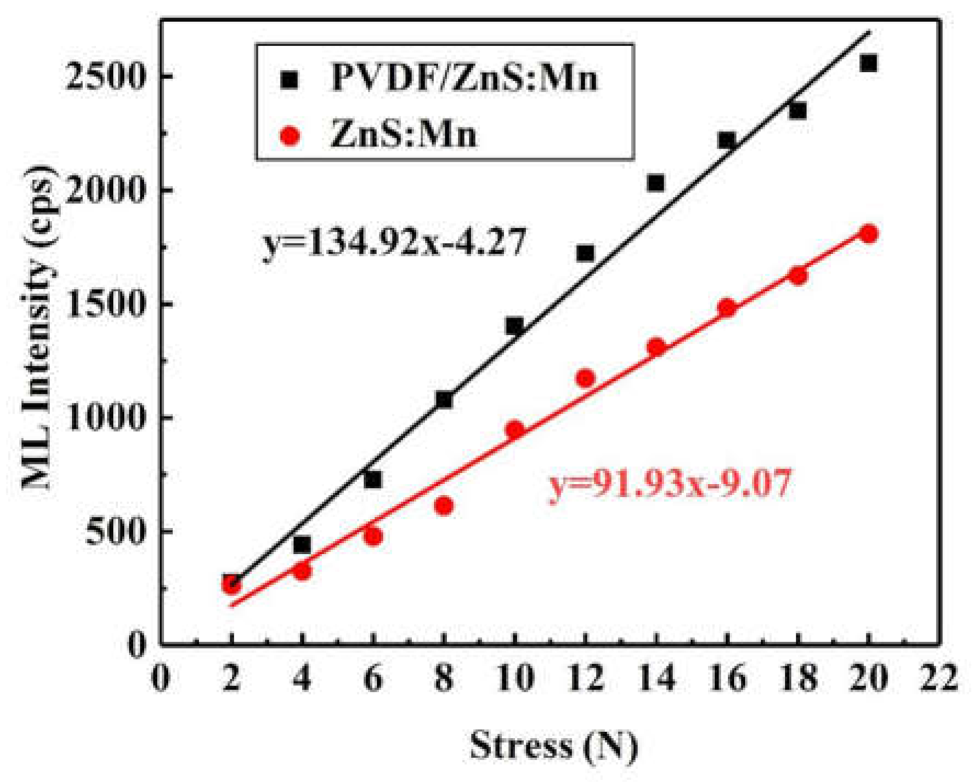
Figure 9 is the emission intensity diagram of PVDF/ZnS:Mn composite films and ZnS:Mn particles under different stresses (0–20 N). As shown in the figure, the luminescence intensity of the PVDF/ZnS:Mn composite film and ZnS:Mn particle increases gradually with an increase in the stress effect. The slope of the fitting curve of the force and luminescence intensity of the ZnS:Mn particles was 91.93, while that of the PVDF/ZnS:Mn composite film was 134.92, which indicates that under the same force, the luminescence intensity of the PVDF/ZnS:Mn composite film was stronger than that of the ZnS:Mn particles.
The luminescence intensity of the PVDF/ZnS:Mn composite film increased rapidly with the increase in the stress on the composite film. This is because not only the ZnS:Mn particles in the composite thin films produced a locally administered piezoelectric field, but also PVDF provides an external piezoelectric field. The PVDF and ZnS:Mn particles have administered this dual piezoelectric field, promoting bending and inducing the shallow trap electrons within the trap; thus, the mechano-luminesce properties of the composite membranes have a promoting effect.

4. Conclusions

In summary, PVDF/ZnS:Mn flexible composite thin films were prepared using 3D-printing techniques. Under the action of high voltage, PVDF has a β-phase transition and poling; thus, PVDF has a good piezoelectric effect. The mechano-luminescence spectra of the PVDF/ZnS:Mn composite films are consistent with the photo-luminescence spectra; they show yellow light with a wavelength of 580 nm, indicating that the luminescence centres of both photo-luminescence and mechano-luminescence are Mn ions. Mn entering the ZnS lattice increases the number of effective luminescent centres. When the doping concentration of Mn in ZnS particles is 4 at.% and the PVDF composite thin film contains 3 wt.% ZnS:Mn, the luminescence performance is the best. This can be attributed to the double piezoelectric fields. When PVDF/ZnS:Mn composite thin film sensors are subjected to external force, PVDF with high β-phase will generate an external piezoelectric field around the ZnS:Mn particles. ZnS:Mn particles with hexagonal crystal structures distributed in the film also have the piezoelectric characteristics to form the internal piezoelectric field. The double piezoelectric fields make it easy for electrons in the trap to jump to the conduction band and compound with the hole. The PVDF/ZnS:Mn composite thin film sensors demonstrate good mechano-luminescence properties.

Author Contributions

Writing—original draft, C.C.; resources, J.Z.; data curation, Y.Z.; supervision, A.W. All authors have read and agreed to the published version of the manuscript.

Funding

This research was supported by the National Natural Science Foundation of China, No. 52175464, the Jiangxi Provincial Natural Science Foundation, No. 20212BAB204047, and Jiujiang Science and Technology Project, No. S2021ZDYFG089.

Institutional Review Board Statement

Not applicable.

Informed Consent Statement

Not applicable.

Data Availability Statement

All data included in this study are available upon request by the corresponding author.

Acknowledgments

This work was supported by Jiangsu Province Key Laboratory of High-end Structural Materials.

Conflicts of Interest

The authors declare no conflict of interest.

References

  1. Mako, T.L.; Racicot, J.M.; Levine, M. Supramolecular luminescent sensors. Chem. Rev. 2019, 119, 322–477. [Google Scholar] [CrossRef] [PubMed]
  2. Urriza-Arsuaga, I.; Bedoya, M.; Orellana, G. Luminescent sensor for O2 detection in biomethane streams. Sens. Actuators B Chem. 2019, 279, 458–465. [Google Scholar] [CrossRef]
  3. Zhang, Y.; Yuan, S.; Day, G.; Wang, X.; Yang, X.; Zhou, H.C. Luminescent sensors based on metal-organic frameworks. Coord. Chem. Rev. 2018, 354, 28–45. [Google Scholar] [CrossRef]
  4. Mahata, P.; Mondal, S.K.; Singha, D.K.; Majee, P. Luminescent rare-earth-based MOFs as optical sensors. Dalt. Trans. 2017, 46, 301–328. [Google Scholar] [CrossRef] [PubMed]
  5. Lin, R.; Liu, S.; Ye, J.; Li, X.; Zhang, J. Photoluminescent metal-organic frameworks for gas sensing. Adv. Sci. 2016, 3, 1500434. [Google Scholar] [CrossRef] [PubMed]
  6. Pallotti, D.K.; Passoni, L.; Gesuele, F.; Maddalena, P.; Lettieri, S. Giant O2-Induced photoluminescence modulation in hierarchical Titanium Dioxide Nanostructures. ACS Sens. 2016, 2, 61–68. [Google Scholar] [CrossRef]
  7. Zhyrovetsky, V.M.; Popovych, D.I.; Savka, S.S.; Serednytski, A.S. Nanopowder metal oxide for photoluminescent gas sensing. Nanoscale Res. Lett. 2017, 12, 132. [Google Scholar] [CrossRef] [Green Version]
  8. Chandra, B.P.; Parganiha, S.; Chandra, V.K.; Jha, P.; Baghel, R.N. Sensing of shock-wave velocity and pressure using shock-wave induced mechanoluminescence of crystals. Sens. Actuators A Phys. 2015, 235, 196–203. [Google Scholar] [CrossRef]
  9. Gi-Woo, K.; Min-Young, C.; Ji-Sik, K. Frequency response analysis of mechanoluminescence in ZnS:Cu for non-contact torque sensors. Sens. Actuators A Phys. 2016, 240, 23. [Google Scholar] [CrossRef]
  10. Ashwini, K.; Pandurangappa, C. Solvothermal synthesis, characterization and photoluminescence studies of ZnS:Eu nanocrystals. Opt. Mater. 2014, 37, 537–542. [Google Scholar] [CrossRef]
  11. Díaz-Reyes, J.; Castillo-Ojeda, R.S.; Sánchez-Espíndola, R.; Galván-Arellano, M.; Zaca-Morán, O. Structural and optical characterization of wurtzite type ZnS. Curr. Appl. Phys. 2015, 15, 103–109. [Google Scholar] [CrossRef]
  12. Rahchamani, S.Z.; Dizaji, H.R.G.; Ehsani, M.H. Fabrication of ZnS Zigzag Sculptured Nanostructured thin Films. Procedia Mater. Sci. 2015, 11, 464–468. [Google Scholar] [CrossRef] [Green Version]
  13. Abiko, Y.; Nakayama, N.; Akimoto, K.; Yao, T. Difference in luminescence properties between Sm doped ZnS and Eu doped ZnS. Phys. Status Solidi Basic Res. 2002, 229, 339–342. [Google Scholar] [CrossRef]
  14. Ogura, T.; Mikami, A.; Tanaka, K.; Taniguchi, K.; Yoshida, M.; Nakajima, S. High-brightness green-emitting electroluminescent devices with ZnS:Tb,F active layers. Appl. Phys. Lett. 1986, 48, 1570–1571. [Google Scholar] [CrossRef]
  15. Sajan, P.; Vinod, R.; Bushiri, M.J. High luminescent yield from Mn doped ZnS at yellow-orange region and 367 nm. J. Lumin. 2015, 158, 110–115. [Google Scholar] [CrossRef]
  16. Tan, P.M.; Ngoc, T.; Nguyen, V.D.; Hien, N.T.; Hoa, V.X.; Truong, N.X.; Oanh, V.T.K.; Tam, N.D.; Ca, N.X.; Bharti, S.; et al. Study of optical properties and energy transfer mechanism of Tb3+, Sm3+ singly doped and co-doped ZnS quantum dots. Opt. Mater. 2021, 114, 1. [Google Scholar] [CrossRef]
  17. Yang, P.; Lü, M.; Xü, D.; Yuan, D.; Chang, J.; Zhou, G.; Pan, M. Strong green luminescence of Ni2+-doped ZnS nanocrystals. Appl. Phys. A Mater. Sci. Process. 2002, 74, 257–260. [Google Scholar] [CrossRef]
  18. Li, H.; Zhang, Y.; Dai, H.; Tong, W.; Zhou, Y.; Zhao, J.; An, Q. A self-powered porous ZnS/PVDF-HFP mechanoluminescent composite film that converts human movement into eye-readable light. Nanoscale 2018, 10, 5489–5495. [Google Scholar] [CrossRef]
  19. Yang, Y.J.; Aziz, S.; Mehdi, S.M.; Sajid, M.; Jagadeesan, S.; Choi, K.H. Highly Sensitive Flexible Human Motion Sensor Based on ZnSnO3/PVDF Composite. J. Electron. Mater. 2017, 46, 4172–4179. [Google Scholar] [CrossRef]
  20. Jeong, S.M.; Song, S.; Lee, S.K.; Choi, B. Mechanically driven light-generator with high durability. Appl. Phys. Lett. 2013, 102, 51110. [Google Scholar] [CrossRef]
  21. Sabira, K.; Saheeda, P.; Anila, E.I.; Jayalekshmi, S. Highly luminescent and free-standing, PVDF/doped ZnS nanocomposite films for flexible device applications. J. Lumin. 2017, 188, 490–496. [Google Scholar] [CrossRef]
  22. Sabira, K.; Saheeda, P.; Jayalekshmi, S. Blue green fluorescence from freestanding films of PVDF/ZnS:Cu Nanocomposites. Mater. Today Proc. 2017, 4, 4380–4388. [Google Scholar] [CrossRef]
  23. Koppelhuber, A.; Bimber, O. Towards a transparent, flexible, scalable and disposable image sensor using thin-film luminescent concentrators. Opt. Express 2013, 21, 4796–4810. [Google Scholar] [CrossRef] [PubMed]
  24. Wang, F.; Wang, F.; Wang, X.; Wang, S.; Jiang, J.; Liu, Q.; Hao, X.; Han, L.; Wang, J.; Pan, C.; et al. Mechanoluminescence enhancement of ZnS:Cu,Mn with piezotronic effect induced trap-depth reduction originated from PVDF ferroelectric film. Nano Energy 2019, 63, 103861. [Google Scholar] [CrossRef]
  25. Berlier, G.; Meneau, F.; Sankar, G.; Catlow, C.R.A.; Thomas, J.M.; Spliethoff, B.; Schüth, F.; Coluccia, S. Synthesis and characterisation of small ZnS particles. Res. Chem. Intermed. 2006, 32, 683–693. [Google Scholar] [CrossRef]
  26. Li, H.; Feng, S.; Liu, Y.; Shih, K. Binding of mercury species and typical flue gas components on ZnS(110). Energy Fuels 2017, 31, 5355–5362. [Google Scholar] [CrossRef]
  27. Kobayashi, M.; Tashiro, K.; Tadokoro, H. Molecular vibrations of three crystal forms of poly(vinylidene fluoride). Cheminform 1975, 43, 3053–3059. [Google Scholar] [CrossRef]
  28. Chen, C.; Cai, F.; Zhu, Y.; Liao, L.; Qian, J.; Yuan, F.; Zhang, N. 3D printing of electroactive PVDF thin films with high β-phase content. Smart Mater. Struct. 2019, 28, 65017. [Google Scholar] [CrossRef]
  29. Wang, A.; Chen, C.; Qian, J.; Yang, F.; Wang, L.; Zhang, M. Enhanced Electrical Properties of PVDF Thin Film by Addition of NaCl by Near-Electric-Field 3D Printing. J. Electron. Mater. 2021, 50, 4781–4786. [Google Scholar] [CrossRef]
  30. Gregorio, R. EM Ueno Effect of crystalline phase, orientation and temperature on the dielectric properties of poly (vinylidene fluoride) (PVDF). J. Mater. Sci. 1999, 34, 4489–4500. [Google Scholar] [CrossRef]
  31. Salimi, A.; Yousefi, A.A. Analysis Method: FTIR studies of β-phase crystal formation in stretched PVDF films. Polym. Test. 2003, 22, 699–704. [Google Scholar] [CrossRef]
  32. Esterly, D.M.; Love, B.J. Phase transformation to poly(vinylidene fluoride) by milling. J. Polym. Sci. Part. B Polym. Phys. 2004, 42, 91–97. [Google Scholar] [CrossRef]
  33. Wang, A.; Shao, M.; Yang, F.; Shao, C.; Chen, C. Preparation and properties of antibacterial PVDF composite thin films. Eur. Polym. J. 2021, 160, 110803. [Google Scholar] [CrossRef]
  34. Liao, L.; Chen, C.; Qian, J.; Zhang, Y.; Zhang, R.; Zhu, J. Direct writing of PVDF piezoelectric film based on near electric field added by [Emim]BF4. Mater. Res. Express 2020, 7, 16437. [Google Scholar] [CrossRef]
  35. Wang, A.; Chen, C.; Liao, L.; Qian, J.; Yuan, F.G.; Zhang, N. Enhanced β-Phase in Direct Ink Writing PVDF Thin Films by Intercalation of Graphene. J. Inorg. Organomet. Polym. Mater. 2020, 30, 1497–1502. [Google Scholar] [CrossRef]
  36. Sanz, M.; LoPez-Arias, M.; Marco, J.F.; de Nalda, R.; Amoruso, S.; Ausanio, G.; Lettieri, S.; Wang, R.B.X.; Castillejo, M. Ultrafast laser ablation and deposition of wide band gap semiconductors. J. Phys. Chem. C 2011, 115, 3203–3211. [Google Scholar] [CrossRef]
  37. Lu, H.; Chu, S.; Tan, S. The characteristics of low-temperature-synthesized ZnS and ZnO nanoparticles. J. Cryst. Growth 2004, 269, 385–391. [Google Scholar] [CrossRef]
  38. Qian, X.; Chen, C. Study on the Luminescence Properties of ZnS:Mn Particles by High Temperature Solid Phase Method. J. Phys. Conf. Ser. 2022, 2168, 12023. [Google Scholar] [CrossRef]
  39. Zhang, B.H.; Wu, F.Y.; Wu, Y.M.; Zhan, X.S. Fluorescent method for the determination of sulfide anion with ZnS:Mn quantum dots. J. Fluoresc. 2010, 20, 243–250. [Google Scholar] [CrossRef]
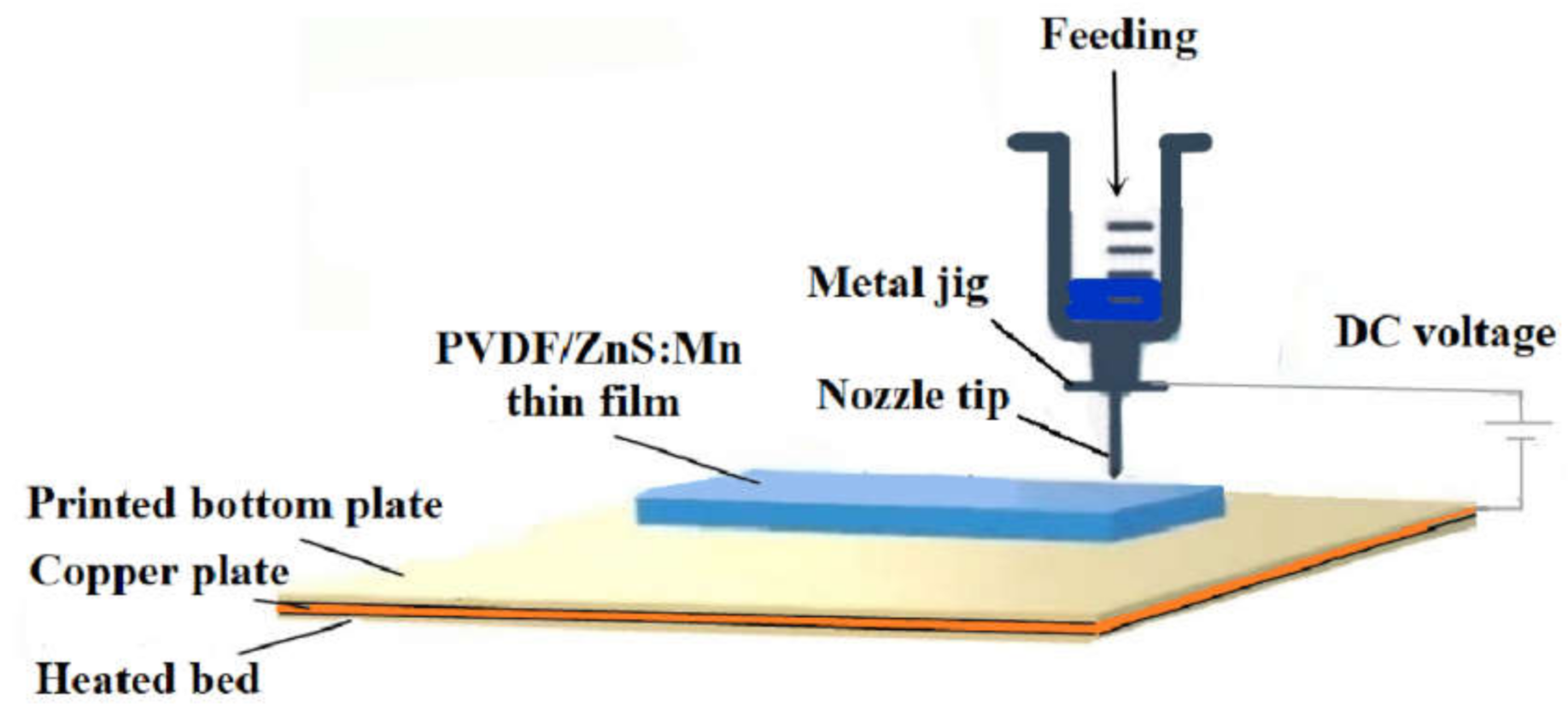
Figure 1. Schematic diagram of 3D-printed PVDF/ZnS:Mn thin film.
Coatings 12 00449 g001
Figure 2. SEM morphology of PVDF/ZnS:Mn thin films.
Coatings 12 00449 g002
Figure 3. Distribution of Mn and S element in the PVDF/ZnS:Mn thin films. (a) Mn element; (b) S element.
Coatings 12 00449 g003
Figure 4. XRD patterns of samples: (a) I, β-ZnS; II, α-ZnS; and III, α-ZnS doped with Mn; (b) I–III corresponding to doping of approximately 1–6 at.% Mn.
Coatings 12 00449 g004
Figure 5. PVDF composite thin films with different mass percentages of ZnS:Mn: (a) XRD patterns; (b) FT-IR spectra.
Coatings 12 00449 g005
Figure 6. PL spectra of PVDF composite thin-film sensors with (a) ZnS or ZnS:Mn; (b) ZnS doped with different Mn.
Coatings 12 00449 g006
Figure 7. (a) ML spectrum of PVDF/ZnS:Mn composite film sensor and (b) ML intensity of PVDF/ZnS:Mn composite film sensor varies with the load.
Coatings 12 00449 g007
Figure 8. Band gap structure of PVDF/ZnS:Mn (a) under no stress; (b) under internal piezoelectric fields; and (c) under internal and external piezoelectric fields.
Coatings 12 00449 g008
Figure 9. Relationship between the stress and ML intensity of PVDF/ZnS:Mn films and ZnS:Mn.
Coatings 12 00449 g009
Publisher’s Note: MDPI stays neutral with regard to jurisdictional claims in published maps and institutional affiliations.