Article

Effect of Texture on Total Energy Consumption of High Frequency Hydraulic Impact Piston Pair

1
Hunan Provincial Key Laboratory of Health Maintenance for Mechanical Equipment, Hunan University of Science and Technology, Xiangtan 411201, China
2
Department of Mechanical Engineering, Hunan Electrical College of Technology, Xiangtan 411201, China
*
Author to whom correspondence should be addressed.
Coatings 2022, 12(3), 340; https://doi.org/10.3390/coatings12030340
Submission received: 3 February 2022 / Revised: 4 March 2022 / Accepted: 4 March 2022 / Published: 5 March 2022

Abstract

:
Limited by the influence of the traditional clearance seal structure on the leakage and friction loss of piston pair, the energy utilization ratio of the hydraulic impactor is difficult to improve effectively. To solve this problem, a novel micro-texture clearance seal structure of impact piston cylinder was proposed, and an integrated energy consumption evaluation index considering leakage and friction loss of impact piston pair was proposed. Based on the average Reynolds equation, a comprehensive energy consumption analysis model for a textured high-frequency hydraulic impact piston pair was established, and the influence of piston texture parameters on the comprehensive energy consumption under rated working conditions was studied. The results show that the cylindrical texture clearance seal structure provided an effective way to improve the energy utilization ratio of hydraulic impactor, with energy consumption 13~15% less than the traditional structure. Variation of area rates textured made the amplitude value of integrated energy consumption of the piston pair decrease by 4~15%, and the optimum area rate was 0.2~0.4. Depth ratio of texture could also reduce the integrated energy consumption of the piston pair, but the reduction range was small.

1. Introduction

The energy utilization ratio of a hydraulic impactor is the ratio of piston impact energy to hydraulic energy. It reflects the conversion efficiency from hydraulic energy to mechanical energy of the hydraulic impactor and directly affects the drilling efficiency of the hydraulic impactor [1,2,3,4]. In the process of high frequency reciprocating, the friction loss and leakage loss of the piston pair are important parts in the total energy loss during energy transformation of the hydraulic impactor. The friction loss of the piston pair is caused by the clearance lubrication between the impact piston and the cylinder block, and the leakage loss is caused by the clearance seal. In order to improve the energy utilization rate of the hydraulic impactor, scholars at home and abroad have carried out a lot of research work on energy consumption calculation of the impact piston pair and optimization of piston structural parameters. Oh et al. [5] developed an impact performance analysis tool through the analysis of a rock drill impact module and analyzed the variation law of energy utilization rate for the hydraulic impactor relative to rock stiffness. Seo et al. [6] analyzed the performance of a hydraulic impactor through simulation considering the leakage and friction of an impact piston pair, then put forward the design method of structural parameters of an impact piston and determined the range of piston parameters. Flegneret et al. [7] tested the friction and wear of a piston during the drilling process of a hydraulic impactor under different drilling pressures and rotational speeds. In view of avoiding premature wear, the design method of the piston structure parameters for enhancing the lubrication effect was put forward, and the range of piston parameters was determined. Wang et al. [8] also established a kinematics mathematical model of an impact piston for a hydraulic impactor based on the Reynolds equation. The bearing capacity, cavity pressure, friction force, and friction energy consumption of the piston pair were studied. However, it is still limited to the conventional clearance lubrication and sealing mechanism in the design optimization of impact piston pairs mentioned above, which makes the design of declining energy consumption for an impact piston hard to realize. Increasing clearance reduces friction loss with leakage loss increase, and decreasing clearance decreases leakage loss with friction loss increase. It makes the improvement of energy utilization for a hydraulic impactor unsuccessful, and the energy utilization rate of a hydraulic impactor is much lower than that of other hydraulic actuators.
Surface texture is a micro geometric structure fabricated by special manufacturing technology on the surface with certain size, shape, and arrangement, such as micro pits and grooves. The additional hydrodynamic lubrication effect of texture can be used to improve the surface bearing capacity and reduce the surface friction [9,10,11]. It has been widely recognized as an effective means for reducing friction, decreasing wear, and increasing surface bearing capacity [12,13,14]. Pit texture is applied to the surface of the cylinder liner of an internal combustion engine to improve the lubricity of the piston pair, and the friction between the piston ring and cylinder liner is greatly reduced accordingly [15,16]. The groove texture is applied to the bearing surface to reduce the friction on the bearing surface with a more stable working parameter [17,18,19]. It has also been shown by many scholars that different morphology and parameters of texture have a significant influence on surface friction loss. Hui Zhang et al. [20] studied the friction force of surface texture parallel sliders with different morphologies and found that the hydrodynamic lubrication performance of circular textures is better with lower friction. Daniel Gropper et al. [21] analyzed the performance of bearing with variation of texture area and textured depth on a surface and found that the optimum texture depth should be slightly less than the minimum film thickness of an unreformed bearing and that an optimum texture depth and density with low friction existed. Wang et al. [22] carried out research on texture density and discovered that the friction force was reduced favorably with a texture density of 5~13%.
In order to improve the energy efficiency of a hydraulic impactor, an impact piston pair structure with a cylindrical texture is put forward. By analyzing the physical and mechanical mechanism of energy consumption of the impact piston pair, the energy consumption analysis model of the impact piston pair was established and solved numerically when combined with the Reynolds equation. The effect of texture parameters on the energy consumption of the impact piston was obtained, which provides a theoretical basis with which to design a high frequency hydraulic impactor with surface texture on the impact piston.

2. Physical Model of Textured Impact Piston Pair with High Frequency

2.1. Geometric Model of Impact Piston Pair with High Frequency

An impact piston pair with a high frequency is widely used in all kinds of impact machinery. The piston pair used in the impact mechanism of a YG45 hydraulic rock drill falls into this category, which is shown in Figure 1. It has characteristics of periodic motion with high frequency and varied velocity. The impact mechanism of the drill is composed of an impact piston, cylinder block, cylinder sleeve, front support seat, rear support seat, front chamber, rear chamber, and so on. The front chamber is usually filled with high pressure oil, and the rear chamber is alternately filled with the high pressure oil and the return oil. The impact piston moves under the pressure of the front and rear chamber.
In the impact piston pair, a clearance seal is used between the impact piston and the cylinder sleeve, and the clearance value is generally set to 55~65 μm. The piston support seat is arranged in the front and rear of the cylinder block to support and guide the impact piston. In the working process of a hydraulic impactor, high pressure oil flows from the inlet into the cylinder block and also into the front and rear chamber. Due to the difference in the bearing area of the front and rear chamber, the impact piston moves toward the right with great acceleration under the action of the pressure difference. When the load changes on both ends of the sleeve valve, the oil path will be switched. The front chamber is filled with high pressure, and the rear chamber is filled with return oil. High pressure oil in front chamber pushes the impact piston to move leftward with acceleration.

2.2. Surface Texture Model of Impact Piston

The impact piston pair of a hydraulic impactor was treated as the research object. The cylindrical texture on the shoulder surface of impact piston was set uniformly. The distribution of the cylindrical texture is shown in Figure 2.
The impact piston diameter in the diagram is 30 mm, and total length of seal is 40 mm. The oil film thickness is only 27.5 μm, and the texture is also micron. Compared with the diameter of the piston, the thickness of the oil film and the radial size of the texture can be ignored, so the influence of the radius of curvature of the oil film can be ignored, and the surface of the piston can be expanded into a plane equivalently [15]. The periodic distribution of pit texture makes the oil film thickness and oil film pressure change periodically in each texture unit area. Therefore, a single texture control unit can be selected to study, and the pressure and friction of the whole texturing area can be calculated according to the periodic arrangement characteristics. A geometric model of the texture control unit is shown in Figure 3.
A coordinate system was established on the piston surface, in which x axis is along the axis of the piston, and the y axis is set in a radial direction of the piston. Lx is the length of the control unit along the x axis, and Ly is the length of the control unit along the y axis. A is the area of the control unit. The area rate that is textured is Sp, and it can be expressed as:
S p = A L x L y

3. Analysis Model of Energy Consumption for Textured Impact Piston Pair with High Frequency

When establishing the energy consumption analysis model of the textured high-frequency impact piston valve, the following assumptions were made: the hydraulic oil is a Newtonian fluid; the cylinder-piston belongs to a rigid body, and the piston has no eccentricity in the cylinder; ignore the change in hydraulic oil temperature during piston movement.
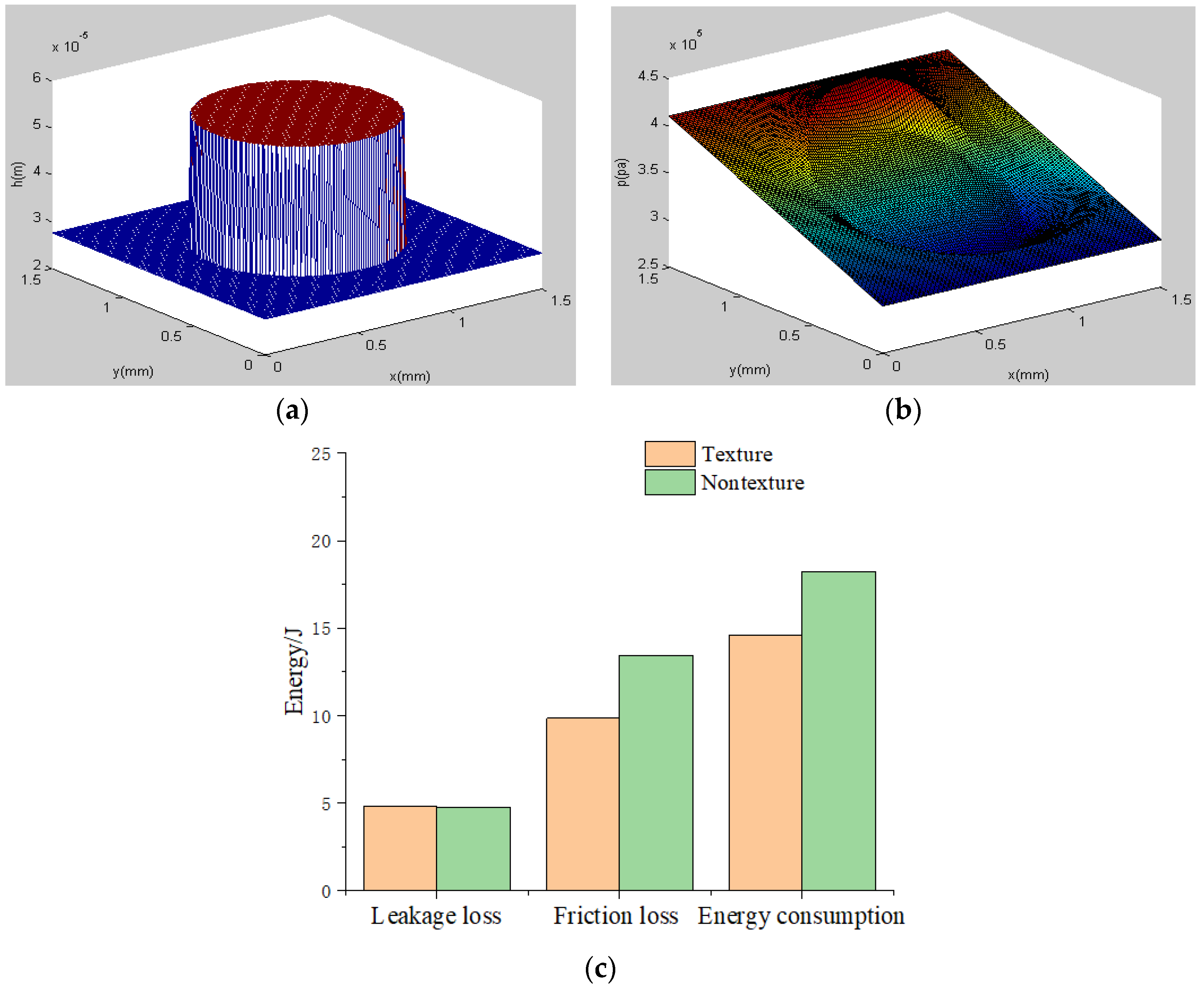
In the process of high frequency reciprocating, the friction loss and leakage loss of piston pair are important parts in total energy loss during the energy transformation of the hydraulic impactor. The friction loss of the piston pair is caused by clearance lubrication between the impact piston and the cylinder block and by the leakage loss caused by the clearance seal. In this study, energy consumption for the impact piston pair is evaluated in a cycle considering both friction loss and leakage loss. During the movement of the impact piston, the clearance between the impact piston and the cylinder block is filled with hydraulic oil to avoid direct contact with the cylinder block. The relative motion of the impact piston and cylinder block results in a dynamic oil film in the clearance. The friction force of the dynamic pressure the oil film on a solid surface is caused by the shearing force of oil. When the velocity of the impact piston increases, the friction forces increase, caused by the increase in shear force. In addition, the seal form between the impact piston and the cylinder block is the clearance seal. Hydraulic oil leakage exists at the two ends of the impact piston pair under the action of the pressure difference between the two ends of the impact piston, which will cause leakage loss.

3.1. Energy Consumption Evaluation Index of Impact Piston Pair

Considering the leakage and friction loss of the impact piston pair, the energy consumption of the impact piston pair in one cycle is calculated as follows:
W = W L + W F = 0 T P L t d t + 0 T P F t d t
where W is the energy consumption of impact piston pair in one cycle, W L = 0 T P L t d t is the leakage loss of impact piston pair in one cycle, W F = 0 T P F t d t is the friction loss of impact piston pair in one cycle, PLt is the leakage power of impact piston pair at time t, PFt is the friction power of impact piston pair at time t, T is the motion cycle of hydraulic impactor with high frequency.

3.2. Leakage Loss Calculation

Leakage loss power is determined by the pressure difference and leakage flow at both ends of the impact piston. The calculation of the loss energy of the piston pair leakage can be expressed by:
W L = 0 T P L t d t = 0 T Δ p t Q L t
where WL is the leakage loss of the impact piston pair in one cycle, PLt is the leakage power of impact piston pair at time t, Δpt is the pressure difference between two ends of impact piston pair at time t determined by working condition, QLt is the leakage flow at time t, T is the motion cycle of hydraulic impactor with high frequency.
Leakage flow varies with the change in relative velocity between the impact piston and the cylinder block. The impact piston and cylinder block are completely concentric, and the seal clearance is very small. Hence, it can be regarded as concentric ring clearance. Under the conditions of the relative motion between the piston and the cylinder, the leakage flow is the flow of the hydraulic oil in the annular clearance. It can be calculated by the flow formula of the annular clearance:
Q L t = π d h t 3 Δ p t 12 η + π d h t v t 2
where QLt is the leakage flow at time t, d is the diameter of the impact piston, ht is the leakage clearance at time t, Δpt is the pressure difference between two ends of impact piston pair at time t determined by working condition, η is the dynamic viscosity of the hydraulic oil, l is the runner length, vi is the relative velocity of the impact piston and cylinder block at time t.
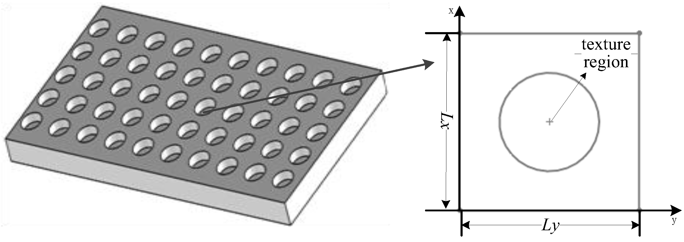
The structure of texture unit is consistent and symmetrical. The leakage clearance at time t can be approximated by the minimum film thickness of a texture element:
h t = m i n h ( x , y )
where ht is the leakage clearance at time t, h(x,y) is the film thickness distribution function of texture units.
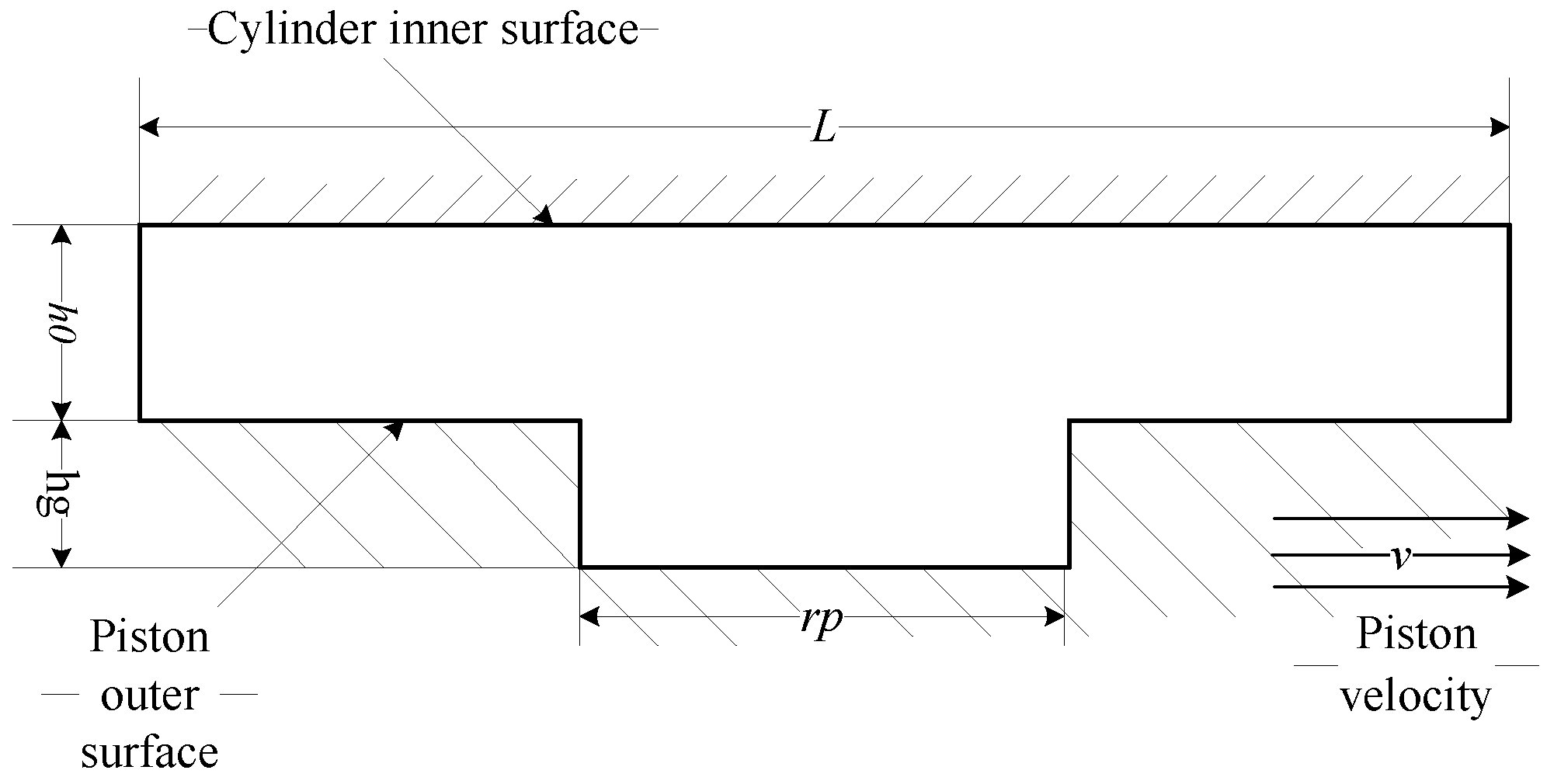
The cross section model of the flow field for a control unit with cylindrical texture is shown in Figure 4. In the figure, v is the velocity of the impact piston, h0 is the minimum initial clearance between cylinder block and impact piston, hg is the height of cylindrical texture element. Considering contact deformation under oil film pressure, the actual oil film thickness distribution function of the texture flow field can be expressed as follows:
h x , y = { h 0 + h g + v x , y               x 2 + y 2 r p 2 h 0 + v x , y                               x 2 + y 2 > r p 2
where h0 is the minimum initial clearance between the cylinder block and impact piston, hg is the height of the cylindrical texture element, v(x,y) is the contact deformation, rp is the radius of the bottom surface of the cylindrical texture element.
v ( x , y ) = 2 π E 0 L y 0 L x p ( s , z ) ( x s ) 2 + ( y z ) 2 d s d z
where v(x,y) is the contact deformation, E is the equivalent elastic modulus, p(s,z) is the oil film pressure, Lx is length of control unit along x axis, and Ly is length of control unit along y axis.

3.3. Friction Loss Calculation

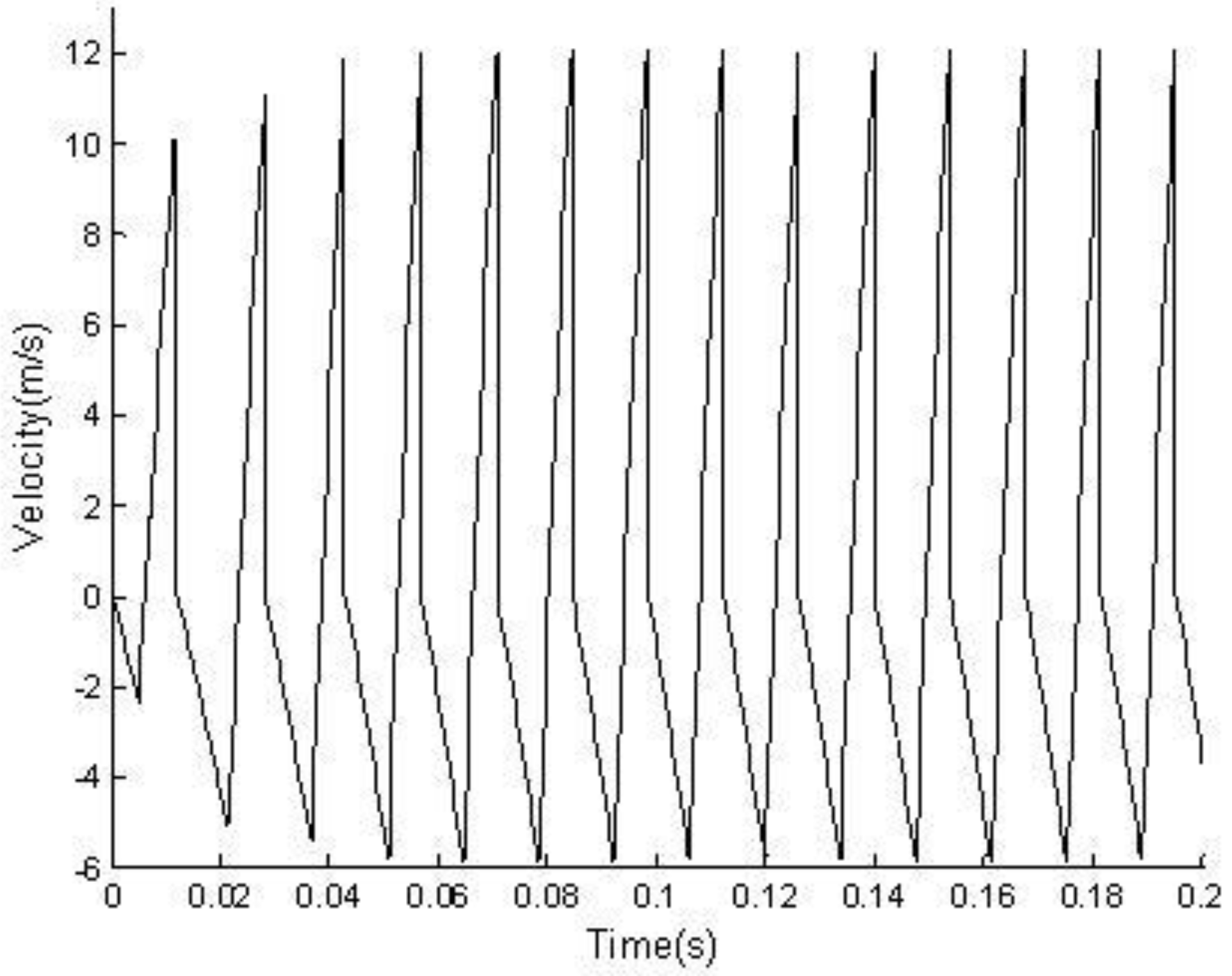
In one stroke, the change of velocity causes a change in oil film thickness, and the change in oil film thickness directly affects the friction loss of the piston pair. Therefore, the speed of the impact piston determines the loss of friction power. The equation for calculating the friction loss energy of the piston pair can be expressed by:
W F = 0 T P F t d t = 0 T F f t v t d t
where WF is the friction loss of the impact piston pair in one cycle, PFt is the friction power of the impact piston pair at time t, vi is the relative velocity of the impact piston and cylinder block at time t input according to experimental test data, Fft is the impact piston friction at time t, T is the motion cycle of the hydraulic impactor with high frequency.
Assuming that the friction produced by each texture unit is the same and that the impact piston is a rigid body, the friction force to be applied to the impact piston at time t can be expressed as:
F f t = K F f d t
where Fft is the impact piston friction applied to the impact piston at time t, Ffdt is the friction produced by single texture unit at time t, K is the total number of texture units,   K = π d L x L y , d is the diameter of the impact piston, l is the runner length, Lx is length of control unit along the x axis, Ly is length of control unit along the y axis.
The friction force of the dynamic pressure oil film on a solid surface is caused by the shearing force of oil. According to Newton’s internal friction theorem, the friction force of a single texture unit can be obtained by integrating the shear stress in the contact fluid layer along the control element.
F f d = 0 L x 0 L y ( h 2 p x + v η h ) d x d y
where Ffd is the friction force of a single texture unit of the impact piston, h is the oil film thickness, p is the oil film pressure, v is the relative velocity of the impact piston and cylinder block, η is the dynamic viscosity of hydraulic oil, L x is length of the control unit along the x axis, L y is length of the control unit along the y axis.

3.4. Oil Film Pressure Calculation for Textured Impact Piston Pair

Based on the previous assumptions and the formation mechanism of oil film pressure, the Reynolds equation of incompressible fluid under isothermal condition is written as [10]
x ( ρ h 3 p x ) + y ( ρ h 3 p y ) = 6 η x ( v ρ h )
where   ρ is the density of hydraulic oil, h is the oil film thickness, p is the oil film pressure, η is the dynamic viscosity of hydraulic oil, v is the relative velocity of the impact piston and cylinder block.
Ignoring the change in oil density and viscosity, Equation (11) can be simplified as
x ( h 3 p x ) + y ( h 3 p y ) = h x
where   = 6 v η 0 is the simplified coefficient, η 0 is the initial dynamic viscosity of hydraulic oil, v is the relative velocity of the impact piston and cylinder block.
There is a certain height gradient on the textured surface, which contains the convergence wedge and divergence wedge. Assuming that the oil film pressure is periodically distributed, the Reynolds cavitations boundary condition in fluid lubrication can be written as
p ( x , y ) 0   and   when   p ( x , y ) = 0 ,   d p d x = 0 ,
Assuming that the pressure on both sides of the impact piston changes linearly, the single texture unit has a certain pressure drop, and the oil film boundary conditions can be obtained as follows:
Δ p = p i p 0 M 1 , p ( x = 0 , y ) = p 0 + Δ p , p ( x = L x , y ) = p 0 ,
where   Δ p is the pressure difference between two ends of impact piston, p i is the supply oil pressure, p 0 is the return oil pressure, M is the number of nodes of the texture element along the x axis.
In addition, the oil film pressure distribution should satisfy the load balance equation, as shown in Equation (15):
F L 0 L y 0 L x p ( x , y ) d x d y = 0
where   F L is the equivalent load, according to the boundary conditions F L = p i + p 0 2 ( M 1 ) L x L y , p i is the supply oil pressure, p 0 is the return oil pressure, M is the number of nodes of the texture element along the x axis, L x is length of control unit along the x axis, L y is length of the control unit along the y axis.
The oil film pressure is solved with boundary conditions according to Equation (12). If the load balance equation is satisfied, the pressure distribution value of the texture unit can be obtained.

4. Numerical Solution of Energy Consumption Model for Textured Impact Piston Pair with High Frequency

After determining the size of the texture unit, the length of the texture unit along the x axis is divided into M nodes, and the length of the texture unit along the y axis is divided into N nodes. According to Equations (2), (3) and (8), taking the calculated step size as   Δ t , the energy consumption in a cycle can be solved numerically by the following equation:
W = i = 1 i = I + 1 Δ p i Q i Δ t + i = 1 i = I + 1 F f i v i Δ t
where W is the energy consumption of the impact piston pair in one cycle, I is the number of periods in a cycle I = T/Δt, T is the motion cycle of hydraulic impactor with high frequency, Δ t is the calculated step size, Δ p i is the pressure difference between two ends of impact piston at time i × Δ t , Q i is the leakage flow of hydraulic oil at time i × Δ t , F f i is the impact piston friction applied to the impact piston at time i × Δ t , v i is the velocity of the impact piston at time i × Δ t .
Combining Equations (9) and (10), the friction force can be solved by using the composite trapezoid formula, which is shown as:
F f t = K L x L y 4 ( M 1 ) ( N 1 ) j = 1 N i = 1 M [ ( h i , j 2 × p i + 1 , j p i , j Δ x + η v i h i , j ) × R i , j ]
where F f t is the impact piston friction applied to the impact piston at time t , K is the total number of texture units, d is the diameter of the impact piston,   is the runner length, L x is length of control unit along the x axis, L y is length of control unit along the y axis, M is the number of nodes of the texture element along the x axis, N is the number of nodes of the texture element along the y axis, h i , j is the thickness of oil film at the intersection of x direction node i and y direction node j , p i , j is the pressure at the junction of x direction node i and y direction node j , Δ x is the mesh length along the x axis, R i , j is the coefficient matrix, which is written as:
R i , j = [ 1 2 2 1 2 4 4 2 2 4 4 2 1 2 2 1 ] M × N
The contact deformation can be solved simply by the step function approximation method, that is:
v i j = 2 π E l = 1 N k = 1 M C k l i j p k l
where v i j is the elastic deformation at the node ( x i = i Δ x ,   y j = j Δ y ), C k l i j is the deformation produced by the unit force of the node (   x k = k Δ x ,   y l = l Δ y ) at the node ( x i = i Δ x ,   y j = j Δ y ).
C k l i j = ( | i k | + 0.5 ) ( | j l | + 0.5 )                                × { ( | i k | + 0.5 ) l n f [ ( | j l | + 0.5 ) Δ y , ( | i k | + 0.5 ) Δ x ] f [ ( | j l | 0.5 ) Δ y , ( | i k | + 0.5 ) Δ x ] Δ x                                + ( | i k | 0.5 ) l n f [ ( | j l | 0.5 ) Δ y , ( | i k | 0.5 ) Δ x ] f [ ( | j l | + 0.5 ) Δ y , ( | i k | 0.5 ) Δ x ] Δ x                                + ( | j l | + 0.5 ) l n f [ ( | i k | + 0.5 ) Δ x , ( | j l | + 0.5 ) Δ y ] f [ ( | i k | 0.5 ) Δ x , ( | j l | + 0.5 ) Δ y ] Δ y                                + ( | j l | 0.5 ) l n f [ ( | i k | 0.5 ) Δ x , ( | j l | 0.5 ) Δ y ] f [ ( | i k | + 0.5 ) Δ x , ( | j l | 0.5 ) Δ y ] Δ y }
where f ( x , y ) = x = x 2 + y 2 , Δ x = L x / ( M 1 ) is the mesh length along the x axis, Δ y = L y / ( N 1 ) is the mesh length along the y axis.
Using the difference solution method to deal with the Equation (12), the iterative formula for calculating the pressure can be obtained:
  p i , j k + 1 = A p i + 1 , j k + B p i 1 , j k + C p i , j + 1 k + D p i , j 1 k + E
where band mark k is uncorrected pressure, belt mark k + 1 is modified pressure, i is the node number of x direction, j is the node number of y direction, A , B , C , D , E is the calculated coefficient, which can be expressed in the following:
A = Δ y 2 h i + 1 , j 3 / [ ( Δ x 2 + Δ y 2 ) ( h i + 1 , j 3 + h i , j 3 ) ]        B = Δ y 2 h i , j 3 / [ ( Δ x 2 + Δ y 2 ) ( h i + 1 , j 3 + h i , j 3 ) ] C = Δ y 2 h i , j + 1 3 / [ ( Δ x 2 + Δ y 2 ) ( h i + 1 , j 3 + h i , j 3 ) ]        D = Δ y 2 h i , j 3 / [ ( Δ x 2 + Δ y 2 ) ( h i + 1 , j 3 + h i , j 3 ) ] E = Λ Δ x Δ y 2 ( h i + 1 , j h i , j ) / [ ( Δ x 2 + Δ y 2 ) ( h i + 1 , j 3 + h i , j 3 ) ]
where Δ x is the mesh length along the x axis, Δ y is the mesh length along the y axis, i is node number along the x axis, j is node number along the y axis, h is the oil film thickness, = 6 v η 0 is the simplified coefficient, η 0 is the initial dynamic viscosity of hydraulic oil, v is the relative velocity of the impact piston and cylinder block.
In order to ensure the convergence of the calculation, the super relaxation iteration method is used to modify the algorithm, that is:
p i , j k + 1 = ω p i , j k + 1 + ( 1 ω ) p i , j k
where p is the oil film pressure, i is node number along the x axis, j is node number along the y axis, band mark k is the uncorrected pressure, belt mark k + 1 is modified pressure, ω is the relaxation iteration factor.
The convergence judgment is carried out with relative precision, as follows:
j = 1 N i = 1 M | P i , j k + 1 P i , j k | j = 1 N i = 1 M P i , j k + 1 ε
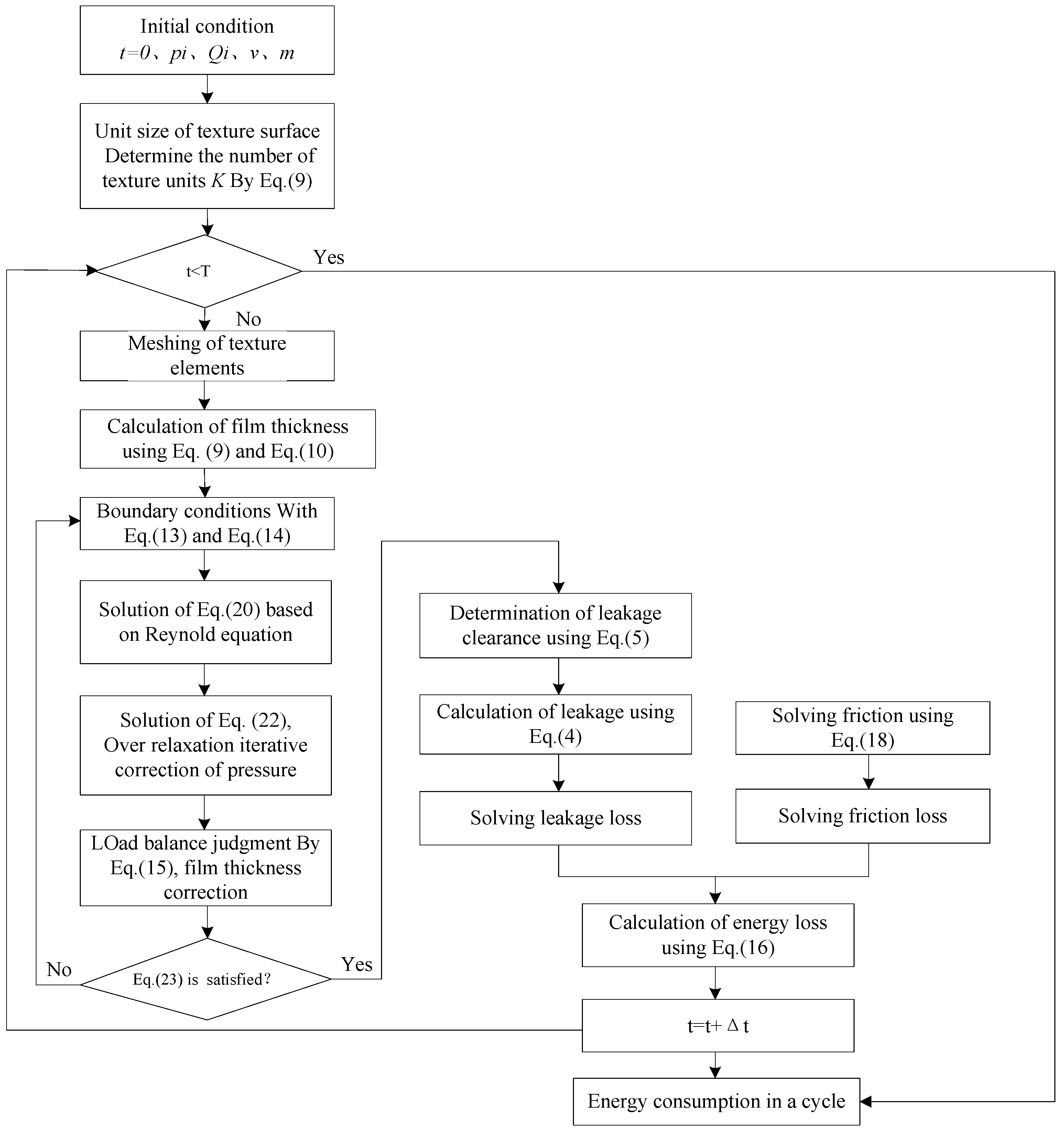
When the solution of oil film pressure is convergent, the impact piston friction applied to the impact piston can be calculated using Equation (17) by substitution of the oil film pressure solution, and the energy consumption of the impact piston pair can be calculated according to Equation (16). The specific solution process is shown in Figure 5.

5. Energy Consumption Analysis of Textured Impact Piston Pair with High Frequency

5.1. Analysis Parameters Determination of an Impact Piston Pair with High Frequency

The impact piston pair of a YG45 hydraulic impactor was taken as the analysis object. The working pressure and flow rate of the hydraulic impactor under rated working conditions were controlled as a constant by system. The maximum impact velocity was obtained by strain method measurement using the test platform built by the excavator bucket arm and the hydraulic oil source of the excavator. The experiment is shown in Figure 6. In the experiment, the supply oil pressure was set to 14 Mpa, and the supply oil flow was set to 60 m3/s. The test period of the multi-channel high-speed waveform recorder was set to 50 ms, and the data acquisition frequency was set to 1 MHZ. The amplitude–frequency characteristic curve of the stress measured after the hydraulic impactor working stably is shown in Figure 7. The maximum impact velocity of the piston was 12.9 m/s, calculated by stress wave theory according to the test stress in Figure 7. The impact frequency was 74.8 HZ, which was acquired from the amplitude–frequency characteristic curve of the stress. In other words, the motion cycle of the hydraulic impactor with high frequency was 0.013 s. According to the hydraulic–mechanical coupling model of a hydraulic impactor under rated working conditions [1], the velocity curve of the impact piston with high frequency under rated working conditions is shown in Figure 8. It shows that the piston stroke and return motion need a certain amount of time to reach a steady state, but they still show a periodic change. The reason is that the front and rear chamber pressure was not established in the initial operation. Therefore, the velocity of the impact piston can be taken as the velocity value of the impact piston in any period after stable operation. The pressure and flow parameters of the energy consumption analysis model can be set as the same values of the adjusted system. Specific parameters are as follows: the maximum motion velocity of the piston was 12.9 m/s, the oil supply pressure was 14 MPa, the oil return pressure was 0.4 MPa, and the motion cycle of hydraulic impactor was 0.013 s.

5.2. Energy Consumption Analysis of Texture Impact Piston Pair

A cylindrical texture unit was arranged on the surface of the impact piston, the length of the control unit along the x axis L x was 1.5 mm, and the length of the control unit along the y axis L y was 1.5 mm too. The area ratio textured was 30%, the dynamic viscosity of the hydraulic oil used was 0.06 P a · s , the initial oil film thickness was 27.5 μm, and the depth of cylindrical texture was 27.5 μm. The energy consumption model of the impact piston pair was calculated according to the above flowchart using MATLAB. The comparison of energy consumption between the non-textured impact piston pair and the cylindrical textured impact piston pair using the calculation results is shown in Figure 9.
The results show that the energy consumption of the cylindrical textured impact piston pair was 14.63 J in one cycle under the above parameters. Comparing with the non-textured impact piston pair, the ratio of energy consumption to total energy loss was reduced by 5.88%. The surface friction force greatly reduces with the cylindrical texture, and the reduction in surface friction greatly improves the friction performance of the surface and reduces the friction loss a lot. In addition, the leakage loss increases slightly with the cylindrical texture. However, the increased leakage loss can be ignored compared with the reduced friction loss. The cylindrical texture makes the energy consumption of the impact piston obviously reduce in general. The energy consumption of the impact piston pair was 18.24 J, and the ratio of energy consumption to total energy loss of the hydraulic impactor was 29.77%. Therefore, reducing the energy consumption of the impact piston pair can significantly improve the energy utilization rate of a hydraulic impactor.

5.3. Effects of Area Ratio Textured to Energy Consumption of Impact Piston

The control unit was square. Limited by the shape of the control unit, the maximum area ratio textured using cylindrical texture can only reach 78.5%. The thickness of oil film was set to 27.5 μm, and the depth of cylindrical texture was set to 27.5 μm. The energy consumption and energy consumption ratio to total energy loss of the impact piston pair in one cycle with different area ratio textured are shown in Table 1. The energy consumption of the non-textured impact piston pair was 18.24 J. When the cylindrical texture was used, the energy consumption was reduced, regardless of the area ratio textured, which was led by the decrease in friction loss. The energy consumption of the impact piston pair with different area ratio textured is shown in Figure 10. As can be seen from the figure, the energy consumption of the impact piston with cylindrical texture is smaller than that without texture. The energy consumption of the impact piston decreases first and then remains unchanged with the increase in area ratio textured. The energy consumption ratio of the impact piston pair to total energy loss with different area ratio textured is shown in Figure 11. It can be seen that the energy consumption ratio decreases by 1.32% to 10.98% with the area ratio textured ranging from 0.1 to 0.78. The decreasing of the energy consumption ratio shows a trend of accelerating first and then slowing down. The energy consumption ratio reaches the minimum before the area ratio textured achieves the maximum, and the energy consumption ratio can be reduced to the lowest when the area ratio textured is in the range of 0.64 to 0.70.

5.4. Effects of Depth Ratio Textured to Energy Consumption of Impact Piston

As shown in Figure 4, depth ratio textured is defined as the ratio of the height of the cylindrical texture element to the minimum initial clearance between the cylinder block and the impact piston. The thickness of oil film was set to 27.5 μm. The energy consumption and energy consumption ratio to total energy loss of the impact piston pair in one cycle with different depth ratio textured under area ratio textured ranging from 0.3 to 0.5 are shown in Table 2, Table 3 and Table 4.
When the cylindrical texture was used, the energy consumption was reduced regardless of the depth ratio textured under a certain area ratio textured. Energy consumption of the impact piston pair with different depth ratio textured under varying area ratio textured is shown in Figure 12. As can be seen from the figure, the energy consumption of the impact piston decreases first and then increases with the increase in depth ratio textured. The energy consumption ratio of the impact piston pair with different depth ratio textured under varying area ratio textured is shown in Figure 13. It can be seen that the energy consumption ratio decreased by 3.21% to 5.68%, with the depth ratio textured ranging from 0.3 to 1.3 and that the energy consumption ratio can be reduced to the lowest when the depth ratio textured is in the range of 1 to 1.1.

6. Conclusions

According to the characteristics of reciprocating periodic motion with high frequency, the energy consumption analysis model of the textured impact piston pair was established. The model was used to analyze the energy consumption of the impact piston pair of a YG-45 hydraulic impactor. The results show that:
(1) The energy consumption of the impact piston pair accounted for 29.77% in the total energy loss of the hydraulic impactor. Reducing the energy consumption of the impact piston pair was an effective way of improving the energy utilization rate of the hydraulic impactor.
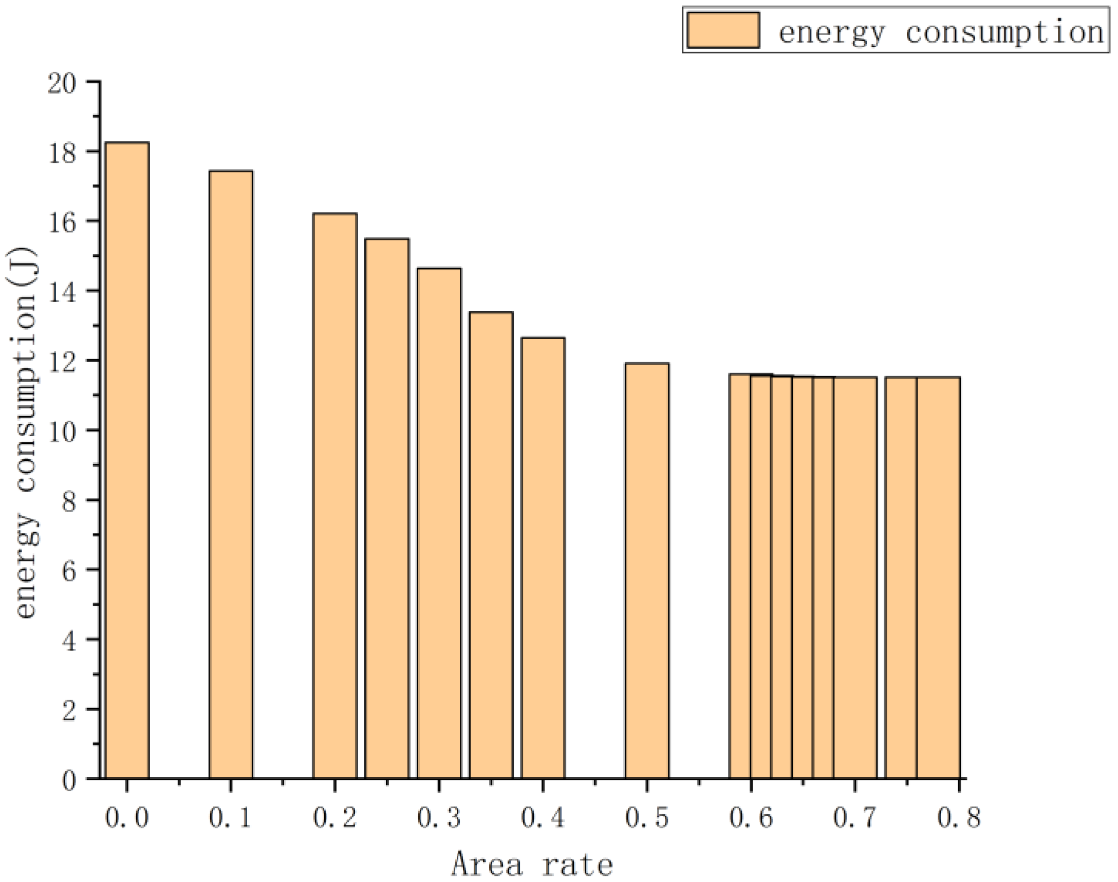
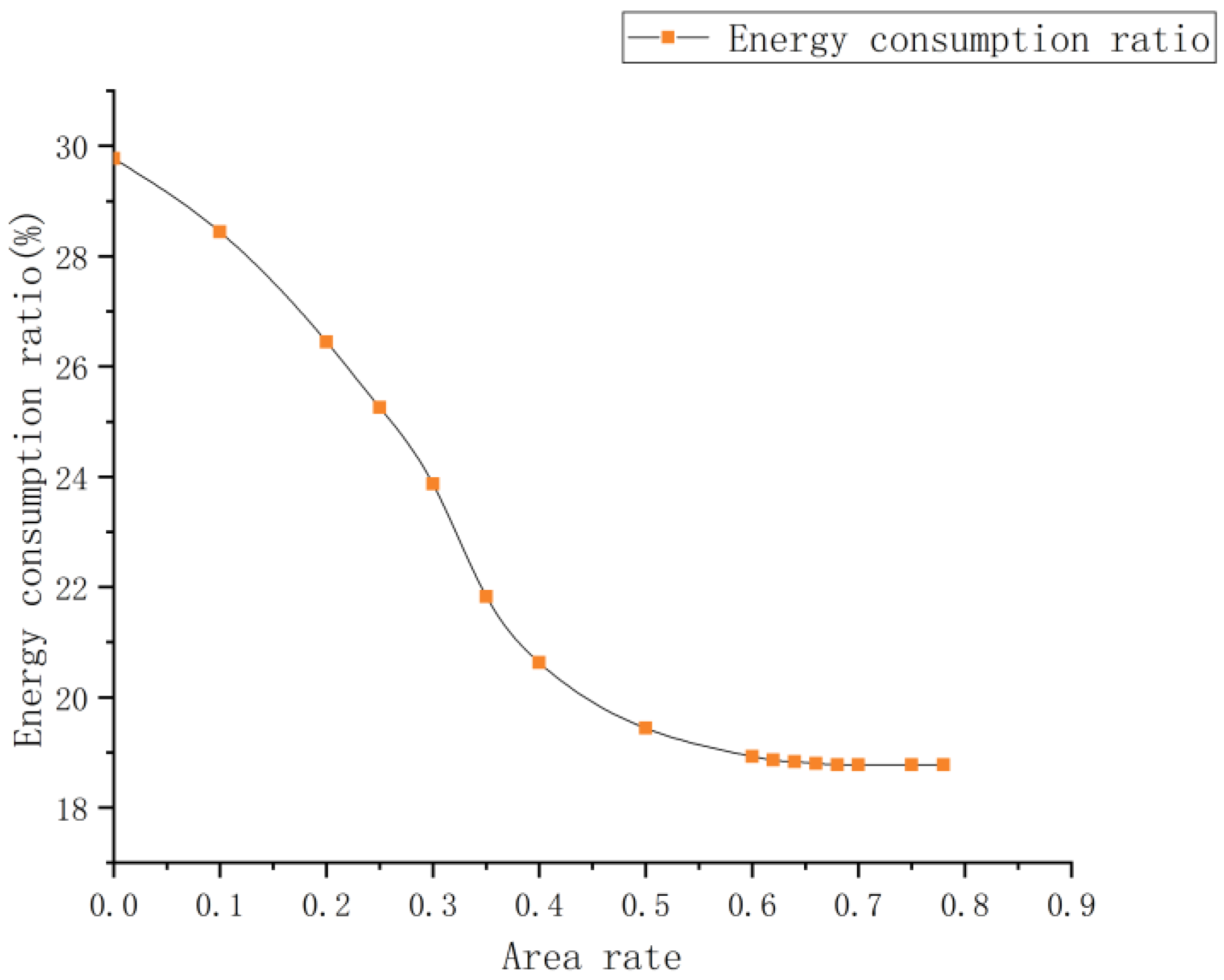
(2) The energy consumption of the impact piston pair with cylindrical texture was reduced regardless of the area ratio textured. The energy consumption ratio decreased by 1.32% to 10.98% with the area ratio textured ranging from 0.1 to 0.78, and the energy consumption ratio can be reduced to the lowest when the area ratio textured is in the range of 0.64 to 0.70.
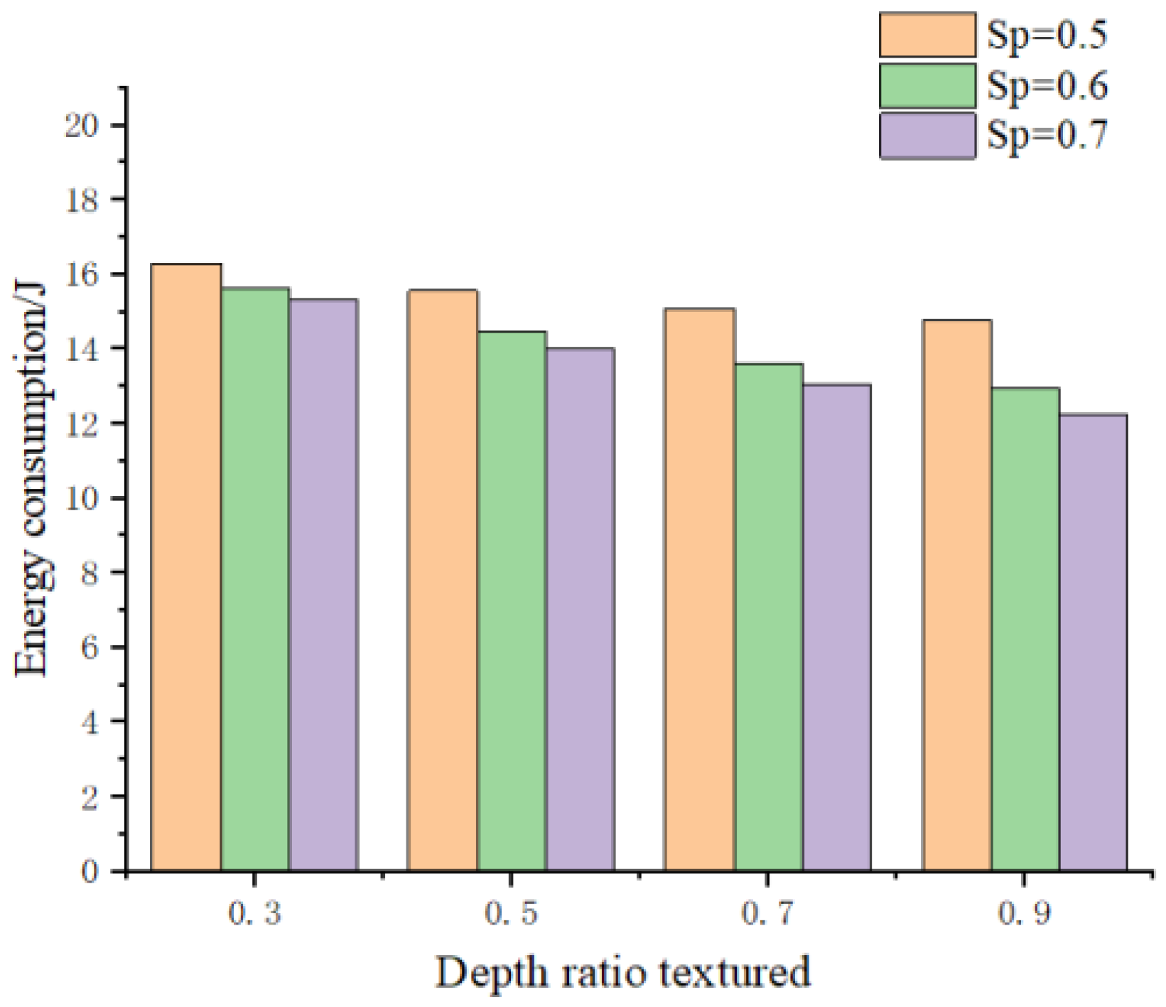
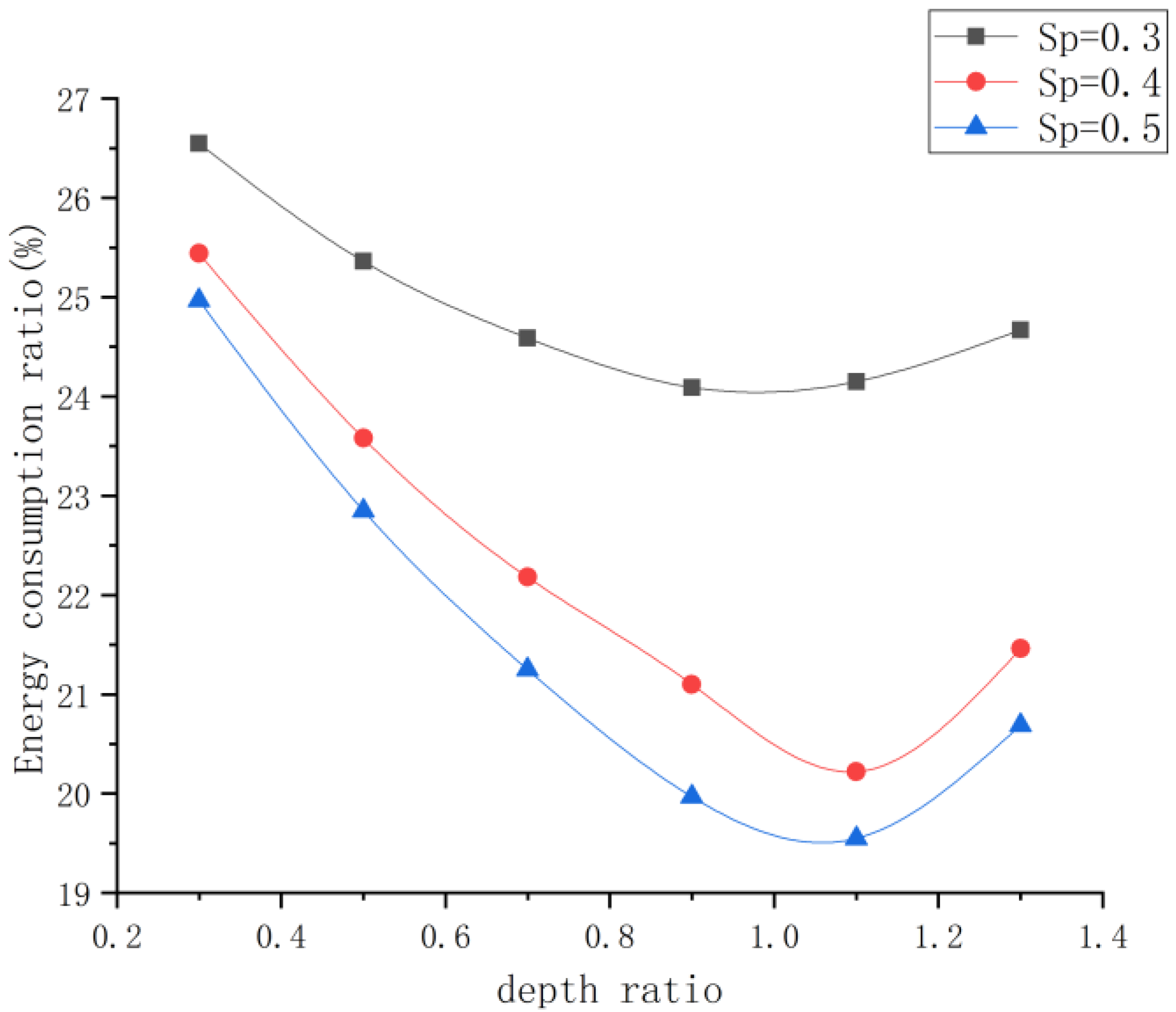
(3) The energy consumption of impact piston pair with cylindrical texture was also reduced regardless of the depth ratio textured, but the value by which it was reduced was slight. The energy consumption ratio decreased by 3.21% to 5.68% with the depth ratio textured ranging from 0.3 to 1.3, and the energy consumption ratio can be reduced to the lowest when the depth ratio textured is in the range of 1 to 1.1.0.

Author Contributions

Structure design, Y.G. and H.M.; simulation and data analysis, H.M. and S.Q.; writing—original draft preparation, S.Q.; equipment debugging and data management, H.M.; writing—review and editing, H.M., Y.G. and S.Q. All authors have read and agreed to the published version of the manuscript.

Funding

This work was funded by the National Natural Science Foundation of China under Grant 51705147 and 52075163, the Hunan Provincial Natural Science Foundation of China under Grant 2018JJ3182, and the Scientific Research Fund of Hunan Provincial Education Department 19B191.

Institutional Review Board Statement

Not applicable.

Informed Consent Statement

Not applicable.

Data Availability Statement

Not applicable.

Conflicts of Interest

The authors declare no conflict of interest.

References

  1. Hu, Q.; Yang, C.H.; Zheng, H.; Chen, M. Dynamic simulation and test research of impact performance of hydraulic rock drill with no constant-pressurized chamber. Automat. Constr. 2014, 37, 211–216. [Google Scholar] [CrossRef]
  2. Guo, Y.; Liu, D.S.; Yang, S.Y.; Li, X.J.; Chen, J.W. Hydraulic–mechanical coupling modeling by bond graph for impact system of a high frequency rock drill drifter with sleeve distributor. Automat. Constr. 2019, 63, 88–99. [Google Scholar] [CrossRef]
  3. Yang, S.Y.; Ou, Y.B.; Guo, Y.; Wu, X.M. Analysis and optimization of the working parameters of the impact mechanism of hydraulic rock drill based on a numerical simulation. Int. J. Precis. Eng. Manuf. 2017, 18, 971–977. [Google Scholar] [CrossRef]
  4. Qi, H.M.; Zhang, N.; Chen, Y.C.; Tan, B.H. A comprehensive tune of coupled roll and lateral dynamics and parameter sensitivity study for a vehicle fitted with hydraulically interconnected suspension system. Proc. Inst. Mech. Eng. Part D-J. Automob. Eng. 2021, 235, 143–161. [Google Scholar] [CrossRef]
  5. Oh, J.Y.; Lee, G.H.; Kang, H.S.; Song, C.S. Modeling and performance analysis of rock drill drifters for rock stiffness. Int. J. Precis. Eng. Manuf. 2012, 13, 2187–2193. [Google Scholar] [CrossRef]
  6. Seo, J.; Noh, D.K.; Lee, G.H.; Jang, J.S. A percussion performance analysis for rock-drill drifter through simulation modeling and experimental validation. Int. J. Precis. Eng. Manuf. 2016, 17, 163–170. [Google Scholar] [CrossRef]
  7. Flegner, P.; Kaču, J.; Durdán, M.; Laciak, M.; Stehlíková, B.; Pástor, M. Significant damages of core diamond bits in the process of rocks drilling. Eng. Fail. Anal. 2016, 59, 354–365. [Google Scholar] [CrossRef]
  8. Wang, X.; Yamaguchi, A. Characteristics of hydrostatic bearing/seal parts for water hydraulic pumps and motors. Part 1: Experiment and theory. Tribol. Int. 2002, 35, 425–433. [Google Scholar] [CrossRef]
  9. Grabon, W.; Koszela, W.; Pawlus, P.; Ochwat, S. Improving tribological behaviour of piston ring-cylinder liner frictional pair by liner surface texturing. Tribol. Int. 2013, 61, 102–108. [Google Scholar] [CrossRef]
  10. Gropper, D.; Wang, L.; Harvey, T.J. Hydrodynamic lubrication of textured surfaces: A review of modeling techniques and key findings. Tribol. Int. 2016, 94, 509–529. [Google Scholar] [CrossRef] [Green Version]
  11. Zhou, J.J.; Li, T.R.; Wang, D.Y. A novel approach of studying the fluid–structure–thermal interaction of the piston–cylinder interface of axial piston pumps. Appl. Sci. 2021, 11, 8843. [Google Scholar] [CrossRef]
  12. Wang, T.; Huang, W.F.; Liu, X.F.; Li, Y.J.; Wang, Y.M. Experimental study of two-phase mechanical face Seals with laser surface texturing. Tribol. Int. 2014, 72, 90–97. [Google Scholar] [CrossRef]
  13. Sedlaček, M.; Podgornik, B.; Ramalho, A.; Česnik, D. Influence of geometry and the sequence of surface texturing process on tribological properties. Tribol. Int. 2017, 115, 268–273. [Google Scholar] [CrossRef]
  14. Grützmacher, P.G.; Rosenkranz, A.; Rammacher, S.; Gachot, C.; Mücklicha, F. The influence of centrifugal forces on friction and wear in rotational sliding. Tribol. Int. 2017, 116, 256–263. [Google Scholar] [CrossRef]
  15. Guo, Z.W.; Yuan, C.Q.; Liu, P.; Peng, Z.X.; Yan, X.P. Study on influence of cylinder liner surface texture on lubrication performance for cylinder liner–piston ring components. Tribol. Lett. 2013, 51, 9–23. [Google Scholar] [CrossRef]
  16. Grützmacher, P.G.; Rosenkranz, A.; Szurdak, A.; Grüber, M.; Gachot, C.; Hirt, G.; Mücklicha, F. Multi-scale surface patterning-an approach to control friction and lubricant migration in lubricated systems. Ind. Lubr. Tribol. 2019, 71, 1007–1016. [Google Scholar] [CrossRef]
  17. Khatri, C.B.; Sharma, S.C. Influence of textured surface on the performance of non-recessed hybrid journal bearing operating with non-Newtonian lubricant. Tribol. Int. 2016, 95, 221–235. [Google Scholar] [CrossRef]
  18. Gachot, C.; Hsu, C.J.; Suárez, S.; Grützmacher, P.; Rosenkranz, A.; Stratmann, A.; Jacobs, G. Microstructural and chemical characterization of the tribolayer formation in highly loaded cylindrical roller thrust bearings. Lubricants 2016, 4, 19. [Google Scholar] [CrossRef] [Green Version]
  19. Rosenkranz, A.; Grützmacher, P.G.; Gachot, C.; Costa, H.L. Surface texturing in machine elements-a critical discussion for rolling and sliding contacts. Adv. Eng. Mater. 2019, 37, 1900194. [Google Scholar] [CrossRef]
  20. Zhang, Y.; Zeng, L.C.; Wu, Z.P.; Ding, X.Z.; Chen, K.S. Synergy of surface textures on a hydraulic cylinder piston. Micro. Nano. Lett. 2019, 14, 424–429. [Google Scholar] [CrossRef]
  21. Gropper, D.; Harvey, T.; Wang, L. Numerical analysis and optimization of surface textures for a tilting pad thrust bearing. Tribol. Int. 2018, 124, 134–144. [Google Scholar] [CrossRef]
  22. Wang, X.L.; Wang, J.Q.; Zhang, B.; Huang, W. Design principles for the area density of dimple patterns. Proc. Inst. Mech. Eng. Part J-J. Eng. Tribol. 2015, 229, 538–546. [Google Scholar] [CrossRef]
Figure 1. Impact mechanism of YG45 hydraulic rock drill.
Coatings 12 00340 g001
Figure 2. Cylindrical texture geometric model of impact piston surface.
Coatings 12 00340 g002
Figure 3. Geometric model of texture control unit.
Coatings 12 00340 g003
Figure 4. Cross-section model of flow field for control unit with cylindrical texture.
Coatings 12 00340 g004
Figure 5. Flow chart for solving energy consumption loss.
Coatings 12 00340 g005
Figure 6. Testing system of YG45 impactor.
Coatings 12 00340 g006
Figure 7. Amplitude-frequency characteristic curve of stress.
Coatings 12 00340 g007
Figure 8. Velocity curve of impact piston under rated working condition.
Coatings 12 00340 g008
Figure 9. Calculation results. (a) Thickness of oil slick for a unit. (b). Pressure distribution for a- unit. (c) Comparison of energy consumption.
Coatings 12 00340 g009
Figure 10. Energy consumption with different area ratio textured.
Coatings 12 00340 g010
Figure 11. Energy consumption ratio with different area ratio textured.
Coatings 12 00340 g011
Figure 12. Energy consumption with different depth ratio textured under varying area ratio textured.
Coatings 12 00340 g012
Figure 13. Energy consumption ratio with different depth ratio textured under varying area ratio textured.
Coatings 12 00340 g013
Table 1. Energy consumption and its ratio in one cycle with different area ratio textured.
Area Ratio Textured/%00.10.20.250.30.350.40.50.6
Energy consumption/J18.2417.4316.2115.4814.6313.3812.6411.9111.60
Energy consumption ratio/%29.7728.4426.4525.2623.8721.8320.6319.4418.93
Area ratio textured/%0.620.640.660.680.70.750.78--
Energy consumption/J11.5611.5411.5211.5111.5111.5111.51--
Energy consumption ratio/%18.8618.8318.8018.7818.7818.7818.78--
Table 2. Energy consumption and its ratio in one cycle with different depth ratio textured when area ratio textured is 0.3.
Depth Ratio Textured0.30.50.70.91.11.3
Energy consumption/J16.2715.5415.0714.7614.8015.12
Energy consumption ratio/%26.5525.3624.5924.0924.1524.67
Table 3. Energy consumption and its ratio in one cycle with different depth ratio textured when area ratio textured is 0.4.
Depth Ratio Textured0.30.50.70.91.11.3
Energy consumption/J15.5914.4513.5912.9312.3913.15
Energy consumption ratio/%25.4423.5822.1821.1020.2221.46
Table 4. Energy consumption and its ratio in one cycle with different depth ratio textured when area ratio textured is 0.5.
Depth Ratio Textured0.30.50.70.91.11.3
Energy consumption/J15.3014.0013.0212.2411.9812.68
Energy consumption ratio/%24.9722.8521.2519.9719.5520.69
Publisher’s Note: MDPI stays neutral with regard to jurisdictional claims in published maps and institutional affiliations.

