
HIPIMS/UBM PVD Coating Equipment Designed to Coat Universal Sized Broaches

Abstract
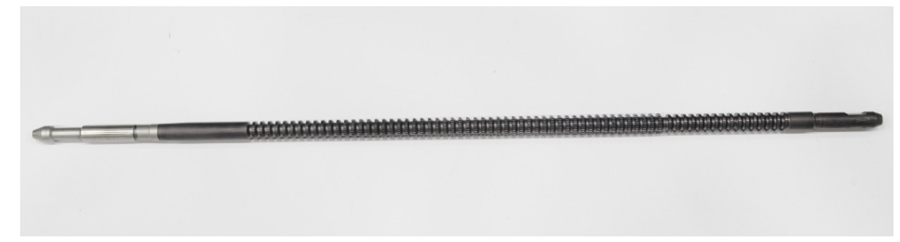
:1. Introduction
2. Materials and Methods
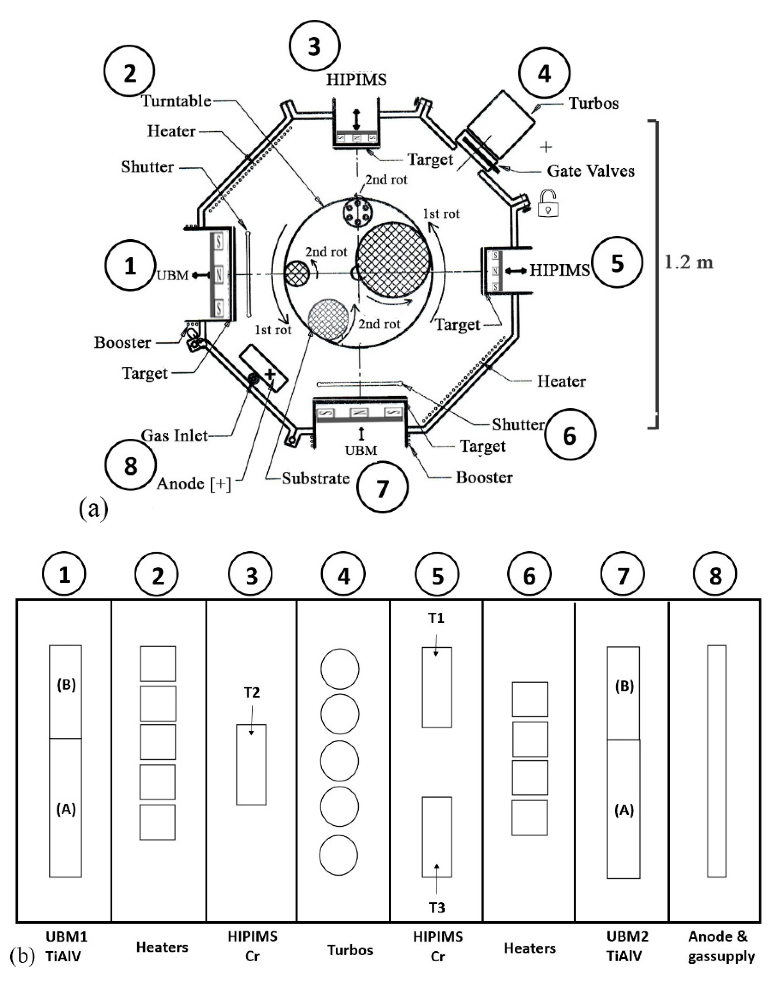
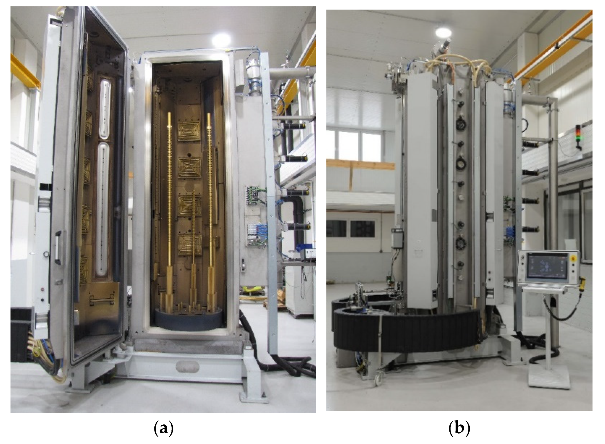
2.1. Equipment Design
2.2. Power Supplies
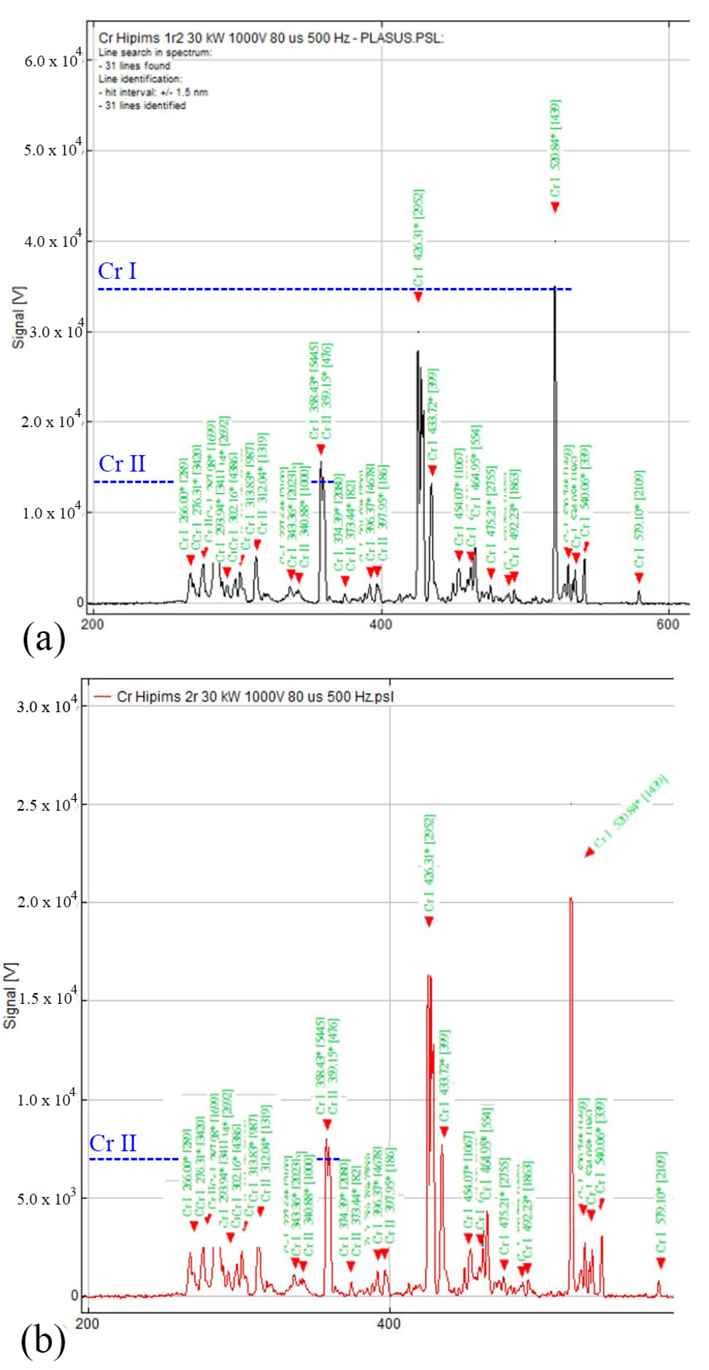
2.3. Analyses of HIPIMS Plasma
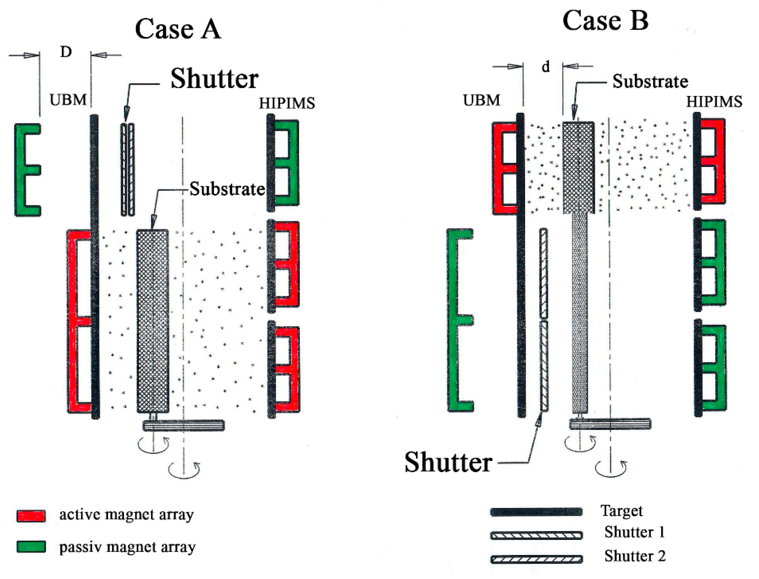
2.4. Segmentation of the UBM Process
2.5. (CASE A) Deposition
2.5.1. In Vacuo Pretreatment
2.5.2. Formation of the Ramping Socket
2.5.3. Deposition of Type 1 Coating
2.5.4. Deposition of Type 2 Coating
2.5.5. Deposition of Type 3 Coating
3. Results and Discussion
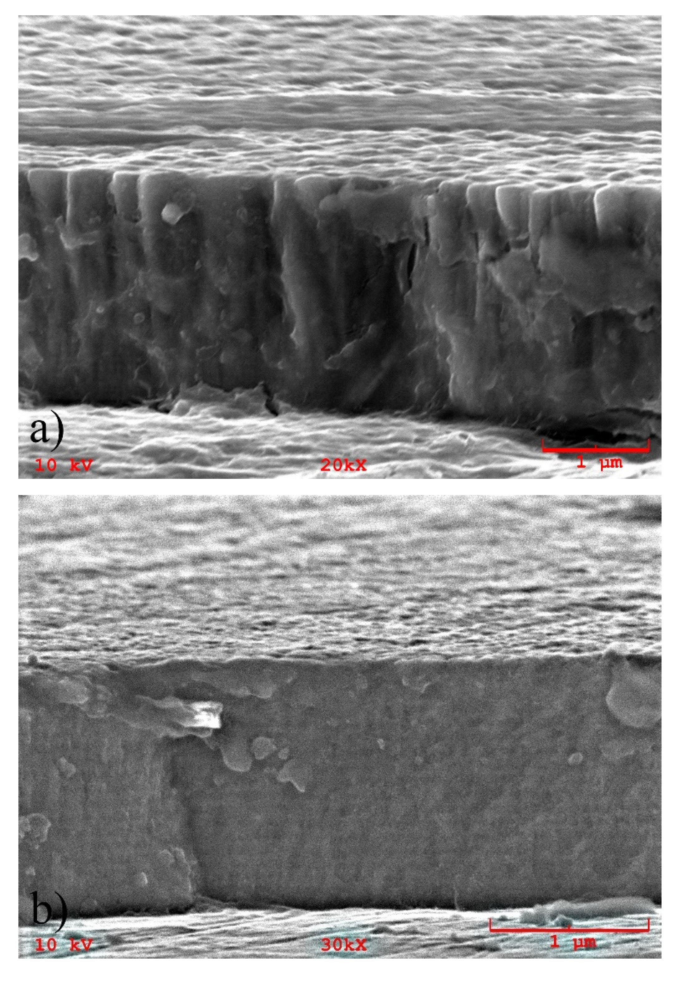
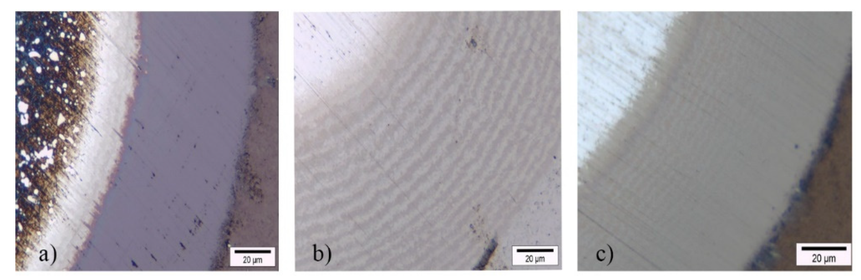
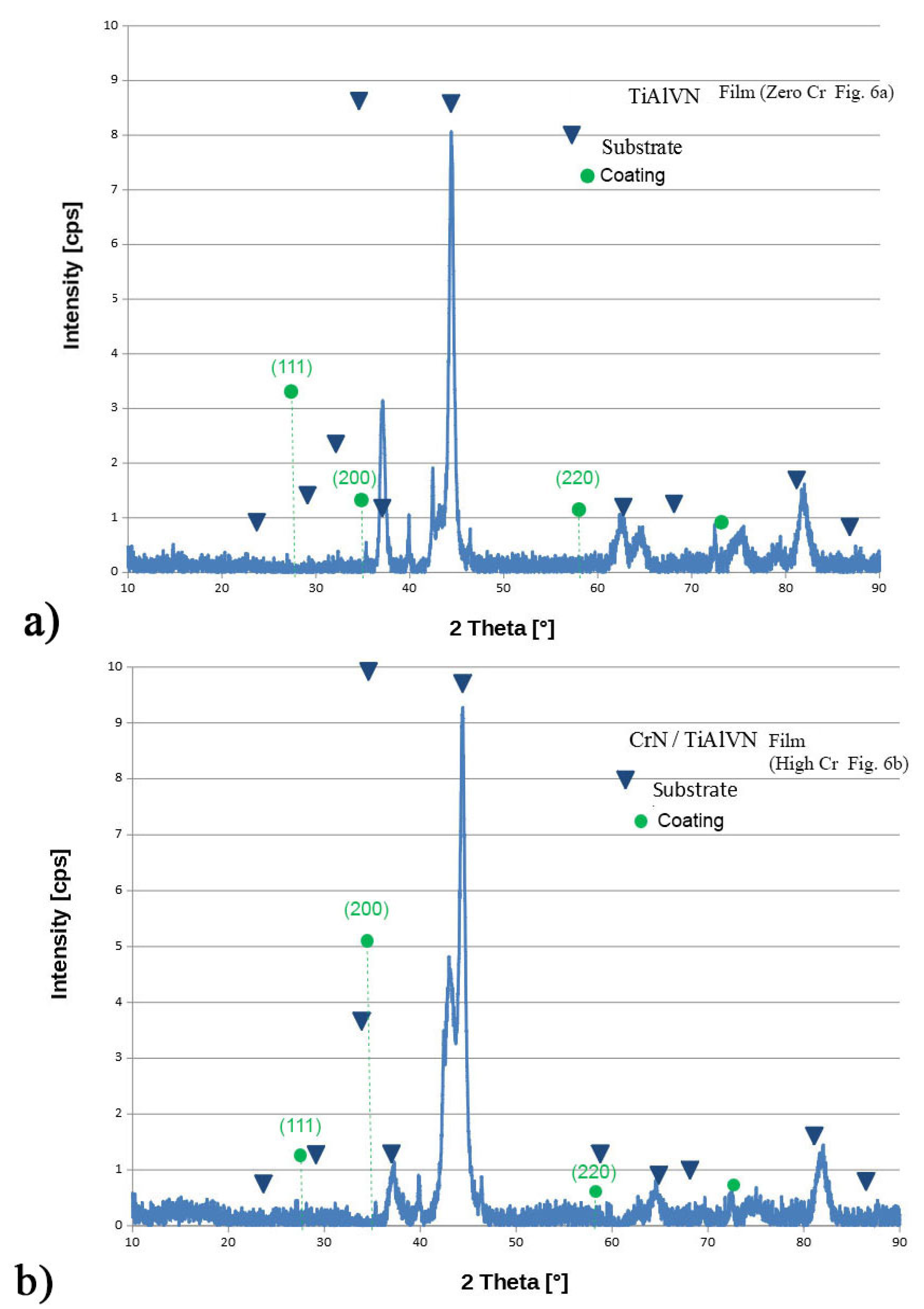
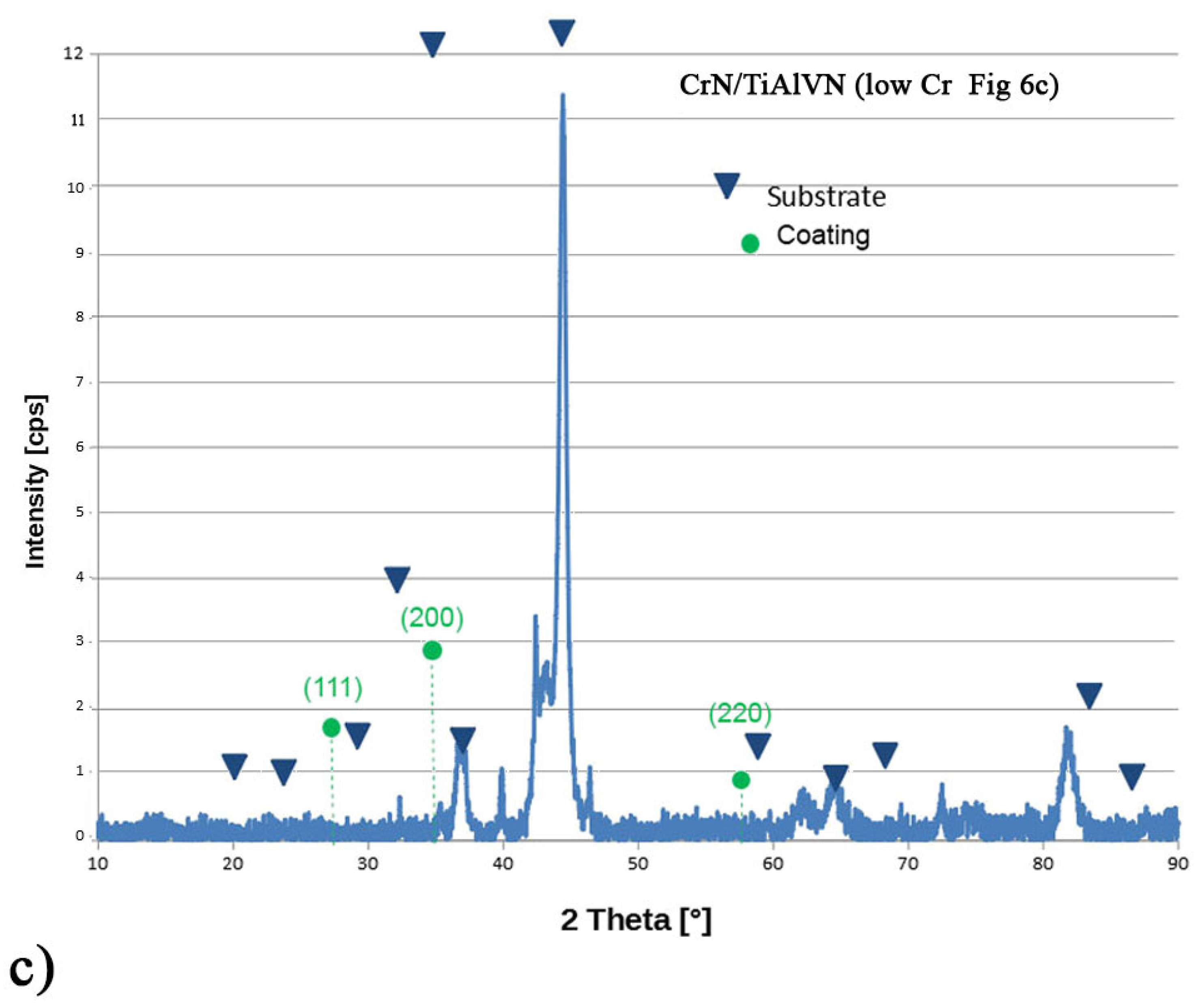
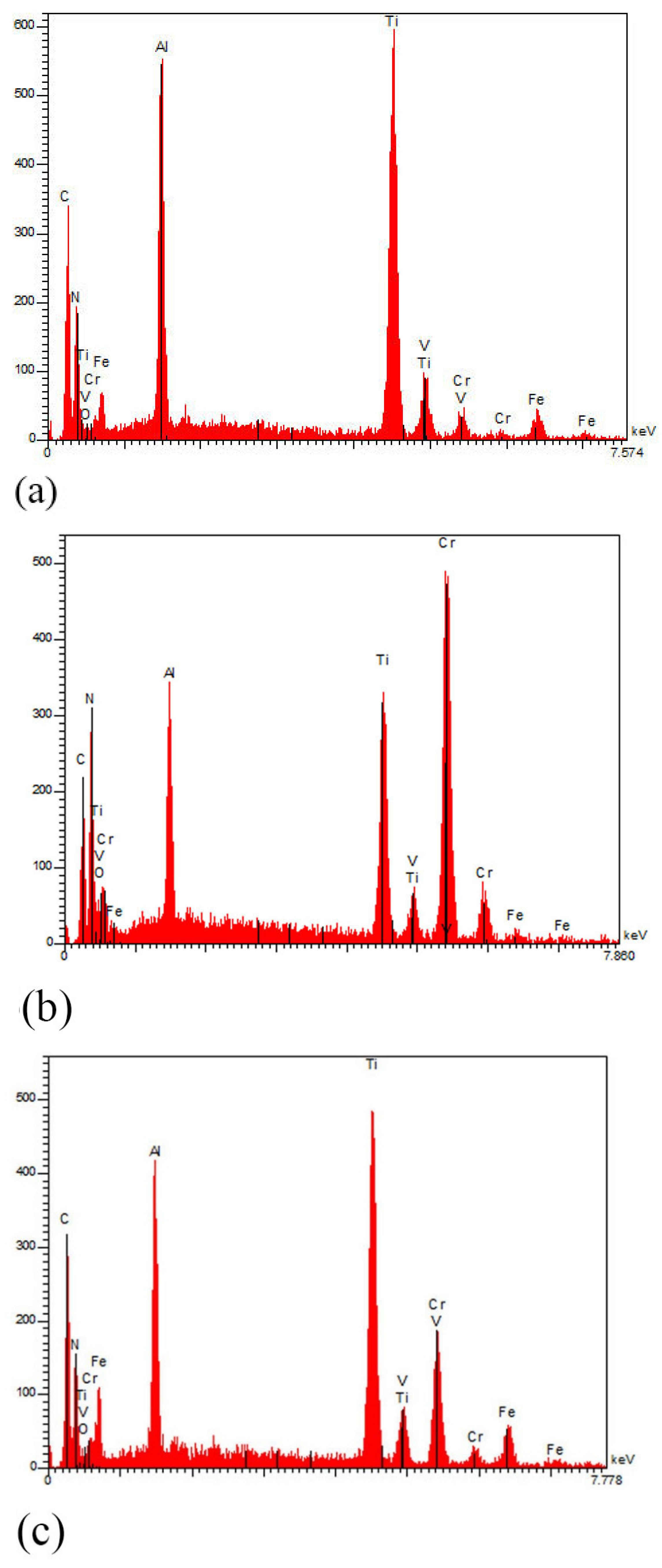
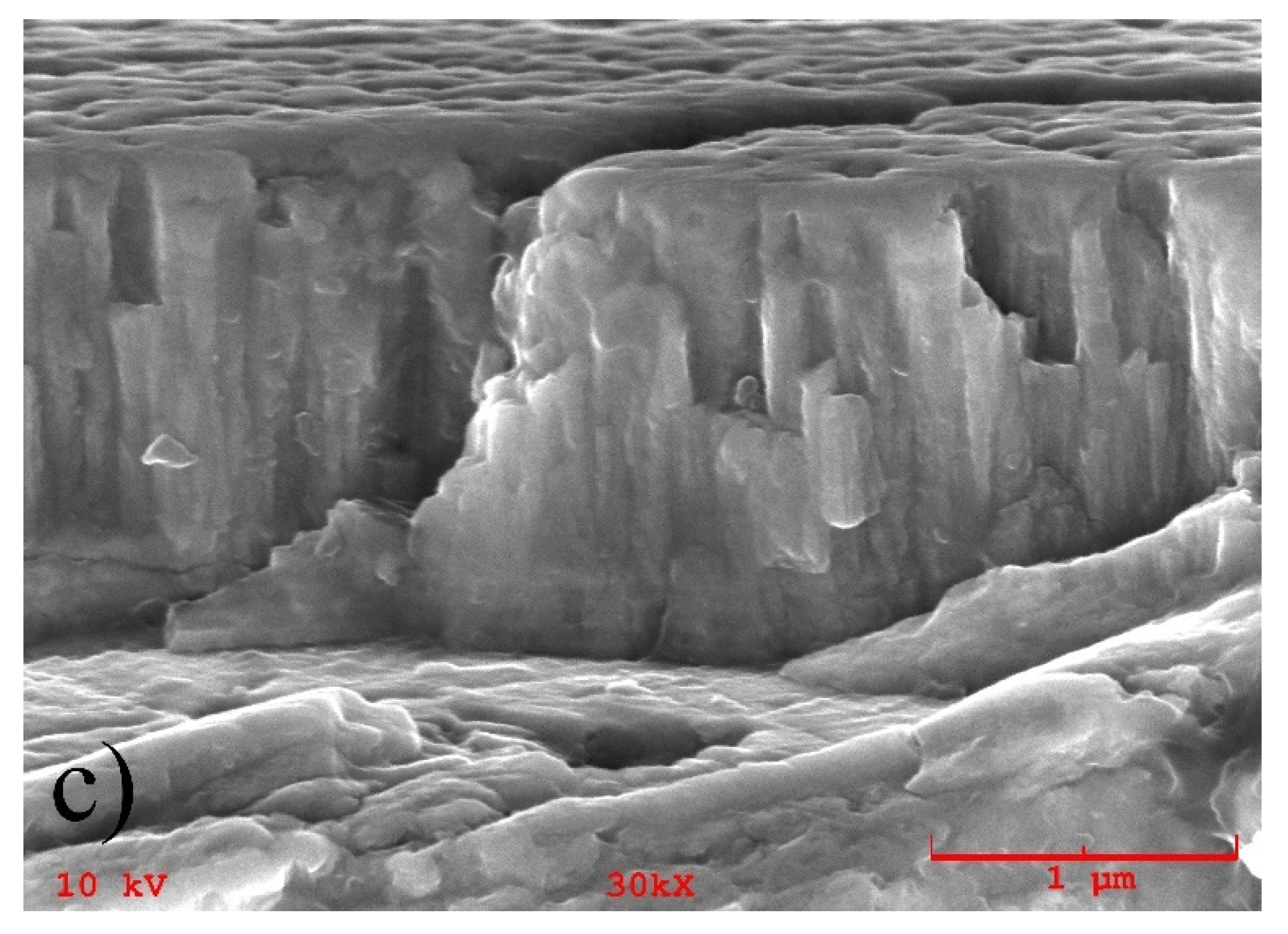
3.1. Composition and Microstructure
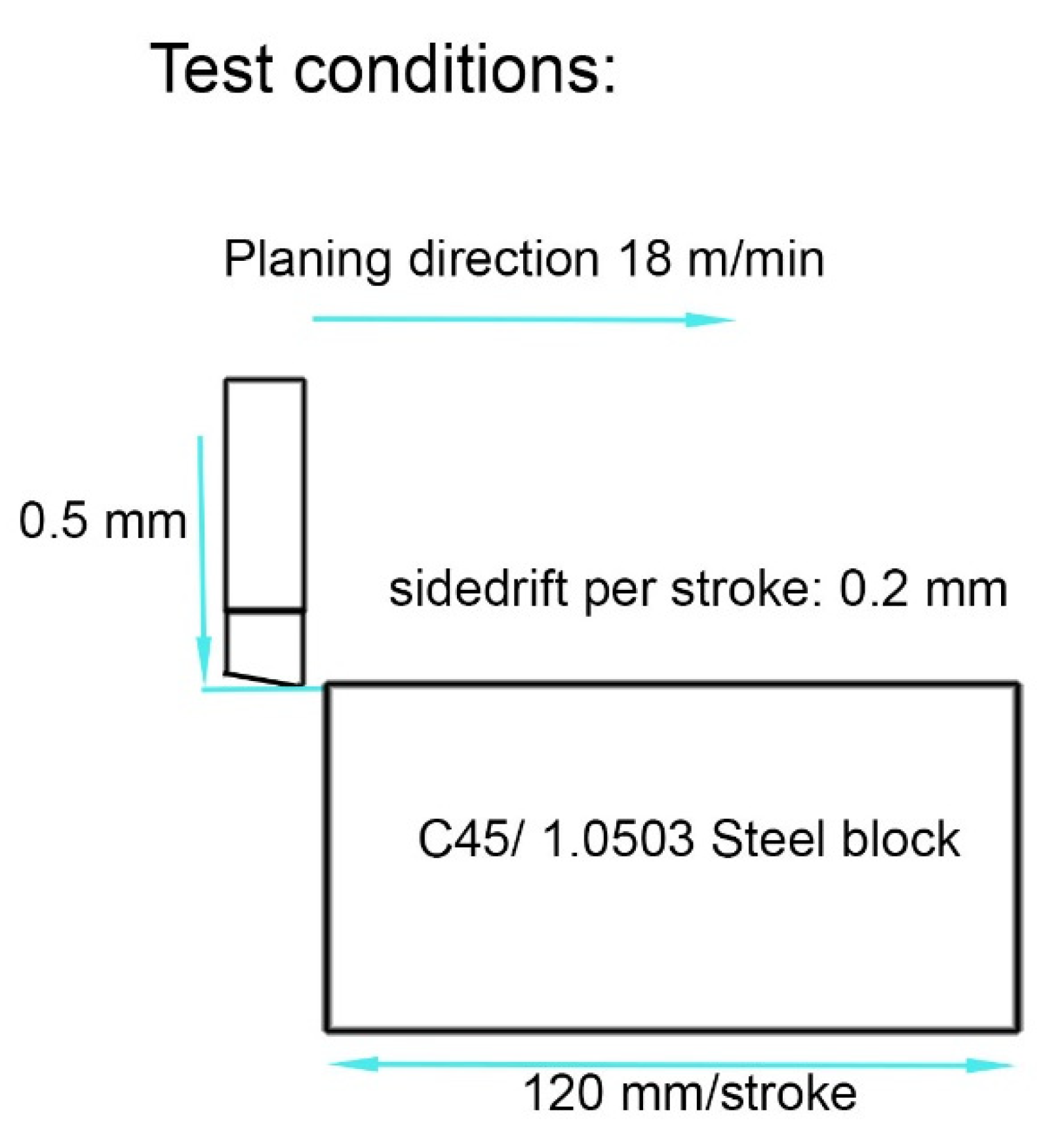
3.2. Typical Tribological Properties
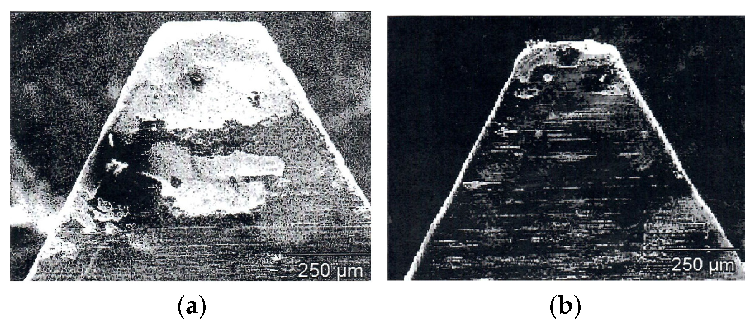
3.3. Examples of First Cutting Tests
4. Conclusions
Author Contributions
Funding
Institutional Review Board Statement
Informed Consent Statement
Data Availability Statement
Acknowledgments
Conflicts of Interest
References
- Broaching (Metalworking). Available online: https://en.wikipedia.org/wiki/Broaching_(metalworking) (accessed on 10 September 2017).
- Oerlikon Balzers GmbH Internet. Plasma-Assisted Coating Processes (Balzers, Liechtenstein). Available online: https://www.oerlikon.com/balzers/global/en/ (accessed on 21 November 2021).
- Münz, W.-D. Titanium aluminium nitride: A new alternative to TiN coatings. J. Vac. Sci. Technol. A 1986, 4, 2117–2225. [Google Scholar] [CrossRef]
- Münz, W.-D. Unbalanced magnetrons: Their impact to modern PVD PVD hard coating equipment. Ann. Technol. Conf. Proc. SVC 1992, 1-878068-11-3, 243. [Google Scholar]
- Mayrhofer, P.H.; Hovsepian, P.E.; Mitterer, C.; Münz, W.-D. Calorimetric evidence for frictional self-adaption on TiAlN/VN superlattice coatings. Surf. Coat. Technol. 2004, 177–178, 341–347. [Google Scholar] [CrossRef]
- PalDaley, S.; Deevi, S.C. Single layer and multilayer coatings of (TiAl)N: A review. Mater. Sci. Eng. A 2003, 324, 58. [Google Scholar] [CrossRef]
- Brown, G.; Feinberg, B.; Galvin, J.E. Multiply stripped ion generation in the metal vapor vacuum arc. J. Appl. Phys. 1988, 63, 4889–4898. [Google Scholar] [CrossRef] [Green Version]
- Schönjahn, C.; Donohue, L.A.; Lewis, D.B.; Münz, W.-D.; Twesten, R.D.; Petrov, I. Enhanced adhesion through local epitaxy of transition-metal nitride coating ferritic steel promoted by metal ion etching in combined cathodic arc/unbalanced mahnetron deposition systems. J. Vac. Sci. Technol. A 2000, 18, 1718–1723. [Google Scholar] [CrossRef]
- Münz, W.-D.; Hauzer, F.J.M.; Schulze, G.; Buil, B. A new concept of physical vapor deposition combining the method of arc evaporation and unbalanced magnetron sputtering. Surf. Coat. Technol. 1991, 49, 161–167. [Google Scholar] [CrossRef]
- Hauzer, F.J.M.; Münz, W.-D.; Schulze, B.J.A.M.B.D.; Tietema, R. Arc Magnetron and the Method of Coating. U.S. Patent US00516095, 3 November 1992. [Google Scholar]
- Münz, W.-D.; Zufrass, T. Industrial scale deposition of well adherent superhard and low friction C-DLC coatings grown by HIPIMS and anode assisted unbalanced magnetron sputtering. Surf. Coat. Technol. 2020, 387, 125485. [Google Scholar] [CrossRef]
- Münz, W.-D. Large Scale Manufacturing of Nanoscale Multilayered Hard Coatings Deposited by Cathodic Arc/Unbalanced Magnetron Sputtering. MRS Bull. 2003, 28, 173–179. [Google Scholar] [CrossRef]
- Münz, W.-D.; Smith, I.J.; Lewis, D.B.; Creasey, S. Dorplet formation on steel substrates during cathodic arc metal ion etching. Vacuum 1997, 48, 473–481. [Google Scholar] [CrossRef]
- Kouznetsov, V.; Macak, M.; Schneider, J.M.; Helmersson, U.; Petrov, I. A novel pulsed magnetron sputter technique utilizing very high target power densities. Surf. Coat. Technol. 1999, 122, 290–293. [Google Scholar] [CrossRef]
- Ehiasarian, A.; New, R.; Münz, W.-D.; Hultman, L.; Helmersson, L.; Kouznetsov, V. Influence of high power densities on the composition of pulsed magnetron plasmas. Vacuum 2001, 65, 147–154. [Google Scholar] [CrossRef]
- EU Growth Project (CRAFT). “NEW CHROME” Cont. Nr. G5ST-CT-2002-530355, Engineering HIPIMS. Coord.: W.-D. Münz.
- Münz, W.-D. HIPIMS: The New PVD Technology, Vacuum’s Best VIP; Wyley-VHC Verlag GmbH & Co. KgaH: Weilheim, Germany, 2008. [Google Scholar]
- Ehiasarian, A.P.; Münz, W.-D.; Hultman, L.; Helmersson, U.; Petrov, I.G. High power pulsed magnetron sputtered CrN films. Surf. Coat. Technol. 2003, 163–164, 267–272. [Google Scholar] [CrossRef]
- Münz, W.-D.; Ehiasarian, A.; Hovsepian, P.E. PVD Coating Process Magnetron Cathodic Sputtering. European Patent EP 1 260 603, 21 May 2002. [Google Scholar]
- Münz, W.-D.; Schenkel, M.; Kunkel, S.; Paulitsch, J.; Bewilogua, K. Industrial Applications of HIPIMS. J. Phys. Conf. Ser. 2008, 100, 082100. [Google Scholar] [CrossRef]
- Paulitsch, J.; Mayrhofer, P.H.; Münz, W.-D.; Schenkel, M. Structure and mechanical properties of CrN/TiN multilayer coatings prepaired by combined HIPIMS/UBM deposition technique. Thin Solid Films 2008, 517, 1239–1244. [Google Scholar] [CrossRef]
- Paulitsch, J.; Schenkel, M.; Zufrass, T.; Mayrhofer, P.H.; Münz, W.-D. Structure and properties of high power impulse magnetron and DC magnetron sputtering CrN and TiN films deposited in an industrial scale unit. Thin Solid Films 2010, 518, 5558–5564. [Google Scholar] [CrossRef]
- OES Was Supplied by: PLASUS—Plasma Monitor and Process Control Systems. Available online: https://www.plasus.de/en/ (accessed on 10 September 2017).
- Pflüger, E.; Schroer, A.; Voumard, P.; Donohue, L.A.; Münz, W.-D. Influence of incorporation of Cr and Y on wear performance of TiAlN coatings at elevated temperatures. Surf. Coat. Technol. 1999, 115, 17–23. [Google Scholar] [CrossRef]
- Hovsepian, P.E.; Lewis, D.B.; Luo, Q.; Münz, W.-D.; Mayrhofer, P.H.; Mitterer, C.; Zhou, Z.; Rainforth, W.M. TiAlN based nanoscale multilayer coatings designed to adapt tribological properties at elevated temperatures. Thin Solid Films 2005, 485, 160–168. [Google Scholar] [CrossRef] [Green Version]
- Zlatanovic, M.; Münz, W.-D. Wear resistance of plasma-nitrided and sputter ion-plated hobs. Surf. Coat. Technol. 1990, 41, 17–30. [Google Scholar] [CrossRef]


| Property | Type 1 | Type 2 | Type 3 |
|---|---|---|---|
| Thickness (µm) | 2.2 | 1.6 | 1.6 |
| Hardness HV | 2000 | 2800 | 2500 |
| Rockwell (class “1” to “6”) | “1” | “1” | “1” |
| Critical load (N) | 49 | 44 | 47 |
| Friction coefficient | 0.73 | 0.7 | 0.93 |
| Ball wear (µm) | 786 | 720 | 1452 |
| Sliding wear rate (10−15 m3/Nm) | 9.08 | 12.91 | 11.43 |
| Type | Actual Coating Time | Total Process Duration |
|---|---|---|
| Type 1 | 105 min | 265–325 min |
| Type 2 | 52 min | 110–270 min |
| Type 3 | 200 min | 350–450 min |
Publisher’s Note: MDPI stays neutral with regard to jurisdictional claims in published maps and institutional affiliations. |
© 2022 by the authors. Licensee MDPI, Basel, Switzerland. This article is an open access article distributed under the terms and conditions of the Creative Commons Attribution (CC BY) license (https://creativecommons.org/licenses/by/4.0/).
Share and Cite
Münz, W.-D.; Klink, R.; Aleksic, D.; Mazaheri, M. HIPIMS/UBM PVD Coating Equipment Designed to Coat Universal Sized Broaches. Coatings 2022, 12, 300. https://doi.org/10.3390/coatings12030300
Münz W-D, Klink R, Aleksic D, Mazaheri M. HIPIMS/UBM PVD Coating Equipment Designed to Coat Universal Sized Broaches. Coatings. 2022; 12(3):300. https://doi.org/10.3390/coatings12030300
Chicago/Turabian StyleMünz, Wolf-Dieter, Roman Klink, Dejan Aleksic, and Mansour Mazaheri. 2022. "HIPIMS/UBM PVD Coating Equipment Designed to Coat Universal Sized Broaches" Coatings 12, no. 3: 300. https://doi.org/10.3390/coatings12030300
APA StyleMünz, W.-D., Klink, R., Aleksic, D., & Mazaheri, M. (2022). HIPIMS/UBM PVD Coating Equipment Designed to Coat Universal Sized Broaches. Coatings, 12(3), 300. https://doi.org/10.3390/coatings12030300