Article

The LiTFSI/COFs Fiber as Separator Coating with Bifunction of Inhibition of Lithium Dendrite and Shuttle Effect for Li-SeS2 Battery
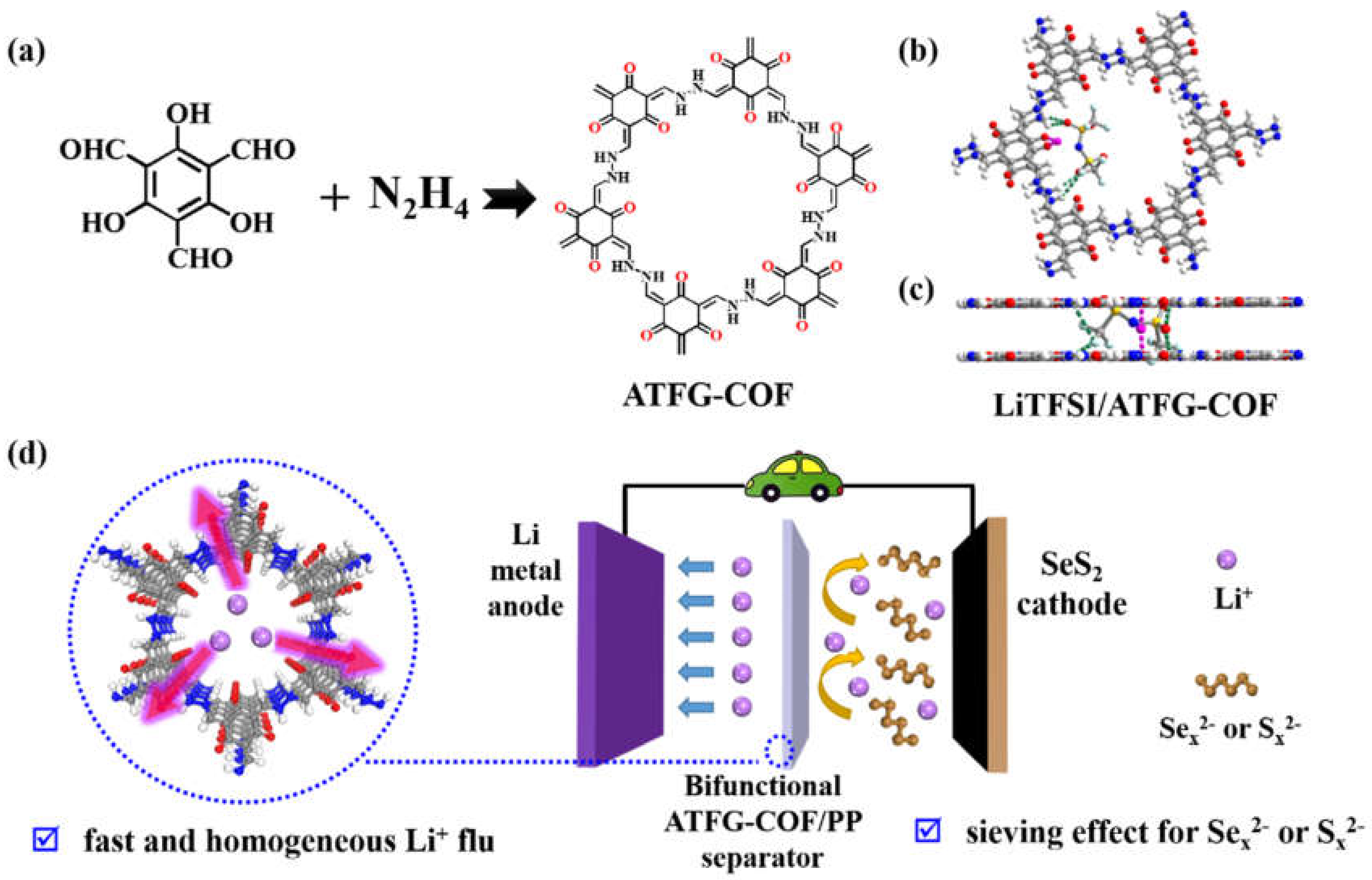
College of Information Engineering, Zhongshan Polytechnic, Zhongshan 528404, China
*
Author to whom correspondence should be addressed.
Coatings 2022, 12(2), 289; https://doi.org/10.3390/coatings12020289
Submission received: 24 January 2022 / Revised: 15 February 2022 / Accepted: 17 February 2022 / Published: 21 February 2022

Abstract

:
The safety problem caused by lithium dendrite of lithium metal anode and the rapid capacity decay problem caused by the shuttle effect of polysulfide and polyselenide during the charge and discharge of selenium disulfide cathode limit the application of lithium selenium disulfide batteries significantly. Here, a fibrous ATFG-COF, containing rich carbonyl and amino functional groups, was applied as the separator coating layer. Density Functional Theory (DFT) theoretical calculations and experimental results showed that the abundant carbonyl group in ATFG-COF had a positive effect on lithium ions, and the amino group formed hydrogen bonds with bis ((trifluoromethyl) sulfonyl) azanide anionics (TFSI), which fixed TFSI in the channel, so as to improve the transfer number of lithium ions and narrow the channels. Therefore, ATFG-COF fiber coating can not only form a rapid and uniform lithium-ion flow on the lithium anode to inhibit the growth of lithium dendrites, but also effectively screen polysulfide and polyselenide ions to suppress the shuttle effect. The Li-SeS2 cell with ATFG-COF/polypropylene (ATFG-COF/PP) separator exhibited good cycle stability at 0.5 C and maintained a specific capacity of 509 mAh/g after 200 cycles. Our work provides insights into the design of dual-function separators with high-performance batteries.

1. Introduction

With the rapid development of portable electronic devices and electric vehicles, it has been difficult to meet their needs with traditional lithium-ion batteries; developing a new-generation energy storage system with high energy density is therefore crucial [1,2,3,4,5,6]. Due to the high theoretical specific capacity and low electrode potential of lithium metal anode, lithium metal batteries are regarded as the next generation of highly specific energy secondary batteries, such as lithium-air batteries, lithium-sulfur batteries, lithium-selenium disulfide (Li-SeS2) batteries, etc. [7,8,9,10,11,12,13]. Selenium disulfide has good electrical conductivity and high theoretical specific capacity, which has led lithium selenium disulfide batteries to attract significant attention from researchers [14,15,16,17]. However, the safety problem of lithium metal anode caused by the lithium dendrite and the rapid capacity decay problem caused by the shuttle effect of polysulfides and polyselenides during the charge and discharge of selenium disulfide cathode have severely limited the application of lithium selenium disulfide batteries.
On the one hand, due to the uneven deposition of lithium ions, lithium dendrites are easily formed during cycles, which can puncture the separator and lead to battery short circuit. In order to reduce the uneven concentration of lithium ions in batteries and alleviate the problem of lithium dendrite, researchers have undertaken many attempts and put forward several effective strategies [18,19,20,21,22,23,24,25,26,27,28,29,30]. For example, some electrolyte additives were developed to regulate the SEI film so as to make the deposition and peeling of lithium ions become uniform; the functional materials were coated on the separator facing the lithium metal anode to induce the even deposition of lithium ions; the three-dimensional fluid collectors with multilevel structures or functional groups were designed to perform as the lithium metal host. On the other hand, in order to suppress the shuttle effect in lithium–selenium disulfide batteries, some porous materials with physical or chemical adsorption to polysulfides or polyselenides were applied as the hosts of the cathode [16,17]. At the same time, as an important part of the battery, the separator is responsible for conducting ions and isolating electrons. The lithium polysulfides or polyselenides produced in the reaction must pass through the separator to shuttle to the anode, which means that the separator modification is also an effective way to inhibit the shuttle [15]. Coating the separator with a layer of functional materials to inhibit the movement of polysulfide or polyselenide ions is a more effective method because of its simple preparation process and stable structure, the light weight of the coating, and reduced impact on the overall energy density of the battery. Therefore, the design of a separator coating that can simultaneously inhibit the growth of lithium dendrite and the shuttle effect of polysulfides/polyselenides will be a major boost for high-performance Li-SeS2 batteries. So far, however, there have been few reports of such functional coatings for Li-SeS2 batteries [31,32,33].
Covalent organic framework (COF) materials are a new type of porous crystalline material, which offer the advantages of stable pore structure and abundant functional groups [34,35,36,37]. Due to the diversity of organically linked units (ligands), the pores of these porous materials have strong chemical modifiability, size, and structure, and adjustable characteristics. Composite materials based on COFs show excellent performance in the field of electrochemical energy storage [38,39,40,41,42]. Through the design of organic linkage units, the pore size and environment of COFs can be adjusted at the molecular level, so as to obtain COFs with screening effect for polysulfides/polyselenides and prevent them from diffusing to the lithium anode. Additionally, polar atoms or groups in the channels have certain adsorption effects on lithium ions, which makes it easier to reduce the concentration gradient caused by the diffusion rate and, consequently, to reduce the possibility of the formation of lithium dendrite.
Based on the above discussion, herein, the fibrous COF, ATFG-COF, which is rich in carbonyl and amino functional groups, was chosen as the separator coating to apply in Li-SeS2 batteries, as shown in Figure 1. Density Functional Theory (DFT) theoretical calculations and experiments showed that the abundant carbonyl group in ATFG-COF has good interaction with lithium ions, which is beneficial to lithium-ion transfer. Besides, the amino group forms hydrogen bonds with TFSI anion, which fixes TFSI in the channel, promotes the separation of electrolyte salts, and improves the migration number of lithium ions. Therefore, the channel of COFs is narrowed, which is conducive to screening polysulfide/polyselenide. Thus, the coating of ATFG-COF fiber has a variety of functions: (1) to effectively induce the uniform deposition and stripping of lithium ions on the lithium anode and inhibit the generation of lithium dendrite; (2) to improve the number of lithium ions transferred; (3) to effectively inhibit the shuttle effect so as to obtain high-performance lithium–selenium disulfide batteries. Compared to previous reports, the fiber ATFG-COF coating is a multi-functional coating that can inhibit both lithium dendrites and shuttle effects, thus improving the performance of batteries [31,32,33].

2. Materials and Methods

2.1. Material Selection

All reagents and chemicals involved in the experiment in this paper were purchased through Merck Sigma-Aldrich, Shanghai, China without further purification.

2.2. Preparation of ATFG-COF Fiber

The ATFG-COF fiber was synthesized according to the reported reference, with some modification [43]. The 2,4,6-trihydroxy-1,3,5-benzenetrialdehyde (18 mg) was placed in a 10 mL threaded headspace bottle. In total, 1 mL 1,4-dioxane and 1 mL mesitylene were added and ultrasonicated for 10 min to fully disperse 2,4,6-trihydroxy-1,3,5-benzenetrialdehyde in the solvent. Next, 0.05 mL hydrazine hydrate was added, and argon was introduced to exclude the air in the bottle. At the same time, a 0.2 mL solution of 6 mol/L glacial acetic acid in water was added to the mixture; the headspace bottle was then sealed and placed in an oven at 120 °C for 72 h. After the reaction, the product was collected and washed with 1,4-dioxane, tetrahydrofuran, and absolute ethanol, respectively.

2.3. Preparation of AB-COF Fiber

The AB-COF fiber was synthesized according to the reported reference with some modification [43]. 1,3,5-benzaldehyde (12 mg) was placed in a 10 mL threaded headspace bottle. A total of 1 mL 1,4-dioxane was added and ultrasonicated for 10 min to fully disperse the 1,3,5-benzaldehyde in the solvent. Next, 0.05 mL hydrazine hydrate was added, and argon was introduced to exclude the air in the bottle. At the same time, 0.5 mL 6 mol/L glacial acetic acid in water solution was added to the mixture; the headspace bottle was then sealed and placed in an oven at 120 °C for 72 h. After the reaction, the product was collected and washed with 1,4-dioxane and absolute ethanol, respectively.

2.4. Preparation of ATFG-COF/PP and AB-COF/PP Separator

The ATFG-COF/PP and AB-COF/PP separators were prepared with the same methode. In total, 30 mg ATFG-COF fiber or AB-COF fiber were ultrasonically dispersed in 30 mL ethanol, which was then filtered through a vacuum pump onto the Celgard-2400 separator. Next, the coated separator was placed in the vacuum-drying oven for 12 h at 55 °C. The dried ATFG-COF/PP or AB-COF/PP separator was cut into 19 mm diameter discs and placed in a glove box (H2O < 0.1 ppm, O2 < 0.1 ppm).

2.5. Preparation of SeS2 Cathode

In total, 0.4 g SeS2 and 0.1 g multiwalled carbon nanotubes (MWCNTs) were mixed uniformly by grinding. The mixture was then sealed in a Teflon-lined, high-pressure reactor and set at 120 °C for 10 h to prepare the SeS2/CNT compound. SeS2/CNT (0.48 g) and super-P (60 mg) were mixed uniformly by grinding and placed into 1.2 g of 5% LA132 binder and 2 mL of 25% n-propanol in water to prepare the slurry. The slurry was mixed uniformly through a high-speed homogenizer and coated on aluminum foil by using a scraper. After drying at 55 °C for 12 h in a vacuum-drying oven, it was cut into a 12 mm diameter disc and placed in a glove box (H2O < 0.1 ppm, O2 < 0.1 ppm).

2.6. Electrochemical Measurements

All electrochemical performances of CR2032 coin cells were evaluated with a LAND CT2001A battery testing system (Wuhan, China). All the coin cells were assembled in the protective atmosphere of a glove box (H2O < 0.1 ppm, O2 < 0.1 ppm) and left for 24 h. For Li-Cu cells, the lithium foil and copper foil were applied as the working electrode with the coating materials facing the copper; for the electrolyte of 1 M lithium bis((trifluoromethyl)sulfonyl)azanide (LiTFSI), 1,3-Dioxolane (DOL): 1,2-Dimethoxyethane (DME) = 1:1 vol% with 1%LiNO3. For Li-Li symmetric cells, the lithium foil was employed as the working electrode with the coating materials facing the lihium foil, and the electrolyte of 1 M LiTFSI, DOL: DME = 1:1 vol% with 1% LiNO3. For Li-SeS2 cells, the SeS2 cathode and lithium anode were assembled with different separator, while the coating materials facing the lithium anode. The cyclic voltammetry test was carried out using CHI660C (Shanghai Chenhua Instrument Co., Ltd, Shanghai, China) electrochemical workstation. The scanning rates of CV curves were 0.1, 0.2, 0.3, 0.4, and 0.5 mV/s, and the potential range was 1.7–2.7 V (vs. Li+/Li). The alternating current impedance (EIS) was tested in a frequency range of 0.01–100,000 Hz. Li-Li symmetric cells were used to test Li+ transfer number by using AC impedance-chronoamperometry. The scan frequency range of AC impedance test was 0.01–100,000 Hz, and the step potential used for constant current polarization was 20 mV.

2.7. Characterization
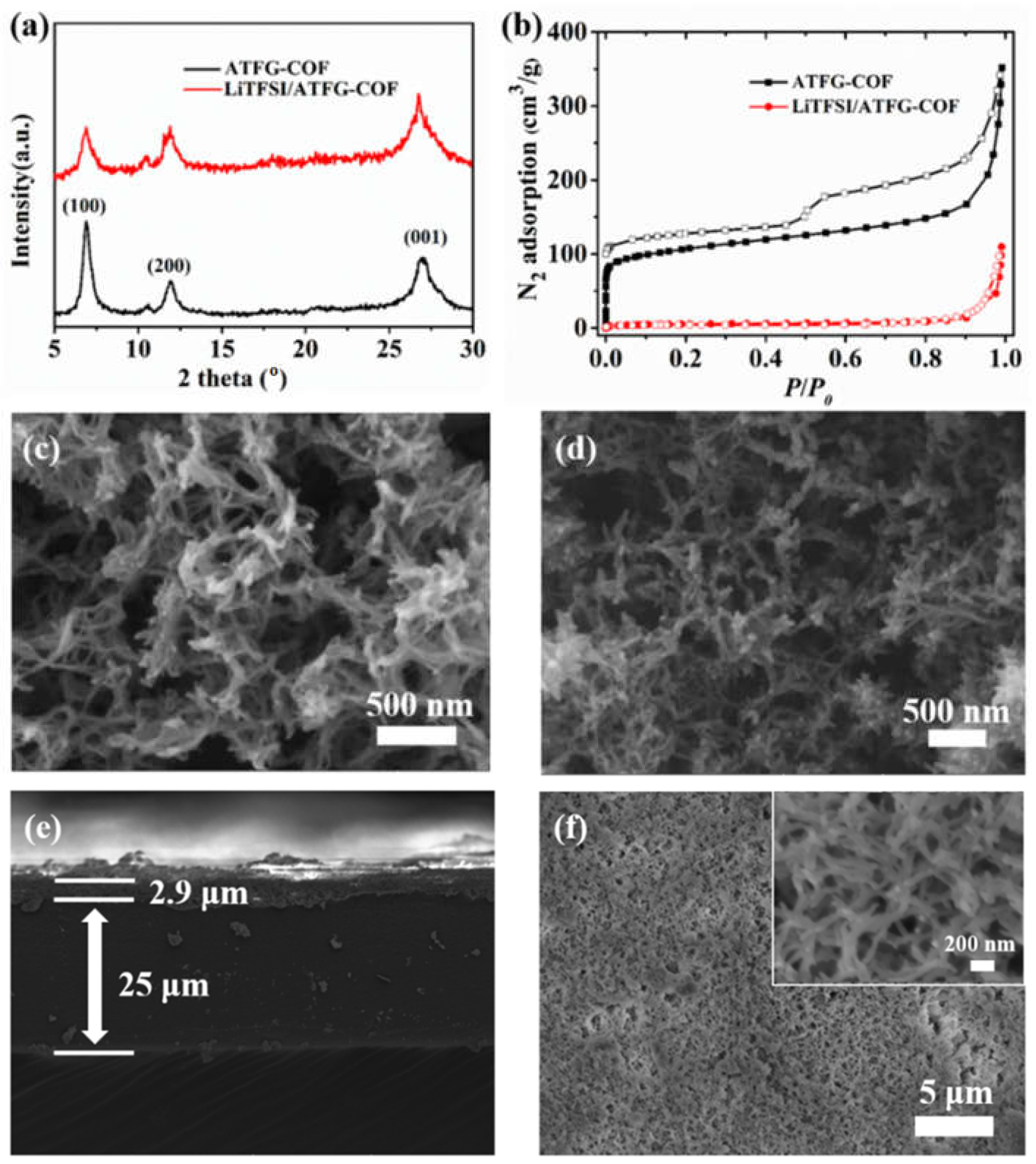
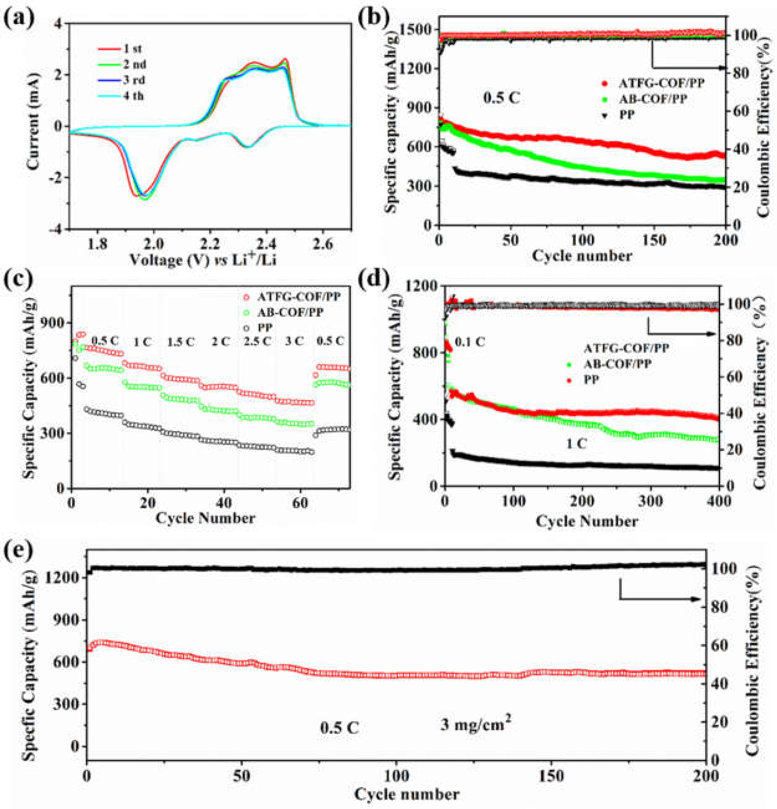
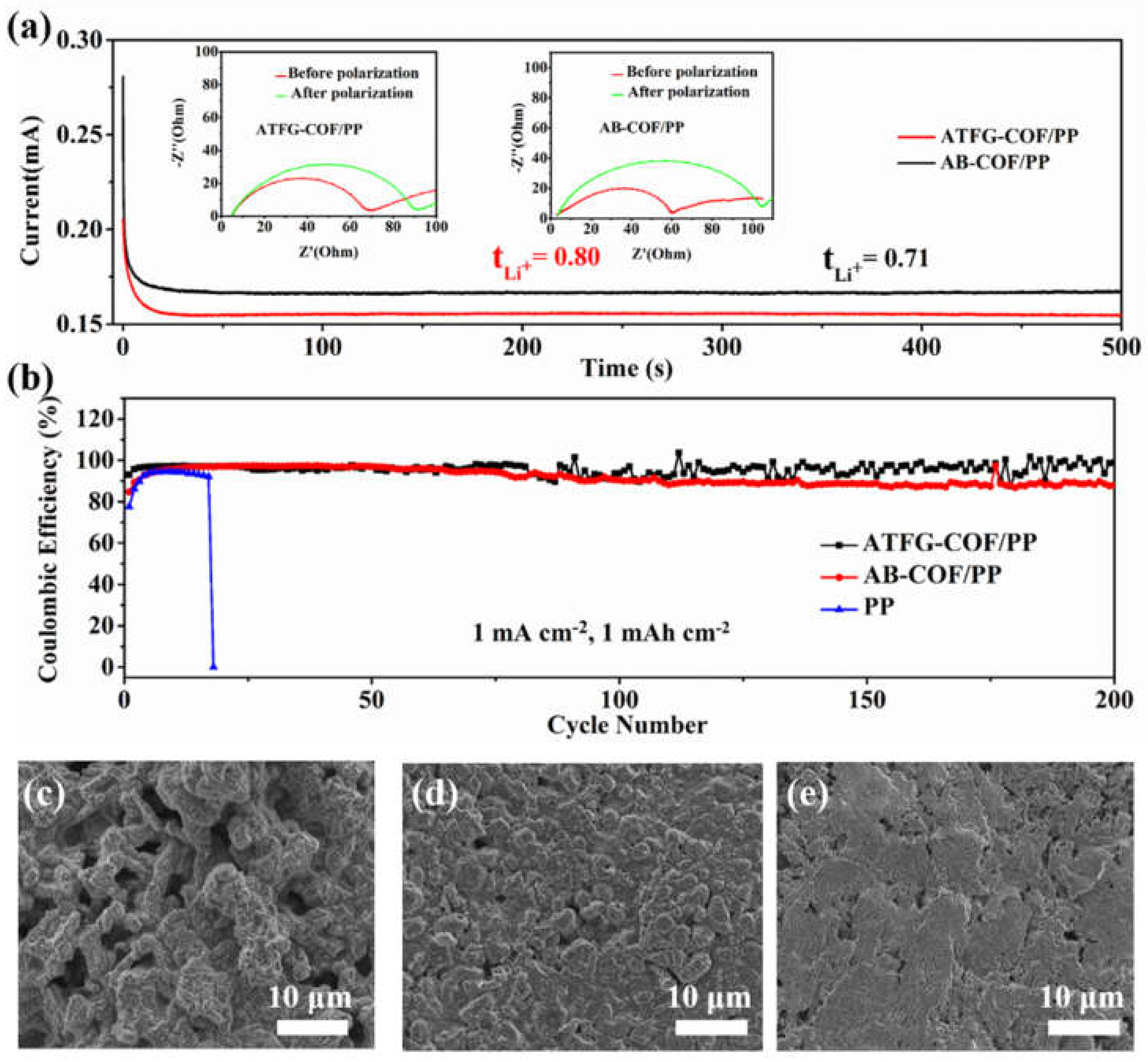
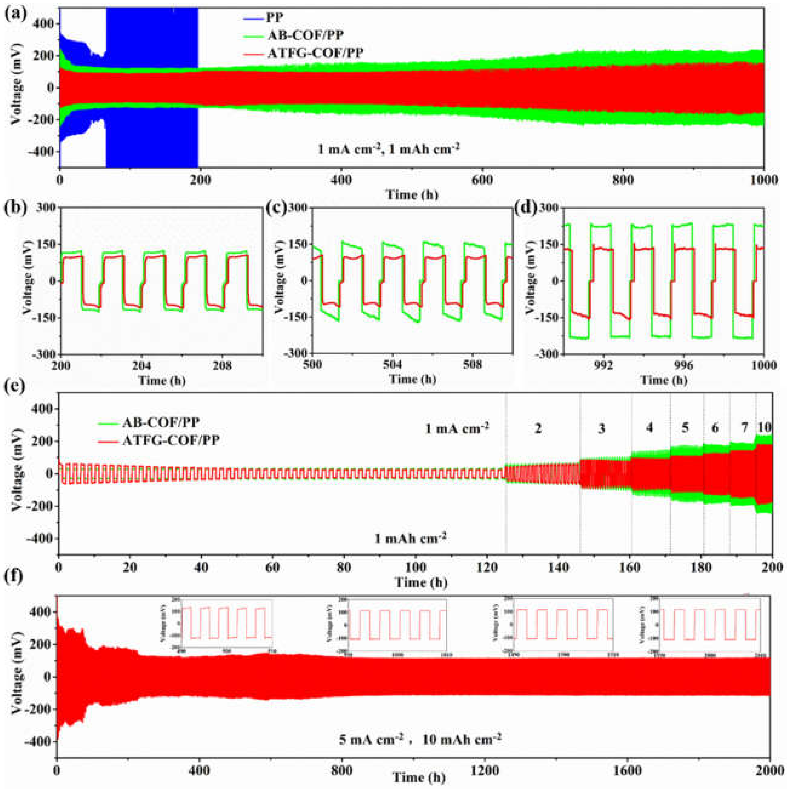
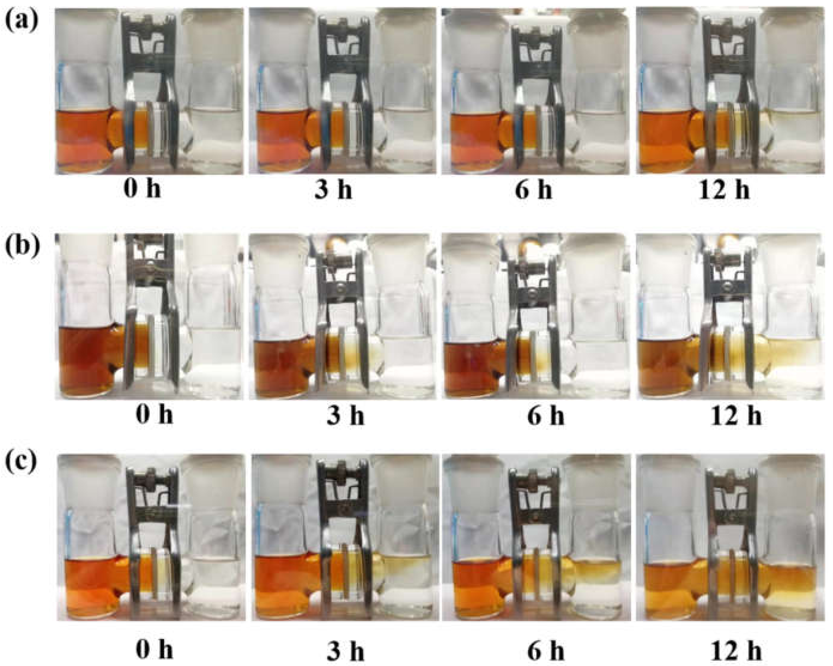
X-ray diffraction (XRD) analysis was performed on a Bruker (Karlsruhe, Germany) D8 Advance X-ray diffractometer employing Cu target tube (λ = 0.154 nm) and a scan voltage of 40 kV with a current of 40 mA at room temperature. Gas absorption/desorption analysis was performed on a BELPREP-vac II (Bel Japan Inc., Osaka, Japan) with extra-high pure N2 (99.999%). The Brunauer-Emmett-Teller (BET) surface and pore volume were calculated according to the N2 absorption/desorption isotherms at 77 K. The morphology and microstructure of the sample were obtained by MAIA3 field-emission microscopy (TESCAN Brno, Brno, Czech Republic).

3. Results

As shown in Figure 1a, ATFG-COF is a COF linked by the imine bonds formed by the reaction of 2,4,6-trihydroxy-1,3,5-benzotriformaldehyde and hydrazine hydrate through a Schiff base. It can be seen from the XRD patterns that the diffraction peaks at 6.9°, 11.8°, and 26.8° corresponded to the crystal planes of (100), (200), and (001) respectively, which is consistent with the reports in previous research (Figure 2a) [43]. The BET test showed that the specific surface area of the ATFG-COF was 383.37 m2/g (Figure 2b) [43]. The SEM image in Figure 2c shows that the synthesized ATFG-COF is a fibrous material with a diameter of tens of nanometers and a length of several microns, which is similar to a previously reported morphology [43]. The DFT calculation showed that the carbonyl group of ATFG-COF can effectively adsorb lithium ions, and that TFSI anions have good interactions with ATFG-COF through hydrogen bonds; therefore, fibrous ATFG-COFs can adsorb LiTFSI (Figure 1b). In order to verify these results, we soaked the ATFG-COF in the solvent of LiTFSI to prepare the LiTFSI/ATFG-COF complex and conduct related characterization. As shown in Figure 2a, even after the adsorption of LiTFSI, the LiTFSI/ATFG-COF still maintained a good crystal shape. The BET test showed that the nitrogen adsorption capacity of LITFSI/ATFG-COF decreased sharply compared with that of the ATFG-COFs with the specific surface area of 5.42 m2/g, indicating that the channel was occupied by the LITFSI (Figure 2b). The SEM showed that the adsorbed LiTFSI/ATFG-COFs still maintained its fibrous structure (Figure 2d).
For comparison, AB-COF, a conformational COF material without a carbonyl group, was synthesized simultaneously. As shown in Figure S1 (in Supplementary Materials), AB-COF was obtained through the reaction of 1,3,5-benzaldehyde and hydrazine hydrate. Compared with the ATFG-COF, the AB-COF did not contain a carbonyl group. As shown in Figure S2, the DFT calculation showed that due to the absence of carbonyl groups, the LiTFSI molecules were only randomly distributed in the AB-COF channel, and there was no obvious interaction between LiTFSI and AB-COF. The XRD patterns showed that AB-COF and ATFG-COF had the same crystal shape, and AB-COF/LITFSI still maintained a good crystal shape after soaking in the solution of LITFSI (Figure S3). The SEM images showed that AB-COF also had a fibrous structure (Figure S4a), while its morphology was maintained after the adsorption of LiTFSI (Figure S4b).
In order to evenly coat ATFG-COF on the separator to prepare the ATFG-COF/PP separator, ATFG-COF fiber was ultrasonically dispersed in ethanol and then coated on the Celgard-2400 (Celgard, Charlotte, NC, USA) by pumping. In Figure 2e, the SEM image of the side view of the ATFG-COF/PP separator shows that the coating thickness is only ~2.9 μm. The SEM image of the side view of the ATFG-COF/PP separator shows that the ATFG-COF fibers uniformly and compactly distributed on the PP separator (Figure 2f). Furthermore, we prepared the AB-COF/PP separator by coating the AB-COF fiber on Celgar-2400 in the same way. Figure S4c,d shows that AB-COF fibers uniformly and compactly coated the membrane with a thickness of ~3 μm.
To confirm that ATFG-COF fiber coating can effectively promote the transport of lithium ions, the separators of ATFG-COF/PP and AB-COF/PP were assembled into a Li-Li symmetric battery, and the lithium-ion transport number was measured. As shown in Figure 3a, the lithium-ion transport number of the ATFG-COF/PP separator was 0.80, while that of the AB-COF/PP separator was 0.71, which were both higher than that of the ordinary PP separator. This is because porous COF can adsorb LiTFSI, thus increasing the transport number of lithium ions. Compared with AB-COF fiber, ATFG-COF fiber has abundant carbonyl groups and amino groups. On the one hand, carbonyl groups can effectively transfer lithium ions; amino groups can form hydrogen bonds with TFSI to fix TFSI in the channel, thus further promoting the transport of lithium ions. Compared with the separator with functional coating, the ATFG-COF/PP also showed a high level of lithium-ion transport [31].
In order to verify that ATFG-COF fiber can induce the uniform transport of lithium ions along the channels, we assembled Li-Cu cells with a series of separators. The coating materials were placed facing the copper foil, so that the lithium ions could be electrodeposited and peeled on the copper foil through the coating. As shown in Figure 3b, the Li-Cu cell with ATFG-COF fiber-coated separator has obvious advantages over the cells, with a coulomb efficiency of 93.6% even after 200 cycles and an average coulomb efficiency higher than 95.8%. For the Li-Cu cell with AB-COF fiber-coated separator, the coulombic efficiency was maintained at the first 50 cycles, and was decreased to 88.6% after 200 cycles, much lower than that of the ATFG-COF coating. Li-Cu cells with PP separators can last less than 20 cycles. Furthermore, we disassembled the Li-Cu cells and observed the deposition of lithium metal on the copper foil. As shown in Figure 3c, in the Li-Cu cell assembled by ordinary PP separator, the lithium metal deposited on the copper foil had a rough and discontinuous surface. After coating with AB-COF, the lithium metal deposited on the copper foil improved and formed complete and continuous lithium metal, but the surface was still rough and uneven (Figure 3d). As ATFG-COF can effectively induce the uniform deposition of lithium ions, the metal lithium deposited on the surface of copper foil is smooth and continuous (Figure 3e).
In order to further verify that ATFG-COF/PP separator can effectively induce the uniform deposition of lithium ions, we assembled the Li-Li symmetric cells with three kinds of separator, ATFG-COF/PP, AB-COF/PP, and PP, for the electrochemical performance test. Figure 4a shows the cycle performance of Li-Li symmetric cells with different separators at 1 mA cm−2 and 1 mAh cm−2. It can be seen that the polarization voltage of Li-Li symmetric cells assembled without any coating layer reached over 500 mV at 90 h, which may have been caused by the lithium dendrite puncturing the separator. By contrast, the Li-Li symmetric cells with the coated separator circulated steadily for up to 1000 h. Among them, the ATFG-COF coating had a smaller and more stable polarization voltage than the AB-COF coating. At 200 h, the polarization voltage of the cells with the AB-COF coating was 135 mV, which gradually increased to 150 mV at 500 h and 200 mV at 1000 h. For ATFG-COF, the polarization voltage was 130 mV at 200 h and slowly rose to 150 mV at 1000 h. Figure 4c shows the rate of performance of the Li-Li symmetric cells with AB-COF/PP and ATFG-COF/PP separators under the capacities of 1 mAh cm−2 and current densities of 1, 2, 3, 4, 5, 6, 7, and 10 mA cm−2. It can be seen that the polarization voltages of the Li-Li symmetric cells with the ATFG-COF-coated separator were smaller at different current densities, indicating that the ATFG-COF fiber coating is more conducive to inducing the uniform deposition of lithium ions. Its good performance can be attributed to the promotion of the homogenous deposition of lithium ions and the reduction in the formation of lithium dendrite by polar groups and uniform channels. Even at higher current density and capacity, the Li-Li symmetric cells with the ATFG-COF/PP separator still showed excellent performance. As shown in Figure 4f, at 5 and 10 mA cm−2, the Li-Li symmetric battery assembled by the ATFG-COF/PP separator still showed a low polarization voltage, around 91 mV, even after a cycle of 2000 h. All these tests indicate that ATFG-COF fiber coating can effectively adsorb LiTFSI and induce the uniform deposition of lithium ions along the channels, thus effectively inhibiting the formation of lithium dendrite.
To prove that ATFG-COF fiber coating can also effectively inhibit the shuttle effect of polysulfides/polyselenides, we carried out sieving experiments on ATFG-COF/PP, AB-COF, and PP separator after the adsorption of LiTFSI. Figure 5a shows the sieving effect with ATFG-COF/PP separator at different times. During this period, the color of the solution on the right side of the H tube basically did not change, indicating that the ATFG-COF coating had a good effect on the sieving of polysulfides/polyselenides. This is because the ATFG-COF channel can effectively fix the TFSI anions, so that the pore size is further reduced, leading to the effective screening of polysulfide/polyselenide anions. As shown in Figure 5b, for the AB-COF/PP separator, there were few polysulfides/polyselenides in the middle of the H tube at 3 h. Until 12 h, the right side of the H tube appeared clear yellow, which was slightly worse than the appearance of the ATFG-COF/PP separator. This is because AB-COF does not have abundant functional groups to fix TFSI, so polysulfides/polyselenides anions pass through slowly. This situation was even worse for the PP separator, which had no barrier to polysulfides/polyselenides anions (Figure 5c).
In general, ATFG-COF fiber coating achieves high lithium ion transport rates, as well as the effective inhibition of lithium dendrite growth and the shuttle effect due to its ability to adsorb LiTFSI. Therefore, we assembled the ATFG-COF/PP separator into Li-SeS2 cells to further evaluate their electrochemical performance. To prove that ATFG-COF fiber coating can also effectively transfer lithium ions in Li-SeS2 cells, we tested the cyclic voltammetry curves of Li-SeS2 cells assembled with different separators at different sweep speeds, and calculated the diffusion coefficient of the lithium ions using the Randle–Sevcik equation. As shown in Figure S5, the cyclic voltammetry curves of all the Li-SeS2 cells have similar REDOX peaks. The reduction peak around 2.3 V is marked as peak A, and the reduction peak around 2.2 V is marked as peak B. Peaks A and B correspond to the conversion of selenium disulfide to lithium polysulfide and lithium polyselenide. The reduction peak (peak C) in the potential range of 1.7–2.1 V is due to the further reduction of polysulfide/polyselenide to Li2S and Li2Se. In the process of oxidation, there are multiple oxidation peaks in the potential range of 2.1~2.5 V, which are called peak D. Peak D potential at ~2.4 V corresponds to the oxidation of Li2Se and Li2S to lithium polysulfide/polysulfide, and then to selenium disulfide. The Randle–Sevcik equation was used to fit the peak currents of A, B, C, and D at different sweep speeds. As shown in Figure S6a–d, peaks A, B, C, and D, respectively, correspond to the CV curves in Figure S5. Under the same peak position and scanning rate, the peak current represents the diffusion coefficient of lithium ion. It can be seen that the lithium ion diffusion coefficient of cells with the ATFG-COF/PP separator in peak A, peak B, and peak D were the highest. In order to further clearly compare the lithium ion diffusion coefficient of different separators at different peak positions, the lithium ion diffusion coefficient and scanning rate were graphed. As shown in Figure S6e,f, the cell with the ATFG-COF/PP separator had the highest lithium ion diffusion coefficient. The results show that the ATFG-COF coating was still able to effectively transfer lithium ions in Li-SeS2 cells.
The CV curve in Figure 6a shows that the Li-SeS2 cells with the ATFG-COF/PP separator had good cycle stability. For further comparison, the cycling performance of the Li-SeS2 cells assembled with different separators, ATFG-COF/PP, AB-COF/PP, and PP, were tested at a current density of 0.5 C. As shown in Figure 6b, the Li-SeS2 cells assembled with the ATFG-COF/PP separator had the highest initial specific capacity, of 824 mAh/g, and showed good cycle stability. For the cells with the PP separator, the initial specific capacity was 639 mAh/g, which rapidly decayed to 384 mAh/g after 15 cycles. Compared with the cell with the PP separator, the specific capacity decay rate of the cell with the AB-COF/PP separator improved, but the performance was still worse than with the ATFG-COF/PP separator. This was because the AB-COF fiber could not effectively suppress the shuttle effect. However, the cells with the ATFG-COF/PP separator could still maintain a specific capacity of 540 mAh/g even after 200 cycles.
Figure 6c shows the rate performances of the Li-SeS2 cells with different separators. The specific capacities of the cells with ATFG-COF/PP separator were 748, 663, 595, 552, 509, and 469 mAh/g when the current densities were 0.5, 1, 1.5, 2, 2.5, and 3 C, respectively. As shown in Figure 6c, the specific capacities of the cells with the ATFG-COF/PP separator were better than those of the cells with the AB-COF/PP separator and PP separator. This was because the ATFG-COF fiber has multiple functions: effectively sieving for polysulfide/polyselenide ions; a high lithium ion transfer number; and inhibiting the growth of lithium dendrite. All of these factors made the cells with the ATFG-COF/PP separator show excellent rate performance. As shown in Figure 6d, at the current density of 1 C for 400 cycles, the specific capacity of the cells with the ATFG-COF/PP separator still remained at 411 mAh/g, which was higher than with the AB-COF/PP and PP separators, with 282 mAh/g and 109 mAh/g, respectively. In order to visually observe the surface of the lithium metal anode, we disassembled the cells with different separators after 400 cycles and carried out an SEM test on the surface of the lithium metal anode. As shown in Figure S7, the surface of the lithium anode in the cell with the PP separator was severely corroded, the lithium metal surface was cracked, and many blocks of dead lithium appeared. This was improved in the cells with the AB-COF/PP separator, but there were still clumps of dead lithium on the surface. By contrast, the surface of the lithium metal anode protected by the ATFG-COF coating showed good flatness, which indicated that ATFG-COF fiber coating can not only effectively promote the uniform deposition and peeling of lithium ions on the surface of lithium metal, but also effectively sieve the polysulfide/polyselenide ions to prevent their corrosion of the lithium metal anode. As shown in Figure 6e, the Li-SeS2 cells with the ATFG-COF/PP separator exhibited good cycle stability at 0.5 C and maintained a specific capacity of 509 mAh/g after 200 cycles, even at a higher SeS2 loading of 3 mg/cm2. The comparison of the performance of the ATFG-COF/PP with the reported materials in Li-SeS2 batteries was added to Table S1 in the revised supporting information. Compared to previous reports, the fiber ATFG-COF coating is a multi-functional coating that can inhibit both lithium dendrites and shuttle effects, thus showing better performance than the SAZ-AF Janus separator [31]. Furthermore, cells with ATFG-COF also showed good performance in the reported Li-SeS2 batteries [31,32,33].

4. Conclusions

Overall, the abundant carbonyl group in ATFG-COF had a positive effect on lithium ions, and the amino group formed hydrogen bonds with bis ((trifluoromethyl) sulfonyl) azanide anionics (TFSI), which fixed TFSI in the channel, thereby improving the transfer number of lithium ions and narrowing the channels. The resultant ATFG-COF/PP can not only form a fast and uniform lithium ion flue on the lithium anode to inhibit the growth of lithium dendrites, but also effectively sieve the polysulfide/polyselenide ions to suppress the shuttle effect. The Li-SeS2 battery assembled with ATFG-COF/PP therefore has a good cycling performance. Even at 5 and 10 mA cm−2, the Li-Li symmetric battery assembled by the ATFG-COF/PP separator still shows a low polarization voltage, around 91 mV, even after a cycle of 2000 h. Furthermore, the Li-SeS2 cell with the ATFG-COF/PP separator exhibited good cycle stability at 0.5 C and maintained a specific capacity of 509 mAh/g after 200 cycles at a higher SeS2 loading of 3 mg/cm2. Our work provides an effective strategy for the simple and efficient enhancement of the performance of Li-SeS2 cells.

Supplementary Materials

The following supporting information can be downloaded at: https://www.mdpi.com/article/10.3390/coatings12020289/s1. Figure S1: The structure of AB-COF; Figure S2: DFT calculation of LiTFSI/AB-COF; Figure S3: XRD spectrum of AB-COF and LiTFSI/AB-COF; Figure S4: SEM pictures of (a) AB-COF and (b) LiTFSI/AB-COF. SEM of AB-COF/PP. (c) Side view and (d) top view; Figure S5: Cyclic voltammograms of Li-SeS2 battery with (a) ATFG-COF/PP, (b) AB-COF/PP, and (c) PP separator at different sweep speeds; Figure S6: Graph of CV peak current versus scan rate. (a) and (b) correspond to the conversion of SeS2 to Li2Sn and Li2Sen, respectively, (c) corresponds to the conversion of Li2Sn and Li2Sen to Li2S and Li2Se, respectively, and (d) represents the corresponding transformation of Li2S and Li2Se to SeS2. The relationship between Li + diffusion coefficient and sweep velocity V of Li-SeS2 battery with ATFG-COF/PP, AB-COF/PP, PP at (e) A peak, (f) B peak, (g) C peak, and (h) D peak; Figure S7: SEM images of lithium metal anodes of the Li-SeS2 cells with different separators after cycles. (a,b) PP, (c,d) AB-COF/PP, (e,f) ATFG-COF/PP separator; Table S1: The comparison of the performance of the ATFG-COF/PP with the reported materials in Li-SeS2 batteries.

Author Contributions

Conceptualization, methodology, J.-H.C., Z.-C.C., Z.-Y.W. and X.-N.Z.; data curation, writing—original draft preparation, writing—review and editing, J.W. and J.-P.K.; project administration, funding acquisition, J.W. and J.-P.K. All authors have read and agreed to the published version of the manuscript.

Funding

This research was funded by Key Research Project of The University (2018KQ04), the Characteristic Innovation (Self-Science) Project of Guangdong Education Department (2020KTSCX331), the Social Public Welfare and Basic Research Project of Zhongshan city (2020B2029), and the Special Fund of Guangdong Science and Technology Innovation Strategy (“Climbing Plan” Special Fund) (PDJH2020A1280, PDJH2021A09), 2021 High-level Talents Research Program (KYG2101).

Institutional Review Board Statement

Not applicable.

Informed Consent Statement

Not applicable.

Data Availability Statement

Data sharing is not applicable to this article.

Conflicts of Interest

The authors declare no conflict of interest.

References

  1. Zheng, Y.; Yao, Y.; Ou, J.; Li, M.; Luo, D.; Dou, H.; Li, Z.; Amine, K.; Yu, A.; Chen, Z. A review of composite solid-state electrolytes for lithium batteries: Fundamentals, key materials and advanced structures. Chem. Soc. Rev. 2020, 49, 8790–8839. [Google Scholar] [CrossRef] [PubMed]
  2. Lee, J.-I.; Song, G.; Cho, S.; Han, D.-Y.; Park, S. Lithium Metal Interface Modification for High-Energy Batteries: Approaches and Characterization. Batter. Supercaps 2020, 3, 828–859. [Google Scholar] [CrossRef]
  3. Liu, S.; Kang, L.; Henzie, J.; Zhang, J.; Ha, J.; Amin, M.A.; Hossain, M.S.A.; Jun, S.C.; Yamauchi, Y. Recent Advances and Perspectives of Battery-Type Anode Materials for Potassium Ion Storage. ACS Nano 2021, 15, 18931–18973. [Google Scholar] [CrossRef] [PubMed]
  4. Hong, X.-J.; Song, C.-L.; Yang, Y.; Tan, H.-C.; Li, G.-H.; Cai, Y.-P.; Wang, H. Cerium Based Metal-Organic Frameworks as an Efficient Separator Coating Catalyzing the Conversion of Polysulfides for High Performance Lithium-Sulfur Batteries. ACS Nano 2019, 13, 1923–1931. [Google Scholar] [CrossRef]
  5. Liu, S.; Kang, L.; Zhang, J.; Jun, S.C.; Yamauchi, Y. Carbonaceous Anode Materials for Non-aqueous Sodium- and Potassium-Ion Hybrid Capacitors. ACS Energy Lett. 2021, 6, 4127–4154. [Google Scholar] [CrossRef]
  6. Tzeng, Y.; Huang, W.-C.; Jhan, C.-Y.; Wu, Y.-H. Effects of In Situ Graphitic Nanocarbon Coatings on Cycling Performance of Silicon-Flake-Based Anode of Lithium Ion Battery. Coatings 2021, 11, 138. [Google Scholar] [CrossRef]
  7. Wang, W.-P.; Zhang, J.; Jia, C.; Yin, Y.-X.; You, Y.; Xin, S.; Guo, Y.-G. Solidifying Cathode-Electrolyte Interface for Lithium-Sulfur Batteries. Adv. Energy Mater. 2021, 11, 2000791. [Google Scholar] [CrossRef]
  8. Hong, X.-J.; Song, C.-L.; Wu, Z.-M.; Li, Z.-H.; Cai, Y.-P.; Wang, C.-X.; Wang, H. Sulfophilic and lithophilic sites in bimetal nickel-zinc carbide with fast conversion of polysulfides for high-rate Li-S battery. Chem. Eng. J. 2021, 404, 126566. [Google Scholar] [CrossRef]
  9. Zhou, H.-J.; Song, C.-L.; Si, L.-P.; Hong, X.-J.; Cai, Y.-P. The development of catalyst materials for the advanced lithium-sulfur battery. Catalysts 2020, 10, 682. [Google Scholar] [CrossRef]
  10. Xiao, Z.; Li, Z.; Li, P.; Meng, X.; Wang, R. Ultrahigh volumetric capacity enabled by dynamic evolutions of host-guest pairs in self-supporting lithium-sulfur batteries. Nano Energy 2020, 70, 104522. [Google Scholar] [CrossRef]
  11. Li, Z.; Xiao, Z.; Li, P.; Meng, X.; Wang, R. Enhanced Chemisorption and Catalytic Effects toward Polysulfides by Modulating Hollow Nanoarchitectures for Long-Life Lithium-Sulfur Batteries. Small 2020, 16, 1906114. [Google Scholar] [CrossRef]
  12. Hong, Y.-S.; Zhao, C.-Z.; Xiao, Y.; Xu, R.; Xu, J.-J.; Huang, J.-Q.; Zhang, Q.; Yu, X.; Li, H. Safe Lithium-Metal Anodes for Li-O2 Batteries: From Fundamental Chemistry to Advanced Characterization and Effective Protection. Batter. Supercaps 2019, 2, 638–658. [Google Scholar] [CrossRef]
  13. Li, Z.; Zhang, J.; Guan, B.Y.; Lou, X.W. Mesoporous Carbon@Titanium Nitride Hollow Spheres as an Efficient SeS2 Host for Advanced Li-SeS2 Batteries. Angew. Chem. Int. Ed. 2017, 56, 16003–16007. [Google Scholar] [CrossRef]
  14. Zhang, Y.; Guo, Y.; Wang, B.; Wei, Y.; Jing, P.; Wu, H.; Dai, Z.; Wang, M.; Zhang, Y. An integrated hybrid interlayer for polysulfides/selenides regulation toward advanced Li-SeS2 batteries. Carbon 2020, 161, 413–422. [Google Scholar] [CrossRef]
  15. Yang, Y.; Hong, X.-J.; Song, C.-L.; Li, G.-H.; Zheng, Y.-X.; Zhou, D.-D.; Zhang, M.; Cai, Y.-P.; Wang, H. Lithium bis(trifluoromethanesulfonyl)imide assisted dual-functional separator coating materials based on covalent organic frameworks for high-performance lithium-selenium sulfide batteries. J. Mater. Chem. A 2019, 7, 16323–16329. [Google Scholar] [CrossRef]
  16. Guo, B.; Yang, T.; Du, W.; Ma, Q.; Zhang, L.-Z.; Bao, S.-J.; Li, X.; Chen, Y.; Xu, M. Double-walled N-doped carbon@NiCo2S4 hollow capsules as SeS2 hosts for advanced Li–SeS2 batteries. J. Mater. Chem. A 2019, 7, 12276–12282. [Google Scholar] [CrossRef]
  17. Chen, T.; Kong, W.; Fan, M.; Zhang, Z.; Wang, L.; Chen, R.; Hu, Y.; Ma, J.; Jin, Z. Chelation-assisted formation of multi-yolk–shell Co4N@carbon nanoboxes for self-discharge-suppressed high-performance Li–SeS2 batteries. J. Mater. Chem. A 2019, 7, 20302–20309. [Google Scholar] [CrossRef]
  18. Zhang, X.-L.; Ruan, Z.-Q.; He, Q.-T.; Hong, X.-J.; Song, X.; Zheng, Q.-F.; Nie, J.-H.; Cai, Y.-P.; Wang, H. Three-Dimensional (3D) Nanostructured Skeleton Substrate Composed of Hollow Carbon Fiber/Carbon Nanosheet/ZnO for Stable Lithium Anode. ACS Appl. Mater. Interfaces 2021, 13, 3078–3088. [Google Scholar] [CrossRef]
  19. Shen, X.; Zhang, R.; Shi, P.; Chen, X.; Zhang, Q. How Does External Pressure Shape Li Dendrites in Li Metal Batteries? Adv. Energy Mater. 2021, 11, 2003416. [Google Scholar] [CrossRef]
  20. Luo, D.; Zheng, L.; Zhang, Z.; Li, M.; Chen, Z.; Cui, R.; Shen, Y.; Li, G.; Feng, R.; Zhang, S.; et al. Constructing multifunctional solid electrolyte interface via in-situ polymerization for dendrite-free and low N/P ratio lithium metal batteries. Nat. Commun. 2021, 12, 186. [Google Scholar] [CrossRef]
  21. Shi, P.; Zhang, X.-Q.; Shen, X.; Zhang, R.; Liu, H.; Zhang, Q. A Review of Composite Lithium Metal Anode for Practical Applications. Adv. Mater. Technol. 2020, 5, 1900806. [Google Scholar] [CrossRef] [Green Version]
  22. Liu, D.-H.; Bai, Z.; Li, M.; Yu, A.; Luo, D.; Liu, W.; Yang, L.; Lu, J.; Amine, K.; Chen, Z. Developing high safety Li-metal anodes for future high-energy Li-metal batteries: Strategies and perspectives. Chem. Soc. Rev. 2020, 49, 5407–5445. [Google Scholar] [CrossRef]
  23. Ye, H.; Zheng, Z.-J.; Yao, H.-R.; Liu, S.-C.; Zuo, T.-T.; Wu, X.-W.; Yin, Y.-X.; Li, N.-W.; Gu, J.-J.; Cao, F.-F.; et al. Guiding Uniform Li Plating/Stripping through Lithium-Aluminum Alloying Medium for Long-Life Li Metal Batteries. Angew. Chem. Int. Ed. 2019, 58, 1094–1099. [Google Scholar] [CrossRef]
  24. Wang, S.-H.; Yue, J.; Dong, W.; Zuo, T.-T.; Li, J.-Y.; Liu, X.; Zhang, X.-D.; Liu, L.; Shi, J.-L.; Yin, Y.-X.; et al. Tuning wettability of molten lithium via a chemical strategy for lithium metal anodes. Nat. Commun. 2019, 10, 4930. [Google Scholar] [CrossRef] [PubMed] [Green Version]
  25. Liang, J.-Y.; Zeng, X.-X.; Zhang, X.-D.; Zuo, T.-T.; Yan, M.; Yin, Y.-X.; Shi, J.-L.; Wu, X.-W.; Guo, Y.-G.; Wan, L.-J. Engineering Janus Interfaces of Ceramic Electrolyte via Distinct Functional Polymers for Stable High-Voltage Li-Metal Batteries. J. Am. Chem. Soc. 2019, 141, 9165–9169. [Google Scholar] [CrossRef] [PubMed]
  26. Zhang, H.; Eshetu, G.G.; Judez, X.; Li, C.; Armand, M. Electrolyte Additives for Lithium Metal Anodes and Rechargeable Lithium Metal Batteries: Progress and Perspectives. Angew. Chem. 2018, 57, 15002–15027. [Google Scholar] [CrossRef] [PubMed]
  27. Zachman, M.J.; Tu, Z.; Choudhury, S.; Archer, L.A.; Kourkoutis, L.F. Cryo-STEM mapping of solid–liquid interfaces and dendrites in lithium-metal batteries. Nature 2018, 560, 345–349. [Google Scholar] [CrossRef] [PubMed]
  28. Lopez, J.; Pei, A.; Oh, J.Y.; Wang, G.-J.N.; Cui, Y.; Bao, Z. Effects of Polymer Coatings on Electrodeposited Lithium Metal. J. Am. Chem. Soc. 2018, 140, 11735–11744. [Google Scholar] [CrossRef]
  29. Liu, Y.; Tzeng, Y.-K.; Lin, D.; Pei, A.; Lu, H.; Melosh, N.A.; Shen, Z.-X.; Chu, S.; Cui, Y. An Ultrastrong Double-Layer Nanodiamond Interface for Stable Lithium Metal Anodes. Joule 2018, 2, 1595–1609. [Google Scholar] [CrossRef] [Green Version]
  30. Duan, H.; Zhang, J.; Chen, X.; Zhang, X.-D.; Li, J.-Y.; Huang, L.-B.; Zhang, X.; Shi, J.-L.; Yin, Y.-X.; Zhang, Q.; et al. Uniform Nucleation of Lithium in 3D Current Collectors via Bromide Intermediates for Stable Cycling Lithium Metal Batteries. J. Am. Chem. Soc. 2018, 140, 18051–18057. [Google Scholar] [CrossRef]
  31. Song, C.-L.; Li, Z.-H.; Ma, L.-Y.; Li, M.-Z.; Huang, S.; Hong, X.-J.; Cai, Y.-P.; Lan, Y.-Q. Single-Atom Zinc and Anionic Framework as Janus Separator Coatings for Efficient Inhibition of Lithium Dendrites and Shuttle Effect. ACS Nano 2021, 15, 13436–13443. [Google Scholar] [CrossRef]
  32. Zhang, J.; Li, Z.; Lou, X.W. A Freestanding Selenium Disulfide Cathode Based on Cobalt Disulfide-Decorated Multichannel Carbon Fibers with Enhanced Lithium Storage Performance. Angew. Chem. Int. Ed. 2017, 56, 14107–14112. [Google Scholar] [CrossRef]
  33. Li, Z.; Zhang, J.; Wu, H.B.; Lou, X.W. An Improved Li–SeS2 Battery with High Energy Density and Long Cycle Life. Adv. Energy Mater. 2017, 7, 1700281. [Google Scholar] [CrossRef]
  34. Zhong, H.; Sa, R.; Lv, H.; Yang, S.; Yuan, D.; Wang, X.; Wang, R. Covalent Organic Framework Hosting Metalloporphyrin-Based Carbon Dots for Visible-Light-Driven Selective CO2 Reduction. Adv. Funct. Mater. 2020, 30, 2002654. [Google Scholar] [CrossRef]
  35. Wang, Z.; Zhang, S.; Chen, Y.; Zhang, Z.; Ma, S. Covalent organic frameworks for separation applications. Chem. Soc. Rev. 2020, 49, 708–735. [Google Scholar] [CrossRef]
  36. Haug, W.K.; Moscarello, E.M.; Wolfson, E.R.; McGrier, P.L. The luminescent and photophysical properties of covalent organic frameworks. Chem. Soc. Rev. 2020, 49, 839–864. [Google Scholar] [CrossRef]
  37. Banerjee, T.; Gottschling, K.; Savasci, G.; Ochsenfeld, C.; Lotsch, B.V.; Gottschling, K.; Savasci, G.; Ochsenfeld, C.; Lotsch, B.V.; Gottschling, K.; et al. H2 Evolution with Covalent Organic Framework Photocatalysts. ACS Energy Lett. 2018, 3, 400–409. [Google Scholar] [CrossRef] [Green Version]
  38. Lu, M.; Zhang, M.; Liu, C.-G.; Liu, J.; Shang, L.-J.; Wang, M.; Chang, J.-N.; Li, S.-L.; Lan, Y.-Q. Stable Dioxin-Linked Metallophthalocyanine Covalent Organic Frameworks (COFs) as Photo-Coupled Electrocatalysts for CO2 Reduction. Angew. Chem. Int. Ed. 2021, 133, 4914–4921. [Google Scholar] [CrossRef]
  39. Zhang, M.; Lu, M.; Lang, Z.-L.; Liu, J.; Liu, M.; Chang, J.-N.; Li, L.-Y.; Shang, L.-J.; Wang, M.; Li, S.-L.; et al. semiconductor/covalent-organic-framework z-scheme heterojunctions for artificial photosynthesis. Angew. Chem. Int. Ed. 2020, 59, 6500–6506. [Google Scholar] [CrossRef]
  40. Chen, D.; Huang, S.; Zhong, L.; Wang, S.; Xiao, M.; Han, D.; Meng, Y. In Situ Preparation of Thin and Rigid COF Film on Li Anode as Artificial Solid Electrolyte Interphase Layer Resisting Li Dendrite Puncture. Adv. Funct. Mater. 2020, 30, 1907717. [Google Scholar] [CrossRef]
  41. Peng, P.; Shi, L.; Huo, F.; Zhang, S.; Mi, C.; Cheng, Y.; Xiang, Z. In Situ Charge Exfoliated Soluble Covalent Organic Framework Directly Used for Zn-Air Flow Battery. ACS Nano 2019, 13, 878–884. [Google Scholar] [CrossRef] [PubMed]
  42. Chen, H.; Tu, H.; Hu, C.; Liu, Y.; Dong, D.; Sun, Y.; Dai, Y.; Wang, S.; Qian, H.; Lin, Z.; et al. Cationic Covalent Organic Framework Nanosheets for Fast Li-Ion Conduction. J. Am. Chem. Soc. 2018, 140, 896–899. [Google Scholar] [CrossRef] [PubMed]
  43. Stegbauer, L.; Hahn, M.W.; Jentys, A.; Savasci, G.; Ochsenfeld, C.; Lercher, J.A.; Lotsch, B.V. Tunable Water and CO2 Sorption Properties in Isostructural Azine-Based Covalent Organic Frameworks through Polarity Engineering. Chem. Mater. 2015, 27, 7874–7881. [Google Scholar] [CrossRef]
Figure 1. (a) Scheme of the structure of ATFG-COF. DFT calculation of the hydrogen bond in LiTFSI/ATFG-COF: (b) Top view and (c) side view. (d) Scheme of bifunctional ATFG-COF/PP separator of inhibition of lithium dendrite and shuttle effect in Li-SeS2 battery.
Coatings 12 00289 g001
Figure 2. (a) XRD pattern and (b) N2 adsorption of ATFG-COF and LiTFSI/ATFG-COF. SEM pictures of (c) ATFG-COF and (d) LiTFSI/ATFG-COF. SEM of ATFG-COF/PP: (e) Side view and (f) top view.
Coatings 12 00289 g002
Figure 3. (a) Lithium-ion transference number measurement of the Li ǁ ATFG-COF/PP ǁ Li and Li ǁ AB-COF/PP ǁ Li; (b) the coulombic efficiency at 1 mAh cm−2 and 1 mA cm−2 of the Li ǁ ATFG-COF/PP ǁ Cu, Li ǁ AB-COF/PP ǁ Cu, and Li ǁ PP ǁ Cu; (ce) SEM images of cycled Li surface morphology at Li ǁ PP ǁ Li, Li ǁ AB-COF/PP ǁ Li, and Li ǁ ATFG-COF/PP ǁ Li after 30 cycles at 1 mAh cm−2 and 1 mA cm−2, respectively.
Coatings 12 00289 g003
Figure 4. (a) Li-Li symmetric batteries with ATFG-COF/PP, AB-COF/PP, and PP at 1 mAh cm−2 and 1 mA cm−2; (bd) amplifying the voltage platform in different cycles; (e) Li-Li symmetric batteries with ATFG-COF/PP, AB-COF/PP and PP at 1 mAh cm−2 and different current densities; (f) Li-Li symmetric batteries with ATFG-COF/PP at 10 mAh cm−2 and 5 mA cm−2.
Coatings 12 00289 g004
Figure 5. The sieving effect experiment: H-tube permeation test with different separators: (a) ATFG-COF/PP, (b) AB-COF/PP, and (c) PP.
Coatings 12 00289 g005
Figure 6. (a) CV curves of the Li-SeS2 cells with ATFG-COF/PP at 0.1 mV s−1; (b) cycle performance, at 0.5 C, of the different separator coatings; (c) rate performance of Li-SeS2 cell with different separator coatings; (d) cycle performance of Li-SeS2 cell with different separator coatings at 1 C; (e) cycle performance of Li-SeS2 cell with different separator coatings at 0.5 C and 3 mg cm−2.
Coatings 12 00289 g006
Publisher’s Note: MDPI stays neutral with regard to jurisdictional claims in published maps and institutional affiliations.

