Article

Improved Cycling Performance of Cation-Disordered Rock-Salt Li1.2Ti0.4Mn0.4O2 Cathode through Mo-Doping and Al2O3-Coating

1
Faculty of Materials Science and Chemistry, China University of Geosciences, Wuhan 430074, China
2
Key Laboratory of Micro-Nano Materials for Energy Storage and Conversion of Henan Province, Institute of Surface Micro and Nano Materials, College of Chemical and Materials Engineering, Xuchang University, Xuchang 461000, China
3
21C Innovation Laboratory, Contemporary Amperex Technology Ltd., Ningde 352100, China
*
Authors to whom correspondence should be addressed.
Coatings 2022, 12(11), 1613; https://doi.org/10.3390/coatings12111613
Submission received: 28 September 2022 / Revised: 19 October 2022 / Accepted: 20 October 2022 / Published: 23 October 2022

Abstract

:
Cation-disordered rock-salt cathode material is a promising material for next-generation lithium-ion batteries due to their extra-high capacities. However, the drawbacks of large first-cycle irreversible capacity loss, severe capacity decay, and lower discharge voltage have undoubtedly hindered their application in commercial systems. In this study, cation doping (Mo4+) and atomic layer deposition (ALD) techniques were used to synthetically modify the Li1.2Ti0.4Mn0.4O2 (LTMO) material to improve the cycling stability. First, the optimal Mo-doped sample (Mo01) with the best electrochemical performance among the different doping amounts was selected for further study. Second, the selected sample was subsequently coated with an Al2O3 layer by the ALD technique to further optimize its electrochemical performance. Results show that the LTMMO/24Al2O3 sample, under optimal conditions, could obtain a specific discharge capacity of up to 228.4 mAh g−1 after 30 cycles, which is much higher than that of the unmodified LTMO cathode material. Our work has provided a new possible solution to address some of the capacity fading issues related to the cation-disordered rock-salt cathode materials.

1. Introduction

At present, the design and development of cathode materials with high specific capacities and good cycling stability have become increasingly important in the research of lithium-ion batteries [1,2,3]. In this case, cation-disordered rock-salt materials have received a great deal of attention due to their extra-high specific capacities. However, these kinds of materials suffer from some disadvantages, including poor cyclability and lower discharge voltage, which limit their further applications [4,5,6,7]. In order to solve the above problems, much work has been carried out by many researchers. Strategies such as elemental doping, heating treatment, voltage window adjustment, and the ALD coating of inert oxides have been used successively to improve the electrochemical performances of cation-disordered rock-salt cathode materials, and satisfactory results have been obtained [8,9]. Currently, most materials are modified in only one aspect. Kazda et al. [10] introduced cations (Mo4+) to improve the initial discharge capacity and high-temperature-cycling capacity of LiMox+yNi0.5−xMn1.5−yO4 cathodes. The results of thermal analysis showed that Mo doping slightly improved the stability of the LiNi0.5Mn1.5O4 crystalline structure, thus improving the stability during high-voltage electrochemical cycles. Liu et al. [11] synthesized and studied a series of Fe3+-doped Li1.2Mn0.6-x/2Ni0.2-x/2FexO2, and showed that suitable Fe doping could significantly improve the cyclic stability and multiplicity of the material. Zhao’s group [12] investigated the electrochemical effects of cation (Sn4+) doping on Li1.2Ni0.2Mn0.8O2, and showed that Sn doping could improve the first-cycle discharge specific capacity, rate performance, and capacity retention of the material for long-term cycles. In addition, the ALD coating of inert oxides was also used to enhance the electrochemical performances of cathode materials. Huang et al. [13] clad an ultrathin Al2O3 film on the surface of Li1.2Ti0.4Mn0.4O2 pore-like particles with the help of the ALD technique. The results showed that the coated material had a higher first-cycle coulombic efficiency and improved cycling stability. Xiao’s team [14] used the ALD technique to coat a protective layer of AlPO4 on the surface of Li1.2Mn0.54Co0.13Ni0.13O2 to combat electrolyte erosion, which improved the first-period coulombic efficiency and thermal stability of the material. Meanwhile, Zhao et al. [15,16,17,18] coated the surfaces of different cathode materials with a metal oxide protective layer with the help of ALD technology, which effectively prevented the electrolyte from eroding the cathode materials and significantly improved the cycling stability of these cathode materials.
In this study, a comprehensive modification strategy was designed to modify Li1.2Ti0.4Mn0.4O2 materials, both with cationic (Mo4+) doping and by coating the materials with Al2O3 film by the ALD technique. Since the ionic radii of Mo4+ are relatively close to those of Mn3+, Ti4+, and Li+, it is theoretically possible to achieve cation doping and keep the primary structure of the raw material unchanged. The experimental results showed that the introduction of Mo ion did not change the structure of the Li1.2Ti0.4Mn0.4O2 material. Meanwhile, a suitable amount of Mo doping could improve the cyclic stability of LTMO. After that, we coated the optimal Mo-doped sample (Mo01) with an Al2O3 layer by the ALD technique to obtain the ultimate specimen under the best experimental conditions, and compared it with the original LTMO cathode material. The results showed that the final sample LTMMO/24Al2O3 under optimal conditions could obtain a specific discharge capacity of up to 228.4 mAh g−1 after 30 cycles, with a capacity retention of 82.5%, which is much higher than that of the unmodified LTMO, with a capacity retention rate of only 14.7%.

2. Experimental

2.1. Preparation of Materials

Li1.2−xTi0.4Mn0.4−xMoxO2 (LTMMO) cathode materials with different Mo doping levels were synthesized using precursors of Li2CO3 (99%, Alfa Aesar, Ward Hill, MA, USA), Mn2O3 (98%, Alfa Aesar), TiO2 (99%, Sigma-Aldrich, St. Louis, MO, USA), and MoO2 (98%, Alfa Aesar), by conventional solid-phase reactions. The precursors were thoroughly mixed by ball-milling for 4 h and pressed into a pellet. Then, the pellet was sintered at 900 °C for 12 h in argon. The obtained material was denoted as LTMMO. Depending on the amount of Mo doping (x), we named the LTMMO samples as Mo00 (LTMO), Mo005, Mo01, and Mo015, corresponding to x = 0, 0.005, 0.010, and 0.015, respectively.
Al2O3 coating was achieved using an Ensure Nanotech ALD system (Atomic layer deposition, LabNano-9100, (Ensure, Beijing, China) [19]. During the ALD process, the as-prepared LTMMO sample was placed in a homemade sample holder, and then the holder was placed in the reaction chamber. The chamber was heated to 200 °C and evacuated to 1.0 mbar. Nitrogen with a flow rate of 20 sccm was used as the carrying and purge gas. Al(CH3)3 and water were employed as aluminum and oxygen precursors, respectively. In a typical ALD cycle, the pulse times of Al(CH3)3 and water were both controlled at 0.02 s. Between each pulse of Al(CH3)3 and water, nitrogen was purged into the chamber for 8 s. For comparison, Al2O3 layers with 16, 24, and 40 ALD cycles were chosen to coat the LTMMO sample. The obtained samples were denoted as LTMMO/nAl2O3, where n stands for the number of ALD cycles.

2.2. Characterization of Materials

Crystal structures of the samples were analyzed by a powder X-ray diffractometer (XRD, D8 Advance, Bruker, Karlsruhe, Germany). Scanning electron microscope (SEM, SU 8010, Hitachi, Tokyo, Japan) and high-resolution transmission electron microscope (HRTEM, F 20, FEI, Eindhoven, Netherland) examinations were performed to explore the morphologies of the samples. X-ray photoelectron spectroscopy (XPS, ESCALab 250Xi, Thermo Scientific, Waltham, MA, USA) with monochromatic Al K-α radiation was conducted to study the element surface states of the samples.

2.3. Electrochemical Experiments

To fabricate an electrode, different Al2O3-coated LTMMO samples and Ketjen black were mixed by ball-milling at 150 rpm for 4 h. The mixture was then manually mixed with polytetrafluoroethylene (PTFE) and rolled into a thin film. The weight ratio of LTMMO/nAl2O3, Ketjen black, and PTFE was 70:20:10. The surface mass density of each electrode film was approximately 4.4 mg cm−2. The cell assembly process was similar to our previous study [20]. A two-electrode wagelok cell was used to test the electrochemical performances of the Al2O3-coated LTMMO thin films. Lithium foil was used as both the working electrode and the counter electrode. The separator was a borosilicate glass fiber membrane (Whatman, Buckinghamshire, UK). The electrolyte was a 1 M solution of LiPF6 dissolved in ethylene carbonate (EC) and dimethyl carbonate (DMC) with a volume ratio of 1:1. All cells were cycled on a LANHE CT2001A system (LAND, Wuhan, China) at room temperature. The potential range was between 1.5 and 4.8 V, and the current density was 10 mA g−1. The electrochemical impedance spectroscopy (EIS) measurements were performed on Gamry Reference 3000 equipment (Gamry, Warminster, PA, USA). Cyclic voltammetry (CV) was carried out within 1.5–4.8 V on a CHI760E electrochemical workstation (CH Instruments, Shanghai, China) with a scanning rate of 0.5 mV s−1.

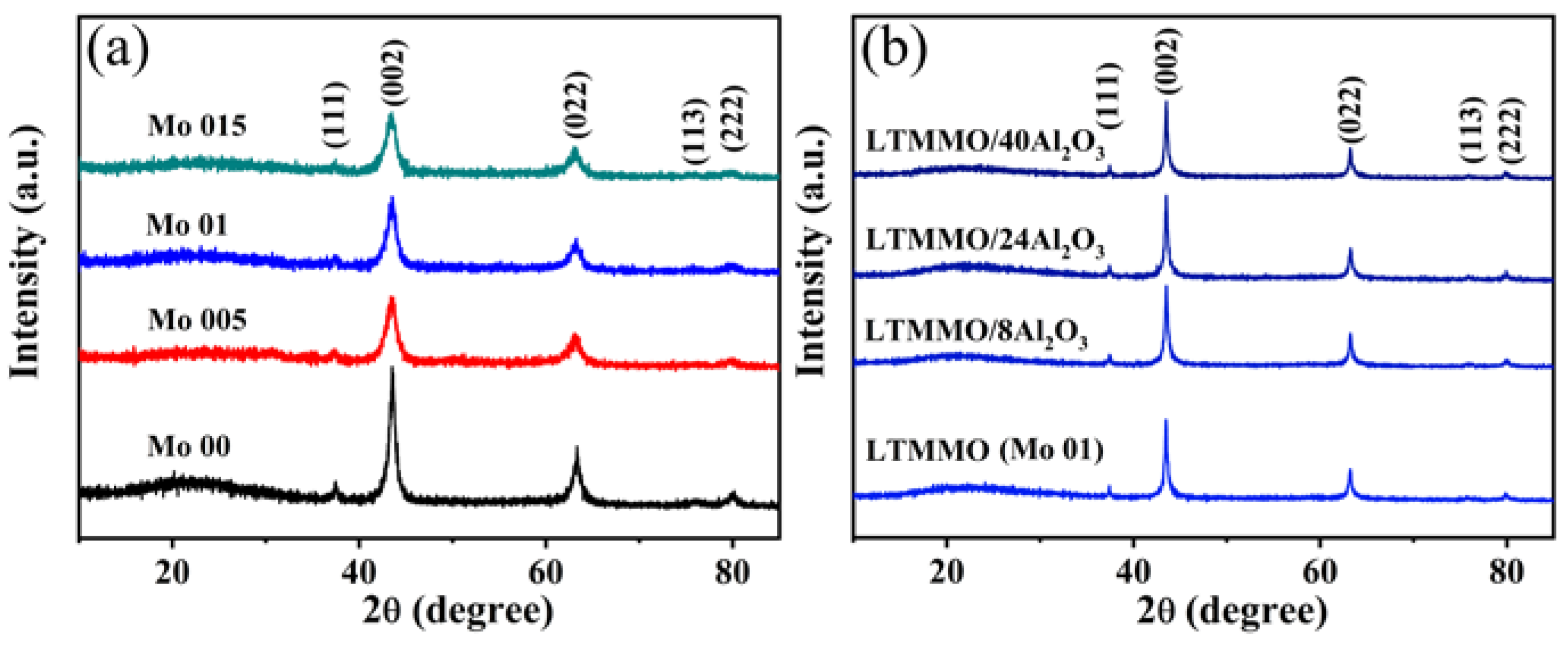
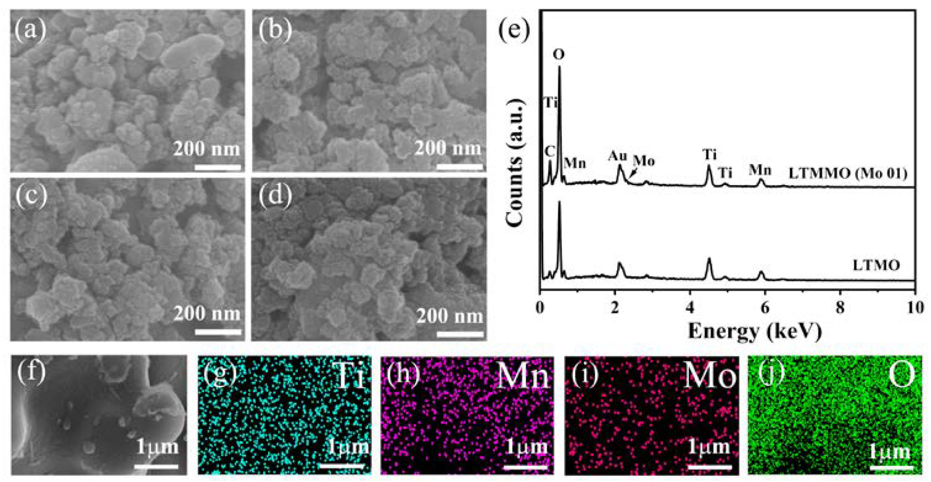
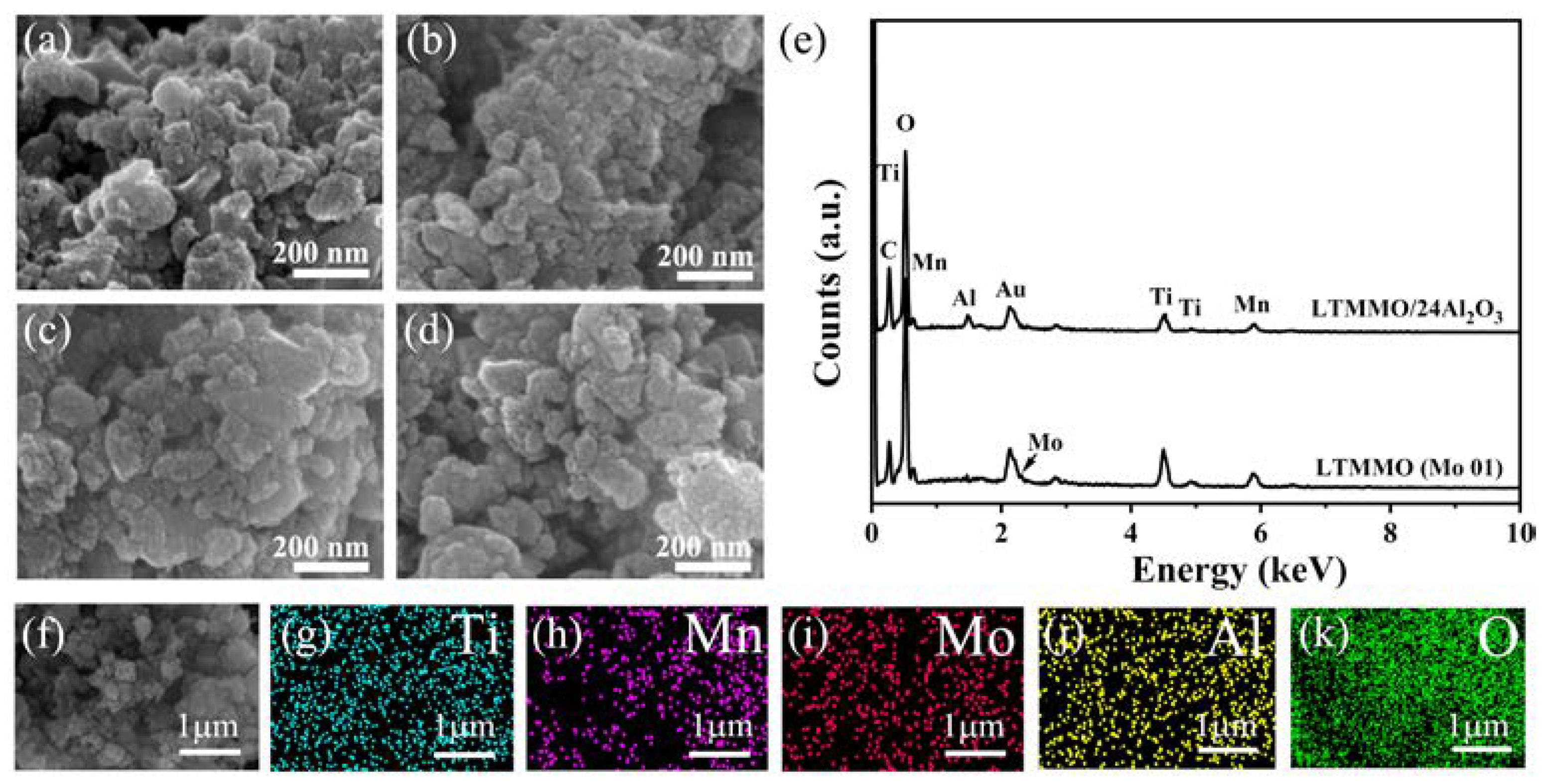
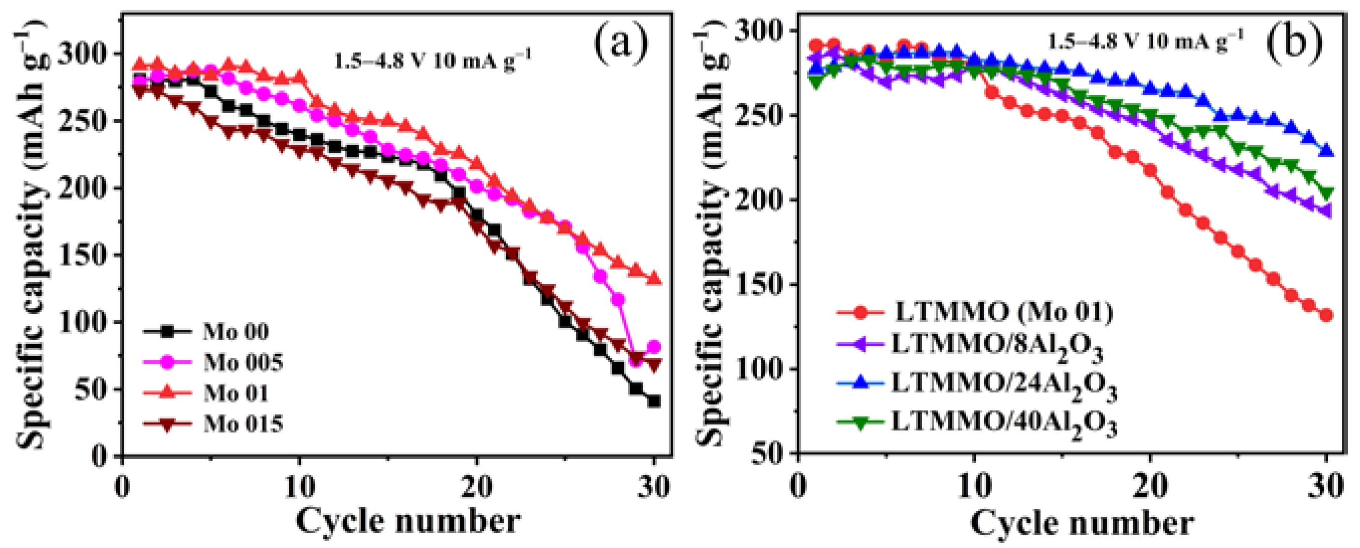
3. Results and Discussion

Figure 1a shows the crystal structures of the synthesized LTMMO samples after they were ball-milled with Ketjen black (KB), and the XRD peaks of all samples match well with the characteristic peaks of the cation-disordered rock-salt structure. Figure 1b shows the XRD patterns of different LTMMO/nAl2O3 samples. As can be seen, all the diffraction peaks of LTMMO correspond to the characteristic diffraction peaks of the cation-disordered rock-salt structure [21]. This result indicates that the ALD coating did not change the structure of LTMMO samples. Besides, no Al2O3 diffraction peaks were detected in the LTMMO/nAl2O3 samples, and the reason may be that the amount of coated Al2O3 was too small or the coated Al2O3 was amorphous.
The morphologies of the above samples are shown in Figure 2. From Figure 2a, it can be seen that the undoped Mo sample (Mo00) agglomerated into micro-nanoparticles with small primary particles of less than 100 nm. The morphologies of the Mo-doped samples were almost unchanged, as shown in Figure 2 b–d. It is known that a smaller particle size facilitates the diffusion of lithium ions and electrons, which may lead to better electrochemical properties. The elemental compositions of the Mo00 sample and Mo01 sample were analyzed by an energy-dispersive spectrometer, as shown in Figure 2e. Only three elements, Mn, Ti, and O, were detected in the Mo00 sample. In contrast, the EDS spectrum of the Mo01 sample shows the characteristic peaks of Mo in addition to those of Mn, Ti, and O, indicating the presence of Mo in the Mo01 sample. At the same time, the elemental distribution of the Mo01 sample was further analyzed by elemental mapping experiments. Ti, Mn, O, and Mo elements were uniformly distributed in the Mo01 sample, which affirms that Mo was indeed present in the Mo01 sample. At the same time, SEM images of the Mo-doped Mo01 sample without and with ALD coating are shown in Figure 3. As can be seen in Figure 3a, the morphology of the Mo01 sample was similar to that of the Mo00 sample. After the ALD coating with Al2O3, the morphologies and sizes of the samples remained almost unchanged, as shown in 3 b, c, and d. Due to the small sizes of the coated Al2O3 particles and the thinness of the Al2O3 layer (with a thickness of only a few nanometers), the changes in the morphology of the Mo01 before and after coating could not be clearly observed by SEM. The differences in the elemental composition of the two samples before and after coating are shown in Figure 3e. From the spectrum it is obvious that only four elements, Mn, Mo, Ti, and O, were detected in the original LTMMO sample. In contrast, the EDS spectrum of LTMMO/24Al2O3 shows the characteristic peaks of the Al element, affirming the existence of Al in the coated sample. The elemental mapping results shown in Figure 3f demonstrate the homogenous dispersion of Ti, Mn, Mo, O, and Al elements in the LTMMO/24Al2O3 sample.
Figure 4a shows the cycling performances of the LTMMO samples with different Mo doping contents. It can be seen that the first discharge capacity of the Mo00 sample was 280.6 mAh g−1 at x = 0. After 30 cycles, the capacity decayed to 41.2 mAh g−1 with a capacity retention of only 14.6%. At x = 0.005, the first discharge capacity of sample Mo005 was 278.5 mAh g−1, and it decayed to 81.4 mAh g−1 after 30 cycles, with a capacity retention of approximately 29.2%. It is worth mentioning that when x increased to 0.01, the first discharge capacity of sample Mo01 was 291.2 mAh g−1. After 30 charge/discharge cycles, its discharge capacity was 131.8 mAh g−1, with a capacity retention of 45.2%. However, the electrochemical performance of sample Mo015 deteriorated significantly by increasing the value of x. After 30 cycles, the discharge capacity was only 69.03 mAh g−1, with a capacity retention of 25.3%. It can be intuitively deduced that doping with Mo can stabilize the structure of LTMMO material to some extent. In order to further enhance the electrochemical properties of the LTMMO material, we used the ALD technique to clad a thin film of Al2O3 onto the surface of the preferable LTMMO particles (Mo01), which was superior to the other LTMMO samples, to protect the LTMMO material from the erosion of the electrolyte during the charge/discharge cycles.
The electrochemical properties of LTMMO/nAl2O3 samples were also investigated. Figure 4b shows the cycling stabilities of the uncoated and Al2O3-coated LTMMO (Mo01) samples at a current density of 10 mA g−1. Interestingly, the discharge capacities of all samples tended to increase gradually in the first few cycles and decreased gradually, which may have been due to the activation process of the materials in the first few cycles. A similar experimental phenomenon has been reported in the literature for other cathode materials [22]. The initial discharge capacity of the original LTMO (Mo00) was 280.3 mAh g−1, and after 30 cycles the specific capacity decayed rapidly to 154.5 mAh g−1, with a capacity retention of approximately 55.1%. When the number of ALD coating cycles of Al2O3 was eight, the first discharge capacity of sample LTMMO/8Al2O3 was 283.7 mAh g−1, and after 30 charge/discharge cycles, the discharge capacity was only 193.6 mAh g−1, with a capacity retention of 68.2%. It is worth mentioning that after increasing the number of ALD cycles of Al2O3, the first discharge capacity of LTMMO/24Al2O3 was 277.0 mAh g−1, and after 30 charge/discharge cycles the discharge capacity was still as high as 228.4 mAh g−1 with a capacity retention rate of 82.5%—55% higher than that of uncoated LTMMO. However, with an increasing number of ALD cycles of Al2O3, the discharge capacity of LTMMO/40Al2O3 decreased to only 204.5 mAh g−1 after 30 cycles, with a capacity retention of approximately 75.7%. The excessively thick insulating Al2O3 cladding layer hindered lithium-ion transportation and reduced the electrochemical performance of the material. By combining the above results, it can be concluded that in order to achieve the best performance, the optimum Mo doping amount (x) is 0.01, and the optimum number of ALD cycles of Al2O3 is 24. In the following part, the sample obtained under this condition is named LTMMO/24Al2O3.
In order to directly observe the Al2O3 layer on the surface of the LTMMO particles, the differences between the microstructures of the original LTMMO and the LTMMO/24Al2O3 samples were characterized and analyzed by high-resolution transmission electron microscopy (HR-TEM), and the results are shown in Figure 5b. Clear lattice fringes can be seen in both the bulk phase and the surface region of the LTMMO material (Figure 5a). In contrast, the LTMMO/24Al2O3 particles still had obvious lattice fringes in the bulk phase, but the morphology of the surface had changed significantly. A dense, amorphous layer with a thickness of about 2–3 nm was clearly observed in the surface region (Figure 5b). Based on the above results, we infer that the layer might be the Al2O3 cladding layer.
XPS was used to analyze the chemical compositions of samples LTMO, LTMMO (Mo01), and LTMMO/24Al2O3, as well as the chemical valence states of the elements. All spectra were calibrated with an exotic C1s peak (284.6 eV). Figure 6a shows the full elemental XPS spectra of the three samples, from which it can be seen that the three samples contained characteristic peaks of Ti, Mn, and O elements. A closer look at the full spectra of the three samples, from the partial enlargement (inset of Figure 6a), revealed that the LTMMO (Mo01) sample had the characteristic peaks of Mo, and the LTMMO/24Al2O3 sample had not only the peaks of Mo but also the characteristic peaks of Al, while the original LTMO sample contained characteristic peaks of neither Mo nor Al. The XPS binding energies of Ti 2p3/2 and Ti 2p1/2 were located at 457.9 eV and 463.7 eV (Figure 6b), corresponding to Ti4+ ions in other Ti-based compounds [23]. The peaks located at 641.4 eV and 653.3 eV (Figure 6c) in the Mn 2p XPS spectra of LTMO, LTMMO (Mo01), and LTMMO/24Al2O3 samples were the characteristic peaks of 2p3/2 and 2p1/2 of Mn3+ [24,25]. In addition, the peak located at 642.8 eV corresponded to the characteristic peak of Mn4+ 2p3/2 [26,27]. The Mn4+ in the samples may have been due to the partial oxidation of Mn3+ on the sample surface. Figure 6d shows the Mo 3d XPS patterns of the three samples, and it is obvious that no peaks of Mo appear in the XPS pattern of the LTMO sample. In contrast, the peaks of the LTMMO (Mo01) and LTMMO/24Al2O3 samples located at 232.6 eV corresponded to the characteristic peaks of 3d3/2 of Mo4+, respectively [28,29,30]. As for the Mo6+ in the samples, it could have come from the oxidation of Mo4+ on the sample surface [31]. Figure 6e shows that the XPS spectrum of O 1s consisted of two parts, where the peak at 529.1 eV corresponds to the binding energy of M-O where (M: Mn, Ti, and Mo), while the peak at 531.1 eV corresponds to the binding energy of the CO32− anion group and Al-O. No Al peak appears in the XPS spectrum of the LTMMO (Mo01) sample, while the XPS spectrum of Al 2p3/2 at 74.9 eV of the LTMMO/24Al2O3 sample could be observed in the LTMMO/24Al2O3 spectrum [32]. Based on the above results, the chemical composition of the surface coating layer of the LTMMO/24Al2O3 sample was probably Al2O3, which indicates that an Al2O3 layer was successfully coated on the surface of the LTMMO particles by the ALD technique.
A comprehensive comparison of the electrochemical properties of the LTMMO/24Al2O3 sample with LTMMO (Mo01) and the original sample LTMO is presented below. Figure 7 shows the charge/discharge curves and coulombic efficiencies for three samples at a current density of 10 mA g−1. The first 30 turns of the charge/discharge curve (plotted every five cycles) and the charge/discharge cycles after 30 cycles are plotted. As shown in Figure 7 a–c, the first charge/discharge curves of all samples have the same shape, and none of them indicate a 4.5 V charging voltage plateau, indicating that the LTMMO (Mo01) and LTMMO/24Al2O3 samples still maintained the cation-disordered rock-salt structure and the charge/discharge curves remained unchanged. After 30 cycles, the discharge voltage plateau of LTMO was significantly lower than that of LTMMO (Mo01) and LTMO/24Al2O3 samples, and its discharge capacity was also much lower than that of the other two samples, as shown in Figure 7. It can be deduced that the coating of Al2O3 might have improved the discharge voltage plateau and the specific capacity of the material after long cycles. As shown in Figure 7d, the first discharge capacity of LTMO was 286.3 mAh g−1, and it decayed rapidly to 41.5 mAh g−1 after 30 charge/discharge cycles, with a capacity retention of only 14.7%. The discharge specific capacity of LTMMO (Mo01) was 291.6 mAh g−1 in the first cycle. After 30 charge/discharge cycles, it had a discharge capacity of 131.8 mAh g−1, with a capacity retention of 45.3%. The first discharge specific capacity of LTMMO/24Al2O3 was 277.0 mAh g−1, while after 30 cycles, the sample could still deliver a discharge capacity as high as 228.4 mAh g−1 with a capacity retention of 82.5%. It was reported that capacity fading might come from the mild irreversible phase transformation of LTMO and slight decomposition of the electrolyte at high voltages (4.8 V). Our results suggest that Mo doping and further coating of a proper thickness of the Al2O3 layer by the ALD technique may reduce the impacts of the above two deficiencies.
Figure 8 shows the cyclic voltammetry curves of the LTMO, LTMMO (Mo01), and LTMMO/24Al2O3 samples for the first three cycles. During the anodic oxidation process, the LTMO sample had two anodic oxidation peaks (Figure 8a), one of which was located at ~3.99 V, corresponding to the Mn3+ to Mn4+ oxidation reaction [33]. Another anodic oxidation peak at ~4.71 V corresponded to the oxidation reaction of O2− (oxygen loss from the crystal structure and oxidation of O2− to form O22− or O2); similar results are often seen in the CV curves of layered lithium-excess cathode materials [34]. However, this anodic oxidation peak at 4.71 V disappeared in the second and third cycles, indicating poor reversibility of the oxidation reaction of O2− in the LTMO samples. In the cathodic reduction process, the reduction peak located at about 2.81 V corresponded to the Mn4+ to Mn3+ reduction reaction [35]. It is clear from Figure 8a that this reduction peak clearly shifted toward a lower potential in the subsequent cycles, suggesting that the reduced manganese ion may have had a chemical valence lower than +3. The CV curve of LTMMO (Figure 8b) had two distinct differences compared to that of LTMO. The most obvious difference was that the anodic oxide peak located at ~4.51 V in the first cycle was still present in the subsequent second and third cycles, indicating that the loss of lattice oxygen in the LTMMO material was more moderate than in LTMO. Additionally, the cathodic reduction peak located at about 3.08 V did not shift as distinctly in the second and third cycles as LTMO, indicating that the valence state of Mn ion in LTMMO remained at +3 after reduction. Figure 8c shows that the CV curves of LTMMO/24Al2O3 had several significant differences compared to LTMO and Mo01. Firstly, the anodic oxidation peak corresponding to the oxidation reaction of O2− was still clearly visible after three cycles, indicating that the loss of lattice oxygen in the LTMMO/24Al2O3 sample was significantly suppressed and the reversibility of the redox reaction of O2− greatly increased. Secondly, the cathodic reduction peak seemed more stable than the other two samples, indicating that the LTMMO/24Al2O3 sample had a higher structural stability during the charging and discharging cycles. The magnitude of the potential difference between the anodic oxidation peak and the cathodic reduction peak in the first CV curve was closely related to the high reversibility of the electrode material [36]. Comparing the CV curves, it is clear that the potential difference of LTMMO/24Al2O3 (0.69 V) was much smaller than that of LTMO (1.25 V), indicating that LTMMO/24Al2O3 had a higher reversibility.
To further investigate the intrinsic reasons for the effects of doped cationic Mo and Al2O3 coating on the electrochemical properties of LTMO materials, the electrochemical impedances of three samples in the de-lithiated state were investigated. The Nyquist curves for the LTMO sample were simulated by the equivalent circuit diagram shown in the inset in Figure 9a. While the curves of the latter two samples present a depressed semicircle from high- to middle-frequencies and a sloping line in the low-frequency region, they can be simulated by the equivalent circuit diagram shown in the inset in Figure 9c. In the equivalent circuit diagram, R1 represents the ohmic resistance, and the semicircle in the mid-low frequency region represents the charge-transfer response and consists of the charge-transfer resistance (R2) and the CPE1 connected in parallel with it. The diagonal line represents the Warburg impedance (W1). The fitted impedance parameters of the electrodes are displayed in Table 1. It can be seen that the charge-transfer resistance of the LTMO (Mo01) electrode was small (291.0 Ω) before cycling, and increased to 384.2 Ω and 3762 Ω for one and five cycles, respectively. However, the LTMO electrode showed larger charge-transfer resistances of 423.5 Ω (before cycling), 963.8 Ω (one cycle), and 34547 Ω (five cycles), respectively. Taken together, the above comparison clearly shows that Mo doping inhibited, to some extent, the complex side reactions with electrolytes on the surface of the LTMO (Mo01) electrode. While complex side reactions may occur on the surface of the LTMO electrode, these reaction products may hinder the ion transfer process, leading to poor cycling performance. In addition, the doping of Mo may promote charge transfer and moderate the increasing tendency of the charge-transfer resistance of the electrode to some extent. Meanwhile, the suitable thickness of the Al2O3 layer ensured the stable charge transfer and structural integrity of the anode electrode, resulting in good cycling performance. Due to the protective effect of the Al2O3 cladding layer, the tendency of increasing charge-transfer resistance was mitigated to some extent. Therefore, after suitable Mo doping and Al2O3 coating modification, the final product LTMMO/24Al2O3 had significantly improved electrochemical properties and cycle stability in comparison to the original unmodified LTMO material.

4. Conclusions

The electrochemical properties of LTMO were significantly improved by a combined method of cation doping (Mo4+) and ALD coating of Al2O3. The significantly improved electrochemical performance of the LTMMO/24Al2O3 samples can be attributed to the suppression of the gradually increasing charge-transfer resistance and the improved structural stability of the modified material. The integrated modifications of cation-doping and coating with inert oxides by the ALD technique provide a promising guideline to enhance the electrochemical performance of cation-disordered rock-salt cathode materials.

Author Contributions

Data curation, B.H. (Beibei He); Formal analysis, Y.G.; Investigation, Z.L.; Methodology, Z.Z.; Project administration, J.J.; Supervision, H.W.; Writing – original draft, B.H. (Baojun Huang); Writing – review & editing, R.W. All authors have read and agreed to the published version of the manuscript.

Funding

This research was funded by National Natural Science Foundation of China (52072350) and 21C Innovation Laboratory, Contemporary Amperex Technology Ltd. by project No. 21C-OP-202203.

Institutional Review Board Statement

Not applicable.

Informed Consent Statement

Not applicable.

Data Availability Statement

Not applicable.

Conflicts of Interest

The authors declare no conflict of interest.

References

  1. Goodenough, J.B. Electrochemical energy storage in a sustainable modern society. Energy Environ. Sci. 2014, 7, 14–18. [Google Scholar] [CrossRef]
  2. Cambaz, M.A.; Vinayan, B.P.; Euchner, H.; Johnsen, R.E.; Guda, A.A.; Mazilkin, A.; Rusalev, Y.V.; Trigub, A.L.; Gross, A.; Fichtner, M. Design of Nickel-Based Cation-Disordered Rock-Salt Oxides: The Effect of Transition Metal (M = V, Ti, Zr) Substitution in LiNi0.5Mn0.5O2 Binary Systems. ACS Appl. Mater. Interfaces 2018, 10, 21957–21964. [Google Scholar] [CrossRef] [Green Version]
  3. Han, J.; Li, H.; Kong, D.; Zhang, C.; Tao, Y.; Li, H.; Yang, Q.-H.; Chen, L. Realizing High Volumetric Lithium Storage by Compact and Mechanically Stable Anode Designs. ACS Energy Lett. 2020, 5, 1986–1995. [Google Scholar] [CrossRef]
  4. Whittingham, M.S. Lithium Batteries and Cathode Materials. Chem. Rev. 2004, 104, 4271–4301. [Google Scholar] [CrossRef]
  5. Chen, D.; Wu, J.; Papp, J.K.; McCloskey, B.D.; Yang, W.; Chen, G. Role of Redox-Inactive Transition-Metals in the Behavior of Cation-Disordered Rocksalt Cathodes. Small 2020, 16, e2000656. [Google Scholar] [CrossRef]
  6. Lee, J.; Urban, A.; Li, X.; Su, D.; Hautier, G. Unlocking the Potential of Cation Disordered Oxides for Rechargeable Lithium Batteries. Science 2014, 343, 519–522. [Google Scholar] [CrossRef]
  7. Kitchaev, D.A.; Lun, Z.; Richards, W.D.; Ji, H.; Clément, R.J.; Balasubramanian, M.; Kwon, D.-H.; Dai, K.; Papp, J.K.; Lei, T.; et al. Design principles for high transition metal capacity in disordered rocksalt Li-ion cathodes. Energy Environ. Sci. 2018, 11, 2159–2171. [Google Scholar] [CrossRef] [Green Version]
  8. Cai, Z.; Ji, H.; Ha, Y.; Liu, J.; Kwon, D.-H.; Zhang, Y.; Urban, A.; Foley, E.E.; Giovine, R.; Kim, H.; et al. Realizing continuous cation order-to-disorder tuning in a class of high-energy spinel-type Li-ion cathodes. Matter 2021, 4, 3897–3916. [Google Scholar] [CrossRef]
  9. Lee, H.; Choi, W.; Lee, W.; Shim, J.H.; Kim, Y.M.; Yoon, W.S. Impact of Local Separation on the Structural and Electrochemical Behaviors in Li2MoO3-LiCrO2 Disordered Rock-Salt Cathode Material. Adv. Energy Mater. 2020, 11, 2002958. [Google Scholar] [CrossRef]
  10. Kazda, T.; Vondrák, J.; Visintin, A.; Sedlaříková, M.; Tichý, J.; Čudek, P. Electrochemical performance of Mo doped high voltage spinel cathode material for lithium-ion battery. J. Energy Storage 2018, 15, 329–335. [Google Scholar] [CrossRef]
  11. Liu, X.; Huang, T.; Yu, A. Fe doped Li1.2Mn0.6-x/2Ni0.2-x/2FexO2 (x ≤ 0.1) as cathode materials for lithium-ion batteries. Electrochim. Acta 2014, 133, 555–563. [Google Scholar] [CrossRef]
  12. Zhao, Y.; Xia, M.; Hu, X.; Zhao, Z.; Wang, Y.; Lv, Z. Effects of Sn doping on the structural and electrochemical properties of Li1.2Ni0.2Mn0.8O2 Li-rich cathode materials. Electrochim. Acta 2015, 174, 1167–1174. [Google Scholar] [CrossRef]
  13. Huang, B.; Wang, R.; Gong, Y.; He, B.; Wang, H. Enhanced Cycling Stability of Cation Disordered Rock-Salt Li1.2Ti0.4Mn0.4O2 Material by Surface Modification With Al2O3. Front. Chem. 2019, 7, 107. [Google Scholar] [CrossRef]
  14. Xiao, B.; Wang, B.; Liu, J.; Kaliyappan, K.; Sun, Q.; Liu, Y.; Dadheech, G.; Balogh, M.P.; Yang, L.; Sham, T.-K.; et al. Highly stable Li1.2Mn0.54Co0.13Ni0.13O2 enabled by novel atomic layer deposited AlPO4 coating. Nano Energy 2017, 34, 120–130. [Google Scholar] [CrossRef]
  15. Zhang, X.; Belharouak, I.; Li, L.; Lei, Y.; Elam, J.W.; Nie, A.; Chen, X.; Yassar, R.S.; Axelbaum, R.L. Structural and Electrochemical Study of Al2O3 and TiO2Coated Li1.2Ni0.13Mn0.54Co0.13O2 Cathode Material Using ALD. Adv. Energy Mater. 2013, 3, 1299–1307. [Google Scholar] [CrossRef]
  16. Zhao, J.; Wang, Y. Atomic layer deposition of epitaxial ZrO2 coating on LiMn2O4 nanoparticles for high-rate lithium ion batteries at elevated temperature. Nano Energy 2013, 2, 882–889. [Google Scholar] [CrossRef]
  17. Zhao, J.; Qu, G.; Flake, J.C.; Wang, Y. Low temperature preparation of crystalline ZrO2 coatings for improved elevated-temperature performances of Li-ion battery cathodes. Chem Commun. (Camb) 2012, 48, 8108–8110. [Google Scholar] [CrossRef]
  18. Zhao, J.; Wang, Y. Surface modifications of Li-ion battery electrodes with various ultrathin amphoteric oxide coatings for enhanced cycleability. J. Solid State Electrochem. 2012, 17, 1049–1058. [Google Scholar] [CrossRef]
  19. Zhang, H.; Xu, Z.; Shi, B.; Ding, F.; Liu, X.; Wu, H.; Shi, C.; Zhao, N. Enhanced Cyclability of Cr8O21 Cathode for PEO-Based All-Solid-State Lithium-Ion Batteries by Atomic Layer Deposition of Al2O3. Materials 2021, 14, 5380. [Google Scholar] [CrossRef]
  20. Wang, R.; Li, X.; Liu, L.; Lee, J.; Seo, D.-H.; Bo, S.-H.; Urban, A.; Ceder, G. A disordered rock-salt Li-excess cathode material with high capacity and substantial oxygen redox activity: Li1.25Nb0.25Mn0.5O2. Electrochem. Commun. 2015, 60, 70–73. [Google Scholar] [CrossRef]
  21. Lee, J.; Wang, C.; Malik, R.; Dong, Y.; Huang, Y.; Seo, D.H.; Li, J. Determining the Criticality of Li-Excess for Disordered-Rocksalt Li-Ion Battery Cathodes. Adv. Energy Mater. 2021, 11, 2100204. [Google Scholar] [CrossRef]
  22. Xiao, Z.; Meng, J.; Li, Q.; Wang, X.; Huang, M.; Liu, Z.; Han, C.; Mai, L. Novel MOF shell-derived surface modification of Li-rich layered oxide cathode for enhanced lithium storage. Sci. Bull. 2018, 53, 46–53. [Google Scholar] [CrossRef] [Green Version]
  23. Kim, D.; Quang, N.D.; Hien, T.T.; Chinh, N.D.; Kim, C.; Kim, D. 3D inverse-opal structured Li4Ti5O12 Anode for fast Li-Ion storage capabilities. Electron. Mater. Lett. 2017, 13, 505–511. [Google Scholar] [CrossRef]
  24. Wei, H.-X.; Huang, Y.-D.; Tang, L.-B.; Yan, C.; He, Z.-J.; Mao, J.; Dai, K.; Wu, X.-W.; Jiang, J.-B.; Zheng, J.-C. Lithium-rich manganese-based cathode materials with highly stable lattice and surface enabled by perovskite-type phase-compatible layer. Nano Energy 2021, 88, 106288. [Google Scholar] [CrossRef]
  25. Das, R.; Jaiswal, A.; Adyanthaya, S.; Poddar, P. Effect of particle size and annealing on spin and phonon behavior in TbMnO3. J. Appl. Phys. 2011, 109, 064309. [Google Scholar] [CrossRef]
  26. Yu, C.; Li, G.; Guan, X.; Zheng, J.; Li, L. Composite Li[Li0.11Mn0.57Ni0.32]O2: Two-step molten-salt synthesis, oxidation state stabilization, and uses as high-voltage cathode for lithium-ion batteries. J. Alloy. Compd. 2012, 528, 121–125. [Google Scholar] [CrossRef]
  27. Kuppan, S.; Shukla, A.K.; Membreno, D.; Nordlund, D.; Chen, G. Revealing Anisotropic Spinel Formation on Pristine Li- and Mn-Rich Layered Oxide Surface and Its Impact on Cathode Performance. Adv. Energy Mater. 2017, 7, 1374–1384. [Google Scholar]
  28. Chen, K.; Zhang, X.-M.; Yang, X.-F.; Jiao, M.-G.; Zhou, Z.; Zhang, M.-H.; Wang, D.-H.; Bu, X.-H. Electronic structure of heterojunction MoO2/g-C3N4 catalyst for oxidative desulfurization. Appl. Catal. B Environ. 2018, 238, 263–273. [Google Scholar] [CrossRef]
  29. Li, J.S.; Wang, Y.; Liu, C.H.; Li, S.L.; Wang, Y.G.; Dong, L.Z.; Dai, Z.H.; Li, Y.F.; Lan, Y.Q. Coupled molybdenum carbide and reduced graphene oxide electrocatalysts for efficient hydrogen evolution. Nat. Commun. 2016, 7, 11204. [Google Scholar] [CrossRef]
  30. Bravo-Sanchez, M.; Romero-Galarza, A.; Ramírez, J.; Gutiérrez-Alejandre, A.; Solís-Casados, D.A. Quantification of the sulfidation extent of Mo in CoMo HDS catalyst through XPS. Appl. Surf. Sci. 2019, 493, 587–592. [Google Scholar] [CrossRef]
  31. Bauer, D. TiO2/MoO2 Nanocomposite as Anode Materials for High Power Li-ion Batteries with Exceptional Capacity. Int. J. Electrochem. Sci. 2018, 13, 5120–5140. [Google Scholar] [CrossRef]
  32. Zhao, R.; Liang, J.; Huang, J.; Zeng, R.; Zhang, J.; Chen, H.; Shi, G. Improving the Ni-rich LiNi0.5Co0.2Mn0.3O2 cathode properties at high operating voltage by double coating layer of Al2O3 and AlPO4. J. Alloy. Compd. 2017, 724, 1109–1116. [Google Scholar] [CrossRef]
  33. Xiao, B.; Liu, H.; Liu, J.; Sun, Q.; Wang, B.; Kaliyappan, K.; Zhao, Y.; Banis, M.N.; Liu, Y.; Li, R.; et al. Nanoscale Manipulation of Spinel Lithium Nickel Manganese Oxide Surface by Multisite Ti Occupation as High-Performance Cathode. Adv. Mater. 2017, 29, 1703764. [Google Scholar] [CrossRef]
  34. Ma, Q.; Li, R.; Zheng, R.; Liu, Y.; Huo, H.; Dai, C. Improving rate capability and decelerating voltage decay of Li-rich layered oxide cathodes via selenium doping to stabilize oxygen. J. Power Sources 2016, 331, 112–121. [Google Scholar] [CrossRef]
  35. Kong, J.-Z.; Zhai, H.-F.; Qian, X.; Wang, M.; Wang, Q.-Z.; Li, A.-D.; Li, H.; Zhou, F. Improved electrochemical performance of Li1.2Mn0.54Ni0.13Co0.13O2 cathode material coated with ultrathin ZnO. J. Alloy. Compd. 2017, 694, 848–856. [Google Scholar] [CrossRef]
  36. Jiang, K.C.; Wu, X.L.; Yin, Y.X.; Lee, J.S.; Kim, J.; Guo, Y.G. Superior hybrid cathode material containing lithium-excess layered material and graphene for lithium-ion batteries. ACS Appl. Mater. Interfaces 2012, 4, 4858–4863. [Google Scholar] [CrossRef]
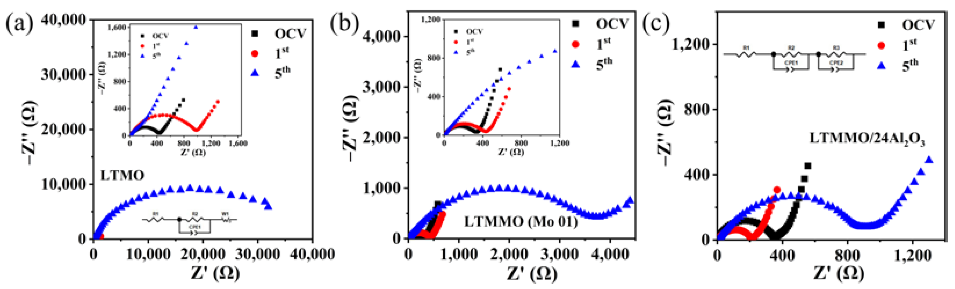
Figure 1. (a) XRD patterns of different LTMMO mixed with KB ball-milled samples; (b) XRD patterns of LTMMO (Mo01) coated with different thicknesses of Al2O3.
Coatings 12 01613 g001
Figure 2. SEM images of the LTMMO materials after ball milling with Ketjen black: (a) Mo00; (b) Mo005; (c) Mo01; (d) Mo015; (e) The distribution of EDS spectra of Mo01 samples; (f) Elemental mapping area; Elemental mapping of Ti (g), Mn (h), Mo (i), and O (j).
Coatings 12 01613 g002
Figure 3. SEM images of Al2O3-coated LTMMO samples with different thicknesses: (a) LTMMO; (b) LTMMO/8Al2O3; (c) LTMMO/24Al2O3; (d) LTMMO/40Al2O3; (e) EDS elemental distribution of LTMMO/24Al2O3 samples with EDS spectra of LTMMO and LTMMO/24Al2O3.; (f) Elemental mapping area; Elemental mapping of Ti (g), Mn (h), Mo (i), Al (j), and O (k).
Coatings 12 01613 g003
Figure 4. Cycling performance of (a) LTMMO materials with different Mo doping, (b) uncoated and Al2O3-coated LTMMO samples.
Coatings 12 01613 g004
Figure 5. HR-TEM images of (a) LTMMO and (b) LTMMO/24Al2O3; 2.15Å corresponds to the interplanar distance of LTMMO (002) face.
Coatings 12 01613 g005
Figure 6. (a) XPS survey spectrum and (bf) core level spectra of transition metals of LTMO, LTMMO (Mo01), and LTMMO/24Al2O3: (b) Ti 2p; (c) Mn 2p; (d) Mo 3d; (e) O 1s; (f) Al 2p.
Coatings 12 01613 g006
Figure 7. (ac) Corresponding charge/discharge curves for 30 cycles of LTMO, LTMMO (Mo01), and LTMMO/24Al2O3, respectively, and (d) cycling performance and coulombic efficiency.
Coatings 12 01613 g007
Figure 8. Cyclic voltammetric curves of (a) LTMO, (b) LTMMO (Mo01), and (c) LTMMO/24Al2O3 electrodes.
Coatings 12 01613 g008
Figure 9. EIS spectra and equivalent circuit diagrams of (a) LTMO, (b) LTMMO (Mo01), and (c) LTMMO/24Al2O3 electrodes.
Coatings 12 01613 g009
Table 1. Fitted impedance parameters of the electrodes.
Samples R2 R3
Battery StateOCV

(Ω)
1st
4.8V
(Ω)
5th
4.8V
(Ω)
OCV

(Ω)
1st
4.8V
(Ω)
5th
4.8V
(Ω)
LTMO423.5963.834547---
LTMO (Mo01)---291.0384.23762
LTMMO/24Al2O3---330.1209.3920.6
Publisher’s Note: MDPI stays neutral with regard to jurisdictional claims in published maps and institutional affiliations.

