Article

A Method for Calculating the Reliability of Welded Metal Bellows for Mechanical Seals

College of Mechanical and Electronic Engineering, Nanjing Forestry University, Nanjing 210037, China
*
Author to whom correspondence should be addressed.
Coatings 2022, 12(2), 175; https://doi.org/10.3390/coatings12020175
Submission received: 13 December 2021 / Revised: 13 January 2022 / Accepted: 26 January 2022 / Published: 29 January 2022
(This article belongs to the Special Issue State-of-the-Art on Coatings Research in Asia)

Abstract

:
Welded metal bellows are an elastic element widely used in the field of mechanical seals. The main objective of the present study was to investigate the reliability of welded metal bellows in mechanical seals under specified working conditions. To this end, a stress relaxation test bench was built to obtain the residual elastic force data of welded metal bellows under different compression loads in high-temperature environments. Then, the elastic force loss equation of the bellows was fitted. Moreover, a failure judgment form of welded metal bellows in the mechanical seal is proposed. According to the calculation relationship between the seal face pressure and the welded metal bellows’ elastic force, the elasticity force loss range of the bellows was 556–708 N. Finally, according to the elastic force loss equation, elastic force loss was determined. The maintenance time of the welded metal bellows, and the bellow’s failure limit state equation were determined, and the limit state equation was substituted into the center point method. The reliability of the welded metal bellows was 0.9958. The results show that the new failure criterion and the center point reliability calculation method proposed in this paper have certain practical value for the rapid reliability prediction of welded metal bellows.

1. Introduction

A mechanical seal is an essential part of rotating machinery, and widely used to seal the fluid leakage from the contact point of the rotating shaft and stationary casing. Mechanical seals have been widely applied in diverse fields, including petroleum, chemical, and aerospace industries [1]. As a critical elastic element, the primary function of the welded metal bellows is to provide the closing force between the rotating part and the stationary end face [2], thereby preserving the seal face pressure within the designed range. When the bellows fail, this will increase the leakage of mechanical seal or aggravate the wear of the seal face, resulting in the seal’s failure [3]. In some chemical enterprises and nuclear energy applications, due to the high temperature of the medium, once the sealing failure occurs, it is easy to cause a major accident [4], so it is of great significance to study the reliability and life prediction of metal bellows.
With the operation of mechanical seals, the elasticity of the bellows gradually decreases [5]. This phenomenon, which mainly originates from stress relaxation, is called elastic force loss, and is significantly more pronounced in high-temperature environments. Studies show that elastic force loss is the main failure reason of welded metal bellows [6]. Accordingly, many investigations have been carried out on the phenomenon of elastic force loss. In this regard, An et al. [7] derived the elastic loss equation of welded metal bellows through performing the stress analysis of welded metal bellows combined with the Bailey–Norton constitutive relation of materials [8]. Then, the elastic force loss of bellows at high temperatures was obtained, and the proposed elastic force loss equation was verified through high-temperature stress relaxation tests. Based on the elastic thin shell theory, strain displacement relationship, and stress relaxation theory, Ma et al. [9] derived mechanical seals with welded metal bellows under actual conditions of the elastic force loss equation. The obtained results through the finite element analysis verified that the elastic thin shell theory could be applied to establish the elastic force loss equation.
Further investigations showed that when the elastic force loss of bellows reaches 18%–20%, the entire bellow’s mechanical seal will leak, resulting in mechanical seal failure [10]. However, this empirical range value has no accurate theoretical basis, and the applicability of the elastic force loss required by the failure of welded metal bellows in mechanical seals under different working conditions remains unclear.
Currently, most investigations in this area focus on the elastic force loss phenomenon of welded metal bellows in mechanical seals at high temperatures. There is not enough data on the reliability of bellows under elastic force loss failure. The existing reliability analysis methods for non-welded metal bellows may provide a reference in this regard. Zeng et al. [11] used ABAQUS finite element software. They studied the performance of EPMB metal bellows and corrugated metal pipes subjected to the limited bending stress distribution in a repeating process. Then, the fatigue failure and the influence of structural parameters on the waveform were analyzed. Cao et al. [12] performed finite element analyses using ANSYS software and calculated the local strain amplitude of U-shaped bellows subjected to failure loads, estimated the bellows’ lives utilizing the correlation between strain and life, and analyzed the reliability of the bellows during their life cycle. According to the stress intensity interference theory, Xie et al. [13] defined the limit state function. They studied the strength reliability of the bellows using the Monte Carlo probability sampling method, considering the statistical randomness of parameters of the metal bellows, including the size, material, and load.
Through the above method of solving the reliability of non-welded metal bellows, it was found that the reliability of bellows nowadays is mostly analyzed from the aspect of fatigue life and structural strength, which requires a large number of data samples. However, in mechanical seals, elastic force loss is the main cause of failure of welded metal bellows. At present, the empirical failure criterion of bellows is the failure of bellows when elastic force loss reaches 18–20%, but this failure criterion is not applicable to mechanical seal bellows under different working conditions. Aiming at the above problems, the failure criterion of bellows under different working conditions is determined by using the relation between the mechanical seal face pressure and the elasticity of the bellows, and the reliability calculation method of center point is used to calculate the reliability of the welded metal bellows in the mechanical seal.
In the present study, a stress relaxation test rig was built to simulate the environment of welded metal bellows of mechanical seals in high-temperature media. The main objective was to obtain residual elastic force data of welded metal bellows under different compression amounts in a high-temperature medium environment, and fit the loss of elastic force equation. Moreover, the relation between the seal face pressure and the elastic force of welded metal bellows was used to determine the range of elastic force loss of welded metal bellows in mechanical seals. Finally, the limit state equation was determined based on the elastic force loss equation, elasticity force loss range, and the welded metal bellows’ maintenance time. The reliability of the welded metal bellows with few samples was calculated using the central point method, and the feasibility of the approach was analyzed.

2. Material and Methods

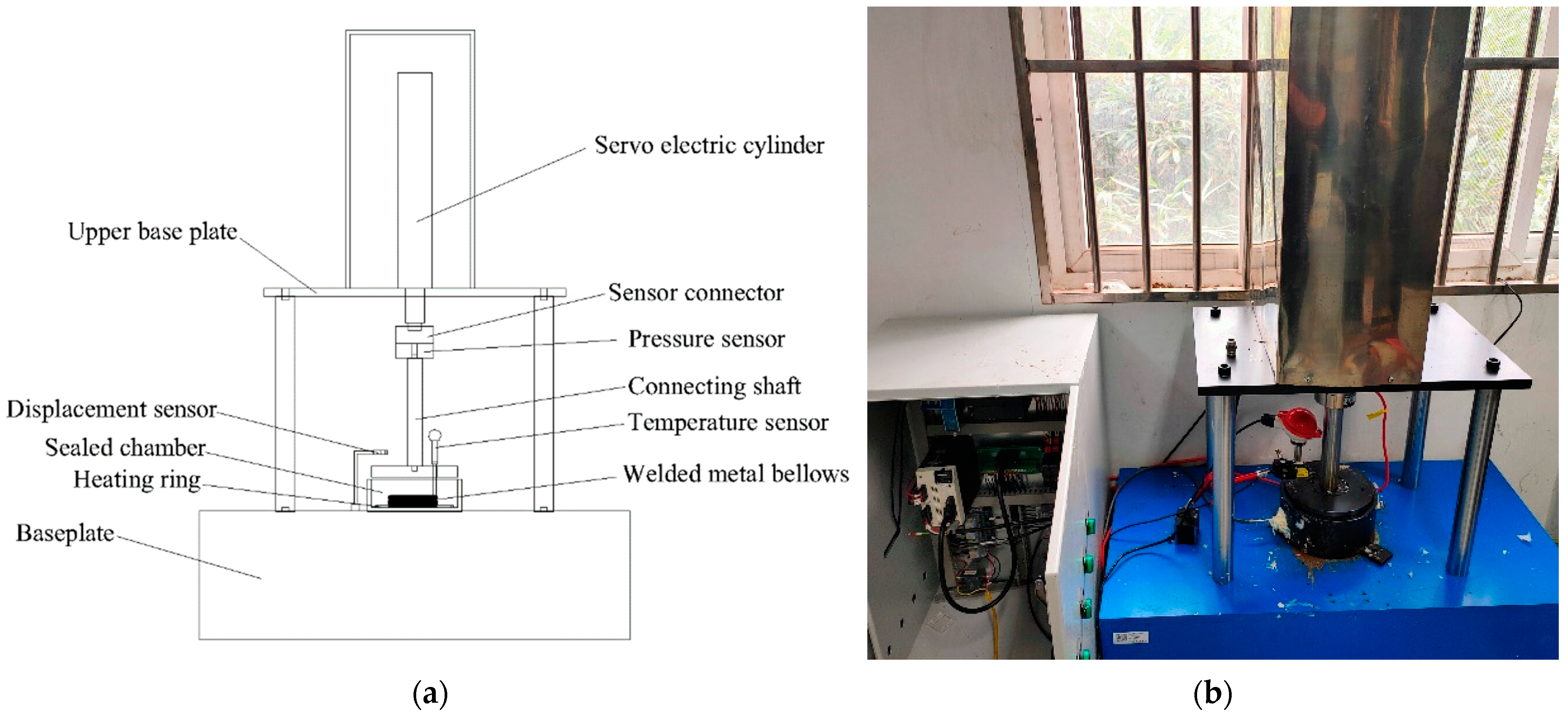
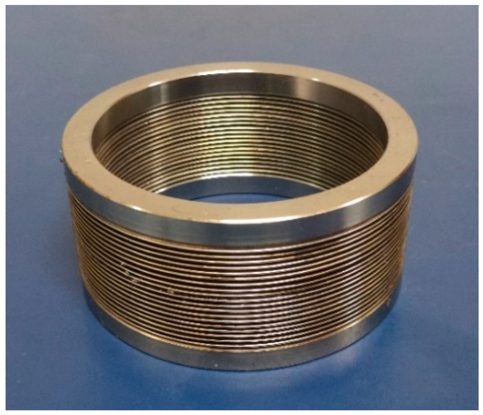
2.1. Stress Relaxation Tests

To test the stress of bellows [14], they are generally placed in a high-temperature box. However, by this method the influence of the medium on the relaxation performance of bellows is not considered. Aiming at resolving the limitations of conventional testbeds, a stress relaxation test system was built to study welded metal bellows [15]. Figure 1a is a schematic diagram test rig. Figure 1b shows the physical diagram of the stress relaxation test rig.
The stress relaxation test was carried out at a high temperature. The test bench had a sealed chamber; equipped with a PID control system to adjust the medium temperature with an accuracy of ±1 °C. The initial displacement load was applied to the welded bellows using a servo-electric cylinder adjustment device. The pressure sensor (Bengbu Gaojing Sensor Company, Bengbu, China) was used to measure the load change during the test, and the displacement change was detected using a displacement sensor (Panasonic, Shanghai, China). Labview programming language compiled the experimental control interface and experimental storage requirements. The test device ensured a constant shrinkage during the test. It had a real-time monitoring function to achieve a continuous dynamic, simple operation, and stability of the test requirements to obtain accurate test data.
The stress relaxation test of welded metal bellows was carried out in a setup test rig to observe the variation of elastic force under different loads in a constant-temperature environment [16]. The bellows were loaded with different displacements based on the stress relaxation theory. During the experiment, the pressure plate and bellows were initially in contact with a pressure sensor value of approximately 10 N, and the medium was preheated. When the test temperature reached a specific value, it was maintained at this temperature for 90 min. It is worth noting that the actual temperature of the bellows should be consistent with the temperature of the test chamber. Finally, the stress relaxation test of the welded metal bellows should be realized by positioning the shift loading. The stress relaxation curves were obtained under different initial displacement loads and load loss curves with time.
According to the literature [7], the elastic force loss equation of welded metal bellows at specified temperature can be written as follows:
F = B t n + P
where F is the residual elastic force, B is the relation of initial pressure, t is time, and P denotes the initial elastic force. Moreover, n is a real constant.
Combined with the experimental data, calculations were performed in the MATLAB environment to fit the relevant data. Accordingly, an expression was established to obtain the elastic force loss of the welded metal bellows.

2.2. Reliability Calculation

2.2.1. Determination of Elastic Force Loss Range of Welded Metal Bellows

Studies have shown that the pressure of the seal face affects the performance of the whole mechanical seal [17]. The seal face pressure can be obtained by balancing the axial forces [18]. Figure 2 shows the schematic configuration of the rotating ring and the imposed loads in a mechanical seal, where D 1 and D 2 are the inner and outer diameters of the seal ring contact face, respectively. Moreover, d 0 is the axle diameter, and P a   and   P b denote the applied pressure on bellows and medium pressure.
Pressing force:
F a = P a × π 4 ( D 2 2 D 1 2 )
F b = P b × π 4 ( D 2 2 d 0 2 )
push force:
R = λ P b × π 4 ( D 2 2 D 1 2 )
where F a is the elastic force of bellows, F b is medium force, R is the liquid film push force, and λ is a real constant, λ = R ( A × P × b ) [19].
Since friction on the auxiliary sealing ring is very small, it is generally ignored in the calculations. Accordingly, the resultant force on the rotating ring is F = F a + F b R . Meanwhile, the seal face pressure P C can be expressed in the form below:
P c = F A = F a + F b R π 4 ( D 2 2 D 1 2 )
Reduction:
P c = P a + P b ( D 2 2 d 0 2 D 2 2 D 1 2 λ )
Equation (6) indicates that when the medium pressure is constant, Pa determines the pressure on the seal face. When Pa falls in a reasonable range, it can provide the required closing force of the end face so that the mechanical seal does not fail. On the other hand, the mechanical seal fails when Pa is beyond the reasonable limit. The initial elastic force range of the welded metal bellows can be calculated according to the working and structural parameters of mechanical seals and Equation (6).

2.2.2. Reliability Calculation Based on the Central Point Method

Freudenthal [20] proposed an innovative method to calculate reliability using the central point method. Since then, this method, which requires few samples and has a simple calculation, has been widely applied to calculate the structural reliability of mechanical seals [21]. Accordingly, this method was used in the present study to estimate the reliability of welded metal bellows. The calculation process of the central point method is as follows [22].
Firstly, it is assumed that the initial elastic force of welded metal bellows is P. Since the initial elastic force of the bellows is applied artificially, P has certain randomness. Assume that the service time of bellows is t, and manual detection is required at time t. If the elastic force of the bellows can no longer support the seal face pressure, the bellows should be replaced. Moreover, the detection time t has certain randomness. Since the error caused by the operator has uncertainties, the two random variables, P and t are assumed to follow the normal distribution to simplify the calculations. In all analyses, expectation and standard deviation of P and t are marked μ P ,   μ t , and σ P ,   σ t , respectively.
Assume that the elastic force function of bellows is:
Z = g ( P , t ) .
In this case, the corresponding limit state equation can be expressed as follows:
Z = g ( P , t ) = 0 .
Performing the Taylor series expansion at mean point ( μ P ,   μ t ) and retaining the linear terms results in the following expression:
Z g ( μ P , μ t ) + g P g P | μ P ( P μ P ) + g t | μ t ( t μ t ) .
After linearization, the limit state equation can be rewritten in the form below:
Z g ( μ P , μ t ) + g P | μ P ( P μ P ) + g t | μ t ( t μ t ) = 0 .
The reliability index is expressed as:
β = μ Z σ Z = Z ( μ P , μ t ) [ ( Z P | μ x σ P ) 2 + ( Z t | μ x σ t ) 2 ] 1 2
Then, the reliability probability P f and failure probability P r can be expressed as:
P f =   ( β )
P r = 1 P f
where ∅ is the standard normal distribution function.

3. Results and Discussion

This section is intended to calculate the reliability of 316 L welded metal bellows in a mechanical seal (Burgmann BGMFL85, Dandong, China). The total length of the bellows, the wall thickness, and the slice thickness were 35, 8.4, and 0.15 mm, respectively. Moreover, the outer and inner diameters were 114.3 and 97.6 mm, respectively. The wavenumber was 18, and the working environment was set to 250 °C. A bellow sample is shown in Figure 3. During the test, the bellows were subjected to a constant displacement; the test was carried out for 16 h. The measured initial elastic force under four different compression amounts is shown in Figure 4. Furthermore, the change of elastic force with loading time is shown in Figure 5.
Stress relaxation characteristics of welded metal bellows under different initial displacement loading conditions were tested on a test bench, the characteristic of Figure 5 illustrates that the stress relaxation had two stages: in the first stage, relaxation rate was faster, with a shorter duration; as time continued, there was slack in the second stage, a stage of relaxation rate slowdown from the first stage, where the duration was longer than the first stage. The load loss was the difference between the current value of the spring force and the initial spring force, denoted as ∆P. Figure 6 shows the variation relation of load loss quantity ∆P over time under different initial displacement loads. The change trend of load loss in Figure 6 can also verify the change of relaxation stage, and the stress relaxation failure degree becomes more and more obvious with the increase in initial displacement load. The load loss increased with time, but the increasing trend gradually decreased. It can also be seen from Figure 5 that the load loss rate of welded metal bellows increased with the increase in the initial displacement load in the test, as shown in Figure 7. Figure 7 reflects this relationship well. The load loss rate had an almost linear relationship with the increase in initial displacement load. The solid line is the actual point of load loss rate, and the dotted line is the trend line of the solid line. When the initial displacement load was 12 mm, the load loss rate was about 3%, and with the increase in the initial load, the load loss rate was 3.8%, 4.9% and 5.3%, respectively. According to the above rules referring to relevant data and test data [23], it can be concluded that the bellows’ elastic force loss data obtained by using the stress relaxation test bench of welded metal bellows in this paper were in accordance with the rules, and the test data can be used.
According to the stress relaxation test data under the different initial displacement loads above, the curve fitting toolbox in MATLAB software was used to fit Equation (1). The fitting results are shown in Table 1.
It can be seen from Table 1 that the value of n was concentrated around 0.06. To simplify the subsequent calculation, n = 0.06 is taken in this paper. Different initial loads correspond to a b value, and the b value is only related to the initial elastic force P-value. The curve fitting toolbox was used to fit the relationship between the B and P values. The B value is:
B = 27.14 e ( P 650.7 248 ) 2 .
Moreover, the residual elastic force equation of the welded metal bellows at 250 celsius is:
F = 27.14 e ( P 650.7 248 ) 2 × t 0.06 + P .
Applying 10 mm constant compression displacement to the welded metal bellows, the diagram of residual elastic force under 10 mm compression was obtained. The initial elastic force of 10 mm compression was substituted into Equation (15) to obtain the corresponding curve of the actual predicted value and the real measured and controlled value, as shown in Figure 8.
Comparing the fitted and measured values revealed that the calculated values agreed with the experiment. The theoretical formula reflected the elastic force loss of the welded metal bellows at high temperatures.
In the performed analyses, the pressure of the mechanical seal face varied from 0.54 to 0.6 MPa, and the selected medium pressure was 0.4 MPa [24]. The inner and outer diameters of the contact end face of the sealing ring were 100 and 115 mm, respectively, and the diameter of the shaft (sleeve) was 95 mm. It is worth noting that when the axle diameter varies in the range 50–150 mm, λ is usually set to 0.5 to reduce the calculation error. Accordingly, λ was set to 0.5 in all the calculations. According to the correlation between the seal face pressure and the elastic force of the bellows, and various parameters of the mechanical seal, the initial elastic force value range P of the welded metal bellows varied in the range 556–708 N. When the elastic force of welded metal bellows in the mechanical seal w less than 556 N, mechanical seal face pressure is not within a reasonable range, which may result in failure.
According to the requirements of the seal face pressure, the initial elastic force of welded metal bellows during the installation is μ P = 650 N, σ P = 17.3494, the test service time [25] is μ t = 20,000 h, σ t = 60.5530, and the minimum elastic force is 556 N.
The limit state equation of welded metal bellows can be expressed in the form below:
Z = 27.14 e ( P 650.7 248 ) 2 × t 0.06 + P 556 .
The limit state equation is:
Z = 27.14 e ( P 650.7 248 ) 2 × t 0.06 + P 556 = 0
because:
Z P | μ x = 27.14 e ( μ P 650.7 248 ) 2 μ t 0.06 μ P 650.7 30752 + 1 = 0.9989
Z t | μ x = 1.6284 e ( μ P 650.7 248 ) 2 μ t 0.94 = 0.0001475 .
Based on Equation (10), the linearized limit equation is:
Z = 0.9989 P + 0.0001475 t 601.5014 .
Welded metal bellows reliability index β is:
β = μ Z σ Z = Z ( μ P , μ t ) [ ( Z P | μ x σ P ) 2 + ( Z t | μ x σ t ) 2 ] 1 2 .
Subsequently, the reliability of the studied welded metal bellows was β = 2.59. According to the standard normal and normal distribution function table, the reliability of welded metal bellows can be calculated as follows:
P f = ( β ) = 0.9952 .
The failure probability of welded metal bellows in mechanical seals is:
P r = 1 P f = 0.0048 .
Equation (23) indicates that the failure probability of the welded metal bellows after 20,000 h is 0.48%, which is acceptable for the general-purpose mechanical sealing systems.
In this paper, the reliability of welded metal bellows was 0.9952 by using the central point method. Zhou Jian fen [26] used Monte Carlo method to solve the reliability of various parts in the mechanical seal, among which the reliability of elastic elements in the mechanical seal was 0.99. The results can prove the accuracy of the data in this paper to a certain extent, and meet the mechanical seal system requirements. The reliability obtained in this paper is acceptable for general mechanical sealing systems.
The actual working process of the mechanical seal is not suitable for the fixed elastic force loss, due to the failure criterion of the welded metal bellows. According to the actual working conditions of the mechanical seal, the elastic force loss range of bellows that meets the seal face pressure should be solved, so as to accurately solve the reliability of bellows. Compared with other reliability solving methods (Monte Carlo, Six Sigma, etc.), the center point method requires fewer sample data and has a faster solving speed, which is suitable for rapid estimation of the reliability of welded metal bellows in mechanical seal systems.

4. Conclusions

In this paper, the elastic force loss range of welded metal bellows was solved according to the mechanical seal condition, and the reliability of the bellows was solved according to the central point method. The conclusions were as follows:
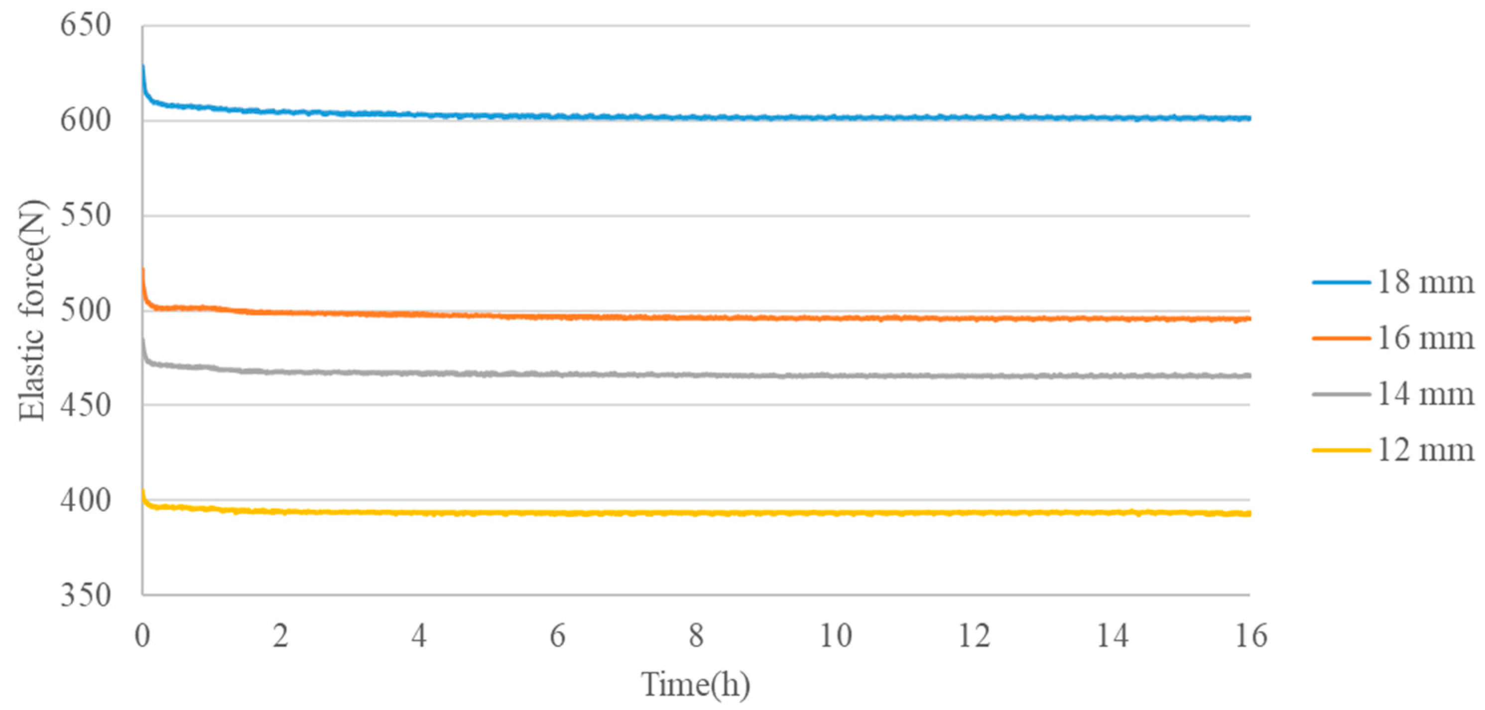
  • The stress relaxation degree of welded metal bellows becomes more significant with the increase in initial displacement load. Based on the stress relaxation test data, the equation of bellows loss is obtained.
  • According to the relationship between the seal face pressure of mechanical seal and the axial elasticity of welded metal bellows, it can analyze the elastic force loss range of welded metal bellows under different working conditions.
  • The reliability of welded metal bellows under specific working conditions can be obtained quickly by using the central point method, and the results have certain reliability.

Author Contributions

Conceptualization, Z.Z. and C.M.; methodology, Y.Z. and J.S.; formal analysis, Z.Z. and X.N.; software, Z.Z. and C.M.; writing—original draft, Z.Z., C.M. and Y.Z.; writing—review and editing, Y.Z. and J.S. All authors have read and agreed to the published version of the manuscript.

Funding

This work was supported by the National Key R&D Program of China (Grant No. 2018YFB2000800) and The National Natural Science Foundation of China (Grant No. 52075268).

Institutional Review Board Statement

Not applicable.

Informed Consent Statement

Not applicable.

Data Availability Statement

Data sharing is not applicable to this article.

Conflicts of Interest

The authors declare no conflict of interest.

Nomenclature

FResidual elastic force
ttime
PInitial elastic force
D1Inner diameter of seal ring contact face
D2outer diameter of seal ring contact face
d0axle diameter
Papressure on bellows
Pbmedium pressure
λconstant
ZFunction function
βReliability index
PfReliability probability
PrEffective probability
ΔPLoad loss

References

  1. Fei, M. Discussion on the mechanical seal of external moving ring. J. Manag. Technol. SME 2017, 04, 177–178. [Google Scholar]
  2. Plumridge, J.M.; Ketch, D.P.; Straszewski, C.J. Mechanical seals: The current status of metal bellows sealing. Tribol. Int. 1986, 19, 193–197. [Google Scholar] [CrossRef]
  3. Tian, X.F. Comparative Analysis of Dynamic characteristics and Fatigue Characteristics of Metal Bellows in Mechanical Seals. Master’s Thesis, Xinjiang University, Urumqi, China, 2018. [Google Scholar]
  4. Zhou, C. Theoretical Calculation and Experimental Study on Stiffness and Fatigue Life of Bellows in Automobile Exhaust System. Master’s Thesis, Nanjing University of Science and Technology, Nanjing, China, 2018. [Google Scholar]
  5. Yang, W.J.; Hao, M.M.; Ren, B.J.; Wang, X.Y. Analysis of the Elastic-Loss Feature of welded Metal Bellows for High Temperature Mechanical Seals. J. Lanzhou Univ. Technol. 2016, 4, 46–50. [Google Scholar]
  6. Wen, Y.Z.; Xue, F.T.; Tian, X.F. Structural and thermal coupling failure analysis of mechanical seal bellows under extreme conditions. Fluid Mach. 2018, 46, 5. [Google Scholar]
  7. An, Y.S.; Cai, R.L.; Liu, W.D. Study on the mechanism of elastic loss of welded metal bellows: Stress force relaxation. Lubr. Seal. 2002, 1, 7–9. [Google Scholar]
  8. Kraus, H. Creep Analysis; John Wiley & Sons: Hoboken, NJ, USA, 1980. [Google Scholar]
  9. Ma, Y.M. Study on mechanism of projectile loss of welded metal bellows based on thin shell theory. Petrochem. Equip. 2020, 19, 17–22. [Google Scholar]
  10. Li, X.; Yang, B.F.; Zheng, G.Y.; Dai, X.W. Failure analysis of metal bellows mechanical seal for high temperature heavy oil pump. Chem. Mach. 2011, 3, 367–369. [Google Scholar]
  11. Hao, Z.L.; Luo, J.T.; Chen, L.H.; Cai, Y.; Chen, Y.H.; Cheng, M.Z. Failure mechanism of unequal parameters metal bellows under repeated bending process. Eng. Fail. Anal. 2021, 129, 105671. [Google Scholar] [CrossRef]
  12. Cao, W.H.; Yu, X.C. Fatigue life reliability analysis of bellows. Chem. Autom. Instrum. 2010, 37, 56–58. [Google Scholar]
  13. Xie, J.; Chen, Y.L.; Chen, H.J. Probabilistic finite element analysis of structural reliability of metal bellows. Chem. Eng. Equip. 2019, 271, 210–212. [Google Scholar]
  14. Wang, K. Analysis of Stress Relaxation Characteristics and Service Life Prediction of Spiral Compression Spring. Master’s Thesis, Xi’an University of Technology, Xi’an, China, 2019. [Google Scholar]
  15. Ding, W.; Ma, Y.M.; Sun, S. Development of the test device for elasticity loss of the welded metal bellows in mechanical seal. Mach. Des. Manuf. Eng. 2016, 45, 63–66. [Google Scholar]
  16. Chen, W.; Wang, X.; Yan, Y.; Sumigawac, T.; Kitamura, T.; Feng, M.; Xuan, F. Bending stress relaxation of microscale single-crystal copper at room temperature: An in situ SEM study. Eur. J. Mech. -A/Solids 2021, 90, 104377. [Google Scholar] [CrossRef]
  17. Tang, Y. Analysis of influencing factors of mechanical seal failure. Sci. Technol. Vis. 11 2017, 283, 71. [Google Scholar]
  18. Zhang, B.R. Cause analysis and improvement of mechanical seal failure of alkali pump. China Equip. Eng. 2021, S2, 114–115. [Google Scholar]
  19. Zou, X.H.; Wang, J. Analysis of factors affecting performance of mechanical seal’s end-face characteristics. Top. Chem. Mater. Eng. 2018, 1, 233–235. [Google Scholar]
  20. Freudenthal, A.M. The safety of structures. J. Trans. Am. Soc. Civ. Eng. 1947, 112, 125–159. [Google Scholar] [CrossRef]
  21. Wu, Z.Y.; Shi, Q.; Guo, Q.Q.; Chen, J.K. Cst-based first order second moment method for probabilistic slope stability analysis. Comput. Geotech. 2017, 85, 51–58. [Google Scholar] [CrossRef]
  22. Li, J.; Guo, Z.P.; Guo, J.X. Reliability analysis of bolt support in underground roadway based on central point method. Coal Mine Saf. 2019, 50, 243–246, 250. [Google Scholar]
  23. Yin, X.Y. Effect of Temperature and Stress Acceleration Test on Stress Relaxation Behavior of Spiral Compression Spring. Master’s Thesis, Tianjin University, Tianjin, China, 2012. [Google Scholar]
  24. GB/T 33509-2017General Specifications for Mechanical Seals, Standardization Administration of the P.R.C: Beijing, China, 2017.
  25. API 682-2002Pump—Shaft Seal Systems for Centrifugal Pumps and Rotary Pumps Technical Specifications, American Petroleum Institute: Washington, DC, USA, 2014.
  26. Zhou, J.F.; Gu, B.Q. Reliability evaluation method of mechanical seals based on monte carlo method. Lubr. Eng. 2006, 2, 102–104, 135. [Google Scholar]
Figure 1. (a) Schematic diagram of stress relaxation test rig. (b) Physical drawing of stress relaxation test rig.
Coatings 12 00175 g001
Figure 2. Stress distributions on the rotating ring in a balanced sealing system.
Coatings 12 00175 g002
Figure 3. Bellow sample drawing.
Coatings 12 00175 g003
Figure 4. Distribution of compression—elastic force.
Coatings 12 00175 g004
Figure 5. Elastic force relaxation curves under different compressions.
Coatings 12 00175 g005
Figure 6. Distribution of load loss with time under different initial loads.
Coatings 12 00175 g006
Figure 7. Corresponding diagram of compression and load loss rate.
Coatings 12 00175 g007
Figure 8. Distribution of elastic force-fitting and test values.
Coatings 12 00175 g008
Table 1. Values of B and N corresponding to different elastic forces.
Initial Elastic Force405.5484.9521.8632.5
B−10.33−16.51−22.05−26.71
n0.0650.0580.0590.061
Publisher’s Note: MDPI stays neutral with regard to jurisdictional claims in published maps and institutional affiliations.

