Abstract
This paper reports a method for fabricating pie-shaped CoMoO4 nanomaterials. The morphologic characterization and phase analysis showed that the prepared material was CoMoO4 and presented a pie-shape. Pie-shaped CoMoO4 electrode materials possess high specific capacitance in three-electrode electrochemical measurement systems. When the current density is 1 A/g, the specific capacitance reaches 1902 F/g. In addition, it has good cycle stability. With 10,000 charge–discharge cycle experiments at a current density of 15 A/g, pie-shaped CoMoO4 has a specific capacity retention ratio of 99.5%. In addition, the CoMoO4//CNTs device can provide a maximum energy density of 55.6 Wh/kg (1 A/g) and a maximum power density of 10,900 W/kg (15 A/g), showing good electrochemical performance. The photocatalytic properties of pie-shaped CoMoO4 were also studied. The results show that the degradation rates of MO (methyl orange), MB (methyl blue), and CR (Congo red) can reach 97.8%, 98.8%, and 99.6% at 100 min, 40 min, and 65 min, respectively. The material has good photocatalytic performance. The excellent performance of pie-shaped CoMoO4 indicates that the electrode material has potential application scenarios in electrode materials and photocatalysis.
1. Introduction
The global demand for the energy crisis and clean energy is getting higher and higher. Energy shortage and environmental pollution are serious problems at present [,]. Batteries are currently the main form of energy storage. Traditional batteries pollute the environment and do not last long. Supercapacitors are a new type of high-energy energy storage device [,,,], and are widely used in backup power supply, new energy vehicles, and other fields. With the characteristics of high power density and high specific capacitance, it has become a promising energy storage method. Because of this, many countries have spared no effort in the research and development of supercapacitors [].
Metal oxide is a popular electrode material for supercapacitors that has been widely studied. The molybdate crystal structure is stable and has strong REDOX ability, which has attracted extensive attention in the field of energy storage. Among many molybdates, CoMoO4 has rich REDOX states, simple synthesis, low cost, good conductivity, fast speed, and other advantages [,]. It also has an exceptionally excellent specific capacity and forbidden bandwidth. In addition, the surface morphology affects the specific surface area and the ion diffusion distance of the material []. The pie-like structure, with a relatively large specific surface area and more surface active sites, can effectively improve the electrochemical and photocatalytic properties of the material. Therefore, the preparation of nanoscale CoMoO4 materials has used both electrode and photocatalytic materials. Xue-wei Dong et al. [] successfully prepared NiCo2O4@CoMoO4 nano-3D self-supported layered structure material, which has good electrochemical performance. At a scanning rate of 5 mV/s, the specific capacitance is 1543.14 F/g, and the current density of 5 mV/s is continuously charged and discharged 1000 times. The cycle efficiency was up to 95.0%. Zhang Peng et al. [] synthesized NiMoO4/CoMoO4 nanorods through hydrothermal reaction and subsequent calcination, which showed a high specific capacitance of 1164 F/g at 2 A/g and maintained a capacitance of 75% after 3000 cycles at 10 A/g. CoMoO4 has also attracted extensive research interest in its photocatalytic performance. Ma Tian et al. [] synthesized Fe-g-C3N4 and CoMoO4 into unique composite materials through a simple hydrothermal pathway and high-temperature calcination, and their study showed that the degradation efficiency of this material for MB was up to 99.5%. Irum Shaheen et al. [] synthesized ZnO/CoMoO4 nanocomposite, and the results showed that the efficiency of the material in reducing MO under light and dark conditions reached 99% and 96%, respectively. The above data provide reliable data support for the study of electrochemical and photocatalytic properties of CoMoO4 electrode material, which has great research potential.
In this paper, pie-shaped CoMoO4 nanomaterials were fabricated. The specific capacity of the product can reach 1902 F/g when the current density is 1 A/g. After 10,000 cycles, the specific capacity retention rate is 99.5%. The composite material shows good capacitance performance. CoMoO4//CNTs devices can provide high energy density and power density, and also have good cycle stability. The degradation efficiency of MO, MB, and CR reached 97.8%, 98.8%, and 99.6%, respectively, showing excellent photocatalytic performance.
2. Experiment
2.1. Synthesis of Pie-Shaped CoMoO4 Nanoparticles
Under normal temperature and pressure, 10 mmol Co(NO3)2·6H2O was dissolved in 50 mL dilute nitric acid (45 mL deionized water + 5 mL concentrated nitric acid). Then, 10 mmol citric acid was added to the mixture and heated to 80 °C by a magnetic stirrer until it was evenly mixed, and denoted as solution A. Then, 1.45 mmol (NH4)6Mo7O24·4H2O was dissolved in 50 mL of deionized water, and20 mmol citric acid was added to the mixture, before being stirred by a magnetic stirrer until the mixture was evenly recorded as the B solution. In the state of the magnetic stirrer, first of all, B solution was slowly added to A solution, until they were evenly mixed, and then the pH was adjusted to between 5 and 7 with ammonia. Then, continue to heat and stir until the solution until it becomes a thick gel. Secondly, the gel was poured into a crucible and then dried in an oven at 80 °C for 6 h. Finally, the obtained precursor was put into the Muffle furnace, and the Muffle furnace was heated from room temperature to 450 °C and kept for 5 h to obtain the pie-shaped CoMoO4.
2.2. Preparation of CNTs
A total of 1.5 g of carbon nanotubes were mixed with 300 mL of 70% hydrochloric acid, and then treated at 70 °C for 10 h. Then, the carbon nanotubes were washed with deionized water and dried at 40 °C for 4 h. The preparation process of the negative electrode of the supercapacitor is as follows: firstly, carbon nanotubes (75 wt%) were mixed with carbon black (15 wt%) and polyvinylidene fluoride (PVDF, 10 wt%). Then, a small amount of N-methylpyrrolidone (NMP) was added to form a uniform mixture. The resulting mixture was coated on 1 cm2 of Ni foam and dried at 75 °C for 8 h.
2.3. Materials Characterization
Scanning electron microscopy (SEM, FEI, Hillsboro, OR, USA, Quanta 450) and transmission electron microscopy (TEM, JEOL, Tokyo, Japan, JEM-2010) were used to characterize the microstructure of the prepared materials. Magnification SEM multiples can clearly see the material’s microstructure. TEM can be used for morphology observation, selective electron diffraction and energy spectrum analysis, and is widely used in the morphology and composition analysis of inorganic, organic, and biological materials. Using X-ray diffraction (XRD, D8 Advance, Bruker, Billerica, MA, USA, with Cu target K alpha radiation source, A = 0.15406 nm) for CoMoO4 nano material phase structure analysis, XRD analysis is a kind of X-ray diffraction method in crystal material, which then determines the phase composition and crystal structure of the material which was characterized one way.
2.4. Performance Testing
The three-electrode system was used for electrochemical testing. The three-electrode device used the sample electrode as the working electrode, the platinum sheet and calomel electrode as the counter electrode and the reference electrode, respectively, and the 2 mol/L KOH solution as the electrolyte. The cyclic voltammetry (CV) curve, constant current charge–discharge (GCD) curve and electrochemical impedance spectroscopy (EIS) of the samples were tested by Shanghai Chenhua (Shanghai, China) CHI760C electrochemical workstation. The scanning rate of the CV curve ranges from 5 to 120 mV/s, and the tested voltage window is −0.2–0.6 V. The current density of the GCD curve ranges from 1 to 15 A/g. The amplitude of the disturbance was 5 mV and the frequency range was 0.01 Hz–100 kHz.
2.5. Electrochemical Performance Test
The three-electrode system was used for electrochemical testing. The three-electrode device used the sample electrode as the working electrode, the platinum sheet and calomel electrode as the counter electrode and the reference electrode, and 2 mol/L KOH solution as the electrolyte. The CV curve, GCD curve and EIS of the samples were tested by Shanghai Chenhua CHI760C electrochemical workstation. The scanning rate of the CV curve ranges from 5 to 120 mV/s, and the tested voltage window is −0.2–0.6 V. The current density of the GCD curve ranges from 1 to 15 A/g. The amplitude of the disturbance was 5 mV and the frequency range was 0.01 Hz–100 kHz.
The samples were analyzed with a UV–visible spectrophotometer (Lambda 950, Perkin Elmer, Waltham, MA, USA) with a scanning wavelength range of 250–800 nm to evaluate the photocatalytic performance of the samples.
The specific capacity, energy density, and power density of the material after testing were calculated using the following Equations (1)–(5) []:
Cs = I Δt/m ΔV
E = 0.5 Cs ΔV2/3.6
P = 3600 E/Δt
q = Cs × ΔV × m
m+/m− = C− × ΔV−/C+ × ΔV+
Cs (specific capacity, F/g), i (current density, A), Δt (discharge time, s), ΔV (voltage drop, V), m (mass of active substance, g), E (energy density, Wh/kg), P (power density, W/kg).
3. Results and Discussion
The microstructure of the material was analyzed by SEM and TEM, as shown in Figure 1a,b. As can be seen in Figure 1a, a large number of CoMoO4 nanoparticles were successfully attached to the nickel foam conducting substrate, stacking on top of each other. Figure 1b shows the high-power SEM photo, which clearly shows that the prepared products have a pie structure with a uniform particle size and a size of approximately 100 nm. They are stacked together to form non-uniform pores, which are conducive to increasing the specific surface area of the material. We continue to conduct SEM mapping tests for this material, as shown in Figure 1c–f. It can be seen that the three elements Mo, Co, and O are uniformly distributed, and the resulting products do not contain other impurities.
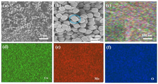
Figure 1.
(a,b) SEM images of CoMoO4 pie nanoparticles at different magnifications. (c) SEM mapping images of CoMoO4. (d–f) SEM mapping images of Co, MO, and O elements, respectively.
In order to more clearly observe the morphological characteristics of the products, we performed TEM tests on the material, as shown in Figure 2a. The pie-shaped CoMoO4 nanomaterial is approximately 100 nm-long and 200 nm-wide, and we continued with the HRTEM test as shown in Figure 2b. The lattice spacing of 0.33 nm can be seen in the figure and is located in the (002) lattice of the CoMoO4 electrode material. The inset in the figure shows the SEAD test plot, which indicates that the synthesized product CoMoO4 is a polycrystalline material. Figure 2c shows an EDS test of the material, which shows that the CoMoO4 electrode material contains three elements, namely O, Co, and Mo, which is consistent with the SEM mapping test. We further performed XRD tests on the synthesized material, as shown in Figure 2d. Figure 2e shows the specific surface area test of the cake CoMoO4. The results show that the prepared material ratio shows that the area is up to 131.2 m2/g. This is in agreement with the results of the standard card (PDF card, no. 25-1434). The above analysis shows that the pie-shaped CoMoO4 nanomaterials were successfully synthesized.
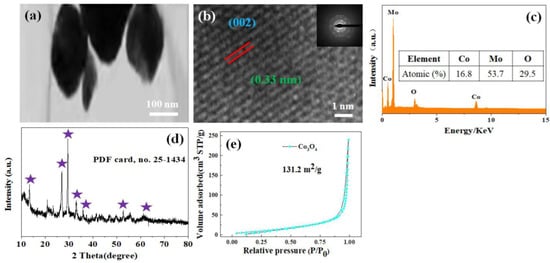
Figure 2.
(a) TEM image of the hybrid CoMoO4 pie nanoparticles. (b) HRTEM image of the as-prepared CoMoO4 nanoparticles and the inset is the corresponding SAED pattern. (c) The EDS spectrum of CoMoO4 nanoparticles. (d) XRD pattern of CoMoO4 nanoparticles. (e) Nitrogen adsorption–desorption isothermal curve.
In order to further study the electrochemical performance of pie-shaped CoMoO4, we tested the CV curves of CoMoO4 at different scan rates, as shown in Figure 3a. As can be seen from the figure, there is a pair of obvious REDOX peaks in the CV curve, which shows the strong pseudocapacitance characteristics of the material. The Faraday reaction corresponding to the REDOX peak is as follows []:
3[Co(OH)3]− ↔ Co3O4 + 4H2O + OH− + 2e−
Co3O4 + H2O + OH− ↔ 3CoOOH + e−
Co3O4 + H2O + OH− ↔ 3CoOOH + e−
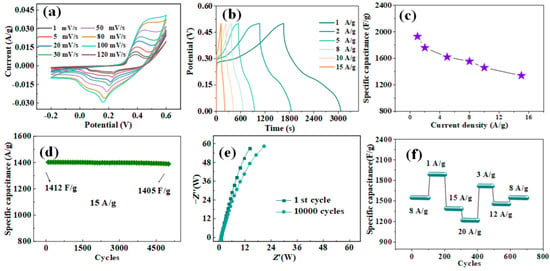
Figure 3.
(a) CV curves of CoMoO4 nanoparticles at different scan rates. (b) Charge–discharge curves of CoMoO4 nanoparticles at different current densities. (c) Specific capacitance of CoMoO4 nanoparticles at varied current densities. (d) The cycling performance of pie-shaped CoMoO4 at the current density of 15 A/g. (e) Nyquist plot of CoMoO4 nanoparticles. (f) Rate and cycle stability tests under different current densities.
Mo atoms are not involved in the whole REDOX process, so the REDOX characteristics of Mo atoms will not affect the measured capacitance []. The area enclosed by the CV curve of the CoMoO4 electrode increases with the increase in sweep speed. This indicates that more energy was stored, but the shape did not change significantly, indicating that the pie-shaped CoMoO4 had good stability. Figure 3b shows the charge and discharge curves of the constant current under different current densities. The charge–discharge curve has good symmetry, showing good electrochemical reversibility and charge–discharge performance. When the current density is 1, 2, 5, 8, 10, and 15 A/g, the corresponding specific capacitance can be calculated using Equation (1), as shown in Figure 3c. Pie-shaped CoMoO4 showed high specific volumes of 1902, 1720, 1615, 1523, and 1412 F/g, respectively. Cyclic stability tests for pie-shaped CoMoO4 are shown in Figure 3d. After 10,000 cycles at a current density of 15 A/g, the specific capacitance of the pie-shaped CoMoO4 changed from 1412 to 1405 F/g, with a capacitance retention of 99.5%. This demonstrates the high specific capacitance and excellent cycling stability of the pie-shaped CoMoO4 [,]. Figure 3e shows the Nyquist plots of pie-shaped CoMoO4 after the 1st and 10,000th cycles. As can be seen from the figure, there is not much difference in arc increment in the high-frequency region. In the low-frequency region, the slope of the curve decreases slightly. This indicates a slight increase in the diffusion resistance of the material, which may be due to the corrosion of the nanostructures by dissolved oxygen in the electrolyte during the charging and discharging cycle, leading to the loss of adhesion of some of the deposited active substances. Figure 3f shows that the specific capacitance is stable for the first 100 cycles with an A current density of 8 A/g. After continuously changing the current density and then returning to the initial current of 8 A/g, the specific capacitance remains stable and the specific capacitance loss is very small. This indicated that the pie-shaped CoMoO4 electrode had excellent cycling stability. The products prepared by us were compared with those in the literature, as shown in Table 1. The results show that the material has good electrochemical performance.

Table 1.
Comparison of properties of electrode materials with references.
CNTs have become one of the most widely used electrode materials for supercapacitors due to their low price and excellent electrochemical performance [,]. Figure 4 shows the constant current charge–discharge test of CNTs at 1, 3, 5, 8, 10, and 15 A/g current densities. According to the specific capacity equation, we calculated the specific capacity at different current densities, which were 283, 266, 251, 242, 235, and 226 F/g, respectively. The charging and discharging curves of CNTs are approximately triangular symmetric, which further indicates that the CNTs electrodes have good reversibility of charging and discharging.
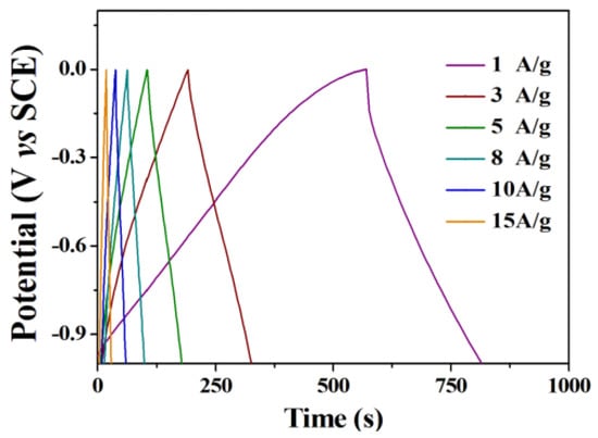
Figure 4.
Charge–discharge curves of the CNTs electrode at different current densities.
The experimentally prepared CoMoO4 and CNTs were assembled into asymmetric supercapacitors, as shown in Figure 5. Before assembly, the optimum mass ratio between positive and negative electrode materials is calculated. According to the specific capacity of positive and negative electrode material at 1 A/g is 1902 F/g and 283 F/g, the voltage drop is 0.5 and 1 V, respectively. According to the best mass matching Equation (5), the mass ratio of the best positive and negative electrode material is m+/m− ≈ 3/10.

Figure 5.
The schematic mechanism of the supercapacitors device.
In order to verify the performance of the fabricated device, a cyclic voltammetry test was carried out on the device, as shown in Figure 6a. The CNTs and CoMoO4 potential window −1~0 V and −0.3, respectively, ~0.6 V, explain the theory that the device can achieve a 1.6 V voltage window. Figure 6b shows the CV curve test of the CoMoO4//CNTs electrode at different sweeping speeds. With the increase in scanning speed, the CV curve increases proportionally, and the peak current increases linearly with the increase in scanning speed. This shows that the material has good kinetic properties. Figure 6c shows the constant-current charge–discharge curve of the device under different current densities. It can be seen from the figure that the charge–discharge curve is close to a triangle with good symmetry. This shows that the material has a good rate of performance []. According to Equation (1), we calculated the specific capacity under different current densities, as shown in Figure 6d. The specific capacitors of the device at current densities of 1, 2, 5, 8, 10, and 15 A/g are 118, 106, 95, 86, 76, and 68 F/g, respectively. Figure 6e shows the cyclic stability test of CoMoO4//CNTs devices. After 10,000 cycles, the specific capacitance of the electrode of the CoMoO4//CNTs device changed from 106 to 103 F/g, maintaining a capacitance retention of 97.2%. This indicates that CoMoO4//CNT devices have excellent cycle stability. We compare our work with other energy storage elements, as shown in Figure 6f. According to Equations (2) and (3), we calculate the energy density and power density of the device. When the current density is 1 A/g, the power density reaches 10,900 W/kg, and the energy density is 55.6 Wh/kg. By comparing with the devices in the literature, the assembled devices have good energy storage characteristics.
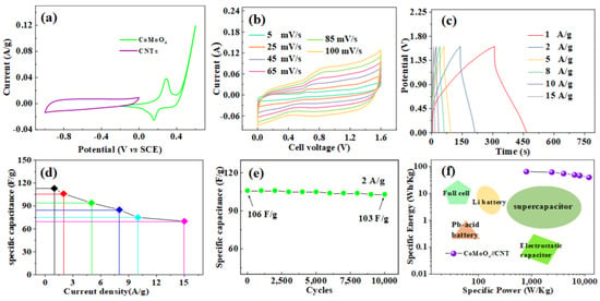
Figure 6.
(a) CV curves of CNTs and pie-shaped CoMoO4 electrodes performed in a three-electrode cell in a 2 M KOH electrolyte at a scan rate of 20 mV/s. (b) Cyclic voltammetry of the CoMoO4//CNT device tested at different sweep rates. (c) Charge–discharge curves of the CoMoO4//CNT device electrode at different current densities. (d) Specific capacitance diagram of CoMoO4//CNTs under different current densities. (e) Cycle performance of CoMoO4// CNT device for 10,000 times at the current density of 2 A/g. (f) Energy comparison diagram of various types of energy storage devices.
CoMoO4 has the advantages of good photocatalytic performance and environmental friendliness, and is dominant in many photocatalytic materials [,]. Photocatalysis is usually caused by photogenerated electron–hole pairs, which are the main factors affecting the performance of photocatalysis. Figure 7 shows the photocatalytic mechanism of cobalt molybdate. When illuminated at a certain wavelength, electrons absorb the energy emitted by the illuminated light and undergo a transition, the valence band loses electrons, leaving positively charged holes. The conduction band gains electrons and the organic state becomes an excited state. Electrons with negative electrical activity are present in the conduction band, and electron–hole pairs are formed. The electron–hole pair reacts with water or hydroxyl groups to produce free groups, which are powerful oxidants. It oxidizes large molecules in pollutants into CO2 and H2O. The reaction equation is as follows []:
Catalyst + hv → e− + h+
e− + O2 → ·O2−
O2− + 2H+ + 2e− → ·OH− + OH−
H2O2 → ·OH− +·OH
h+ + OH− → ·OH
h+ + H2O → ·OH + H+
h+ + H2O → H2O2 + 2H+
R − H + ·OH → ·R+ + H2O
R − H + h+ → ·R+ → CO2 + H2O
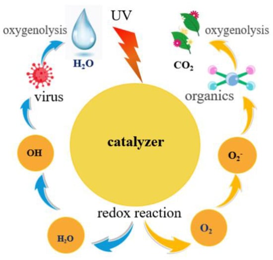
Figure 7.
Photocatalytic mechanism diagram.
The photocatalytic performance of CoMoO4 was further studied by exploring the degradation of MO, MB, CR, and other dyes by pie-shaped CoMoO4. Figure 8a shows the degradation curve of Mo dye degraded by CoMoO4 nanomaterial. It is clearly expressed in the figure that as the degradation time progresses, the absorbance value of the curve gradually decreases, which indicates that the dye is gradually degraded. After 100 min, the degradation rate reached 97.8%. Figure 8b shows the degradation curve of MB by CoMoO4 nanomaterial. With the extension of the degradation time, the absorbance of the curve gradually decreased, and the degradation rate reached 98.8% after 40 min. Figure 8c shows the degradation curve of CR by CoMoO4 nanomaterial. With the extension of degradation time, the absorbance value gradually decreases, indicating that the dye is degraded. After 65 min of degradation, the degradation rate was 99.6%. In the figure, it is clearly seen that the color of MO, MB, and CR changes from dark to light, and MB and CR are finally almost transparent, indicating that the degradation effect is very ideal. Figure 8d shows the comparison of the degradation of the three dyes. The results show that the CR dye had the shortest degradation time and the best degradation effect.
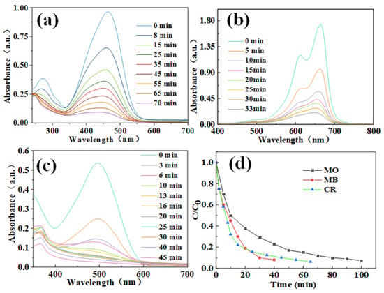
Figure 8.
Photocatalytic degradation curves of different dyes (a) MO. (b) MB. (c) CR. And (d) Dye degradation rate curve.
In order to further study whether the material has a recovery value, we explored the cyclic stability test of CR degradation in pie-shaped CoMoO4, as shown in Figure 9. After each degradation of the sample for recycling, the CoMoO4 nanoparticles degradation of CR found that there was very little change between the initial point and the end point. This indicates that CoMoO4 nanoparticles still have a good degradation effect on CR after 15 cycles of experiments. We compare our work with other literature, as shown in Table 2. In addition, we also used the Langmuir–Hinshelwood model to fit the zero-order, first-order, and second-order kinetic equations for the photodegradation of MO, RhB, and CR by CoMoO4. The reaction rate constant can reflect the speed of photodegradation. The larger the correlation coefficient (R) of the kinetic equation, the higher the fitting degree []. Relevant data are shown in Table 3. The R values of the first-order kinetics model of the photodegradation of the three target pollutants were all greater than those of the zero-order and the second-order, which indicates that the photodegradation of MO, RhB, and CR by CoMoO4 was more consistent with the first-order kinetics model. By comparing the reaction rate constant (slope), it can be seen that RhB has the highest slope, indicating that the RhB photodegradation reaction is faster. This is consistent with the experimental results.
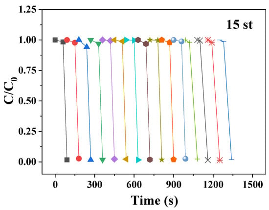
Figure 9.
Cycles performances of CR.

Table 2.
Degradation efficiency of dyes by materials.

Table 3.
The photocatalytic degradation kinetics of MO, RhB, and CR.
4. Conclusions
In this paper, the pie-shaped CoMoO4 nanomaterials were prepared by a simple solvothermal method. The pie-shaped CoMoO4 has a high specific capacitance (1902 F/g at 1 A/g) and good cycling performance (99.5% at 10,000 cycles at 15 A/g) when used as a supercapacitor electrode material. We assembled the asymmetric device CoMoO4//CNTs by using it and CNTs as the positive and negative electrodes of the supercapacitor, respectively. The device has a high specific capacitance (118 F/g at 1 A/g) and excellent capacity maintenance (97.2% at 10,000 cycles). This shows good energy storage capacity. At the same time, the pie-shaped CoMoO4 also showed good photocatalytic performance when used as a photocatalytic material. The degradation rates of MO, MB, and RhB were all over 97.8%. In addition, it also has good cyclic stability, a cyclic degradation of 15 times, and still has a good degradation effect. The CoMoO4 nanomaterials prepared above have been widely used in the field of supercapacitor electrode materials and photocatalysis.
Author Contributions
S.C. designed this experiment and carried out the experiments. G.W. and J.W. (Juan Wu) wrote the manuscript and other analyses. G.W. and J.W. (Jing Wang) carried out the characterization tests, analyzed, wrote the results, and revised the manuscript. Y.L. (Yang Li), H.W., Y.L. (Yang Liu), J.G. and M.Y. analyzed the characterization tests and wrote and revised the manuscript. M.Y., L.F., J.H., L.F., J.H., S.W. and Y.L. (Yang Liu) analyzed and discussed the results. All authors have read and agreed to the published version of the manuscript.
Funding
This research work was supported by the Young Scientific Research Item of Harbin University of Commerce (18XN034), the National Natural Science Foundation of China (No. 52002099), the Foundation of State Key Laboratory of High-Efficiency Utilization of Coal and Green Chemical Engineering (Grant No. 2022-K74), and College Students’ Innovative Entrepreneurial Training Plan Program (No. S202210240002).
Institutional Review Board Statement
Not applicable.
Informed Consent Statement
Not applicable.
Data Availability Statement
The data presented in this study are available in this article.
Conflicts of Interest
The authors declare no conflict of interest.
References
- Irfan, R.M.; Tahir, M.H.; Iqbal, S.; Nadeem, M.; Bashir, T.; Maqsood, M.; Gao, L. Co3C as a promising cocatalyst for superior photocatalytic H2 production based on swift electron transfer processes. J. Mater. Chem. C 2021, 9, 3145–3154. [Google Scholar] [CrossRef]
- Tang, W.; Zhu, Y.; Hou, Y.; Liu, L.; Wu, Y.; Loh, K.P.; Zhang, H.; Zhu, K. Aqueous rechargeable lithium batteries as an energy storage system of superfast charging. Energy Environ. Sci. 2013, 6, 2093–2104. [Google Scholar] [CrossRef]
- Edrissi, M.; Samadanian-Isfahani, S.; Soleymani, M. Preparation of cobalt molybdate nanoparticles; Taguchi optimization and photocatalytic oxidation of Reactive Black 8 dye. Powder Technol. 2013, 249, 378–385. [Google Scholar] [CrossRef]
- Majumdar, D.; Mandal, M.; Bhattacharya, S.K. Journey from supercapacitors to supercapatteries: Recent advancements in electrochemical energy storage systems. Emergent Mater. 2020, 3, 347–367. [Google Scholar] [CrossRef]
- Olabi, A.G.; Abbas, Q.; Al Makky, A.; Abdelkareem, M.A. Supercapacitors as next generation energy storage devices: Properties and applications. Energy 2022, 248, 123617. [Google Scholar] [CrossRef]
- Salunkhe, R.R.; Lee, Y.H.; Chang, K.H.; Li, J.M.; Simon, P.; Tang, J.; Torad, N.L.; Hu, C.C.; Yamauchi, Y. Nanoarchitectured Graphene-Based Supercapacitors for Next-Generation Energy-Storage Applications. Chem. Eur. J. 2014, 20, 13838–13852. [Google Scholar] [CrossRef] [PubMed]
- Du, X.; Yang, L.; Fu, Y.; Liu, S.; Huang, N.; Wang, S. Microwave-Assisted Synthesis of NiMn2O4 Grown on Nickel Foam as Electrode Material for High-Performance Supercapacitors. ChemistrySelect 2021, 6, 5567–5574. [Google Scholar] [CrossRef]
- Zhang, L.; Zheng, S.; Wang, L.; Tang, H.; Xue, H.; Wang, G.; Pang, H. Fabrication of Metal Molybdate Micro/Nanomaterials for Electrochemical Energy Storage. Small 2017, 13, 1700917. [Google Scholar] [CrossRef]
- Wu, N.; Bai, X.; Pan, D.; Dong, B.; Wei, R.; Naik, N.; Patil, R.R.; Guo, Z. Recent Advances of Asymmetric Supercapacitors. Adv. Mater. Interfaces 2021, 8, 2001710. [Google Scholar] [CrossRef]
- Ahmad, K.; Mobin, S.M. Shape controlled synthesis of high surface area MgO microstructures for highly efficient congo red dye removal and peroxide sensor. J. Environ. Chem. Eng. 2019, 7, 103347. [Google Scholar] [CrossRef]
- Dong, X.-W.; Zhang, Y.-Y.; Wang, W.-J.; Zhao, R. Rational construction of 3D NiCo2O4@CoMoO4 core/shell nanoarrays as a positive electrode for asymmetric supercapacitor. J. Alloys Compd. 2017, 729, 716–723. [Google Scholar] [CrossRef]
- Zhang, P.; Zhang, X.; Li, G. Fabrication of rod-like NiMoO4/CoMoO4 for application in asymmetric supercapacitors. Ionics 2020, 26, 393–401. [Google Scholar] [CrossRef]
- Ma, T.; Wu, Y.; Liu, N.; Tao, X.; Wu, Y. Iron-doped g-C3N4 modified CoMoO4 as an efficient heterogeneous catalyst to activate peroxymonosulfate for degradation of organic dye. J. Dispers. Sci. Technol. 2021, 43, 80–93. [Google Scholar] [CrossRef]
- Shaheen, I.; Ahmad, K.S.; Thomas, A.G.; Compeán-González, C.L.; Jones, R.; Malik, M.A. Synthesis and analysis of ZnO-CoMoO 4 incorporated organic compounds for efficient degradation of azo dye pollutants under dark ambient conditions. Appl. Organomet. Chem. 2020, 34, e5733. [Google Scholar] [CrossRef]
- Wang, J.; Zhang, X.; Wei, Q.; Lv, H.; Tian, Y.; Tong, Z.; Mai, L. 3D self-supported nanopine forest-like Co3O4@CoMoO4 core–shell architectures for high-energy solid state supercapacitors. Nano Energy 2016, 19, 222–233. [Google Scholar] [CrossRef]
- Wang, J.; Liu, S.; Zhang, X.; Liu, X.; Liu, X.; Li, N.; Zhao, J.; Li, Y. A high energy asymmetric supercapacitor based on flower-like CoMoO4/MnO2 heterostructures and activated carbon. Electrochim. Acta 2016, 213, 663–671. [Google Scholar] [CrossRef]
- Yu, X.; Lu, B.; Xu, Z. Super Long-Life Supercapacitors Based on the Construction of Nanohoneycomb-Like Strongly Coupled CoMoO4-3D Graphene Hybrid Electrodes. Adv. Mater. 2014, 26, 1044–1051. [Google Scholar] [CrossRef] [PubMed]
- Prabhu, S.; Gowdhaman, A.; Harish, S.; Navaneetham, M.; Ramesh, R. Synthesis of petal-like CoMoO4/r-GO composites for high performances hybrid supercapacitor. Mater. Lett. 2021, 295, 129821. [Google Scholar] [CrossRef]
- Gao, Y.; Tao, J.; Li, J.; Xie, H.; Li, Y.; Wang, T.; Zhang, C. Construction of CoMoO4 nanorods wrapped by Ni-Co-S nanosheets for high-performance supercapacitor. J. Alloys Compd. 2022, 925, 166705. [Google Scholar] [CrossRef]
- Luo, Y.; Zhang, H.; Guo, D.; Ma, J.; Li, Q.; Chen, L.; Wang, T. Porous NiCo2O4-reduced graphene oxide (rGO) composite with superior capacitance retention for supercapacitors. Electrochim. Acta 2014, 132, 332–337. [Google Scholar] [CrossRef]
- Mai, L.-Q.; Yang, F.; Zhao, Y.-L.; Xu, X.; Xu, L.; Luo, Y.-Z. Hierarchical MnMoO4/CoMoO4 heterostructured nanowires with enhanced supercapacitor performance. Nat. Commun. 2011, 2, 381. [Google Scholar] [CrossRef] [PubMed]
- Xuan, H.; Li, H.; Yang, J.; Liang, X.; Xie, Z.; Han, P.; Wu, Y. Rational design of hierarchical core-shell structured CoMoO4@CoS composites on reduced graphene oxide for supercapacitors with enhanced electrochemical performance. Int. J. Hydrogen Energy 2020, 45, 6024–6035. [Google Scholar] [CrossRef]
- Ge, J.; Wu, J.; Fan, L.; Bao, Q.; Dong, J.; Jia, J.; Guo, Y.; Lin, J. Hydrothermal synthesis of CoMoO4/Co1-xS hybrid on Ni foam for high-performance supercapacitors. J. Energy Chem. 2018, 27, 478–485. [Google Scholar] [CrossRef]
- Nasser, R.; Wang, X.-L.; Tiantian, J.; Elhouichet, H.; Song, J.-M. Hydrothermal design of CoMoO4@CoWO4 core-shell heterostructure for flexible all-solid-state asymmetric supercapacitors. J. Energy Storage 2022, 51, 104349. [Google Scholar] [CrossRef]
- Iro, Z.S.; Subramani, C.; Dash, S. A Brief Review on Electrode Materials for Supercapacitor. Int. J. Electrochem. Sci. 2016, 11, 10628–10643. [Google Scholar] [CrossRef]
- Wang, Q.; Jiao, L.; Du, H.; Wang, Y.; Yuan, H. Fe3O4 nanoparticles grown on graphene as advanced electrode materials for supercapacitors. J. Power Sources 2014, 245, 101–106. [Google Scholar] [CrossRef]
- Acharya, J.; Pant, B.; Ojha, G.P.; Kong, H.-S.; Park, M. Engineering triangular bimetallic metal-organic-frameworks derived hierarchical zinc-nickel-cobalt oxide nanosheet arrays@reduced graphene oxide-Ni foam as a binder-free electrode for ultra-high rate performance supercapacitors and methanol electro-oxidation. J. Colloid Interface Sci. 2021, 602, 573–589. [Google Scholar] [CrossRef]
- Liu, X.; Kong, L.T.; Hujiabudula, M.; Xu, S.; Ma, F.; Zhou, H.M.; Liu, J.M.; Abulikemu, A. Progress in preparation and photocatalytic properties of molybdate. Appl. Chem. Ind. 2021, 50, 217–224. [Google Scholar] [CrossRef]
- Tao, B.; Li, J.; Miao, F.; Zang, Y. Core shell structure CoMoO4@CuCo2O4 hybrids as advanced electrode materials for high-performance asymmetric supercapacitors. Ionics 2021, 27, 3627–3637. [Google Scholar] [CrossRef]
- Shahabuddin, S.; Sarih, N.M.; Ismail, F.H.; Shahid, M.M.; Huang, N.M. Synthesis of chitosan grafted-polyaniline/Co3O4 nanocube nanocomposites and their photocatalytic activity toward methylene blue dye degradation. RSC Adv. 2015, 5, 83857–83867. [Google Scholar] [CrossRef]
- Warkhade, S.K.; Zodape, S.P.; Pratap, U.R.; Wankhade, A.V. Rutile TiO2/CoSe nanocomposite: An efficient photocatalyst for photodegradation of model organic dyes under visible light irradiation. J. Mol. Liq. 2018, 279, 434–443. [Google Scholar] [CrossRef]
- Achary, L.S.K.; Barik, B.; Dash, P. Graphene Oxide-Polymer Nanocomposites Towards Sensing and Photocatalytic Applications. In Handbook of Polymer and Ceramic Nanotechnology; Springer: Berlin/Heidelberg, Germany, 2021; pp. 965–986. [Google Scholar]
- Destiarti, L.; Sasri, R. Application of Titanium-Silica-Graphite Composite Material for Photocatalytic Process of Methylene Blue. Indones. J. Chem. 2020, 20, 1271–1282. [Google Scholar] [CrossRef]
- Nawaz, A.; Saravanan, P. C-Dot TiO2nanorod composite for enhanced quantum efficiency under direct sunlight. RSC Adv. 2020, 10, 19490–19500. [Google Scholar] [CrossRef]
- Liang, J.; Fu, L. Activation of peroxymonosulfate (PMS) by Co3O4 quantum dots decorated hierarchical C@Co3O4 for degradation of organic pollutants: Kinetics and radical-nonradical cooperation mechanisms. Appl. Surf. Sci. 2021, 563, 150335. [Google Scholar] [CrossRef]
- Ahmad, K.; Shinde, M.A.; Kim, H. Molybdenum disulfide/reduced graphene oxide: Progress in synthesis and electro-catalytic properties for electrochemical sensing and dye sensitized solar cells. Microchem. J. 2021, 169, 106583. [Google Scholar] [CrossRef]
Publisher’s Note: MDPI stays neutral with regard to jurisdictional claims in published maps and institutional affiliations. |
© 2022 by the authors. Licensee MDPI, Basel, Switzerland. This article is an open access article distributed under the terms and conditions of the Creative Commons Attribution (CC BY) license (https://creativecommons.org/licenses/by/4.0/).