Article

Improving the Efficiency of Air Plasma Spraying of Titanium Nitride Powder

by
Aidar Kengesbekov
1,2,
Bauyrzhan Rakhadilov
2,
Zhuldyz Sagdoldina
1,*,
Dastan Buitkenov
1,
Yelmurat Dosymov
3 and
Manarbek Kylyshkanov
4
1
Research Center «Surface Engineering and Tribology», Sarsen Amanzholov East Kazakhstan University, Ust-Kamenogorsk 070000, Kazakhstan
2
PlasmaScience LLP, Ust-Kamenogorsk 070000, Kazakhstan
3
Department of Physics, Khoja Akhmet Yassawi International Kazakh-Turkish University, Turkistan 161205, Kazakhstan
4
JSC “Ulba Metallurgical Plant”, Ust-Kamenogorsk 070000, Kazakhstan
*
Author to whom correspondence should be addressed.
Coatings 2022, 12(11), 1644; https://doi.org/10.3390/coatings12111644
Submission received: 4 October 2022 / Revised: 25 October 2022 / Accepted: 27 October 2022 / Published: 30 October 2022
(This article belongs to the Special Issue Surface Engineering and Tribology)

Abstract

:
The operation modes of a plasmatron for powder coating spraying have been studied. The plasmatron has a node of annular input and a gasdynamic focusing of the powder, and the outlet holes of the nozzle-anode are made in the form of rectangular narrowing-expanding channels (No.34334 RK: IPC H05H 1/42). The dynamics and trajectories of the powder particles in the plasmatron were investigated. The paper analyzes the influence of plasmatron arc current and working gas flow rate on the structure and properties of the obtained coatings. It is established that the phase composition of the sprayed coatings and the initial powder is the same: the main phase is the compound TiN, in addition, the structure contains the phase TiO2. The results of tribological tests of the coatings under dry friction conditions according to the ball-on-disk scheme are presented. Within the framework of this study, it can be said, from the point of view of obtaining denser coatings with high performance characteristics, that the optimal modes of plasma spraying of TiN powder are a current of 250 A and the working gas flow rate of argon 34 L/min.

1. Introduction

In recent years, all industrialized plants have been intensively developing technologies for creating wear-resistant materials and methods for applying coatings based on nitrides. Titanium nitride (TiN) has excellent wear resistance, erosion resistance, heat resistance and low friction coefficient [1,2,3,4,5], so it is widely used in some areas as hard, wear-resistant coatings. The choice of TiN coating deposition methods is determined by geometric parameters of coated parts and articles, their design and technological features, conditions of future operation, as well as the required thickness of the functional protective layer [6,7,8,9,10]. The most common methods for obtaining TiN coatings are CVD and PVD methods. Right after the deposition of TiC films (around 1960), TiN followed very shortly [11,12,13,14]. However, due to the low efficiency of deposition, the thicknesses of these coatings are very thin (<10 mm) [15]. Works [16,17] show that the performances of TiN coating depend on its thickness; for example, the thicker the TiN coating, the better the wear resistance and corrosion resistance. Moreover, if the thickness of the TiN coating is less than 12 mm, it would not be able to resist the osmosis of corrosives. Therefore, making the TiN coating thick is a clever way to obtain better performance.
To date, the following coating deposition methods are most widely used in industry [18,19,20]: detonation spraying; high velocity oxygen fuel (HVOF); air plasma spraying. Each of the above methods has its advantages and disadvantages determining its effective area of application, but the first two methods can be implemented only in the presence of special chambers and gas communications. Moreover, their application is also limited by energy problems arising during heating of large-sized parts, since the required density and adhesion are achieved by the subsequent heat treatment of the formed layer. Therefore, one of the most economical and easy-to-implement TiN coating deposition methods is the air plasma spraying method, which allows for the formation and melting of the layer in a single operation.
Using plasma spraying technology to obtain a thick TiN coating has been reported in the former references [1,2,21]. T. Bacci [2] has prepared a TiN coating with a thickness of 60 mm using reactive plasma spraying, and the spraying was performed in a pure nitrogen atmosphere chamber at 500 bar. However, the coating was mainly composed of the residual Ti and some TiN, Ti2N. Akira Kobayashi [1], using a gas tunnel-type plasma jet, prepared a TiN coating whose thickness was over 200 mm. In addition, Wenran Feng [21,22] especially studied the microhardness and tribological properties of the reactive plasma sprayed TiN coating; E. Galvanetto [23] investigated the formation of titanium nitrides during the reactive spraying of titanium by means of XRD and XPS. However, all the previous studies on the plasma spraying of TiN were carried out in the nitrogen-containing spraying chamber or using a gas tunnel-type plasma jet; spraying that is carried out in the air has not been found in the former references.
The present work is focused on studying the influence of air plasma spraying parameters on the structure and properties of powder coatings.
The essence of air-plasma spraying is [24,25,26] that powder particles pass through a zone of ionized gas (plasma) formed by an electric gas discharge, are melted, and deposited on the substrate surface heated in the contact zone in the course of coating formation. The main element of technological equipment is a plasmatron that combines the functions of a plasma source and atomizer of disperse material. Plasma-forming gas (argon, nitrogen, air) passes through the area of an electric arc, ionizes, and exits through the nozzle of the plasma gun in the form of a plasma stream (flow). In most technological processes of plasma treatment of materials, most often used are electric arc linear plasmatrons, which, compared to plasmatrons of other schemes, have a simple design, a relatively long life of the electrodes, the possibility of controlling the discharge power not only by changing the arc current, but also by changing the arc voltage.

2. Technology and Methods

Experimental air-plasma spraying setup designed for surface treatment with plasma and application of powder coatings at atmospheric pressure was developed. The setup includes a plasmatron, a power supply, a control panel, a switching module with a start-up block, a dispenser and an autonomous plasmatron cooling module. Figure 1 schematically shows the setup for obtaining powder coatings which includes: plasmatron 1 consisting of anode 2, cathode 3, interelectrode ceramic insertion 4, tubes 5 for feeding plasma gas-argon 6, tubes 7 for feeding inert gas-nitrogen 8 and sprayed powder 9, fittings for input 10 and output 11 of cooling fluid 12, powder dosing device 13, power supply 14, self-contained water cooling block 15.
The setup works in the following mode. Before starting work, the cooling system is switched on. To cool the plasmatron, distilled water is used, which enters the cavity of the anode assembly case through the fitting, and then the heated water is discharged through the fitting. The coolant is in circulating mode and the temperature of the coolant is automatically regulated by an autonomous water-cooling module. Then the plasma-forming gas-argon is fed through the radial feed tube of the cathode node, into the discharge area of the plasmatron. When voltage is applied to the electrodes, an electric arc occurs between the nozzle-anode and the cathode and the plasma-forming gas-argon is ionized and exits the nozzle-anode at high speed, forming a stream of plasma. The dispenser is then connected via an inert gas channel and the powder to be sprayed is fed into the plasma stream.
Plasmatron (Figure 2) is a DC thermal plasma generator of coaxial design with a tungsten cathode 5 mm in diameter, built into the copper rod in the center, and an all-welded nozzle anode of copper, which has a radiator profile which can disassemble and assemble the plasmatron during repair work without reducing its quality [27]. The key element of the plasmatron design is a node of annular input and gas-dynamic focusing of the powder, and the outlet holes of the nozzle-anode are made in the form of rectangular narrowing-expanding channels. This design scheme provides input of the sprayed powder into the axial high-temperature and high-speed part of the plasma flow, which significantly increases the efficiency of heating and acceleration of particles and sputtering productivity. The powder annular input node directly behind the anode binding zone of the arc discharge makes it possible to significantly increase the efficiency of interaction of the plasma jet with the powder, which significantly increases the quality of coatings and the productivity of material processing. The use of the annular input node contributes to more efficient heating of the particles and increases the maximum treatment productivity by more than one order of magnitude, as compared to one-sided point input [28]. AC electric arc plasma gun operates with different gases (argon, nitrogen, helium, air) with maximum power up to 34 kW at low pressure of about 0.01 MPa.
To provide a given spraying mode and simultaneously increase the thermal efficiency, it is advisable to simulate the design of the plasmatron and the processes occurring in it. Figure 3 shows the flow paths and velocity distribution gradient at a working pressure of 5 atm. The dependence of velocity on the working gas pressure and the trajectory of gas in the plasmatron has been determined. The color diffraction of the velocities of the working gas and the flow trajectory, was calculated using SoIidWorks mathematical aerodynamic modeling program [29,30]. Each color on the scale corresponds to a particular gas velocity in a particular area. Thus, the blue color corresponds to speeds from 111 to 166 m/s (which corresponds to the initial gas speed), green—from 222 to 277 m/s, yellow—from 333 m/s to 388. The dependence of the average gas velocity on the operating gas pressure 1–8 atm was investigated (Figure 3). The graph shows that to ensure sufficient particle dynamics, it is necessary to operate the plasmatron in the pressure range of 3–5 atm.
Then, the dynamics and trajectories of the powder particles were investigated when they were introduced into the swirler channel (Figure 4). The study was carried out without sticking and erosion conditions. Titanium nitride of a fraction of 5 µm was used as the powder (conditional flow rate of the powder is 0.005 kg/s). The powder particle trajectory in the nozzle area was calculated, which corresponds to the average velocity value of ≈220 m/s, as shown in Figure 4b. The particle travel length in the plasmatron is up to 500 mm, and in the plasma zone (nozzle area) it is about 150 mm.
Stainless steel 12Kh18N10T (analog AISI 321) (0.12 wt.%C, 18 wt.%Cr, 10 wt.%Ni, Ti) was used as a substrate material. To improve the adhesion between the coating and the substrate, the flat surface of a 50 × 50 × 4 mm steel sample was cleaned in acetone and sandblasted before spraying. TiN powder with a dispersion of 15–40 μm was used for spraying the coatings.
An air plasma spraying system was used for the experiment (Figure 1). Before sputtering, the substrate was preheated to 250 °C using a plasma jet, which was controlled by a HT-819-pyrometer. Then TiN coatings were applied to the substrate using a plasmatron. The surface morphology was studied by scanning electron microscopy on a JSM-6390 scanning electron microscope with energy dispersive spectrometer (EDS).
The phase composition of the studied samples was studied using X-ray diffractometer X’Pert8 Pro (Philips Corporation, the Netherlands) using CuKα radiation. Imaging was performed in the following modes: tube voltage U = 40 kV; tube current I = 30 mA; exposure time 1 s; imaging step 0.02°.
Tribological tests for sliding friction were performed on a TRB3 tribometer (Anton Paar, Austria) using standard ball-on-disk technology (Figure 5) (ASTM International Standards G 99) [31]. A counterbody consisting of a 6.0 mm diameter ball made of Si3N4 coated steel was used. Tests were performed at a load of 6 N and a linear velocity of 3 cm/s, with a radius of curvature of wear of 4 mm and a friction path of 100 m. Assessment of roughness was carried out by a standard method (GOST 2789-73) with a profilometer factory “Proton” model 130. Adhesion measurements were made with automatic adhesion tester Elcometer 510 in accordance with the standard specification ASTM D 4541, the adhesive was a two-component epoxy system (Araldite), the pulley diameter was 20 mm. After the pulleys were bonded, the adhesive was cured for 24 h at 24 °C and 50% relative humidity.
A CSEMMicroScratchTester scratch tester was used to examine the adhesion characteristics of the coatings by scratching. The scratch test was carried out at a maximum load of 30 N, scratch length—10 mm, the radius of curvature of the tip—100 µm. For the obtained coatings, the mechanical properties (Young’s modulus, hardness) were investigated using the NanoScan-4DCompact nanohardness tester. The tests were carried out at a load of 50 mN. Loading time 10 s, unloading time 10 s, maximum load holding time 2 s. Dependence of penetration depth on applied force at loading and unloading stages was determined by the Oliver-Farr method.
The quality of the coatings depends on several factors in air plasma spraying: spraying distance, current strength, voltage, and gas pressure. Among these factors, the electric current and the working gas (Ar) pressure play a significant role. In this regard, the following spraying parameters were selected for sputtering (Table 1).

3. Results and Discussion

Figure 6 shows the diffractogram of TiN coating deposited on the surface of 12Kh18N10T (analog AISI 321) steel substrate. The coating mainly consists of two phases, TiN and a small amount of TiO2. The analysis of the diffractogram showed five main TiN peaks with the diffraction plane (111), (020), (132), (131) and (222) characteristic of the FCC structure phase. The diffraction peaks of TiO2 (104), (110), (105) have low intensities. TiO2 is a product of titanium oxidation due to the decomposition of TiN powder during the APS process.
The cross-sectional microstructure of the coatings is shown in Figure 7. The thickness of the coatings for all studied samples is ~70 µm. The coating is a lamellar structure, which is densely folded. The results of SEM studies testify to the inhomogeneous structure of the obtained coatings related to the non-uniformity of the powder particles heating in the plasma jet. Weakly deformed particles are found in the coating material and cracks are observed inside the weakly deformed particles, which are formed when insufficiently heated particles collide with the substrate or with the cooled material of the formed coating, which is typical for thermal spraying methods. On the one hand, the cracks can be caused by the melting of the powder during the HVP, and on the other hand, by the difference in the coefficients of thermal expansion between the powder particles and the matrix, which created the thermal stress that provides the source of the cracking. The data obtained by X-ray phase analysis are confirmed by the result of EDS analysis (Table 2).
Figure 8 shows the adhesion strength and roughness of the TiN coatings obtained at different APS modes. It follows from the results that the adhesion of the coating increases with a decrease in the surface roughness of the sprayed layer. The TiN(1) coating showed good results compared to the TiN(2) and TiN(3) coatings. The adhesion strength of the coatings was determined by the tear-off method. The analysis of the character of the coatings failure showed that in all tests of the coatings the tearing occurs on the adhesive. In this case, the force corresponding to the adhesion of the coating to the metal base is not determined. In this case, the adhesion strength of the coatings can be thought of as a force that is equal to or greater than the glue-based tear force, this type of tear is a positive result. However, it follows from these data that it is impossible to accurately determine the adhesion strength of gas-thermal coatings if it is greater than the adhesive tensile strength, because the adhesive bond is the first to break when the load is applied, and other techniques must be used to determine it. Therefore, the adhesion strength of coatings was also tested by scratch testing.
The adhesion strength of the coating/substrate interface can be estimated by the threshold value of the critical load. Figure 9 shows that the friction force increases in an oscillatory manner as the applied load increases. Different coating regimes correspond to different acoustic emission (AE) values as a function of load. According to the coating test results, cohesive fracture begins at a minimum (Lc1) load of 2.2–2.5 N for TiN(2) coatings. The onset of the first crack at the indentation load Lc2 may be related to the adhesion fracture of the coatings. At load values Lc2 ≈ 11 N and Lc2 ≈ 6 N, coating delamination at the scratch edges of samples TiN(1) and TiN(3), respectively, was observed (Figure 9), which correlates with a sharp increase in the AE intensity. The comparative analysis indicates that the coatings scratch abrade but do not peel, i.e., they fail by the cohesive mechanism. The critical load corresponding to the cohesive-adhesion failure Lc3 was not determined in the tests up to the maximum experimental load of 30 N. The coatings obtained at different APS modes have good adhesion properties and did not experience any failure (chipping, delamination), which is clearly visible in the image of the track left by the diamond indenter on the coating. The improved bond strength for the TiN (1) coating is due to a stronger reaction at the coating/substrate interface, and this helped to form metallurgical compounds with high adhesion properties.
Figure 10 shows the results of hardness and modulus of elasticity measurements of TiN coatings obtained under different spraying modes. The measurement was made on a cross section of the coatings by the nanoindentation method. A total of 20 diamond indenter impressions were placed on each sample, with an indenter penetration depth of 150 nm Hardness is critical for the plastic deformation resistance of coatings, and elasticity can improve the fracture toughness and deformation resistance of coatings. The ratio between hardness (H) and elastic modulus (E) can be defined as the plasticity index (H/E) or the elastic deformation capacity of a material, which can be used to predict the wear behavior of the material [32]. The experimental results showed that the plasticity index (H/E) of the coatings obtained at TiN(1), TiN(2), TiN(3) differ from each other and have the following values, respectively: 0.074; 0.058; 0.071. Generally, the higher the H/E value, the better the wear resistance. These results correlate well with tribological test results. The sample TiN(1) showed high wear resistance relative to samples TiN(2) and TiN(3).
As a result, coatings with higher hardness and lower modulus of elasticity can weaken the interfacial tension and improve anti-wear characteristics [33]. The dependence of the friction coefficient of the studied samples on the friction path is shown in Figure 11. A similar curve can be observed for all samples, including a noticeably short “running-in” period, that is, the worn surface of the coatings and the counterbody were adapted to each other and then held in a stationary mode (region II, III). It was shown that the coefficient of friction of TiN(1) coatings with a Si3N4 counterbody under dry friction was lower compared to TiN(2), TiN(3) coatings, which indicates the relative wear resistance of the coatings under the same test conditions. Images of the wear path of the coatings were taken using a 3D profilometer. Evaluating the wear resistance of the samples based on the geometric parameters of the wear track, it can be said that the track width of the TiN(1) coating sample is significantly less compared to TiN(2) and TiN(3). The wear volume in general further proves the improved tribological characteristic of the test specimen with TiN(1) coating.
On the basis of the results of the mechanical and tribological studies, it is possible to determine the optimal APS mode for TiN coatings. The TiN(1) coating obtained at a current strength of 250 A and a working gas flow rate (Ar) of 34 l/min showed the best results of hardness and wear resistance relative to the TiN(2) and TiN(3) coatings. Increasing the working gas flow rate reduces the thermal energy to heat the sputtered particles. At the plasma gas flow rate higher that is than optimal values, the coating density and other sputtering efficiency indicators significantly decrease. Increasing the operating current leads to an increase in the maximum particle velocities and temperatures. However, in this work, the working gas flow rate changes insignificantly. Based on this the efficiency of the sputtering process depends on the operating current, which varies from 250 A to 450 A. For the plasmatron operating mode at 350 A and 450 A, the powder particles acquire higher velocity and are little in the active plasmatron, accordingly the quality of the obtained coatings decreases. This conclusion is confirmed by the results of SEM images of the coating cross-section structure (Figure 7), where the TiN(1) coatings have a denser and more homogeneous structure compared to the TiN(2) and TiN(3) coatings.

4. Conclusions

The obtained results allow us to make the following conclusions:
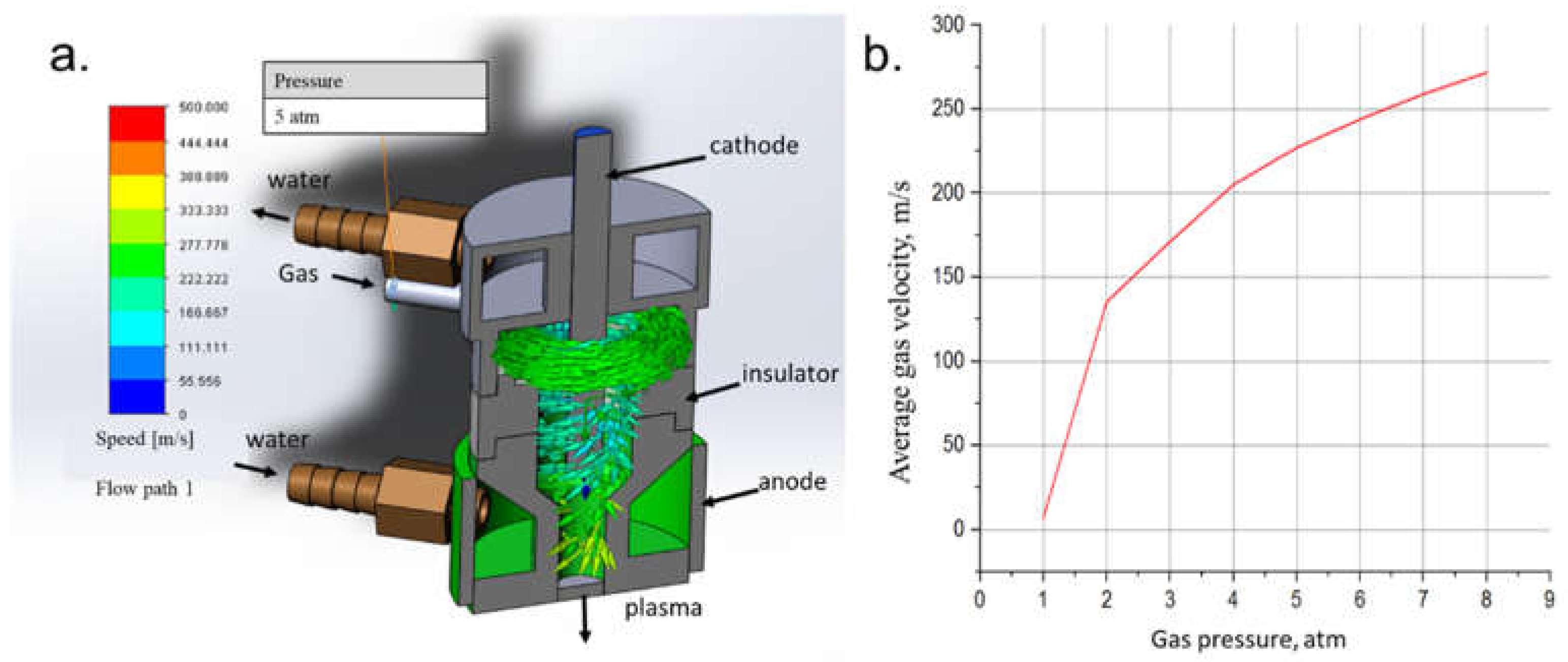
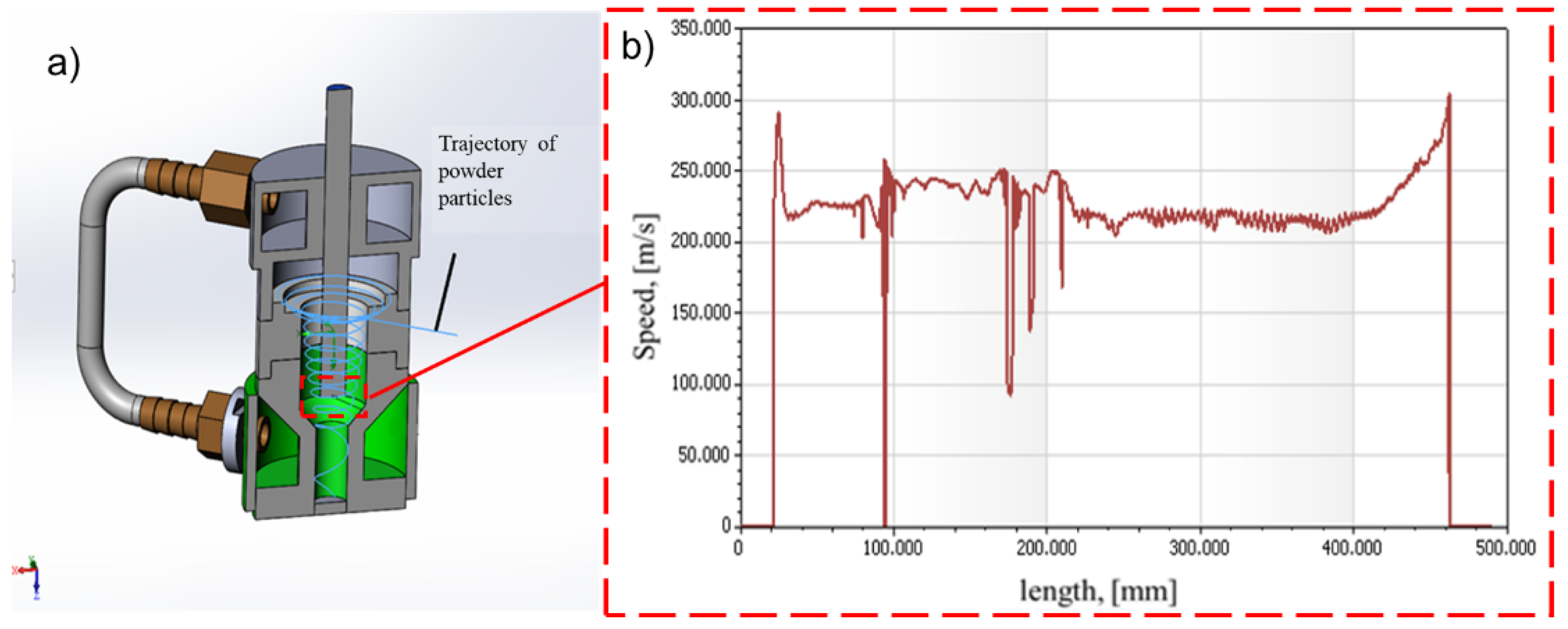
  • The possibility of TiN powder deposition on the steel surface by the APS method is shown. Powder of titanium nitride fraction of 5 microns is fed through an annular slit in the air-plasma jet and is sprayed on the preheated surface (up to 250 °C) with a plasma jet. The particle length of TiN powder in the plasmatron is up to 500 mm, in the plasma zone (nozzle area) it is about 150 mm, and the speed in the plasmatron nozzle area is ≈220 m/s;
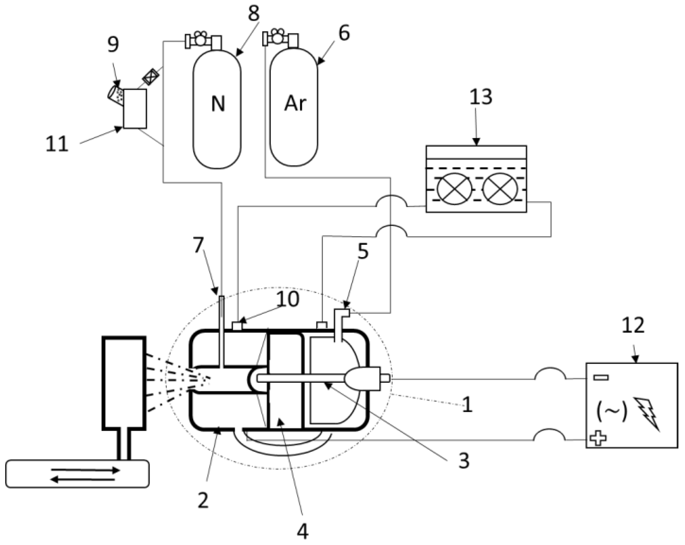
  • The optimum regime of APS for deposition of TiN powder was determined: the current is 250 A, the voltage is 68 V, the gas flow rate is 34 L/min, the spraying distance is 150 mm. To reduce the oxidation of TiN powder in the APS process, a method of creating a nitrogen environment at the outlet of the nozzle-anode, nitrogen flow rate 3 bar was used;
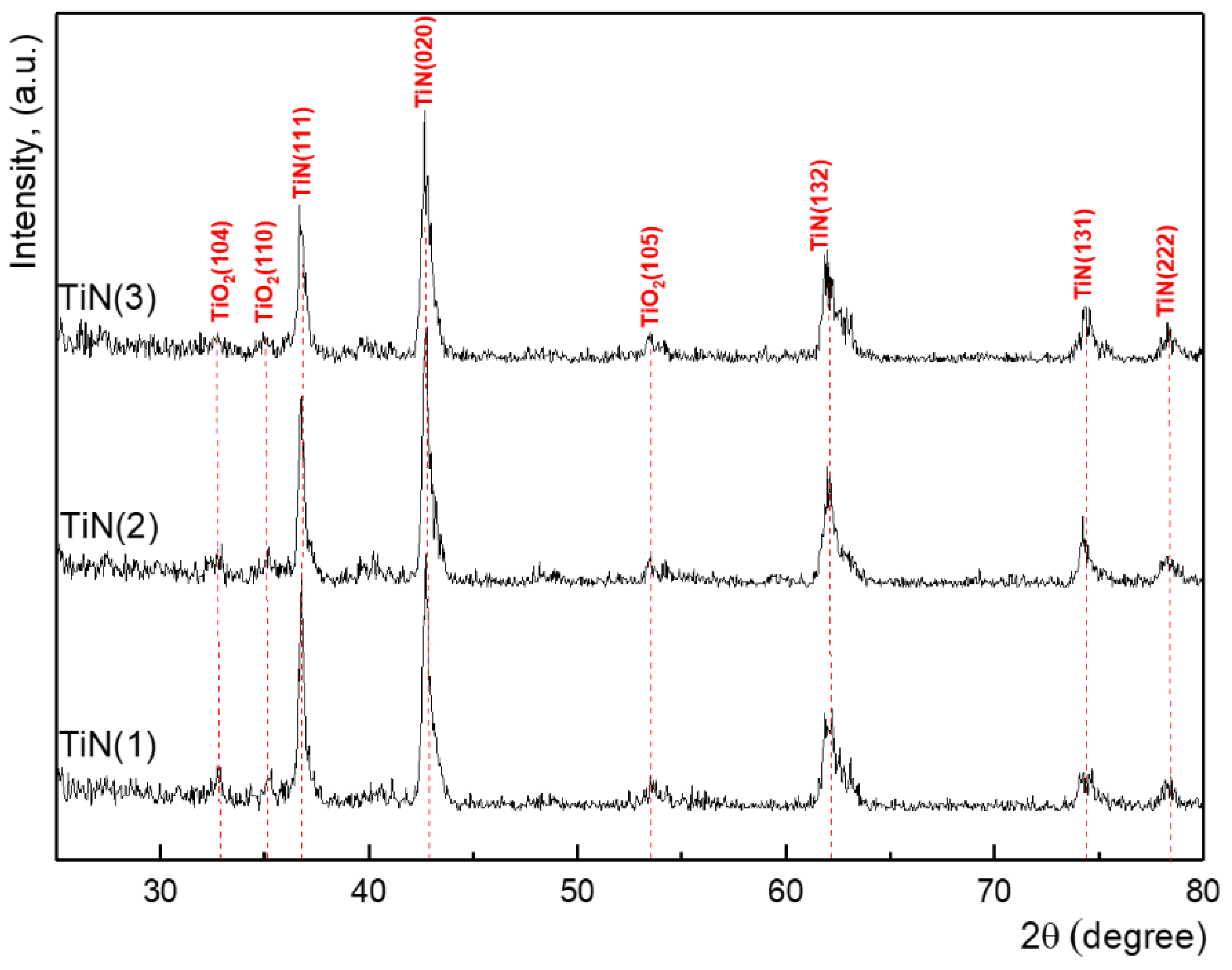
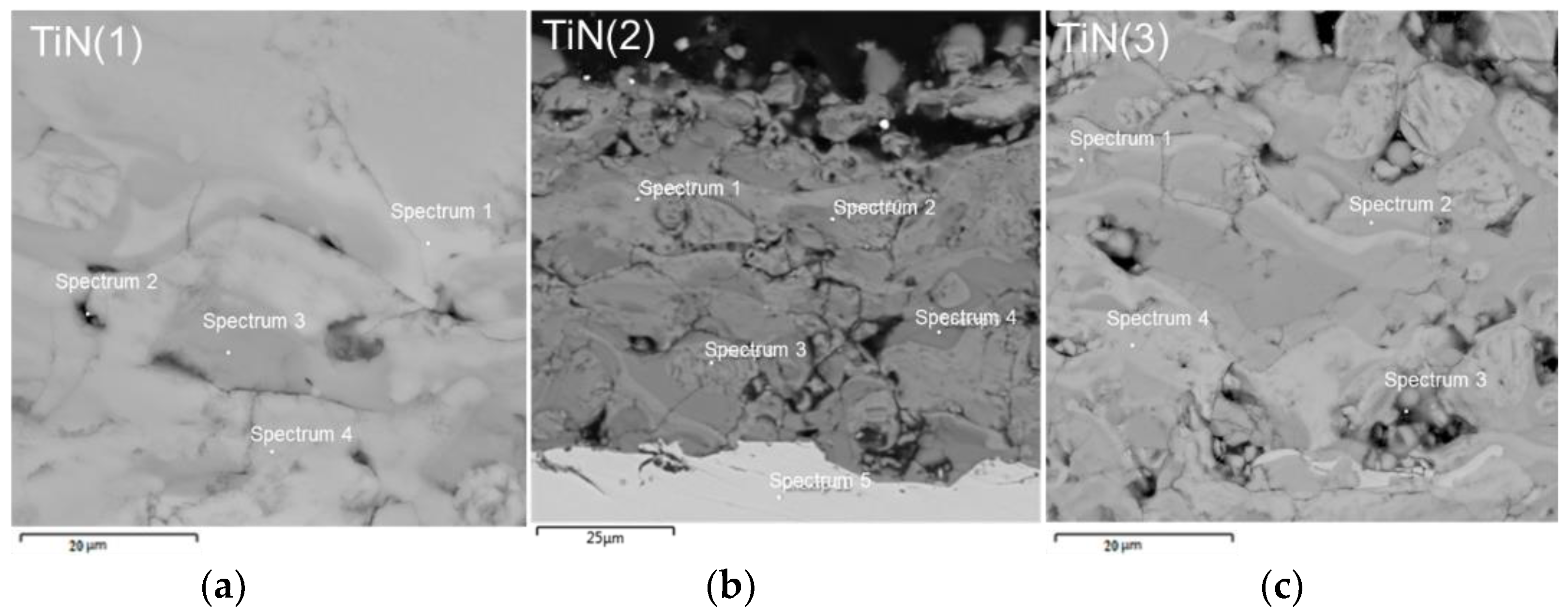
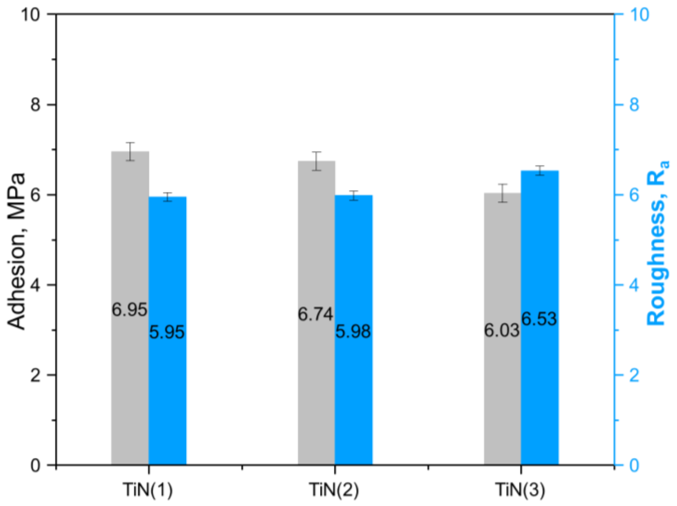
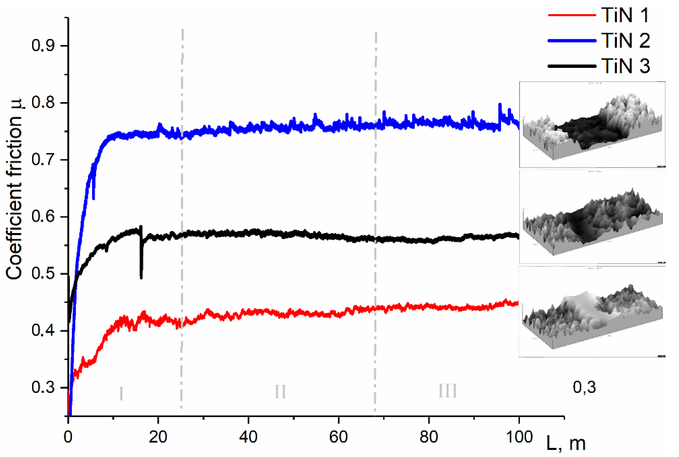
  • Microstructure of coatings is a lamellar structure with the presence of a small number of defects (cracks, pores) regardless of the application mode. The main coating phase is TiN. Increasing the spraying current causes the formation of a porous coating structure with a developed surface topography and leads to the deterioration of mechanical and tribological properties of the coatings.
Thus, the studies have shown the prospects and feasibility of using the APS technology to improve the wear resistance of stainless steel 12Kh18N10T (analog AISI 321).

Author Contributions

Z.S., B.R. and A.K. designed the experiments; A.K., Y.D. and D.B. performed the experiments; B.R., Z.S. and M.K. analyzed the data; Z.S., A.K. and B.R. wrote, reviewed and edited the paper. All authors have read and agreed to the published version of the manuscript.

Funding

This research has been funded by the Science Committee of the Ministry of Education and Science of the Republic of Kazakhstan (Grant No. AP08857733).

Institutional Review Board Statement

Not applicable.

Informed Consent Statement

Not applicable.

Data Availability Statement

Data is contained within the article.

Conflicts of Interest

The authors declare that there is no conflict of interest regarding the publication of this manuscript.

References

  1. Kobayashi, A. Formation of TiN coatings by gas tunnel type plasma reactive spraying. Surf. Coat. Technol. 2000, 132, 152–157. [Google Scholar] [CrossRef]
  2. Zou, D.L.; Yan, D.R.; He, J.N.; Li, X.Z.; Dong, Y.C.; Zhang, J.X. Reactive Plasma sprayed TiN coating and its thermal stability. J. Iron Steel Res. Int. 2007, 14, 71–75. [Google Scholar] [CrossRef]
  3. Shinde, S.V.; Sampath, S. Factors governing segmentation crack characteristics in air plasma sprayed ceramics. J. Eur. Ceram. Soc. 2022, 42, 1077–1087. [Google Scholar] [CrossRef]
  4. Li, G.; Zhang, L.; Cai, F.; Yang, Y.; Wang, Q.; Zhang, S. Characterization and corrosion behaviors of TiN/TiAlN multilayer coatings by ion source enhanced hybrid arc ion plating. Surf. Coat. Technol. 2019, 366, 355–365. [Google Scholar] [CrossRef]
  5. Xian, G.; Xiong, J.; Fan, H.; Jiang, F.; Guo, Z.; Zhao, H.; Liu, Y. Investigations on microstructure, mechanical and tribological properties of TiN coatings deposited on three different tool materials. Int. J. Refract. Met. Hard Mater. 2022, 102, 105700. [Google Scholar] [CrossRef]
  6. Rakhadilov, B.; Kenesbekov, A.; Skakov, M.; Miniyzov, A. Hydrogen and deuterium storage in tungsten when irradiation with Plasma beam. In Proceedings of the METAL 2018-27th International Conference on Metallurgy and Materials, Brno, Czech, 23–25 May 2018; pp. 1216–1221. [Google Scholar]
  7. Rahadilov, B.K.; Zhurerova, L.G.; Sagdoldina, Z.B.; Kenesbekov, A.B.; Bayatanova, L.B. Morphological Changes in the Dislocation Structure of Structural Steel 20GL after Electrolytic-Plasma Hardening of the Surface. J. Surf. Investig. X-Ray Synchrotron Neutron Tech. 2021, 15, 408–413. [Google Scholar] [CrossRef]
  8. Sharma, A.; Pathak, D.; Sharma, D.P.; Nunzi, J.M. Recent advances in bulkheterojunction solar cells: A Review. Eur. Phys. J. Appl. Phys. 2022. [Google Scholar] [CrossRef]
  9. Liu, K.; Chen, X.; Du, K.; Wang, Y.; Du, J.; Wang, X.; Ming, W. LC/8YSZ TBCs Thermal Cycling Life and Failure Mechanism under Extreme Temperature Gradients. Coatings 2021, 11, 1051. [Google Scholar] [CrossRef]
  10. Liu, K.; Bai, Y.; Li, J.; Ma, J.; Du, J.; Cao, Y.; Li, X. Structure-property relationship and design of plasma-sprayed La2Ce2O7/8YSZ composite coatings for gas turbine blades. Ceram. Int. 2018, 44, 13662–13673. [Google Scholar] [CrossRef]
  11. Lee, S.Y.; Chung, J.W.; Kim, K.B.; Han, J.G.; Kim, S.S. Duplex plasma surface treatment process on mild steel and high alloyed tool steel. Surf. Coat. Technol. 1996, 86, 325–331. [Google Scholar] [CrossRef]
  12. Schönjahn, C.; Bamford, M.; Donohue, L.; Lewis, D.; Forder, S.; Münz, W.-D. The interface between TiAlN hard coatings and steel substrates generated by high energetic Cr+ bombardment. Surf. Coat. Technol. 2000, 125, 66–70. [Google Scholar] [CrossRef]
  13. Stoiber, M.; Perlot, S.; Mitterer, C.; Beschliesser, M.; Lugmair, C.; Kullmer, R. PACVD TiN/Ti–B–N multilayers: From micro-to nano-scale. Surf. Coat. Technol. 2004, 177, 348–354. [Google Scholar] [CrossRef]
  14. Motte, P.; Proust, M.; Torres, J.; Gobil, Y.; Morand, Y.; Palleau, J.; Juhel, M. TiN-CVD process optimization for integration with Cu-CVD. Microelectron. Eng. 2000, 50, 369–374. [Google Scholar] [CrossRef]
  15. Kobayashi, A. New applied technology of plasma heat sources. Weld. Int. 1990, 4, 276–282. [Google Scholar] [CrossRef]
  16. Rickerby, D.S.; Burneet, P.J. The wear and corrosion resistance of hard PVD coatings. Surf. Coat. Technol. 1987, 33, 191–211. [Google Scholar] [CrossRef]
  17. Lang, F.; Yu, Z. The corrosion resistance and wear resistance of thick TiN coatings deposited by arc ion plating. Surf. Coat. Technol. 2001, 145, 80–87. [Google Scholar] [CrossRef]
  18. Murthy, J.K.N.; Rao, D.S.; Venkataraman, B. Effect of grinding on the erosion behaviour of a WC–Co–Cr coating deposited by HVOF and detonation gun spray processes. Wear 2001, 249, 592–600. [Google Scholar] [CrossRef]
  19. Zhang, X.; Li, F.; Li, Y.; Lu, Q.; Li, Z.; Lu, H.; Qi, X. Comparison on multi-angle erosion behavior and mechanism of Cr3C2-NiCr coatings sprayed by SPS and HVOF. Surf. Coat. Technol. 2020, 403, 126366. [Google Scholar] [CrossRef]
  20. Sagdoldina, Z.; Rakhadilov, B.; Kurbanbekov, S.; Kozhanova, R.; Kengesbekov, A. Effect of irradiation with Si+ ions on phase transformations in Ti–Al system during thermal annealing. Coatings 2021, 11, 205. [Google Scholar] [CrossRef]
  21. Feng, W.R.; Yan, D.R.; He, J.N.; Zhang, G.L.; Chen, G.L.; Gu, W.C.; Yang, S.Z. Microhardness and toughness of the TiN coating prepared by reactive plasma spraying. Appl. Surf. Sci. 2005, 243, 204–213. [Google Scholar] [CrossRef]
  22. Feng, W.; Yan, D.; He, J.; Li, X.; Dong, Y. Reactive plasma sprayed TiN coating and its tribological properties. Wear 2005, 258, 806–811. [Google Scholar] [CrossRef]
  23. Galvanetto, E.; Galliano, F.P.; Borgioli, F.; Bardi, U.; Lavacchi, A. XRD and XPS study on reactive plasma sprayed titanium–titanium nitride coatings. Thin Solid Film. 2001, 384, 223–229. [Google Scholar] [CrossRef]
  24. Luo, L.; Chen, Y.; Zhou, M.; Shan, X.; Lu, J.; Zhao, X. Progress update on extending the durability of air plasma sprayed thermal barrier coatings. Ceram. Int. 2022, 48, 18021–18034. [Google Scholar] [CrossRef]
  25. Rakhadilov, B.K.; Kenesbekov, A.B.; Kowalevski, P.; Ocheredko, Y.A.; Sagdoldina, Z.B. Development of air-plasma technology for hardening cutting tools by applying wear-resistant coatings. News Natl. Acad. Sci. Repub. Kazakhstan Ser. Geol. Tech. Sci. 2020, 3, 54–62. [Google Scholar] [CrossRef]
  26. Basha, G.M.T.; Srikanth, A.; Venkateshwarlu, B. A critical review on nano structured coatings for alumina-titania (Al2O3-TiO2) deposited by air plasma spraying process (APS). Mater. Today Proc. 2020, 22, 1554–1562. [Google Scholar] [CrossRef]
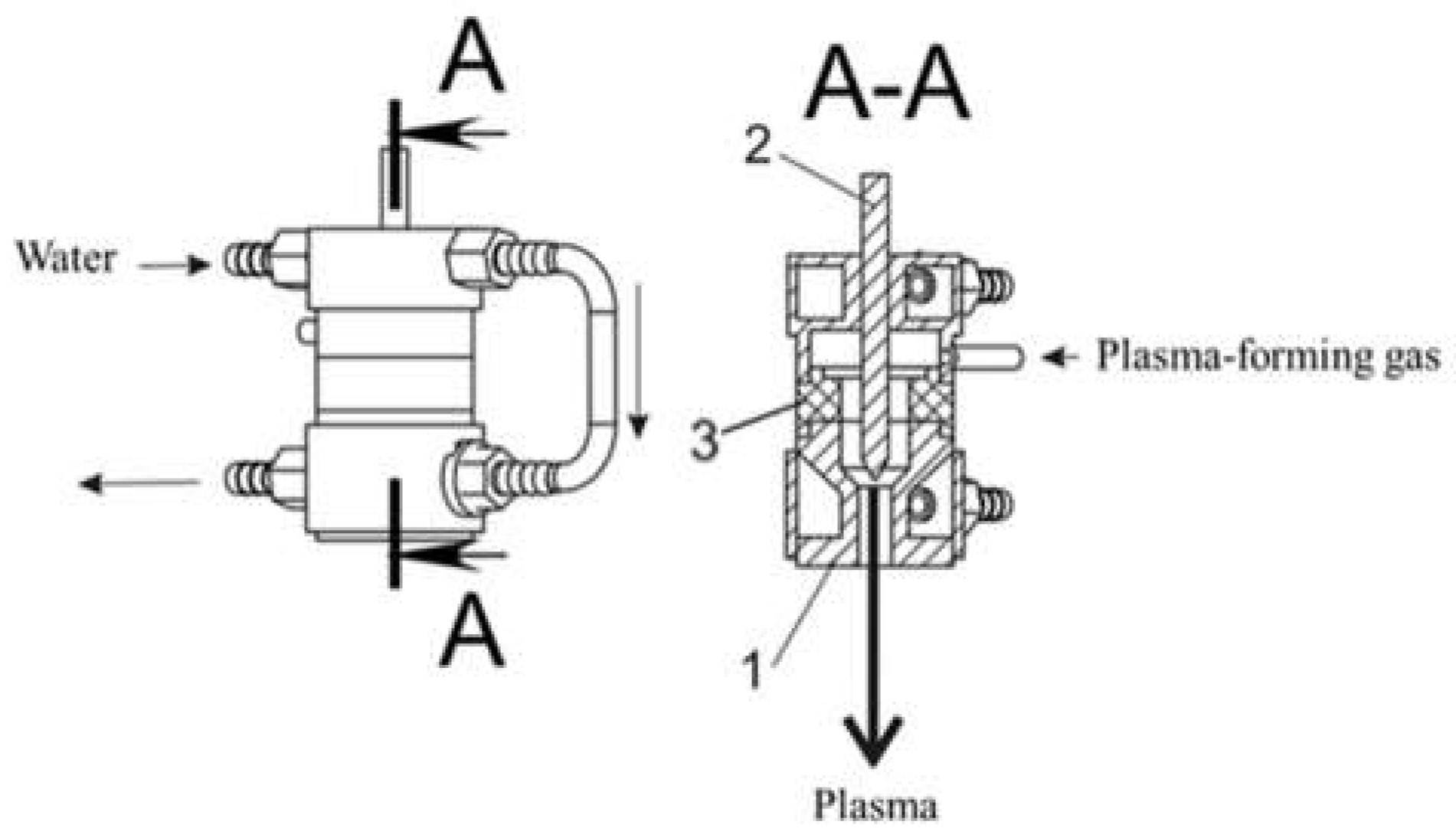
  27. Ocheredko Igor Alexandrovich, Rakhadilov Bauyrzhan Korabaevich, Tuyakbaev Bauyrzhan Toleubekovich, Kenesbekov Aidar Bakytbekuly. Plasmatron for spraying, KZ For Invention Patent No. 34334. Available online: https://kzpatents. com/?page=ipc (accessed on 29 May 2020).
  28. Kornienko, E.; Lapushkina, E.J.; I Kuzmin, V.; Vaschenko, S.P.; Gulyaev, I.; Kartaev, E.V.; Sergachev, D.S.; Kashapov, N.; Sharifullin, S.; Fayrushin, I. Air plasma sprayed coatings of self-fluxing powder materials. J. Phys. Conf. Ser. 2014, 567, 012010. [Google Scholar] [CrossRef]
  29. Doudkin, M.; Kim, A.; Kim, V. Application of fem method for modeling and strength analysis of feed elements of vibroscreen. In Proceedings of the International Conference on Computer Aided Engineering, Cairo, Egypt, 18–19 December 2018; pp. 155–162. [Google Scholar]
  30. Doudkin, M.; Kim, A.; Kim, V.; Mlynczak, M.; Kustarev, G. Computer modeling application for analysis of stress-strain state of vibroscreen feed elements by finite elements method. In Proceedings of the International Conference on Computational and Information Technologies in Science, Engineering and Education, Hong Kong, China, 14–16 June 2018; pp. 82–96. [Google Scholar]
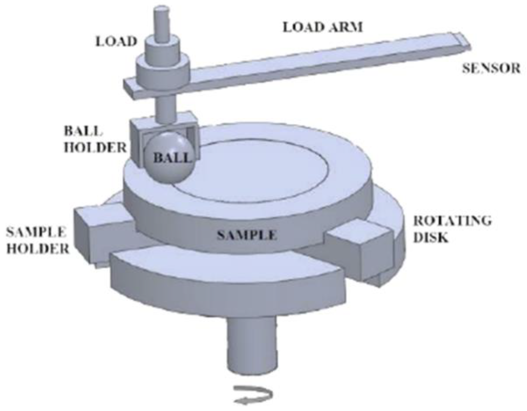
  31. American Society for Testing and Materials. ASTM G99-17: Standard Test Method for Wear Testing with a Ball-on-Disk Apparatus; ASTM: West Conshohocken, PA, USA, 2017. [Google Scholar]
  32. Beake, B.D.; Fox-Rabinovich, G.S.; Veldhuis, S.C.; Goodes, S.R. Coating optimisation for high speed machining with advanced nanomechanical test methods. Surf. Coat. Technol. 2009, 203, 1919–1925. [Google Scholar] [CrossRef]
  33. Beake, B.D. The influence of the H/E ratio on wear resistance of coating systems–Insights from small-scale testing. Surf. Coat. Technol. 2022, 442, 128272. [Google Scholar] [CrossRef]
Figure 1. Schematic diagram of a powder coating setup; 1—plasmatron, 2—anode, 3—cathode, 4—interelectrode ceramic insert, 5—tube for supplying plasma gas, 6—argon, 7—tube for supplying inert gas, 8—nitrogen, 9—sprayed powder, 10—fittings for the inlet and outlet of the coolant, 11—powder dispenser, 12—power source, 13—autonomous cooling water block.
Coatings 12 01644 g001
Figure 2. Schematic diagram of the plasmatron; 1—anode, 3—cathode, 3—interelectrode ceramic insert.
Coatings 12 01644 g002
Figure 3. Results of aerodynamic modeling of transporting gas: (a) Gradient of velocity distribution; (b) Dependence of average gas velocity on operating gas pressure.
Coatings 12 01644 g003
Figure 4. Powder particle velocity results: (a) powder particle trajectory; (b) titanium nitride particle velocity in the plasmatron.
Coatings 12 01644 g004
Figure 5. The experimental test stand for testing of samples the ball-on-disc method.
Coatings 12 01644 g005
Figure 6. Diffractograms of TiN coatings.
Coatings 12 01644 g006
Figure 7. Cross-sectional structure of coatings: (a) TiN(1); (b) TiN(2); (c) TiN(3).
Coatings 12 01644 g007
Figure 8. Adhesion strength and roughness of TiN coating.
Coatings 12 01644 g008
Figure 9. Stretch testing results of coatings: (a) TiN(1); (b) TiN(2); (c) TiN(3).
Coatings 12 01644 g009
Figure 10. Results of nanoindentation of TiN coatings obtained by the APS method.
Coatings 12 01644 g010
Figure 11. Dependence of friction coefficient of coatings on the friction path length.
Coatings 12 01644 g011
Table 1. Modes of air plasma spraying.
SampleSpraying Distance, mmAr Gas Flow Rate, L/minGas Flow Rate N, barCurrent, AProcessing Time, sThickness of Coatings, μmVoltages, V
TiN(1)15034325060~7068
TiN(2)15037335060
TiN(3)15040345060
Table 2. Results of EDS analysis of TiN coatings.
SampleSpectrumNTiFeONiCrTotal, %
TiN(1)Spectrum 110.1461.17-28.69--100.00
Spectrum 237.6563.35-27.70--100.00
Spectrum 3-63.64-36.37--100.00
Spectrum 431.5368.47----100.00
TiN(2)Spectrum 130.8967.62-1.49--100.00
Spectrum 20.8565.02-34.13--100.00
Spectrum 329.5969.14-1.27--100.00
Spectrum 4-61.79-37.21--100.00
Spectrum 5-0.671.501.408.7017.70100.00
TiN(3)Spectrum 132.1867.82----100.00
Spectrum 2-73.22-26.78--100.00
Spectrum 327.3567.821.543.29--100.00
Spectrum 428.4748.12-23.41--100.00
All results in weights %.
Publisher’s Note: MDPI stays neutral with regard to jurisdictional claims in published maps and institutional affiliations.

