Abstract
Cyclic loading tests were conducted for eight composite joints (five interior joints and three exterior joints) with steel reinforced recycled concrete (SRRC) columns and steel beams under cyclic loading. The axial compression ratio and recycled coarse aggregate (RCA) replacement percentage were considered as the main design parameters for the above composite joints. The seismic behavior of the composite frame joints with (SRRC) columns and steel beams were studied by numerical simulation and the constitutive models of recycled aggregate concrete (RAC), steel and reinforcement were given to the corresponding elements. The experimental results were used to validate the finite element (FE) model. The results indicated that the FE model can accurately predict the deformation and stress load-strain curves of the composite joints. Then, a FE parameter analysis was carried out on the seismic behavior of the composite joints. The RAC strength, steel strength and column steel web thickness were considered as the main parameters. Results pinpointed that the increase in RAC strength and steel web thickness of the columns significantly affected the horizontal bearing capacity of the composite joints. However, with the increase in RAC and steel strength, the deformation ability and ductility of composite joints were almost unaffected. The reasonable increase in column steel web thickness can improve the seismic ductility of composite joints, evidently. On this basis, considering the stress characteristics of joint specimens, a four broken line restoring force model for steel reinforced recycled concrete column steel beam composite frame joints was established. This model includes the skeleton curve model, the stiffness degradation pattern and hysteresis rules. The calculation curve was in good agreement with experimental curves, which can well reflect the hysteretic behavior of joints subjected to low cyclic repeated loading. The above results can be used as a reference for the seismic design of composite frame joints.
1. Introduction
With the acceleration of urbanization, a large amount of concrete demand leads to long-term over-exploitation of natural sand and stone materials, resulting in huge energy and natural resource consumption, and at the same time, the demolition of old buildings, new building construction and other human activities generated by the building waste accumulation. In addition, various natural disasters cause a large number of buildings to collapse and become damaged, and produce a large amount of construction waste, which seriously hinders the sustainable development strategy of the ecological environment, and bring serious problems to society, the economy and the ecological environment. Therefore, it is of great scientific significance and application value to develop a new type of structure system with good seismic performance and ecological environment friendliness. The emergence of recycled concrete can effectively solve the above problems [1]. It can reprocess waste concrete, recover its original mechanical properties to the greatest extent and form new building materials. This technology can not only reuse limited resources, but also solves some environmental problems. The promotion and application of recycled concrete technology can transform the traditional concrete production mode into the track of sustainable development.
The section steel recycled concrete column is a kind of combination form, a new type of composite member formed by configuring section steel, matching certain structural longitudinal bars and stirrups and, finally, by pouring recycled concrete. In steel structures, steel beams have good flexural performance. Compared with concrete beams, steel beams are lighter and can effectively reduce the section size of members, thus increasing the use space of the structure. In view of this, and in view of the characteristics of steel recycled concrete columns with good seismic performance and high bearing capacity, combined with the advantages of steel beams with good mechanical properties and simple construction, this paper puts forward a new structure system, the composite frame structure of steel recycled concrete columns and steel beams (SRRC). Numerous studies have been conducted on the performance of recycled aggregate concrete (RAC), including its preparation methods, physical and mechanical properties, durability, fatigue and bonding properties [2,3,4]. Ma et al. conducted experimental research and a theoretical analysis of RAC member sand structures [5,6,7,8,9]. Their results showed that the mechanical properties of RAC and its structures are inferior to those of ordinary concrete. This nature of RAC limits its engineering application, particularly in seismic structures, to a certain extent. Considering the good mechanical properties of steel and concrete composite structures, several scholars have attempted to apply RAC to composite structures to improve the mechanical properties of RAC structures and structural members. SRRC structures are among these steel and RAC composite structures [10,11,12]. In previous studies, SRRC columns that were tested under cyclic loading presented good seismic performance and high bearing capacity, and the results significantly promoted the application of RAC. As a new type of composite structure system, the restoring force model of the composite joints of SRRC was the basis for the analysis of the elastoplastic time history of the structure. The restoring force model should fully reflect the mechanical properties of the structure or component, such as strength decay, stiffness degradation, deformation ductility, energy dissipation capacity, damage evolution and so on, which was an important basis for the seismic performance analysis of the structure. The actual restoring force characteristic curve was very complex, so it was difficult to apply it directly to the analysis of the elastic–plastic seismic response of the structures. In order to facilitate the mathematical description and engineering application, the restoring force characteristic curve obtained by the test was abstracted and simplified in the form of mathematical modeling, and then the restoring force model of the structure or component was obtained. The research on the restoring force characteristics of SRRC was not mature. Only Xue et al. discussed the restoring force model of such joints under plane stress [13,14]. There is still a lack of research results on the restoring force model of SRRC.
Accordingly, the seismic performance of the composite joints has been further studied by the finite element method. The validity and accuracy of the refined numerical model were verified through experimental data. In addition, the influence of design parameters on the mechanical performance of composite joints was also investigated. On this basis, considering the failure process of the joints, a four-fold skeleton curve model of the composite joints was established by the regression fitting method. Moreover, through analyzing the stiffness degradation law and hysteretic rule in the whole loading and unloading process, a hysteretic curve restoring force model of the composite joint was proposed, which can provide reference for the engineering application of the joint.
2. Axial Compression Tests of the Composite Joints
2.1. Research Significance
The preparation and use of a large number of concrete materials lead to the long-term over-exploitation of natural sand and stone materials, resulting in huge energy and resource consumption. At the same time, the construction waste generated by the demolition of old buildings, new buildings and other human activities has piled up. In addition, earthquakes, tsunamis and floods and other natural disasters caused a large number of building collapses, a large amount of construction waste, etc., which to the sustainable development of our country has brought more and more serious social, economic, ecological and environmental problems. At present, construction waste is generally treated by stacking and burying, and its comprehensive utilization rate is too low. From the above, we can see that, on the one hand, it is the over-exploitation of natural non-renewable resources such as sand and stone. On the other hand, a large amount of construction waste in the natural and ecological environment is caused by serious pollution. Therefore, how to deal with and utilize these large amounts of construction wastes reasonably and effectively, so as to realize the resource-saving and environment-friendly society and the sustainable development of the economy, has become one of the problems that governments of all countries must face and solve. In view of the good seismic performance and high bearing capacity of the steel recycled concrete column, and the advantages of the steel beam, such as good mechanical performance, being light weight, of easy construction and being effective in the reduction of the section size of the members, a new structure, the composite structure of the steel recycled concrete column and steel beam, was proposed. Compared to traditional reinforced concrete structures and steel structures, the combination structure not only has high carrying capacity, good seismic performance, good durability and fire resistance, saves steel and other advantages, but also has the remarkable characteristics of renewable concrete environmental protection, and meets the requirements of our sustainable development; therefore, it has broad application prospects for development.
2.2. Design and Production of Specimens
The low cyclic loading test and shear strength of composite joints with SRRC columns and steel beams were studied in detail by the authors [15]. Eight joints were designed, including five interior joints and three exterior joints. The effects of the recycled coarse aggregate (RCA) replacement ratio and axial compression ratio on the seismic performance of the composite joints were mainly considered [16]. The design parameters of the composite joints are shown in Table 1. The details of the size and reinforcement of composite joints are presented in Figure 1. The composite joints production and completion process is shown in Figure 2. The mix of RAC materials is demonstrated in Table 2. The design parameters of each joint are shown in Table 3.

Table 1.
Design parameters of specimens.
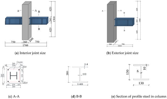
Figure 1.
Size and distributed steel of specimens (mm).
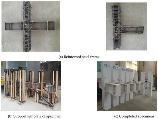
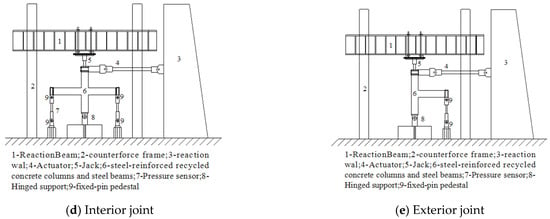
Figure 2.
Schematic diagram of main manufacturing process and test device of test piece.

Table 2.
Mix ratio of RAC materials.

Table 3.
Design parameters of joint specimens.
2.3. Failure Modes of Specimens
From the experimental results, the typical shear failure of each composite joint occurs under low cyclic load. There were obvious shear deformation and “X” shaped cross-diagonal cracks that appeared in the joint core region. From the influence of the two designed parameters on the cracking load of joints, the RCA replacement rate has little effect, while the axial compression ratio has a great influence on the cracking of joint core region. The cracking load of joints with different RCA replacement rates was approximately 70 kN, and there was no significant difference in the crack development process and distribution characteristics. The cracking load of joints with a large axial compression ratio was significantly greater than that of joints with a small axial compression ratio. The failure characteristics of CFJ1–CFJ8 are recorded in Figure 3.
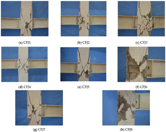
Figure 3.
Failure modes of joints.
2.4. Comparison with Previous Studies
In order to verify the accuracy of the test and the correctness of the results, the following conclusions are drawn by comparing the experimental results and analysis in the previous literature:
- (1)
- The failure modes of the joints in the reinforced steel recycled concrete frame are similar to those of the ordinary reinforced steel concrete frame, both of which are shear failure in the core area of the joints, and the shear deformation in the core area is significant [17].
- (2)
- The failure modes of the specimens under repeated cyclic loads were the same, and obvious “X”-shaped cross-oblique cracks were formed along the diagonal. The failure modes are shear baroclinic failure, flexural shear failure and bending failure. However, due to the different structures of the specimens, the results can only serve as a reference [18].
- (3)
- The hysteretic curves of the joints of the recycled steel concrete frame are roughly spindle-shaped, which are similar to the hysteretic curves obtained in the references, and the mechanical properties are in line with the mechanical properties of the steel frame and reinforced concrete frame [19].
3. Model Descriptions of the Composite Joints
3.1. Constitutive Models of the Materials in the Joints
(1) Constitutive relationship of steel
ABAQUS software 6.16 (Dassault Systèmes, Vélizy-Villacoublay, France) enables a variety of constitutive models for steel materials. At present, the widely used constitutive models include elastic–plastic, whole curve, bilinear and three-fold line models. The steel used in the test was Q235 low carbon steel, which belongs to the isotropic elastic–plastic material with an obvious yield point. The stress-strain curve generally adopts a simplified secondary plastic flow model. This model encapsulated that the longitudinal stress of the steel directly enters the strengthening stage after reaching the yield stress, while the strength of the plastic flow stage was unchanged. The secondary plastic flow model can not only consider the strengthening effect of steel, but also reflects the real material characteristics. The stress-strain curve of steel is shown in Figure 4. The mathematical expression of the stress-strain is determined by Equation (1):
where σi is equivalent stress of steel, fs is the yield strength of steel, fu is the ultimate strength of steel, Es is elastic modulus of steel, Et is the tangent modulus of steel, ζ is the strengthening coefficient ζ = 1/216, εi is equivalent strain of steel, εy is the strain of steel at yield, εu is the strain at the limit of steel, εst = 12εy, εu = 120εy.
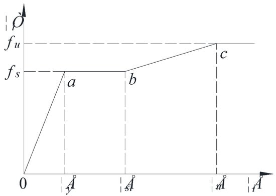
Figure 4.
Stress-strain curve of steel.
The Poisson’s ratio of steel is assumed to be:
The above steels all adopt Miss yield criterion, which is defined as a relatively general yield criterion. In a 3D space, the Miss yield surface is a cylindrical surface with σ1 = σ2 = σ3 as the axis. On a 2D plane, the yield surface is an ellipse. Any stress state inside the yield surface is elastic, and any stress state outside the yield surface will cause yield. Miss yield criterion is suitable for materials with good toughness.
The spatial representation of Miss yield criterion is shown in Figure 5. The mathematical expression of equivalent stress is:
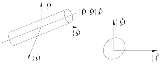
Figure 5.
Schematic diagram of Miss yield criterion.
In the formula: σ1, σ2, σ3 are three principal stresses.
(2) Hysteretic curve model of reinforcement
Existing studies have stated that the direct manifestation of the bond-slip between concrete and reinforcement in structural hysteretic curve analysis is the emergence of the “kneading” phenomenon. As a result, how to accurately describe the kneading phenomenon is one of the difficulties in numerical analysis. After comparison with the VECCHIO model of reference [20], the M-P model of reference and hysteretic curve model of the reference based on CLOUGH frame [21,22], Professor Zihu Fang of Shenzhen University established a hysteretic model of reinforcement that considered the bond-slip effect [23,24]. In this paper, the steel model was selected to simulate the hysteretic behavior of composite joints. The model is described in Figure 6.
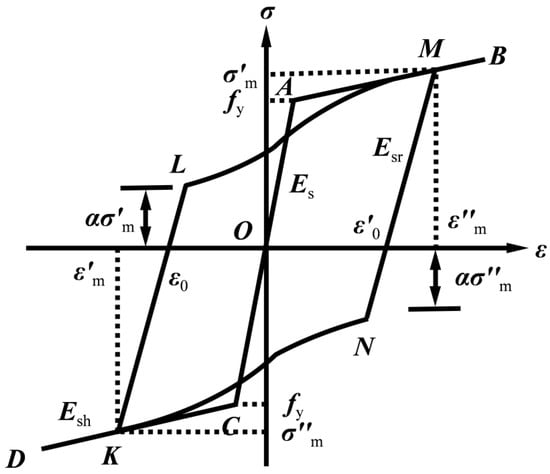
Figure 6.
Present hysteretic model of bar.
(3) RAC material
The RAC was mainly distributed in the column, while the SRRC column was mainly composed of RAC, reinforcement and section steel. Therefore, the RAC part will be subject to different forms of constraints, which can be roughly divided into the section steel constraint part and reinforcement constraint part. The strength of the two constraints on RAC was different, so the reinforcement constraint area was called the weak constraint area, and the section steel constraint area was called the strong constraint area [25]. Figure 7 shows the distribution details of the SRRC column section constraint areas. For the convenience of the model, referring to the simplified method of Ellobody [26], the arc region in Figure 7 is simpiflied as a straight line. Based on this linear division method, the section constraint area of the SRRC column was divided as shown in Figure 8. The stress-strain curves of different concrete areas are presented in Figure 9.
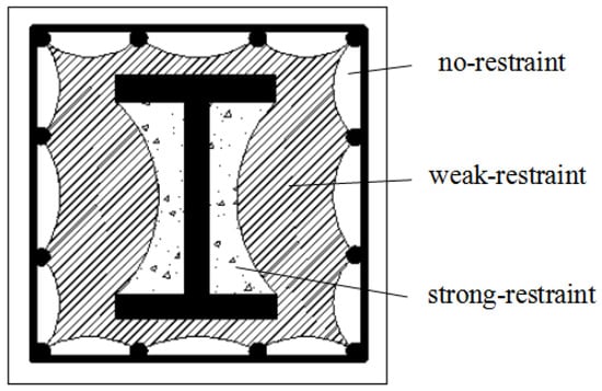
Figure 7.
Section divisions of composite column.
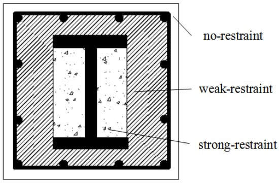
Figure 8.
Regions simplified for composite sections.
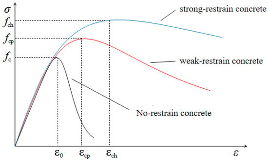
Figure 9.
Stress-strain curves for concrete.
fc is the axial compressive strength of RAC and ε0 is the peak strain of RAC; fcp is the peak stress of concrete in the weak constraint area and εcp is the peak strain of concrete in the weak constraint area; fch is the peak stress of strong constraint concrete and εch is the peak strain of strong constraint concrete.
3.2. Definition of Concrete Damage
The plastic damage model is provided in the simulation of the concrete reciprocating load. Under the reciprocated load, the damage index of the concrete model gained a significant impact on the simulation results [27]. In order to improve the accuracy of ABAQUS in a nonlinear calculation, domestic and foreign scholars have included the damage of concrete in the FE simulation [28,29,30]. At present, there are many damage models for concrete. The damage factor was calculated by the Mander method. The formula was stated as follows:
Determined peak strain εcc and reverse unloading point (εun, σun) of concrete are the key to solving the damage factor by the Mander method.
The yield function and plastic potential function of materials are the critical factors affecting the performance of RAC. This paper uses meridian plane (p, q) and partial plane (q, θ) to represent it. The yield condition criterion is scheduled as follows:
Figure 10 and Figure 11 show the plane stress yield surface and the stress yield surface on the deviatoric plane of the concrete plastic damage model.
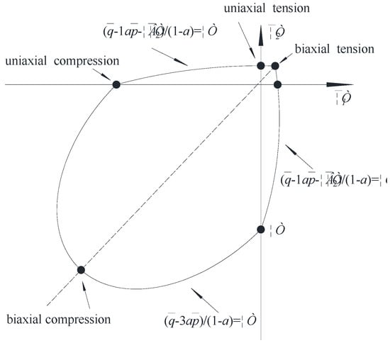
Figure 10.
Yield surface in plane stress state.
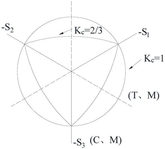
Figure 11.
Yield surface in deviatoric stress state.
3.3. Interaction between the Materials
The steel reinforced part was embedded into the concrete through the embedded function in ABAQUS. There were no anti-sliding structural measures such as studs between the steel and RAC. Consequently, it was necessary to define the interaction between steel reinforced and RAC. Kinematic contact was selected for the normal direction contact of the two contact surfaces, which was also called “hard” contact. In other words, in addition to mutual contact, there was no interaction force between the surfaces as separation after contact was allowed. The Coulomb friction model was adopted for the bond-slip in the tangential direction, while the friction coefficient was set to 0.25 according to the research results [31,32].
3.4. Description of Mesh and Elements
The type of C3D8R element was adopted in the steel beam, built-in column steel and RAC, which was an eight-node hexahedron reduction integral solid element. Element type T3D2 was applied for the longitudinal reinforcement and stirrup in the composite column and the double-node three-dimensional truss element. The mesh size was 50 mm × 50 mm. The mixed model of these two element types not only improves the calculation accuracy, but also ensures the calculation speed to some extent. Figure 12 describes the FE model of the composite joints element mesh.
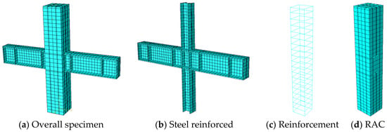
Figure 12.
Mesh division of composite joints.
3.5. Axial Loading Method and Boundary Conditions
The overall FE model was modeled according to the size of the test. The boundary conditions of the model were consistent with the load conditions of the actual test. The horizontal reciprocated load and axial force were applied on the top of the column. The beam end was connected by connected rods, and the bottom of the column was hinged. The hybrid loaded method of force and displacement was adopted in the test. However, considering that it was easier to ensure calculation convergence by using displacement control in FE simulation, displacement control was used to replace the mixed control in FE simulation. Finally, the Newton iteration method was conducted to calculate the FE model.
4. Verification of FE Model on the Composite Joints
4.1. Comparative Analysis of Experimental Results and Simulation Results
Through the modeling calculation of CFJ1–CFJ8 composite joints, the load-displacement hysteretic curves and skeleton curve of each composite joint were obtained. The comparison between the test results and the FE simulation results is shown in Figure 13 and Figure 14. For the skeleton curve, it is the track of the maximum peak value of horizontal force reached by each cyclic loading that reflects the different stages of force and deformation of components and their characteristics (strength, stiffness, ductility, energy dissipation and collapse resistance, etc.), and it is also an important basis for determining the characteristic points in the restoring force model.
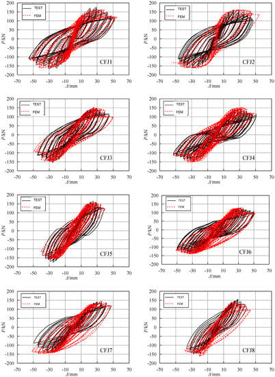
Figure 13.
Comparison of test and simulation results of hysteretic curves of composite joints.
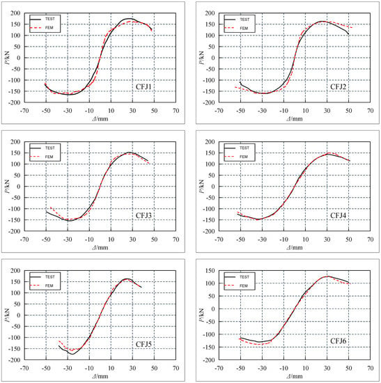

Figure 14.
Comparison of test and simulation results of skeleton curves of composite joints.
The hysteretic curves in Figure 13 and the skeleton curves in Figure 14 pinpoint that the simulation results of the hysteretic characteristics of the composite joints are basically in good agreement with the experimental results. However, compared with the experimental curves, the pinch effect of the simulated hysteretic curve of the exterior joints (CFJ6–CFJ8) is far from expectation. The unloading stiffness of the simulated curve is relatively larger. The main reason may be that the exterior joints are asymmetric structures. In addition, the cumulative damage of positive loading is greater than that of negative loading in the simulation. When the cumulative damage of positive loading reaches a certain degree, the damage degree of continuous loading to the positive is greater than that of negative loading. As a result, the unloading stiffness of the simulated curve is larger. This phenomenon is also reflected in the skeleton curves of the exterior joints. The stiffness of the simulated curves under negative loading is slightly larger than that of the experimental curves. In general, the numerical simulation is in good agreement with the experimental results, which verifies the availability and correctness of the numerical simulation method, and can be used as a reliable numerical method for further analysis in the following paragraphs.
4.2. Comparison of the Characteristic Values of the Composite Joints
Table 4 presents a comparative analysis on the load and corresponding displacement values of the composite joints obtained by numerical simulation and test at each characteristic point. It indicates that the load error of each characteristic point is basically within 6%, indicating that the bearing capacity consistency is fine, but some displacement differences are relatively large. The reasons may be as follows. First, there was a gap between each test equipment in the real test, resulting in a certain assembly error. Second, the bond-slip between steel bar, section steel and RAC in FE simulation was analyzed under the ideal condition, but in fact, the bond-slip of each part was quite complicated during the test process. Therefore, there is a certain difference in the bond-slip between the FE simulation and the real test. On the whole, there are some differences between the numerical analysis and the test results, but they are also within the acceptable range. It shows that the FE simulation results possess good accuracy.

Table 4.
Comparison of test and simulation results of bearing capacities and displacements.
4.3. Deformation and Stress Characteristics
The deformation characteristics and failure modes of all composite joints obtained by FE analysis are basically consistent with the test results. Therefore, in order to avoid repeated statements, the results of interior joint CFJ5 and exterior joint CFJ7 are representative and typical, which are exhibited in Figure 15 and Figure 16.
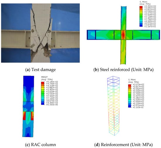
Figure 15.
Comparison of test and simulation results of CFJ5.
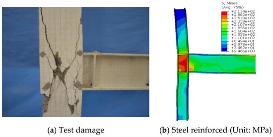
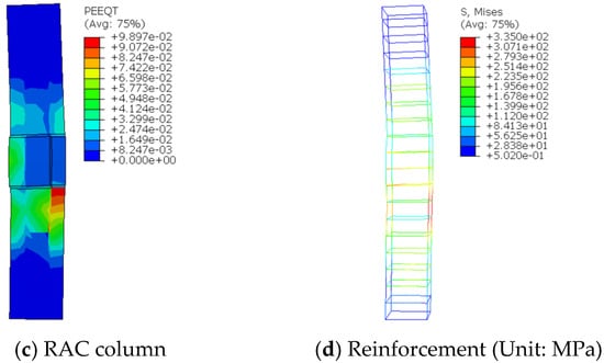
Figure 16.
Comparison of test and simulation results of CFJ7.
In ABAQUS, the damage of concrete is mainly checked by two indicators: compression equivalent plastic strain (PEEQ) and tension equivalent plastic strain (PEEQT). Therefore, PEEQT was used to reflect the failure of RAC. Figure 15 and Figure 16 inform that when the joint was under ultimate load, the RAC in the core area of the joint formed a banded compression zone, which roughly formed oblique cracks along the diagonal direction. The compression mechanism of the oblique compression rod of the composite joint was consistent with the “X” shape diagonal cracks produced in the core area of the joint in the test. Figure 15 and Figure 16 demonstrate the Mises stress diagrams of the steel reinforced and reinforcement cage of the composite joint model under ultimate load. It can be concluded that the yield of the steel web in the core area of the joint was gradually expanded from the middle local area to the outside. When the steel web was yielded in the core area of the joint, there was no plastic hinge at the end of the steel beam and column. It showed that the damage area mainly occurred in the core area of the joint, which was consistent with the experimental failure process. In summary, the FE model established can accurately reflect the stress of the composite joint, which can be applied to subsequent parameter analyses.
5. Parametric Analysis of FE on the Composite Joints
Due to the limitations of test conditions, financial and human resources, it is not practical and economical to carry out experimental research on each parameter affecting seismic performance. Moreover, the influence of other parameters on the seismic performance of the composite joints needs to be investigated further. Therefore, the influence of other parameters on the seismic performance of the composite joints was analyzed by ABAQUS 6.16 software in this paper.
From the load displacement skeleton curve in the above model verification, it can be concluded that the skeleton curve of the joint can reflect the full stress process of the composite joint in detail. Therefore, considering the calculation efficiency in FE parameter analysis, the pushover analysis was carried out with the interior joint as the basic specimen. The RAC strength, yield strength of section steel and web thickness of column steel web are the main analytical parameters.
5.1. RAC Strength
When including the influence of RAC strength factors, only changing this single parameter in numerical analysis leads to other parameters remaining unchanged. The RAC strength fcu was 35 MPa, 45 MPa, 55 MPa and 65 MPa. The numerical simulation results are shown in Figure 17. Table 5 lists the influence of RAC strength on each characteristic point of the composite joints.
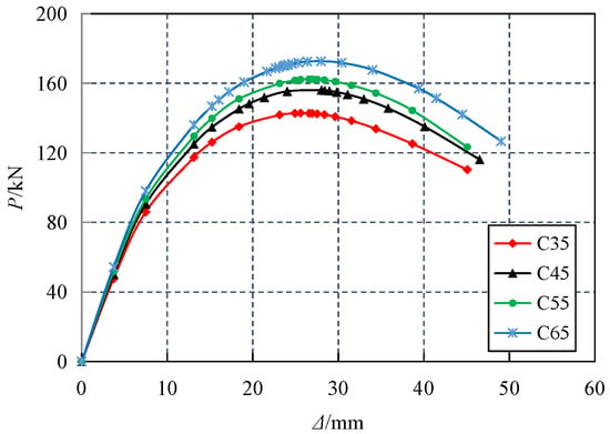
Figure 17.
Influence of RAC strength on composite joints.

Table 5.
Influence of RAC strength on characteristic points of composite joints.
It can be estimated from Figure 17 and Table 5 that the strength of RAC has little effect on the initial stiffness of the composite joint. The horizontal bearing capacity of the composite joints increased with the increase the strength of RAC, while the maximum increase was 20.87% compared with the peak bearing capacity of the composite joints with strength grade C35, which indicated that the increase of the strength of RAC can significantly improve the strength of the composite joint. The displacement corresponding to the peak load was similar, indicating that the strength of RAC has little effect on the deformation capacity of the composite joints. At the end of loading, the horizontal load also gradually increased with the increase of RAC strength, and the skeleton curve had a significant decline. The ultimate load of each specimen decreased by 22.75%, 25.60%, 24.01% and 26.64% relative to the peak load.
5.2. Yield Strength of Steel
Steel accounts for a large proportion of composite joints. The influence of steel strength on joints cannot be ignored. Therefore, Q235, Q345, Q390 and Q420 steels commonly applied in practical engineering were selected as the influence parameters of numerical simulation. The numerical simulation results were recorded in Figure 18, and the influence of yield strength of different types of steel on each characteristic point of composite joint is listed in Table 6.
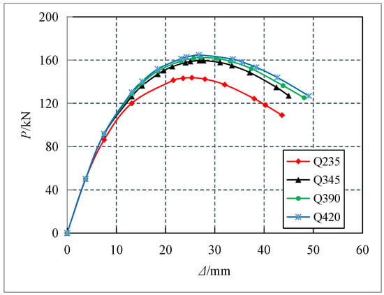
Figure 18.
Influence of yield strength of profile steel on composite joints.

Table 6.
Influence of yield strength of profile steel on characteristic points of composite joints.
It can be seen from Figure 18 and Table 6 that the horizontal bearing capacity of the composite joints increases slightly with the increase of steel yield strength. Compared with the Q235 steel composite joint, the peak bearing capacity of the Q345, Q390 and Q420 steel composite joints was increased by 11.04%, 13.02% and 14.57%, respectively. However, there was little difference among them. The displacements of the joints with different strengths were similar, indicating that the yield strength of steel has little influence on the deformation capacity of the composite joints. The skeleton curves of the strength joints of all types of steel were significantly reduced. The ultimate load of the combined joints is 24.11%, 20.39%, 22.91% and 22.94% lower than the peak load. It can be seen that the deterioration of the composite joints was basically gentle, demonstrating that the yield strength of steel had little effect on the ductility of the joints, and showed good ductility in general.
5.3. Thickness of Column Steel Web
In order to study the influence of different column steel web thicknesses on the performance of composite joints, this paper took d = 4~10 mm for the parameter influence analysis, and d was taken as 4 mm, 6 mm, 8 mm and 10 mm. The numerical simulation results are shown in Figure 19. Table 7 lists the influence of column steel web thickness on each characteristic point of the composite joints.
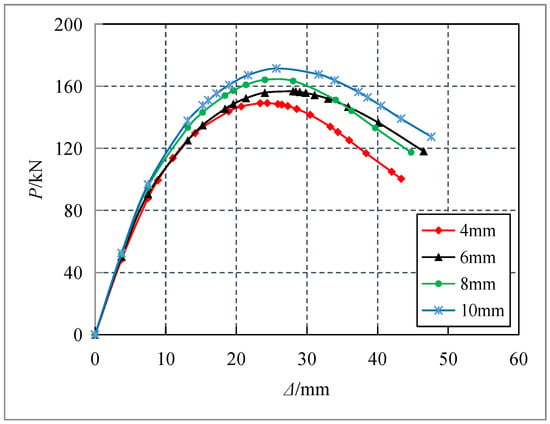
Figure 19.
Influence of profile web thickness on composite joints.

Table 7.
Influence of profile web thickness on characteristic points of composite joints.
It can be estimated from Figure 19 and Table 7 that the column steel web has little effect on the stiffness of the initial elastic section of this type of composite joints, but has great influence on the peak bearing capacity and the degradation of the later bearing capacity. Compared with the peak bearing capacity of the composite joints with 4 mm web thickness, the peak bearing capacity of the composite joints with 6 mm, 8 mm and 10 mm web thicknesses increased by 5.13%, 10.04% and 14.93%, respectively, demonstrating that the thickness of column steel web had a significant effect on improving the strength of the composite joints. At the end of loading, the ultimate horizontal bearing capacity of the column increases with the increase of the steel web thickness, but the decline section of the skeleton curve was still obvious and the decline trend was similar. In summary, the increase of column steel web thickness can improve the horizontal bearing capacity of composite joints, while reasonable web thickness can also improve the seismic ductility of composite joints.
6. Restoring Force Model of Composite Joints
6.1. Establishing Method
The principal stress process and characteristics of composite joints were analyzed by low-cycle cyclic loading tests on the inner and outer joints of composite joints under different RAC replacement rates and axial compression ratios. Combined with the test hysteretic curve and skeleton curve, the restoring force model of interior joints and exterior joints in the composite joints was proposed by using the fitting method of test data, which provided reference for the elastic–plastic seismic response analysis of the composite joints and frame.
The following assumptions are mainly the simplification and summary of the principal stress process and characteristics of composite joints, the experimental hysteretic curves and skeleton curves. They should be made first before established the restoring force model of composite joints with SRRC columns and steel beams.
- (1)
- Assume that the elastic limit point of the specimen coincides with the cracking point of the composite joints;
- (2)
- Before the cracking point, the unloading stiffness and loading stiffness of the composite joints were the same, and after the elastic section, the stiffness decreased with the increase of displacement;
- (3)
- The skeleton curve adopted elastic stage, crack working stage, yield strengthening stage and failure stage four-fold line model.
6.2. Establishment of Skeleton Curve Model
The skeleton curve obtained by the actual test was a continuous smooth curve without an obvious yield point. When established the restoring force model of skeleton curve, it should be simplified to a quadrangle model with stiffness degradation. The details are stated as follows:
The characteristic points of skeleton curve were cracking point A (Pc, Δc); yield load point B (Py, Δy); peak load point C (Pmax, Δmax); and limit load point D (Pu, Δu), where yield load point B was calculated by the “general yield moment method”, and limit load point D was 85% of the peak load. Due to the differences of skeleton curves of various composite joints, dimensionless processing was carried out for skeleton curves of various composite joints first, as shown in Figure 20.
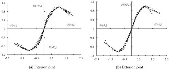
Figure 20.
Dimensionless skeleton curve.
It can be estimated from Figure 20 that the data points of the skeleton curve of interior joints and exterior joints after dimensionless processing have good regularity, as shown in the real line in the graph. The linear regression method was applied to fit the data points of each stage of the skeleton curve. The four-line skeleton curve model was shown in Figure 21. OA was the elastic section from the positive loading to the cracking point, while AB was the working section with cracks under positive loading, and BC was the yield strengthening stage under positive loading, while CD was the failure stage under positive loading. OA’ was the elastic section from reverse loading to cracking point, AB was the working section with cracks under reverse loading, B’C’ was the yield strengthening stage under reverse loading and C’D’ was the failure stage under reverse loading. The fitting process of skeleton curves of interior joints and exterior joints in each stage is exhibited in Figure 22. The linear equations and stiffness in each stage of the skeleton curve model are shown in Table 8 and Table 9.
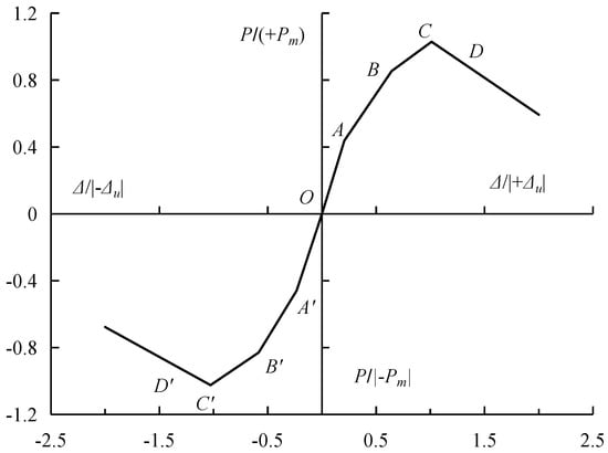
Figure 21.
Skeleton curve model with four-line.
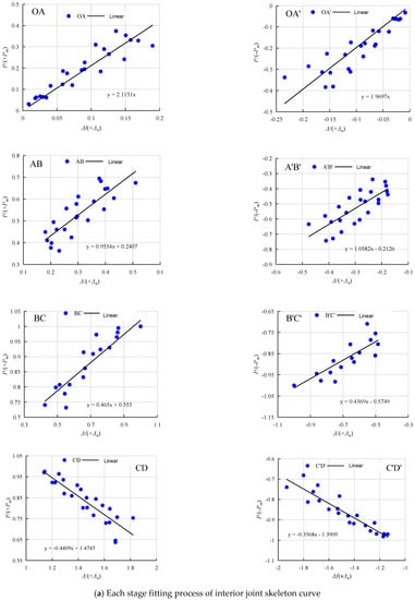
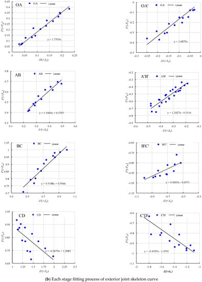
Figure 22.
Fitting process of skeleton curve.

Table 8.
Linear equation and stiffness of each stage in skeleton curve model of interior joint.

Table 9.
Linear equation and stiffness of each stage in skeleton curve model of exterior joint.
6.3. Stiffness Degradation Rule
Through the low-cyclic loading test of composite joints, it was found that the stiffness of the composite joints decreases gradually with the increase of load and displacement loading stages. The skeleton curve restoring force model simplifies the whole loading process of the composite joints into four stages, and nonlinear fitting was carried out for the loading stiffness and unloading of the composite joints at each stage. The variation of the forward and reverse unloading stiffness of the composite joints was described in detail below. K12, K34 and K56 represent the unloading stiffness under forward loading, while K1′2′, K3′4′ and K5′6′ represent the unloading stiffness under reverse loading, as presented in Figure 23.
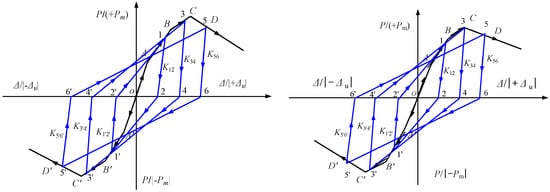
Figure 23.
Stiffness degradation rule of specimen.
The unloading stiffness K12, AB section was the working stage of positive loading with cracks. When unloading before positive loading to A, the unloading route was along OA, and the unloading stiffness was the initial stiffness K0 of the composite joints. After the unloading of section AB, the unloading route was carried out along 12, and the unloading stiffness was K12. The slope K12 of forward unloading route 12 was obtained by linear fitting and all measured data between unloading point 1 and point 2 when unloading load was 0. Then, the unloading stiffness of the AB section of each composite joint was normalized, while the nonlinear regression fitting was carried out by power function. The nonlinear relationship curve between K12/K0 and Δ1/(+Δm) was obtained, where K0 was the initial stiffness of the positive loading elastic section, or the slope of the straight line obtained by linear fitting of the measured data of the positive loading elastic section of the skeleton curve. Δ1 was the displacement corresponding to positive loading point 1. The above method was adopted to nondimensionalize the unloading stiffness of each test. Moreover, the power function was used for nonlinear regression fitting, as shown in Figure 24.
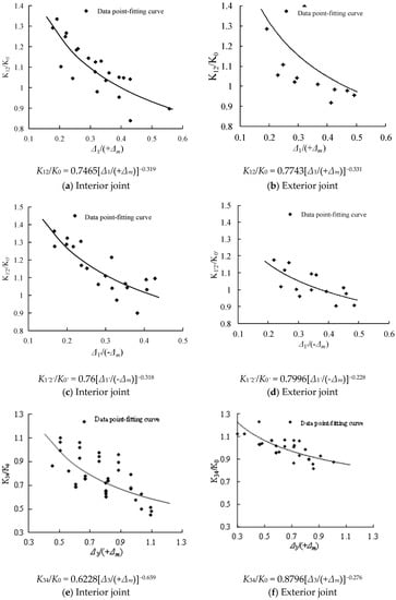
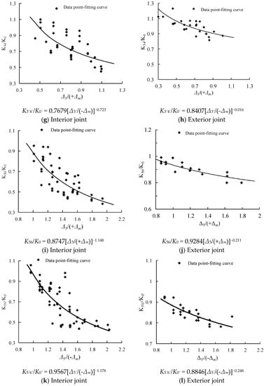
Figure 24.
Stiffness degradation rule curve of unloading stiffness.
Based on the experimental research, combined with the obtained hysteretic curve and skeleton curve, the restoring force model of composite joints proposed was shown in Figure 25. The model considered the four stress stages of the composite joints during the whole loading process in the form of four broken lines, and fitted the stiffness degradation law of each stage, which can truly reflect the stiffness degradation law of the composite joints in each stress stage and was suitable for the elastic–plastic analysis of composite joints and other structures.
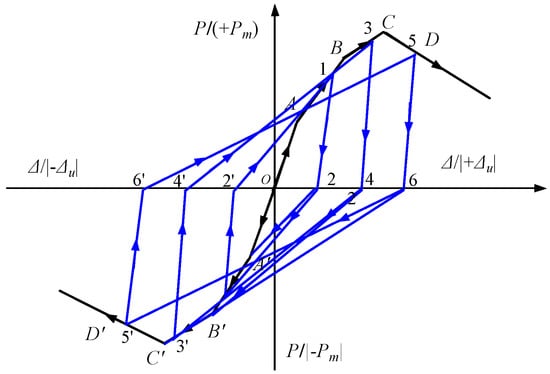
Figure 25.
Four-line restoring force model of stiffness degradation.
The restoring force model was described as follows:
- (1)
- The restoring force model was obtained by combining the main feature points (cracking point, yield point, peak point and limit point) of the test skeleton curve and by dimensionless processing and fitting of the test data. The coordinates were dimensionless coordinates.
- (2)
- The skeleton curve of the restoring force model was divided into four stages. In the figure, OA and OA′ were elastic sections under positive and negative loading, respectively, AB and A′B′ were working sections with cracks under positive and negative loading, respectively and BC and B′C′ were yield strengthening sections under positive and negative loading, respectively, while CD and C′D′ were failure sections under positive and negative loading, respectively.
- (3)
- When the specimen is loaded and unloaded in the elastic segment (OA and OA′), the unloading stiffness was the elastic stiffness of the specimen. When the specimen was loaded to the elastic segment (AD and A′D′), the unloading stiffness gradually degrades.
Therefore, the restoring force model established in this paper mainly has the following characteristics. In the quasi-static test, the loading and unloading stiffness of the composite joints before reaching the cracking load were both initial stiffness. After reaching the cracking load, the stiffness degradation phenomenon of the composite joints is considered. After cracking, the stiffness of forward and reverse loading gradually degrades with the increase of displacement, and the degradation rate accelerates with the loading process.
6.4. Validation of Restoring Force Model
According to the regression equations of the skeleton curve model at each stage shown in Table 8, the established skeleton curve model was compared with the experimental skeleton curve, as exhibited in Figure 26.
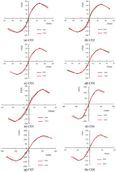
Figure 26.
Comparison of skeleton curve between calculation results and test results.
The calculated hysteretic curve of each composite joint can be acquired by the four-fold restoring force model proposed in Figure 20. The calculated hysteretic curve was compared with the experimental hysteretic curve, such as Figure 27.
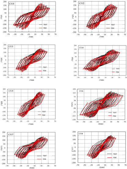
Figure 27.
Comparison of hysteretic curve between calculation results and test results.
From Figure 26 and Figure 27, it can be seen that the skeleton curve and hysteretic curve calculated by both interior joints and exterior joints were in good agreement with the overall trend of the test skeleton curve and hysteretic curve. The results demonstrated that the four-fold restoring force model proposed can well reflect the hysteretic characteristics of composite joints with SRRC columns and steel beams under low cyclic loading.
7. Results of the Study
7.1. Conclusions
Based on the experimental study, the failure mechanism of composite joints with SRRC columns and steel beams is studied, the mechanical model is established and the calculation method of bearing capacity is verified. The refined numerical model of composite joints with SRRC columns and steel beams was established, and the design parameters were extended and analyzed. The main conclusions are as follows:
- (1)
- The finite element calculation results are in good agreement with the experimental results, which shows that the simulation method in this paper has good rationality and applicability. The modeling method can provide a reference for the numerical analysis of these kind of joints.
- (2)
- With the increase of RAC strength, the horizontal bearing capacity of the composite joints increases significantly, but the stiffness of the elastic section increases slightly, and the RAC strength has little effect on the deformation capacity of composite joints.
- (3)
- The increase of steel yield strength has no obvious effect on the horizontal bearing capacity and ductility of the composite joints.
- (4)
- The increase of the thickness of column steel web can improve the horizontal bearing capacity of composite joints, and reasonable thickness can improve the seismic ductility of the composite joints.
- (5)
- By fitting the experimental data of eight composite joints, a hysteretic curve restoring force model of composite joints under repeated load was proposed. The hysteretic characteristics of the composite joints under low cyclic loading can be well reflected by restoring the force model curve.
7.2. Recommendations
On the one hand, the model has good seismic performance. On the other hand, it can solve the problem of waste concrete disposal. It meets the requirements of national green environmental protection and sustainable development and has broad development prospects. In this paper, the composite frame joints of reclaimed steel column and steel beam are studied by combining experiment and theory. Although some achievements have been made, there are still many problems to be further studied.
- (1)
- The influence of the bond slip between the steel and concrete, the friction coefficient value and how to extend the restoring force model proposed for other typologies of composite joints should be investigated systematically and deeply in future work.
- (2)
- The proposed nodal restoring force model in the combined framework is mainly proposed based on the test results. Although the model curve is in good agreement with the test curve, the number of specimens is small and has not been verified by numerical simulation, which needs to be further studied and modified.
- (3)
- The composite joints of the reclaimed steel reinforced concrete column and steel beam studied in this paper are planar joints with a strong axis direction, and the subsequent mechanical properties of the composite frame joints in the form of spatial joints need to be studied.
- (4)
- At present, there is a certain basis for the research on the mechanical properties of recycled concrete and related components, but the research content on the durability of recycled concrete is scant, and should be further studied in the future.
Author Contributions
Conceptualization, J.D.; Data curation, C.S. and X.C.; Formal analysis, H.M.; Methodology, J.D. and Y.L.; Project administration, Y.L.; Writing—original draft, J.D. and C.S. All authors have read and agreed to the published version of the manuscript.
Funding
The research was financially supported by the National Natural Science Foundation of China P.R. (No. 52109167), the Scientific Research Program funded by the Education Department of Shaanxi Provincial Government (No. 21JK0803), Program 2022TD-01 for Shaanxi Provincial Innovative Research Team and the Doctoral Research start-up funding project supported by Xi’an University of Technology (No. 451120004), all of whom are gratefully acknowledged.
Institutional Review Board Statement
Not applicable.
Informed Consent Statement
Not applicable.
Data Availability Statement
Not applicable.
Conflicts of Interest
The authors declare no conflict of interest.
Abbreviations
| SRRC | Steel Reinforced Recycled Concrete |
| RAC | Recycled Aggregate Concrete |
| FE | Finite Element |
| RCA | Recycled Coarse Aggregate |
| List of Symbols | |
| r | RCA replacement percentage |
| n | Axial compression ratio |
| ρa | Profile steel ratio |
| σi | Equivalent stress of steel |
| fs | Yield strength of steel |
| fy | Yield strength of steel |
| Es | Elastic modulus of steel |
| Et | Tangent modulus of steel |
| ζ | Profile steel index |
| εi | Equivalent strain of steel |
| εy | Strain of steel at yield |
| εu | Strain at the limit of steel |
| σs | Stress of steel |
| ε0 | Peak strain |
| εcc | Peak strain |
| fcp | Peak stress of concrete in the weak constraint area |
| εcp | Peak strain of concrete in the weak constraint area |
| fch | Peak stress of strong constraint concrete |
| εch | Peak strain of strong constraint concrete |
| σ1, σ2, σ3 | Three principal stresses |
| dc | Damage factor |
References
- Xue, J.; Zhai, L.; Bao, Y.; Ren, R.; Zhang, X. Cyclic loading tests and shear strength of steel reinforced recycled concrete beam–column inner joints. Struct. Des. Tall Spec. Build. 2018, 27, e1454. [Google Scholar] [CrossRef]
- Pan, Z.; Zheng, W.; Xiao, J.; Chen, Z.; Chen, Y.; Xu, J. Shear behavior of steel reinforced recycled aggregate concrete beams after exposure to elevated temperatures. J. Build. Eng. 2022, 48, 103953. [Google Scholar] [CrossRef]
- Dong, H.; Li, Y.; Cao, W.; Guo, Y. Seismic behavior of full-scale steel reinforced recycled concrete columns under high axial compression ratio. Structures 2021, 29, 1882–1897. [Google Scholar] [CrossRef]
- Dong, J.; Ma, H.; Zou, C.; Liu, Y.; Huang, C. Finite element analysis and axial bearing capacity of steel reinforced recycled concrete filled square steel tube columns. Struct. Eng. Mech. 2019, 72, 43–60. [Google Scholar]
- Ma, H.; Jia, C.; Xi, J.; Dong, J.; Zhang, X.; Zha, Y. Cyclic loading test and nonlinear analysis on composite frame consisting of steel reinforced recycled concrete columns and steel beams. Eng. Struct. 2021, 241, 112480. [Google Scholar] [CrossRef]
- Liu, Z.; Xue, J.; Qi, L.; Gao, L. Experimental study on seismic performance of steel–reinforced recycled concrete frame with infill wall. Struct. Des. Tall Spec. Build. 2020, 29, e1744. [Google Scholar] [CrossRef]
- Ke, X.; Yang, C.; Su, Y.; Jun, L. Experimental study on eccentric compressive performance of embedded steel tube confined reinforced recycle concrete composite columns. J. Basic Sci. Eng. 2020, 28, 354–365. [Google Scholar]
- Nassiraei, H.; Rezadoost, P. Static capacity of tubular X-joints reinforced with fiber reinforced polymer subjected to compressive load. Eng. Struct. 2021, 236, 112041. [Google Scholar] [CrossRef]
- Xue, J.; Li, H.; Ren, R.; Zhang, X. The bond behavior of steel reinforced recycled concrete under cyclic reversed load. Eng. Struct. 2021, 248, 113238. [Google Scholar] [CrossRef]
- Toshikazu, T.; Sozen, M.A.; Nielsen, N.N. Reinforced Concrete Response to Simulated Earthquakes. J. Struct. Div. 1970, 96, 2557–2572. [Google Scholar]
- Nassiraei, H.; Rezadoost, P. Stress concentration factors in tubular T/Y-joints strengthened with FRP subjected to compressive load in offshore structures. Int. J. Fatigue 2020, 140, 105719. [Google Scholar] [CrossRef]
- Valente, M.; Castiglioni, C.A.; Kanyilmaz, A. Welded fuses for dissipative beam-to-column connections of composite steel frames: Numerical analyses. J. Constr. Steel Res. 2017, 128, 498–511. [Google Scholar] [CrossRef]
- Xue, J.; Yang, Y.; Qi, L. Restoring force model of steel-reinforced recycled concrete frames infilled with recycled concrete blocks. J. Build. Eng. 2022, 60, 105173. [Google Scholar] [CrossRef]
- Bai, G.; Han, Y.; Liu, C. Resilience model test of recycled concrete beam-column joints. Ind. Build. 2016, 46, 42–46 + 62. (In Chinese) [Google Scholar]
- Ma, H.; Dong, J.; Liu, Y.; Yang, D. Cyclic loading tests and shear strength of composite joints with steel-reinforced recycled concrete columns and steel beams. Eng. Struct. 2019, 199, 109605. [Google Scholar] [CrossRef]
- Vymazal, T.; Hrabová, K.; Teplý, B.; Kocáb, D. Sustainability quantification of concrete with recycled aggregate. AIP Conf. Proc. 2020, 2210, 020018. [Google Scholar]
- Ma, H.; Gan, X.; Xi, J.; Dong, J.; Zhang, P.; Zhao, Y. Pseudo Static Test research on Seismic Behavior of Steel reinforced recycled Concrete Columns-steel Beams Combination Fram. J. Basic Sci. Eng. 2022, 30, 603–617. [Google Scholar]
- Xue, J.; Ma, H.; Liu, Y. Experimental study on seismic performance of steel reinforced recycled concrete columns under low-cyclic reversed loading. China Civ. Eng. J. 2014, 47, 36–46. (In Chinese) [Google Scholar]
- Xue, J.; Bao, Y.; Ren, R.; Wang, G. Experimental study on seismic performance of steel reinforced recycled concrete inner-frame joints under low-cyclic reversed loading. China Civ. Eng. J. 2014, 47, 1–8. (In Chinese) [Google Scholar]
- Vecchio, F.J. Towards Cyclic Load Modeling of Reinforced Concrete. Struct. J. 1999, 96, 193–202. [Google Scholar]
- Filippou, F.C.; Popov, E.P.; Bertero, V.V. Effects of Bond Deterioration on Hysteretic Behavior of Reinforced Concrete Joints; University of California, Berkeley: Berkeley, CA, USA, 1983. [Google Scholar]
- Wang, C.; Xu, H.; Zhang, J. An improved displacement based seismic design method of prestressed fabricated concrete frame. In Proceedings of the 2020 5th International Conference on Minerals Source, Geotechnology and Civil Engineering (MSGCE 2020), Hong Kong, China, 17–19 April 2020; pp. 360–374. [Google Scholar]
- Fang, Z.; Zhen, Y.; Li, X. Reinforcement hysteresis model for reinforced concrete structures. J. Wuhan Univ. (Eng. Ed.) 2018, 51, 613–619. (In Chinese) [Google Scholar]
- Fang, Z.; Zhou, H.; Lai, S.; Xie, Q. ABAQUS bond-slip element of reinforced concrete under cyclic loading. J. Wuhan Univ. (Eng. Ed.) 2014, 47, 527–531. (In Chinese) [Google Scholar]
- Mander, J.B.; Priestley, M.J.N.; Park, R. Theoretical Stress-Strain Model for Confined Concrete. J. Struct. Eng. 1988, 114, 1804–1826. [Google Scholar] [CrossRef]
- Mirza, S.A.; Skrabek, B.W. Statistical Analysis of Slender Composite Beam-Column Strength. J. Struct. Eng. 1992, 118, 1312–1332. [Google Scholar] [CrossRef]
- Thanh, C.; HoangLe, M.; Thanh, S. A nonlinear concrete damaged plasticity model for simulation reinforced concrete structures using ABAQUS. Fract. Struct. Integr. Int. J. Ital. Group Fract. 2022, 16, 232–242. [Google Scholar] [CrossRef]
- Zhang, J.; Wang, Q.; Hu, S.; Wang, C. Parameter verification of ABAQUS concrete damage plasticity model. Build. Struct. 2008, 8, 127–130. (In Chinese) [Google Scholar]
- Jean, L. A Continuous Damage Mechanics Model for Ductile Fracture. J. Eng. Mater. Technol. 1985, 107, 83–89. [Google Scholar]
- Huang, W.; Yang, T.; Chen, Y.; Ge, P.; Zhou, L. Study on Damage Constitutive Model of Recycled Aggregate Concrete in Code for Design of Concrete Structures and Development in ABAQUS. J. Phys. Conf. Ser. 2021, 1759, 012002. [Google Scholar]
- Jia, Z.-L.; Wang, W.-D.; Shi, Y.-L.; Xian, W. Performance of steel-reinforced concrete-filled square steel tubular members under sustained axial compression loading. Eng. Struct. 2022, 264, 114464. [Google Scholar] [CrossRef]
- Balaty, P.; Gjelsyilk, A. Coefficient of riction for steel on concrete at high normal stress. J. Mater. Civ. Eng. 1990, 2, 46–49. [Google Scholar] [CrossRef]
Publisher’s Note: MDPI stays neutral with regard to jurisdictional claims in published maps and institutional affiliations. |
© 2022 by the authors. Licensee MDPI, Basel, Switzerland. This article is an open access article distributed under the terms and conditions of the Creative Commons Attribution (CC BY) license (https://creativecommons.org/licenses/by/4.0/).