
Microstructure, Wear and Corrosion Behaviors of Electrodeposited Ni-Diamond Micro-Composite Coatings


Abstract
:1. Introduction
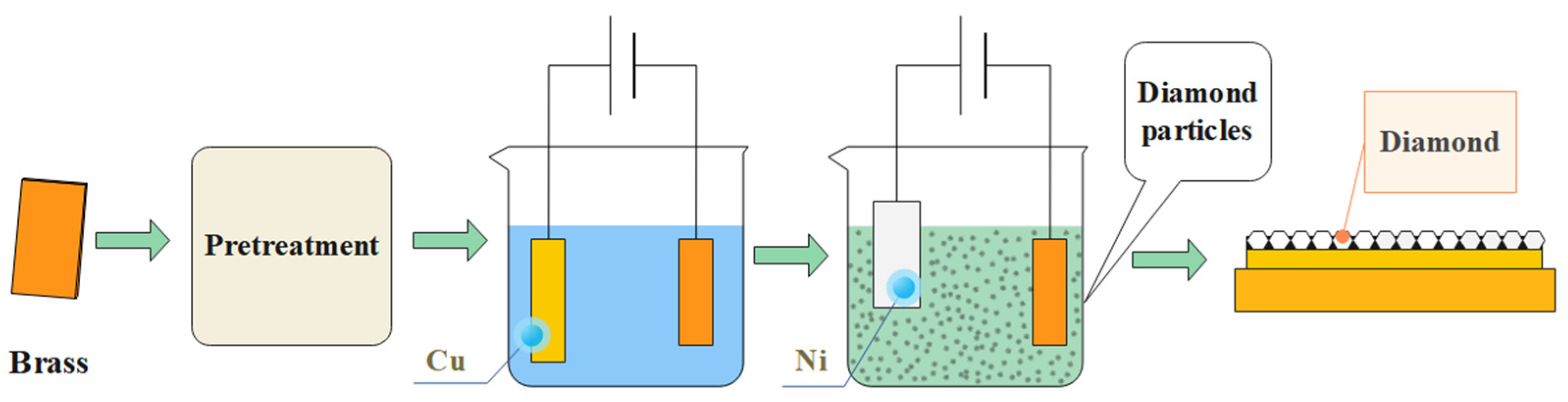
2. Experiment
3. Results and Discussion
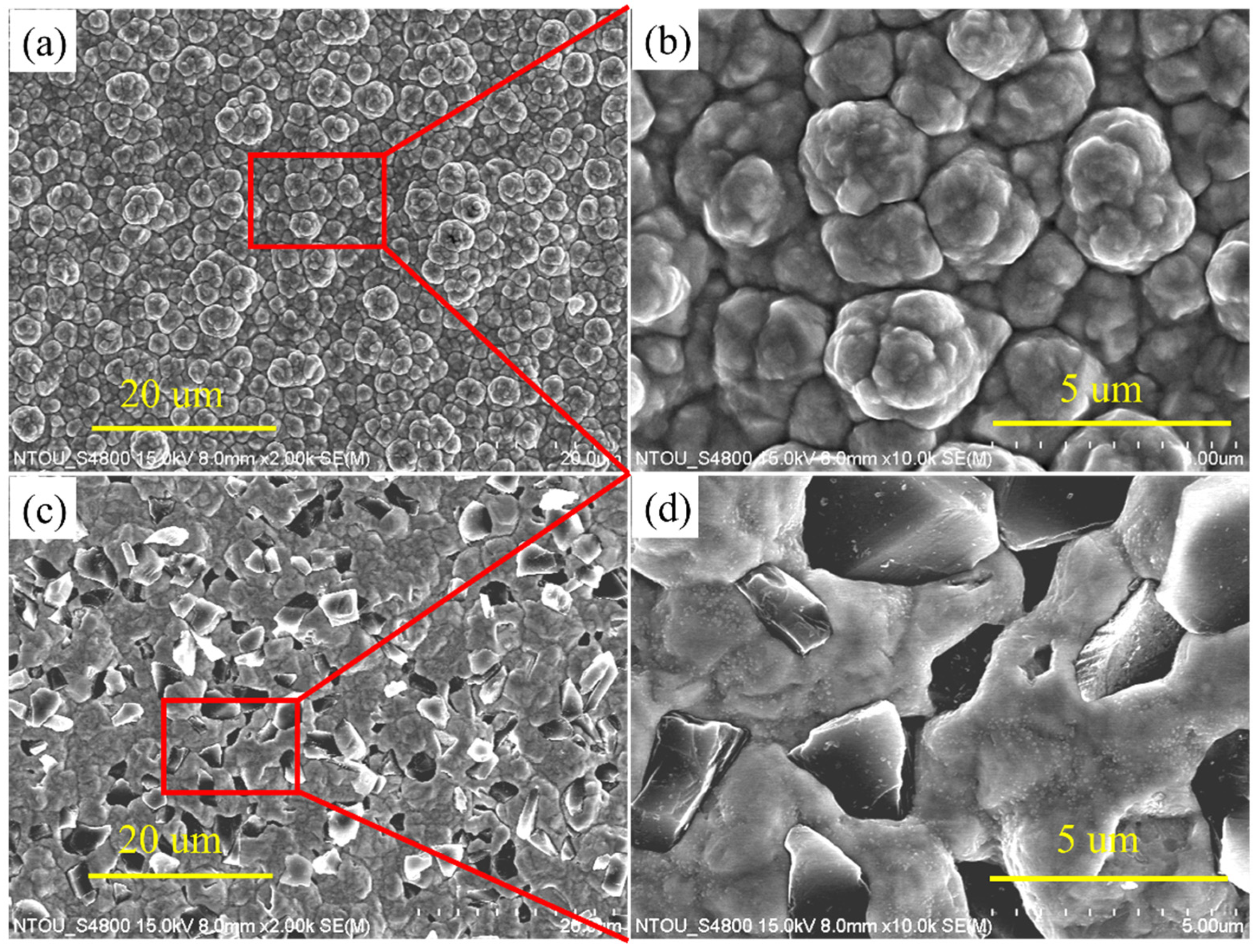
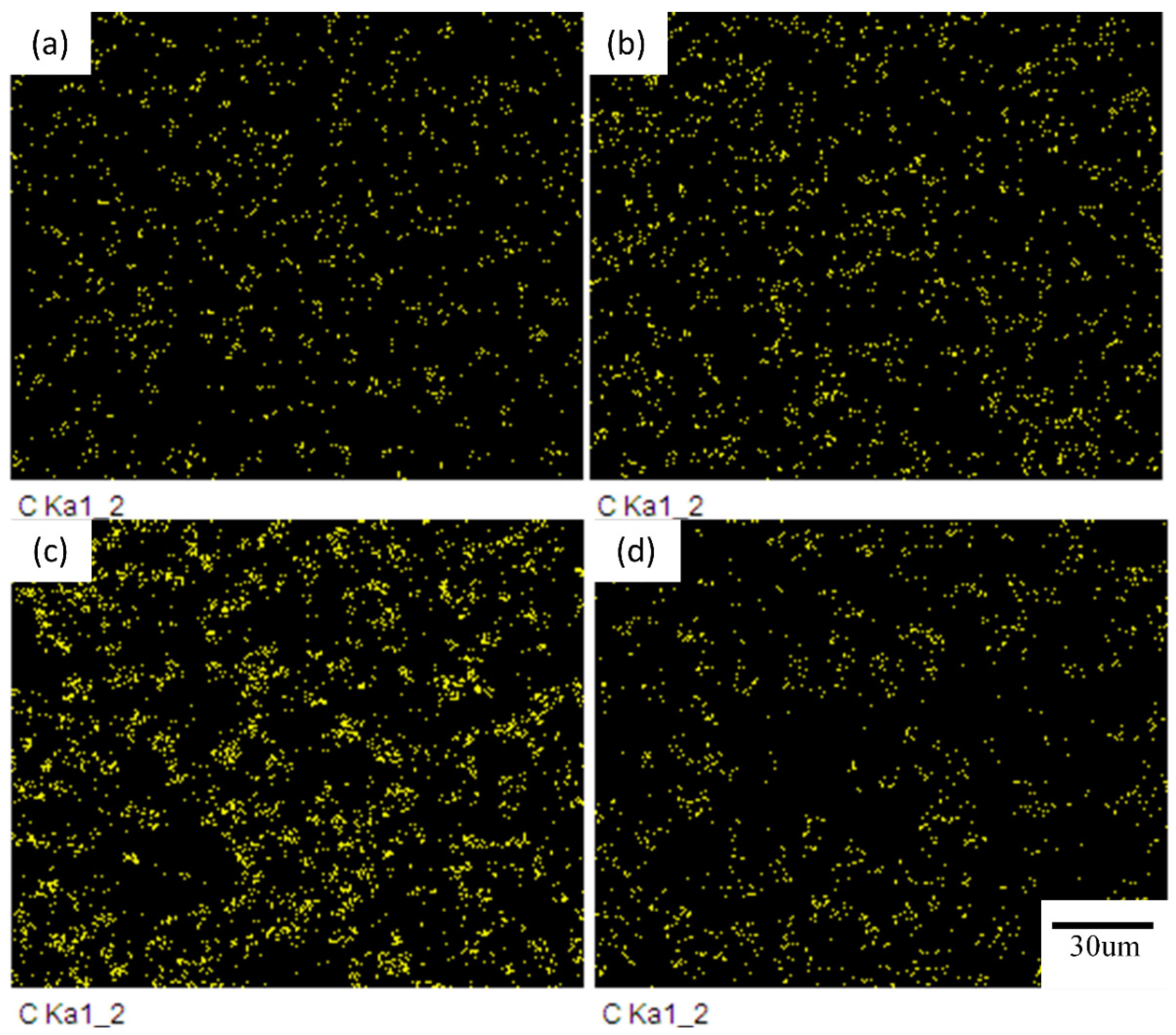
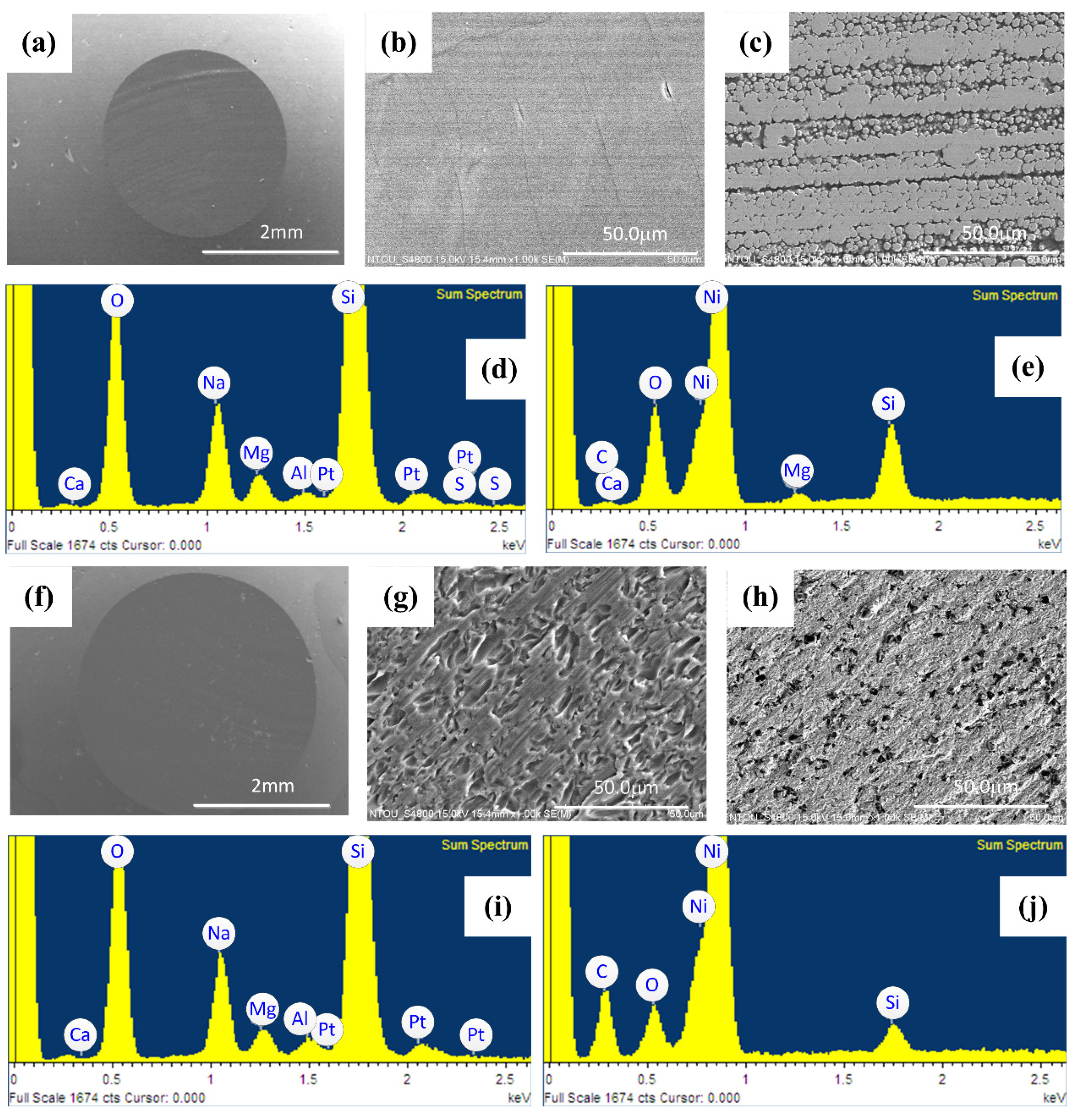
3.1. The Comparison of Surface Morphology
3.2. The Comparison of XRD Spectra
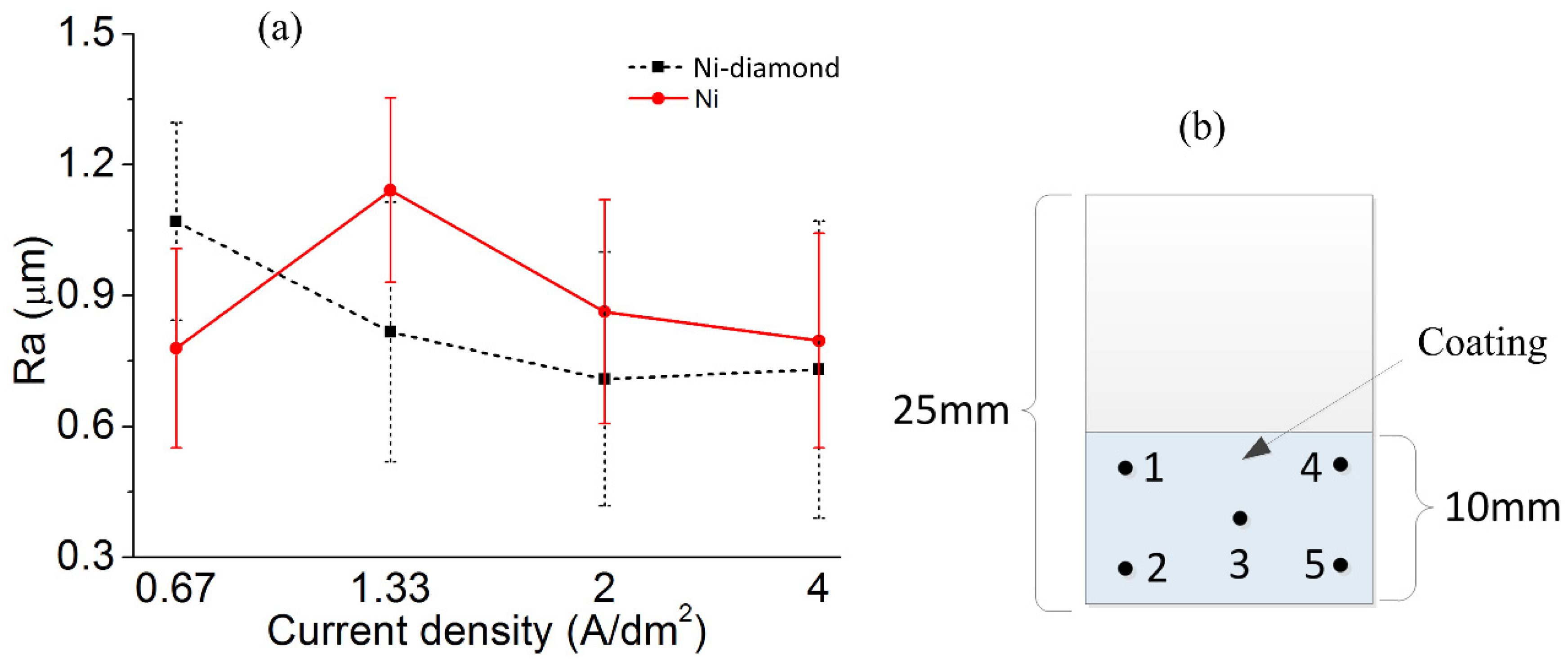
3.3. The Comparison of Surface Roughness
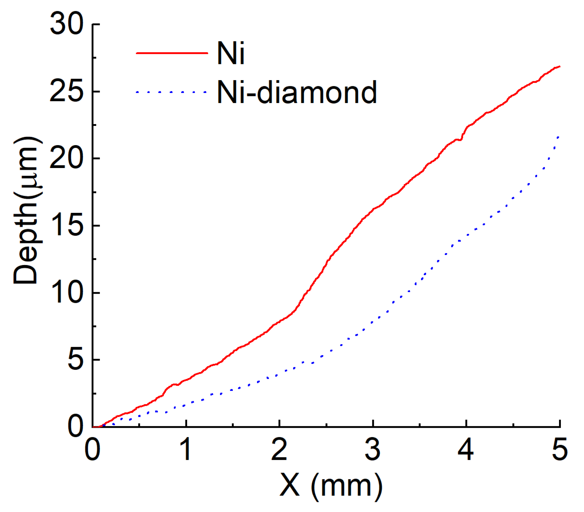
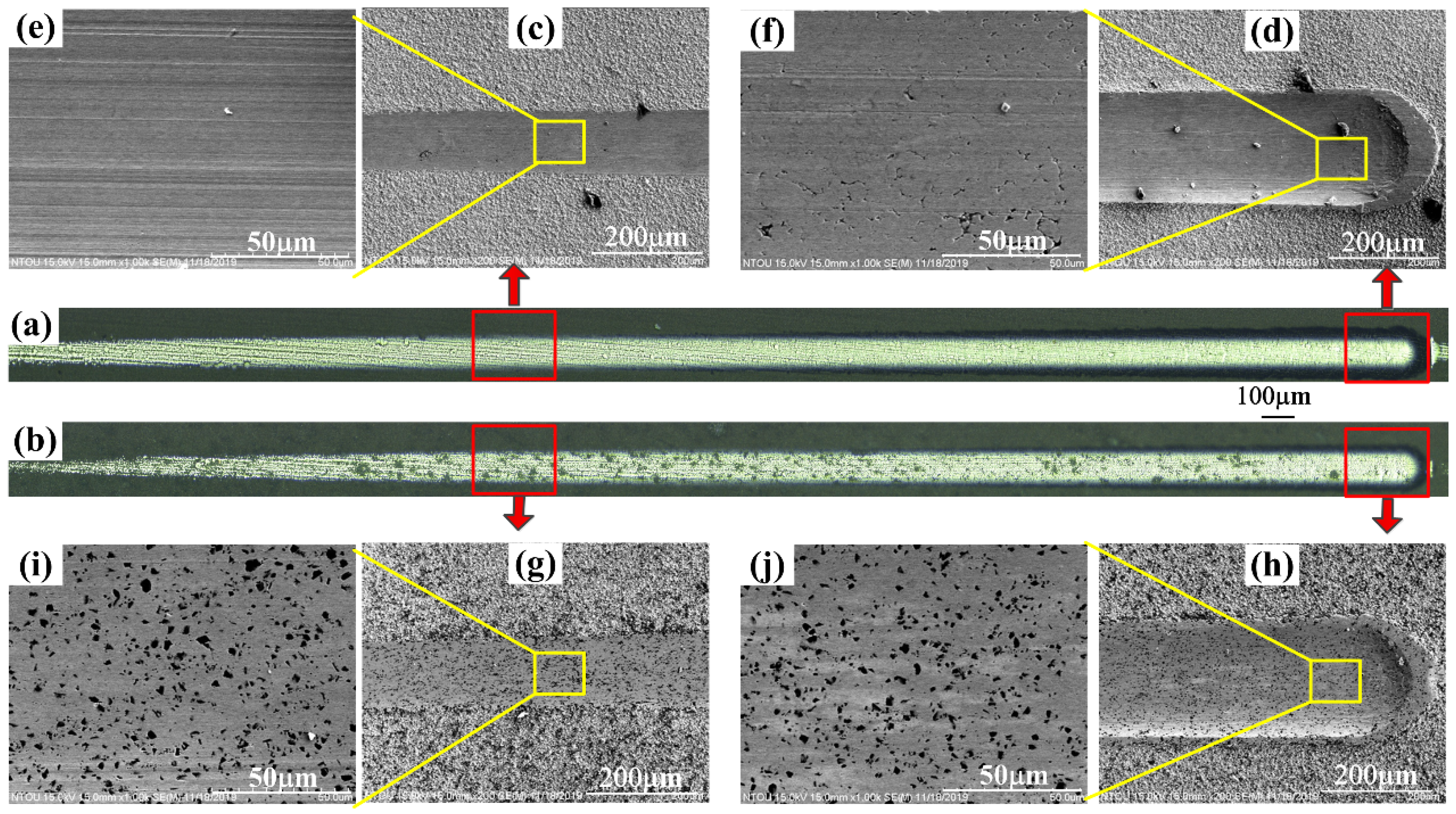
3.4. The Results of Scratch Tests
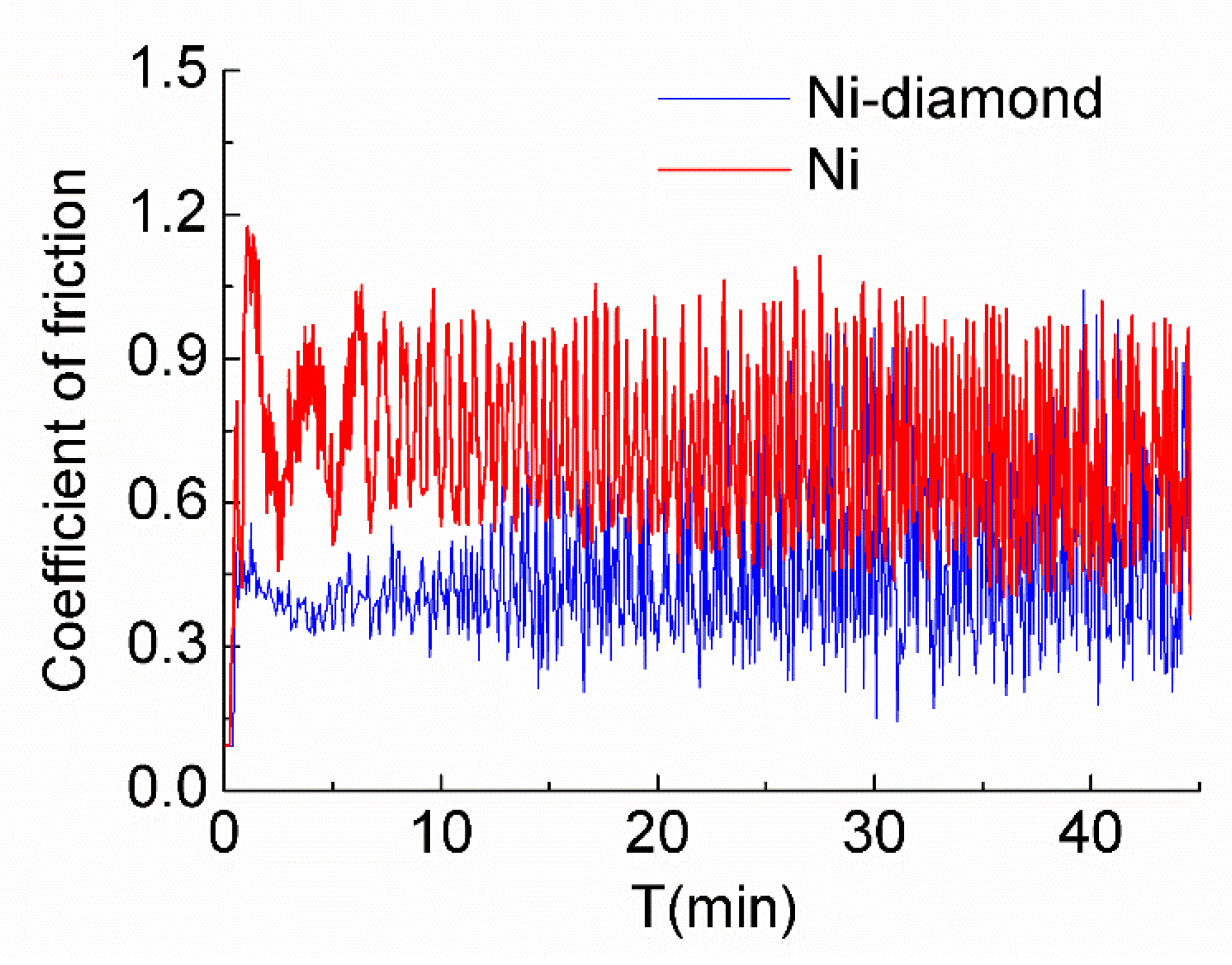
3.5. The Results of Wear Tests
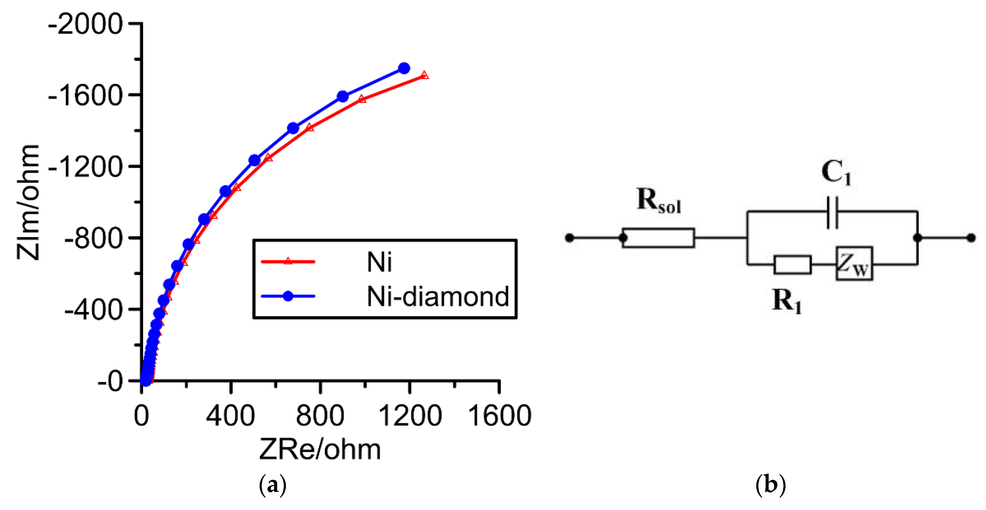
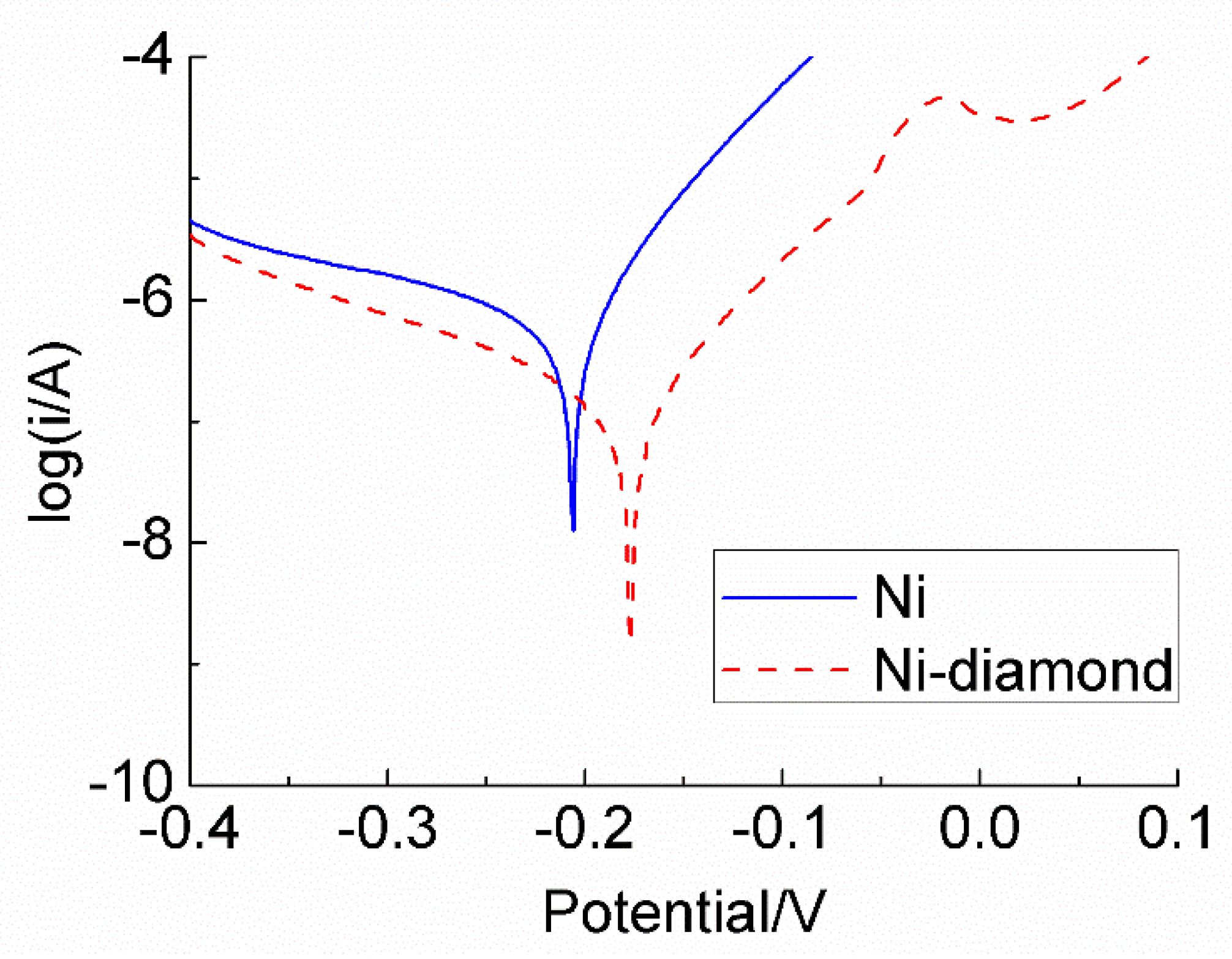
3.6. Results of Electrochemistry Test
4. Conclusions
- (1)
- With an increase in current density, the diamond particles and the distribution uniformity increased and then decreased. The angle offset of the crystallization direction of the Ni–diamond coating was minimal, indicating the low internal stress and the advantage of composite electrodeposition. In addition, the Ni–diamond coating had a tendency to be less rough than the Ni coating, which helped to improve surface evenness.
- (2)
- The results of the scratch test and the wear test showed that the Ni–diamond coating had a strong processing capacity and high surface-machining quality. The press-in mechanism of particles improved the wear resistance and helped to extend the service life of the tool.
- (3)
- The results of the EIS test and Tafel curve showed that the Ni–diamond coating had a lower corrosion current, which demonstrated that the corrosion resistance was enhanced.
Author Contributions
Funding
Institutional Review Board Statement
Informed Consent Statement
Data Availability Statement
Conflicts of Interest
References
- Luo, S.Y.; Tsai, Y.Y.; Chen, C.H. Studies on cut-off grinding of BK7 optical glass using thin diamond wheels. Mater. Process. Technol. 2006, 173, 321–329. [Google Scholar] [CrossRef]
- Pratap, A.; Patra, K.; Dyakonov, A.A. A comprehensive review of micro-grinding: Emphasis on toolings, performance analysis, modeling techniques, and future research directions. Int. J. Adv. Manuf. Technol. 2019, 104, 63–102. [Google Scholar] [CrossRef]
- Geng, R.; Yang, X.; Xie, Q.; Zhang, W.; Kang, J.; Liang, Y.; Li, R. Ultra-precision diamond turning of ZnSe ceramics: Surface integrity and ductile regime machining mechanism. Infrared. Phys. Technol. 2021, 115, 103706. [Google Scholar] [CrossRef]
- Das, M.K.; Li, R.; Qin, J.; Zhang, X.; Das, K.; Thueploy, A.; Limpanart, S.; Boonyongmaneerat, Y.; Ma, M.; Liu, R. Effect of electrodeposition conditions on structure and mechanical properties of Ni-W/diamond composite coatings. Surf. Coat. Technol. 2017, 309, 337–343. [Google Scholar] [CrossRef]
- Low, C.T.J.; Bello, J.O.; Wharton, J.A.; Wood, R.J.K.; Stokes, K.R.; Walsh, F.C. Electrodeposition and tribological characterisation of nickel nanocomposite coatings reinforced with nanotubular titanates. Surf. Coat. Technol. 2010, 205, 1856–1863. [Google Scholar] [CrossRef]
- Shen, X.; Wang, X.; Sun, F. Fabrication and evaluation of monolayer diamond grinding tools by hot filament chemical vapor deposition method. J. Mater. Process. Technol. 2019, 265, 1–11. [Google Scholar] [CrossRef]
- Warhanek, M.; Walter, C.; Hirschi, M.; Boos, J.; Bucourt, J.F.; Wegener, K. Comparative analysis of tangentially laser-processed fluted polycrystalline diamond drilling tools. J. Manuf. Process 2016, 23, 157–164. [Google Scholar] [CrossRef]
- Wang, Y.; Zhao, B.; Huang, S.; Qian, Z. Study on the subsurface damage depth of monocrystalline silicon in ultrasonic vibration assisted diamond wire sawing. Eng. Fract. Mech. 2021, 258, 108077. [Google Scholar] [CrossRef]
- Huang, J.; Lu, J.; Wang, Y.; Ma, Z. Fabrication of porous structure vitrified bond diamond grinding wheel via direct ink writing. Ceram. Int. 2021, 47, 34050–34058. [Google Scholar] [CrossRef]
- Zhao, Z.; Du, L.; Xu, Z.; Shao, L. Effects of ultrasonic agitation on adhesion strength of micro electroforming Ni layer on Cu substrate. Ultrason. Sonochem. 2016, 29, 1–10. [Google Scholar] [CrossRef]
- Hsue, A.W.J.; Chang, Y.F. Toward synchronous hybrid micro-EDM grinding of micro-holes using helical taper tools formed by Ni-Co/diamond Co-deposition. J. Mater. Process. Technol. 2016, 234, 368–382. [Google Scholar] [CrossRef]
- Zhou, H.; Du, N.; Zhu, L.; Shang, J.; Qian, Z.; Shen, X. Characteristics investigation of Ni-diamond composite electrodeposition. Electrochim. Acta 2015, 151, 157–167. [Google Scholar] [CrossRef]
- Chen, N.; Ju, F.; Zhou, F.; Chen, S.; Wei, K.; He, P. Growth and characterization of chemical vapor deposition diamond coating incorporated amorphous carbon with high Raman bands induced by CuO particles. Diam. Relat. Mater. 2021, 116, 108387. [Google Scholar] [CrossRef]
- Chou, C.C.; Lee, J.W.; Chen, Y.I. Tribological and mechanical properties of HFCVD diamond-coated WC-Co substrates with different Cr interlayers. Surf. Coat. Technol. 2008, 203, 704–708. [Google Scholar] [CrossRef]
- Deb, N.K.; Kalita, K.; Abhilash, S.R.; Giri, P.K.; Biswas, R.; Umapathy, G.R.; Kabiraj, D.; Chopra, S. Fabrication and characterization of thin targets of nickel (61,62Ni) isotopes by physical vapour deposition technique for nuclear reaction studies. Vacuum 2019, 163, 148–157. [Google Scholar] [CrossRef]
- Shi, X.; Wen, D.; Wang, S.; Wang, G.; Zhang, M.; Li, J.; Xue, C. Investigation on friction and wear performance of laser cladding Ni-based alloy coating on brake disc. Optik 2021, 242, 167227. [Google Scholar] [CrossRef]
- Hu, W.; Wan, L.; Liu, X.; Li, Q.; Wang, Z. Effect of TiO2/Al2O3 film coated diamond abrasive particles by sol–gel technique. Appl. Surf. Sci. 2011, 257, 5777–5783. [Google Scholar] [CrossRef]
- Huang, W.; Zhao, Y.; Wang, X. Preparing a high-particle-content Ni/diamond composite coating with strong abrasive ability. Surf. Coat. Technol. 2013, 235, 489–494. [Google Scholar] [CrossRef]
- Bao, H.; Li, Q.; Jia, H.; Yang, G. Mechanical properties comparison of Ni-diamond composite coatings fabricated by different methods. Mater. Res. Express 2019, 6, 106425. [Google Scholar] [CrossRef]
- Wang, J.; Zhang, F.L.; Zhang, T.; Liu, W.G.; Li, W.X.; Zhou, Y.M. Preparation of Ni-P-diamond coatings with dry friction characteristics and abrasive wear resistance. Int. J. Refract. Met. Hard Mater. 2018, 70, 32–38. [Google Scholar] [CrossRef]
- Zhang, Y.; Feng, L.; Qiu, W. Enhancement of the wear resistance of Ni-diamond composite coatings via glycine modification. Diam. Relat. Mater. 2020, 109, 108086. [Google Scholar] [CrossRef]
- Zhang, W.; Mei, T.; Li, B.; Yang, L.; Du, S.; Miao, Y.; Chu, H. Effect of current density and agitation modes on the structural and corrosion behavior of Ni/diamond composite coatings. J. Mater. Res. Technol. 2021, 12, 1473–1485. [Google Scholar] [CrossRef]
- Li, B.; Mei, T.; Chu, H.; Wang, J.; Du, S.; Miao, Y.; Zhang, W. Ultrasonic-assisted electrodeposition of Ni/diamond composite coatings and its structure and electrochemical properties. Ultrason. Sonochem. 2021, 73, 105475. [Google Scholar] [CrossRef]
- Sajjadnejad, M.; Omidvar, H.; Javanbakht, M.; Mozafari, A. Textural and structural evolution of pulse electrodeposited Ni/diamond nanocomposite coatings. J. Alloys Compd. 2017, 704, 809–817. [Google Scholar] [CrossRef]
- Wang, X.; Chou, C.C.; Yang, Y.C.; Wu, R.; Lee, J.W.; Chang, H.Y. Tribological and mechanical properties of Cu/Ni-microdiamond bilayers on brass substrates coated by composite electrodeposition technology. Surf. Topogr.-Metrol. 2020, 8, 024005. [Google Scholar] [CrossRef]
- Wang, X.; Chou, C.C.; Wu, L.T.; Wu, R.; Lee, J.W.; Chang, H.Y. Improvement of the Adhesion and Diamond Content of Electrodeposited Cu/Microdiamond Composite Coatings by a Plated Cu Interlayer. Materials 2021, 14, 2571. [Google Scholar] [CrossRef]
- Wang, X.; Chou, C.C.; Lee, J.W.; Wu, R.; Chang, H.Y.; Ding, Y. Preparation and investigation of diamond-incorporated copper coatings on a brass substrate by composite electrodeposition. Surf. Coat. Technol. 2020, 386, 125508. [Google Scholar] [CrossRef]
- Wang, Z.; Shen, L.; Jiang, W.; Fan, M.; Liu, D.; Zhao, J. Superhydrophobic nickel coatings fabricated by scanning electrodeposition on stainless steel formed by selective laser melting. Surf. Coat. Technol. 2019, 377, 124886. [Google Scholar] [CrossRef]
- Shen, L.; Xu, M.; Jiang, W.; Qiu, M.; Fan, M.; Ji, G.; Tian, Z. A novel superhydrophobic Ni/Nip coating fabricated by magnetic field induced selective scanning electrodeposition. Appl. Surf. Sci. 2019, 489, 25–33. [Google Scholar] [CrossRef]
- Jiang, W.; Shen, L.; Xu, M.; Wang, Z.; Tian, Z. Mechanical properties and corrosion resistance of Ni-Co-SiC composite coatings by magnetic field-induced jet electrodeposition. J. Alloys Compd. 2019, 791, 847–855. [Google Scholar] [CrossRef]
- Zhuo, W.; Shen, L.; Qiu, M.; Tian, Z.; Jiang, W. Effects of flexible friction on the properties of nanocrystalline nickel prepared by jet electrodeposition. Surf. Coat. Technol. 2018, 333, 87–95. [Google Scholar] [CrossRef]
- Mishra, R.; Balasubramaniam, R. Effect of nanocrystalline grain size on the electrochemical and corrosion behavior of nickel. Corros. Sci. 2004, 46, 3019–3029. [Google Scholar] [CrossRef]
- Awasthi, S.; Goel, S.; Pandey, P.C.; Balani, K. Multi-Length Scale Tribology of Electrophoretically Deposited Nickel-Diamond Coatings. JOM 2016, 2, 227–235. [Google Scholar] [CrossRef]
- Houa, K.; Wang, H.; Sheuc, H.; Ger, M. Preparation and wear resistance of electrodeposited Ni–W/diamond composite coatings. Appl. Surf. Sci. 2014, 30, 372–379. [Google Scholar] [CrossRef]
- Makarova, I.; Dobryden, I.; Kharitonov, D.; Kasach, A.; Ryl, J.; Repo, E. Vuorinen, Nickel-nanodiamond coatings electrodeposited from tartrate electrolyte at ambient temperature. Surf. Coat. Technol. 2019, 380, 125063. [Google Scholar] [CrossRef]
- Hefnawy, A.; Elkhoshkhany, N.; Essam, A. Ni–TiN and Ni-Co-TiN composite coatings for corrosion protection: Fabrication and electrochemical characterization. J. Alloys Compd. 2018, 735, 600–606. [Google Scholar] [CrossRef]


| (<111>) | β (Radian) | 2θ (°) | Crystallite Size D (nm) |
|---|---|---|---|
| Ni | 0.3634 | 44.47 | 23.64 |
| Ni-0.67 | 0.4705 | 44.53 | 18.26 |
| Ni-1.33 | 0.4682 | 44.53 | 18.35 |
| Ni-2 | 0.4988 | 44.53 | 17.22 |
| Ni-4 | 0.5258 | 44.53 | 16.34 |
| Ni–diamond-0.67 | 0.4638 | 44.51 | 18.52 |
| Ni–diamond-1.33 | 0.4458 | 44.51 | 19.27 |
| Ni–diamond-2 | 0.4539 | 44.57 | 18.93 |
| Ni–diamond-4 | 0.5443 | 44.55 | 15.78 |
| Coating Layers | Rsol (ohm) | R1 (ohm) | C1 (F) | ZW (ohm) |
|---|---|---|---|---|
| Cu_Ni | 27.78 | 3728 | 0.6293 × 10⁻³ | 0.01262 |
| Cu_Ni–diamond | 18.44 | 3960 | 0.6510 × 10⁻³ | 0.01357 |
Publisher’s Note: MDPI stays neutral with regard to jurisdictional claims in published maps and institutional affiliations. |
© 2022 by the authors. Licensee MDPI, Basel, Switzerland. This article is an open access article distributed under the terms and conditions of the Creative Commons Attribution (CC BY) license (https://creativecommons.org/licenses/by/4.0/).
Share and Cite
Wang, X.; Zhao, Z.; Chen, J.; Zhou, X.; Zong, Y. Microstructure, Wear and Corrosion Behaviors of Electrodeposited Ni-Diamond Micro-Composite Coatings. Coatings 2022, 12, 1391. https://doi.org/10.3390/coatings12101391
Wang X, Zhao Z, Chen J, Zhou X, Zong Y. Microstructure, Wear and Corrosion Behaviors of Electrodeposited Ni-Diamond Micro-Composite Coatings. Coatings. 2022; 12(10):1391. https://doi.org/10.3390/coatings12101391
Chicago/Turabian StyleWang, Xiaoli, Ziyi Zhao, Jinsong Chen, Xin Zhou, and Yinjie Zong. 2022. "Microstructure, Wear and Corrosion Behaviors of Electrodeposited Ni-Diamond Micro-Composite Coatings" Coatings 12, no. 10: 1391. https://doi.org/10.3390/coatings12101391
APA StyleWang, X., Zhao, Z., Chen, J., Zhou, X., & Zong, Y. (2022). Microstructure, Wear and Corrosion Behaviors of Electrodeposited Ni-Diamond Micro-Composite Coatings. Coatings, 12(10), 1391. https://doi.org/10.3390/coatings12101391