Article

Three-Dimensional Carbon-Coated LiFePO4 Cathode with Improved Li-Ion Battery Performance

1
Wuhan Institute of Marine Electric Propulsion, China Shipbuilding Industry Corporation, Wuhan 430074, China
2
Engineering Research Center of Nano-Geomaterials of Ministry of Education, Faculty of Material Science and Chemistry, China University of Geosciences, Wuhan 430074, China
3
State Key Laboratory of Advanced Technology for Materials Synthesis and Processing, Wuhan University of Technology, Wuhan 430070, China
*
Authors to whom correspondence should be addressed.
These authors contributed equally to this work.
Coatings 2021, 11(9), 1137; https://doi.org/10.3390/coatings11091137
Submission received: 18 August 2021 / Revised: 5 September 2021 / Accepted: 13 September 2021 / Published: 18 September 2021
(This article belongs to the Special Issue Surface Coating in Advanced Energy Storage Devices)

Abstract

:
LiFePO4 (LFPO)has great potential as the cathode material for lithium-ion batteries; it has a high theoretical capacity (170 m·A·h·g−1), high safety, low toxicity and good economic benefits. However, low conductivity and a low diffusion rate inhibit its future development. To overcome these weaknesses, three-dimensional carbon-coated LiFePO4 that incorporates a high capacity, superior conductivity and low volume expansion enables faster electron transport channels. The use of Cetyltrimethyl Ammonium Bromid (CTAB) modification only requires a simple water bath and sintering, without the need to add a carbon source in the LFPO synthesis process. In this way, the electrode shows excellent reversible capacity, as high as 159.8 m·A·h·g−1 at 2 C, superior rate capability with 97.3 m·A·h·g−1 at 5 C and good cycling ability, preserving ~84.2% capacity after 500 cycles. By increasing the ion transport rate and enhancing the structural stability of LFPO nanoparticles, the LFPO-positive electrode achieves excellent initial capacity and cycle life through cost-effective and easy-to-implement carbon coating. This simple three-dimensional carbon-coated LiFePO4 provides a new and simple idea for obtaining comprehensive and high-performance electrode materials in the field of lithium cathode materials.

1. Introduction

Nowadays, with the rapid and sustainable development of energy, people have gradually shifted their attention from traditional fossil energy to new clean energy, and lithium-ion batteries (LIB) being a form of this [1,2,3,4,5,6,7]. Over the past few decades, LIBs have dominated the portable electronics market due to their much higher energy density compared with other energy storage systems. They have been widely used in traffic applications in hybrid electric vehicles (HEV), plug-in hybrid electric vehicles (PHEV) and electric vehicles (EV) to reduce environmental pollution, and further consideration is being given to store and utilize intermittent renewable energy such as solar and wind energy [8,9,10,11]. Since Padhi et al.’s groundbreaking report in 1997, LiFePO4 has attracted significant attention and has been widely used as a LIB cathode material because of its high theoretical capacity (170 m·A·h·g−1), high safety, low toxicity and the possibility of good economic benefits [12,13,14,15]. However, further development has been limited due to its low conductivity and slow lithium ion diffusion rate [16,17]. Researchers have made substantial efforts to address this issue, such as cation doping [18], surface coating [19,20,21,22,23,24], morphological control [25] and electrolyte modification [26].
Recently, with the deepening of the understanding of electrode materials, it has been found that the surface structure of electrode materials has an important effect on the electrochemical performance of Li-ion batteries. Carbon coating can efficiently enhance the conductivity of the electrode, improve the surface chemistry of the active substance and protect the electrode from direct contact with the electrolyte, thus increasing the cycle life of the battery. Carbon coating, together with nanotechnology, offers good electrical conductivity and rapid diffusion of lithium ions, which also results in good rate capability. Therefore, carbon coating is an efficient approach to promote the performance of electrode materials for lithium-ion batteries. As a cathode material for lithium-ion batteries, LFPO has a 500-billion market capacity, the third largest market capacity, but it has the key problem of poor electrical conductivity. The addition of a conductive carbon layer can significantly solve this problem; as previously reported [27,28,29,30], more graphene oxide can be added as a conductive carbon layer. For example, Li [31] et al. used graphene-modified LFPO to achieve a capacity of 208 m·A·h·g−1 beyond the theoretical capacity at 0.1 C, and Park [32] et al. used graphene-modified LFPO to achieve a capacity of 171.9 m·A·h·g−1 above theoretical capacity at 0.1 C. However, the production of GO is complex and dangerous, so it is imperative to find a method for the synthesis of conductive carbon layers with good safety that is simple and allows for mass production. Therefore, some researchers have begun exploring direct carbon coating. For example, Cui et al. [33] use CTAB to achieve carbon coating of porous silicon micron-sized particles for lithium battery anodes, Cheng et al. [34] use Bis-GMA to achieve carbon-coated NbO2 for lithium battery anodes and Guo et al. [35] use PAN to achieve carbon-coated SnO2 for lithium battery anodes.
Herein, we demonstrate that by using CTAB to obtain three-dimensional carbon-coated LiFePO4, the performance of the electrode materials can be significantly enhanced. The carbon layer at the surface of LiFePO4 nanoparticles was obtained from a simple water bath and sintering. When used as the electrode material of LIBs, during the charge/discharge process, the carbon layer can effectively inhibit the volume expansion of LiFePO4 nanoparticles in the process of insertion/de-insertion [36]. A thin layer of carbon covering the surface of LiFePO4 can remarkably improve the conductivity of the electrode and speed up ion and electron transfer rates. In the meantime, the surface active sites of LiFePO4 nanoparticles were increased by the covering of the carbon layer, thus increasing the capacity even closer to 170 m·A·h·g−1. The electrode shows excellent reversible capacity as high as 159.8 m A h g−1 at 2 C, good rate capability with 97.3 m·A·h·g−1 at 5 C and prominent cycle ability, preserving ~ 84.2% capacity after 500 cycles. As shown in Table S1 [27,30,37,38,39,40,41], we compared the capacity of our 3D carbon-modified LFPO with that of other published materials, and it is clear that our material performs an excellent capacity at a relatively high current density, while the synthesis method is relatively simple. The three-dimensional carbon-coated LiFePO4 is regarded as a promising electrode material for LIBs.

2. Materials and Methods

2.1. Materials Synthesis

LiFePO4 and CTAB were purchased from Sinopharm Chemical Reagent Co. Ltd., (Shanghai, China) at analytical grade. All chemicals were used as received without further treatment. For a representative synthesis, 5 g LiFePO4 and 0.75 g CTAB were added into 100 mL of H2O at 80 °C under vigorous stirring for 8 h. After reaction, the precipitates were collected and cleaned thoroughly, followed by drying in a ventilated drying oven at 80 °C for 24 h. Finally, the obtained product was further annealed at 500 or 800 °C for 3 h in N2 with a ramping rate of 2 °C·min−1 and furnace-cooled to room temperature to obtain the target samples. We defined LiFePO4 without CTAB as LFPO, added 0.75 g (mass fraction 15%) of CTAB at sintering temperature of 500 °C as LFPO_15%_500 °C and added 0.75g (mass fraction 15%) of CTAB at sintering temperature of 800 °C, defined as LFPO_15%_800 °C. We also prepared LFPO_5%_500 °C and LFPO_5%_800 °C, LFPO_10%_500 °C and LFPO_10%_800 °C and LFPO_20%_500 °C and LFPO_20%_800 °C in the same way. (In order to avoid ambiguity, we have explained the definitions of various abbreviations in Tables S3 and S4.)

2.2. Characterization

X-ray diffraction (XRD) data were collected using Cu Kα radiation (λ = 1.5418 Å) in the 2θ (5°–90°) at room temperature by a Bruker D8 Discover X-ray diffractometer (Bruker, Karlsruhe, Germany). Field-emission scanning electron microscopy (FESEM) and energy dispersive X-ray spectra (EDS) were recorded by JEOL-7100F (JEOL, Tokyo, Japan). Brurauer–Emmerr–Teller (BET) surface areas were tested with a micromeritics TriStar II Surface Area (Micromeritics, Norcross, GA, USA) and Porosity by adsorption of nitrogen at 80 °C. Transmission electron microscopy (TEM) and high-resolution transmission electron microscopy (HRTEM) images associated with selected area electron diffraction (SAED) were collected by a JEM-2100F microscope (JEM, Tokyo, Japan).

2.3. Electrochemical Measurements

The 2016 coin batteries were assembled in a glove box filled with argon. In lithium half batteries, lithium metal was used as the anode, 1 M solution of LiPF6 in ethylene carbonate (EC)/dimethyl carbonate (DMC) (EC:DMC = 1:1, w%) was used as the electrolyte and glass fiber (GF/A) from Whatman was used as the separator. The working electrode was prepared by mixing the as-synthesized samples with carbon black and polyvinylidene fluoride (PVDF) in a weight ratio of 70:20:10. After coating it with aluminum foil, the electrode film was uniformly cut into circular slices over an area of ~0.4 cm2 and a mass loading of 1.0–2.5 mg·cm−2. Galvanostatic charge/discharge measurements were performed at a potential window ranging from 2.5–4.2 V (vs. Li+/Li) using a multi-channel battery testing system by LAND CT3001A (LAND, Wuhan, China). The test current is represented by C, 1 C = 170 mA·g−1. Cycle voltammetry (CV) and Electrochemical Impedance Spectra (EIS) were performed using an electrochemical workstation by CHI 760E (CHI, Shanghai, China). The EIS test frequency range was 0.01–100 kHZ, amplitude was 5 mV and the initial voltage was the open-circuit voltage of the battery. All tests were performed at room temperature. We show more detailed test standard parameters in Table S5 and in order to demonstrate the electrochemical measurements more clearly, we show the physical picture of the test in Figure S10.

3. Results and Discussion

Figure 1a depicts the X-ray diffraction patterns (XRD) of LFPO, LFPO_15%_500 °C and LFPO_15%_800 °C. Sharp diffraction peaks could be consistent in patterns corresponding to highly crystalline structures. All the main peaks could be well-matched to the monoclinic layered structure LiFePO4 (JCPDS No. 01-081-1173); the lattice parameters are refined to be a = 10.3320 Å, b = 6.0100 Å and c = 4.6920 Å with α = β = γ = 90°, corresponding with a space group of P62. When the pure-LFPO nanoparticles were coated with carbon which was sintered by CTAB, the structure of the nanoparticles was preserved with a peak belonging to LFPO. These results demonstrate that carbon sintered by CTAB not only does not change the crystalline phase of LFPO, but also provides a protective layer for LFPO nanoparticles to inhibit volume expansion and improve electrical conductivity.
The LFPO crystal has a layered structure consisting of FeO6 octahedra and PO4 tetrahedra and an oxygen atom point-shared with neighboring PO4 tetrahedra and FeO6 octahedral, as shown in Figure 1b. The lithium atoms are sandwiched between these FeO6 octahedra and PO4 tetrahedra. The O atoms in LFPO are in a single configuration which is surrounded by 1 Fe and 1 P. In some lithium-based oxide cathode materials, one of the reasons for structural degradation is the movement of metal ions from the octahedral to a tetrahedral site. Since the thin carbon layer can protect the LFPO, the volume of carbon-coated LFPO is probably free from the migration of the Li ion.
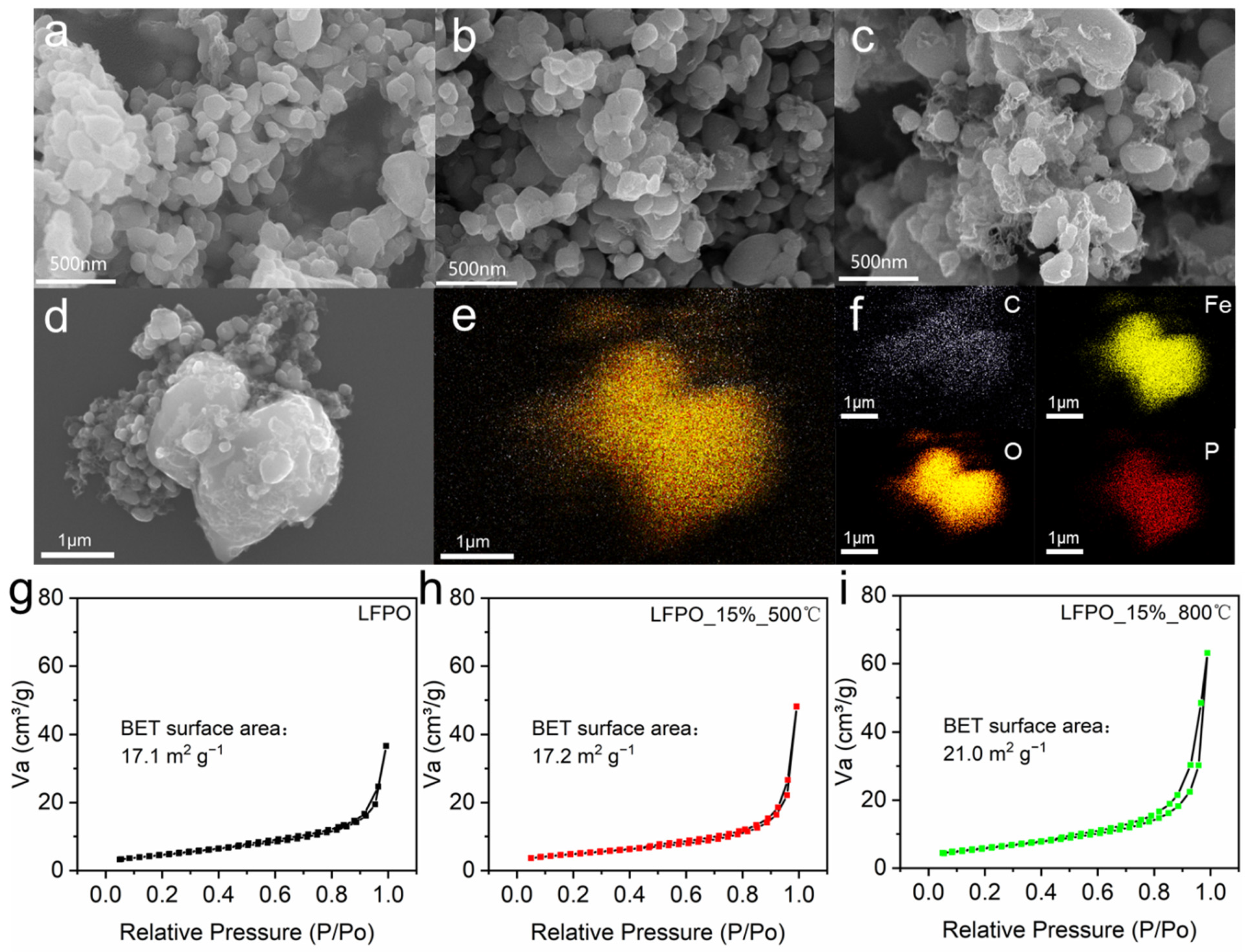
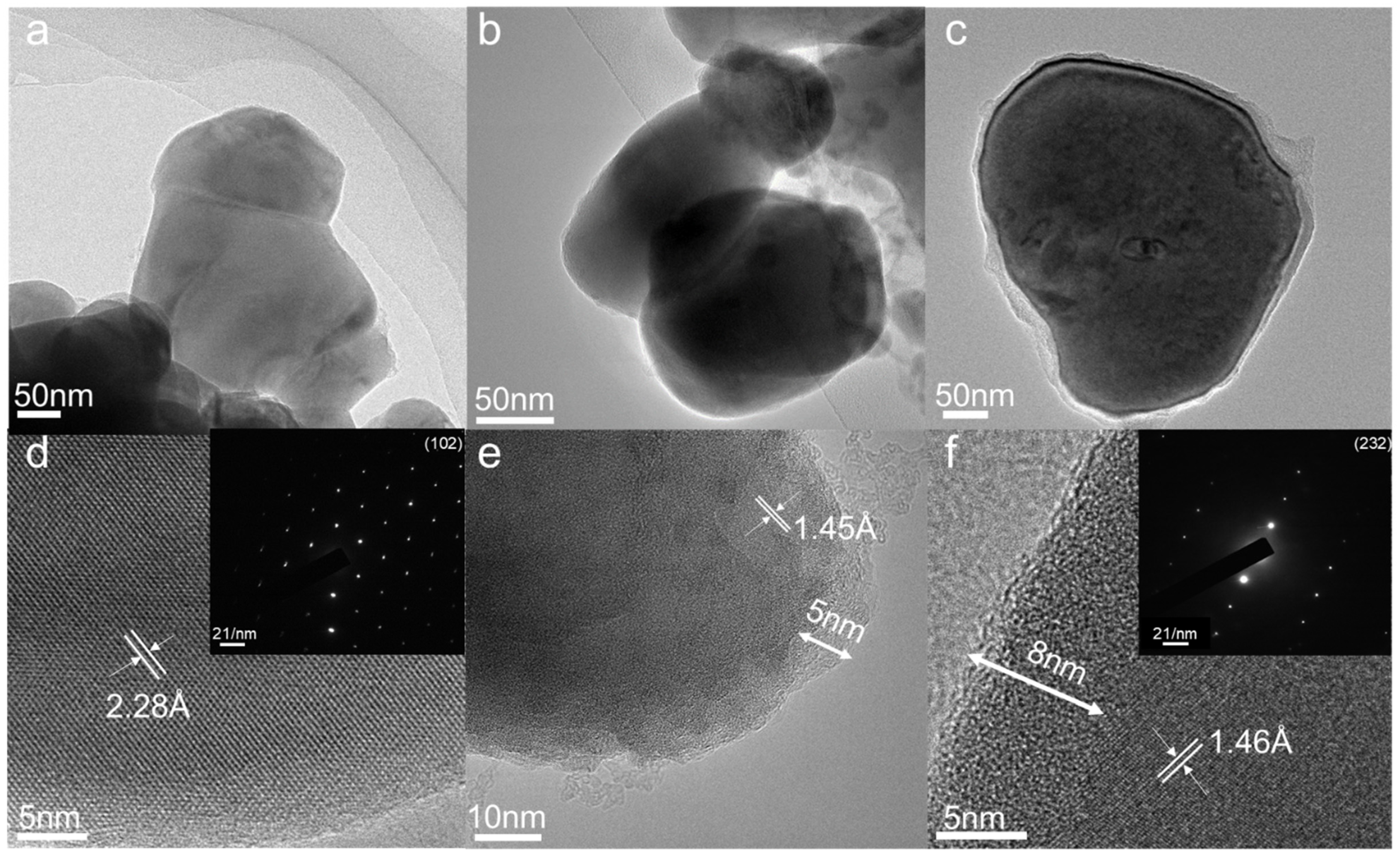
We characterized the individual SEM images of the pure LFPO, LFPO_15%_500 °C and LFPO_15%_800 °C (Figure 2a–c). For the pure LFPO, the morphology is of regular shape with a particle size of 100–300 nm (Figure 2a), and LFPO nanoparticles have a fairly smooth surface. As depicted in Figure 2b,c, when the annealing temperature is 500 °C, the surface of particles began to become rough and was covered with a small amount of floccule (Figure 2b). When increasing the annealing temperature to 800 °C, it is clear that the surface of particles became rougher and was covered in a great deal of flocculent substance (Figure 2c). It can be seen that when the CTAB doping amount is 15%, the floccule on the surface of LFPO nanoparticles increases with the increase of the sintering temperature. In order to verify whether the flocculent substance is carbon, the EDS test was performed on LFPO_15%_800 °C, as shown in Figure 2d–f. Observation from the EDS image shows that the surface of LFPO nanoparticles is covered with a layer of carbon, which can be seen from the brightness of EDS as a carbon layer and their even distribution on the surface of the LFPO. At the same time, EDS also shows the uniform distribution of P, O and Fe (Li cannot be detected due to its relatively small molecular mass), indicating that the addition of a carbon layer does not impact the structure of LFPO nanoparticles. As can be seen from Figure 2g–i, N2 adsorption–desorption measurements indicated that LFPO_15%_800 °C has a BET surface area of ∼21.0 m2·g−1 (Figure 2i) bigger than that of LFPO (~16.0 m2·g−1, Figure 2g) and LFPO_15%_500 °C (~17.2 m2·g−1, Figure 2h). BET surface area increases with the rise of temperature. The test results of BET correspond well with SEM and EDS. With the increase of the carbon layer, the BET surface area does increase, indicating that the carbon layer coating the LFPO has a significant effect. As shown in Figure S1 from the BET surface areas of LFPO_5%_500 °C (~16.0 m2·g−1, Figure S1a) and LFPO_5%_800 °C (~15.2 m2·g−1, Figure S1d), LFPO_10%_500 °C (~16.4 m2·g−1, Figure S1b) and LFPO_10%_800 °C (~16.1 m2·g−1, Figure S1e), LFPO_20%_500 °C (~15.4 m2·g−1, Figure S1c) and LFPO_20%_800 °C (~18.8 m2·g−1, Figure S1f), it is not hard to see that the doped CTAB and the sintering temperature must be suitable to increase the BET surface area and thus the capacity. At the same time, TEM, HRTEM and corresponding SAED tests were also performed to further observe the carbon layer on the surface of LFPO nanoparticles. As shown in Figure 3a–c and Figure S2a, the surface of LFPO nanoparticles is surrounded by a thin layer of carbon flocculation, and the thickness gradually increases with the increase of temperature. Through HRTEM of LFPO, LFPO_15%_500 °C and LFPO_15%_800 °C in Figure 3d–f and Figure S2b, it can be further observed that through three-dimensional carbon coating, the carbon layer on the surface of LFPO nanoparticles increases from 0 to 5 nm and then to 8 nm, indicating that the carbon layer covering is indeed realized. The corresponding selected area electron diffraction (SAED) patterns in the illustrations in Figure 3d,f represent the single crystallinity of LFPO and that carbon coating does not change the lattice orientation of LFPO nanoparticles. As shown in Figure S3, it can be clearly seen that with the increase of temperature, the mass loss rate of LFPO increases, indicating that the amount of carbon on the surface of LFPO increases. According to previous reports, [42,43,44,45] at about 400 °C, LiFePO4 will be oxidized into Li3Fe2(PO4)3 and Fe2O3, resulting in a mass increase. Therefore, the TG curve will rise first and then decline, and the declining part represents the content of carbon. According to the results of TEM and TGA, we conclude that the thickness of the carbon layer increases with the increase of the sintering temperature. All these results show that CTAB-modified LFPO can indeed achieve three-dimensional carbon-coated LFPO and improve the BET surface area.
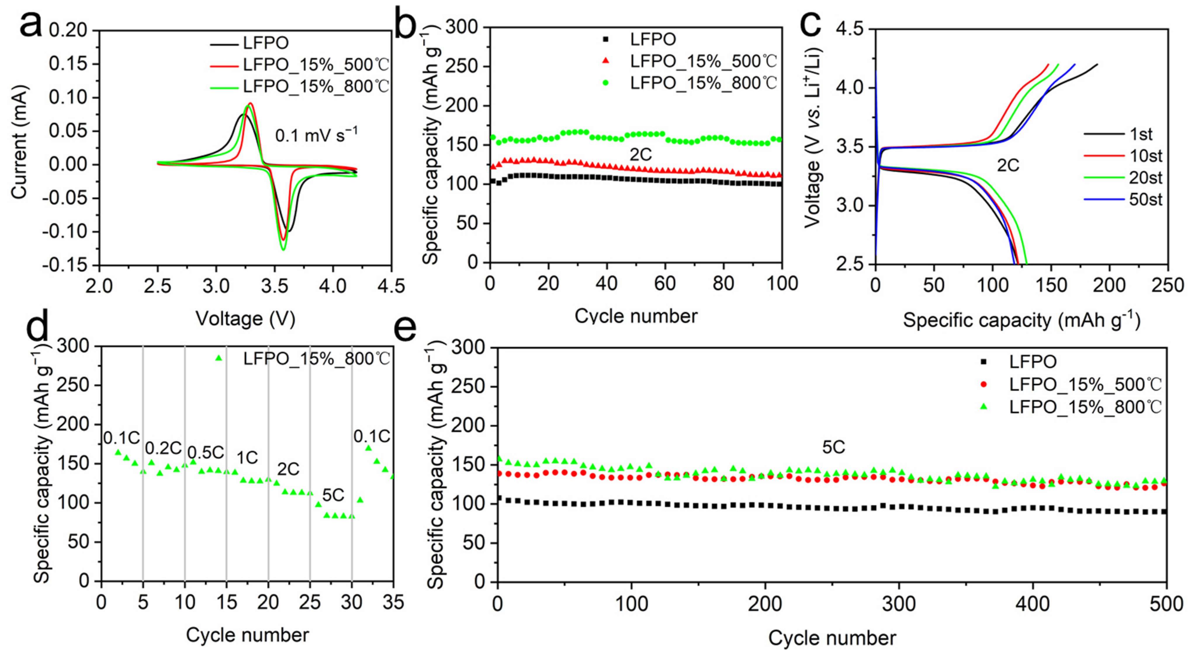
Coin-type cells are assembled to investigate the lithium storage performances. CV curves of LFPO, LFPO_15%_500 °C and LFPO_15%_800 °C are measured at a scan rate of 0.1 mV·s−1 from 2.5 to 4.2 V (vs. Li+/Li) at room temperature (Figure 4a). Generally speaking, three samples exhibit semblable CV curves, implying their identical electrochemical behaviors. The CV curves show that the reduction peaks appear at ~3.6 V, corresponding to the reduction of the formation of a solid electrolyte interphase (SEI) layer. One oxidation peak at ~3.3 V can be observed which may be imputed to the oxidation of Li to Li+. The areas of CV curves for LFPO_15%_800 °C are larger than LFPO and LFPO_15%_500 °C, indicating the higher capacity of LFPO_15%_800 °C. Figure S4 shows the typical CV curves of LFPO_15%_800 °C at various scan rates from 0.1 to 1.0 mV·s−1 in a voltage range of 2.5 to 4.2 V. The CV curves exhibit a similar shape, demonstrating that the lithiation/de-lithiation processes are highly reversible with few side reactions.
When the current density is 2 C, the first discharging capacity of LFPO_15%_800 °C is 159.8 m·A·h·g−1 with the initial coulombic efficiency of ~75%. Although the initial coulomb efficiency is only 75%, it increases with the charging and discharging process. As shown in Figure S5, good coulomb efficiency is achieved at different C rates. With the increase of the number of cycles, the capacity gradually stabilized and reached 156.9 m·A·h·g−1 after 100 cycles, showing a good cycling capacity (Figure 4b). However, the first discharging capacity of LFPO_15%_500 °C is 121.6 m·A·h·g−1 and reached 111.2 m·A·h·g−1 after 100 cycles; the first discharge capacity of LFPO is even lower, being only 103.9 m·A·h·g−1, and reached 100.0 m·A·h·g−1 after 100 cycles. The high electrode capacity of LFPO_15%_800 °C is probably because of (i) the carbon layer covering the surface of LFPO nanoparticles, which enhances the integral conductivity, and (ii) the carbon layer on the surface of LFPO nanoparticles inhibiting the volume expansion between Li insertion/de-insertion processes [21,27,28,43]. Therefore, the capacity is even closer to 170 m·A·h·g−1. It should be noted that LFPO_15%_500 °C exhibits capacity behavior and coulombic efficiency similar to LFPO_15%_800 °C. This result indicates that carbon coating can also be achieved at 500 °C, which improves the battery capacity and stability. It may be because the carbon layer is closely covered, so the BET area does not increase significantly. This is also confirmed by the charging-specific capacity at 5 C current density (Figure S6); LFPO_15%_500 °C and LFPO_15%_800 °C have a similar specific capacity and are both higher than LFPO. As shown in Figure S7, we also tested the cycling performance of LFPO_5%_500 °C and LFPO_5%_800 °C, LFPO_10%_500 °C and LFPO_10%_800 °C and LFPO_20%_500 °C and LFPO_20%_800 °C at 2 C current densities. Their capacity performance corresponds to the size of the BET surface area. Their capacity corresponds to the BET surface area. The larger the BET surface area, the higher the specific capacity. It can be seen that the BET surface area does not increase with the increase of sintering temperature [46,47], nor is a higher CTAB doping amount [48] better. LFPO_10%_500 °C and LFPO_20%_800 °C are higher than LFPO, LFPO_5%_500 °C and LFPO_10%_800 °C are close to LFPO and LFPO_5%_800 °C and LFPO_20%_500 °C are lower than LFPO. This also indicates that only can the sintering temperature and the CTAB doping amount’s effective collocation have a good and specific capacity gain effect. Figure 4c shows the charging and discharging voltage platform of LFPO_15%_800 °C, with the discharging platform at ~3.3 V and the charging platform at ~3.5 V. Moreover, each cycle platform is similar and each circulation platform corresponds well to the redox peak in Figure 4a, indicating its good cycling stability. The same is true for LFPO and LFPO_15%_800 °C in the case of 2 and 5 C (Figures S8 and S9).
The average charge capacities of 164, 150, 151, 138, 125 and 97 m·A·h·g−1 are obtained for LFPO_15%_800 °C at rates of 0.1, 0.2, 0.5, 1, 2 and 5 C, respectively (Figure 4d). Remarkably, when the current density returns to 0.1 C, it also indicates a capacity of up to 169 m·A·h·g−1. This performance demonstrates the excellent high-rate capability and outstanding cyclability of the LFPO_15%_800 °C. Besides superior specific capacity and good rate capability, LFPO_15%_800 °C and LFPO_15%_500 °C also show excellent cycling performance (Figure 4e). After 500 cycles, LFPO_15%_800 °C maintains a good capacity of 100.5 m·A·h·g−1 at a current density of 5 C and maintains ~84.2% of the first cycle discharge capacity, corresponding to a capacity decay of 0.0316% at each cycle. All these results show that LFPO nanoparticles can bind tightly to the carbon layer and greatly improve the overall cycling stability. This is because LFPO nanoparticles are uniformly fixed and firmly connected to the CTAB sintered nanofibers, resulting in a process of charge and discharge and an adaptive three-dimensional grid structure with strain relaxation ability formed to stabilize the charge and discharge cycles.
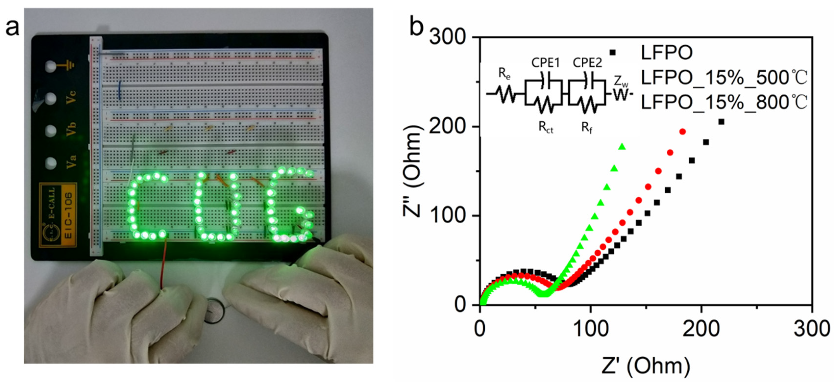
In Figure 5a, we can clearly see that a modified LFPO battery can light up 51 LED lights with CUG in the row. It is safe to say that the modified LFPO battery maintained high power, high capacity and high stability well during the charging/discharge process. Nyquist plots (Figure 5b) present a semicircle and a quasi-straight line, which are associated with the charge transfer resistance (Rct) and the impedance of Li+ diffusion in solid materials (Warburg impedance, Zw), respectively. The specific fitting data of EIS is presented in Table S2; the Rct of LFPO_15%_500 °C and LFPO_15%_800 °C are lower than those for LFPO and the Zw of LFPO_15%_500 °C and LFPO_15%_800 °C are higher than those for LFPO, indicating that the electronic transmission capability of the LFPO_15%_500 °C and LFPO_15%_800 °C electrodes are superior to LFPO. Based on the data obtained from the EIS test, the diffusion coefficient values of the lithium ions (D) can be calculated using the formula D = 0.5 (RT/AF2σwC)2, where R is the gas constant, T is the temperature, A is the area of the electrode surface, F is Faraday’s constant, σw is the Warburg factor and C is the molar concentration of Li ions [49]. The calculated lithium diffusion coefficient value for LFPO is 5.9 × 10⁻¹³ cm2·s−1, LFPO_15%_500 °C is 8.9 × 10⁻¹³ cm2·s−1 and LFPO_15%_800 °C is 3.36 × 10⁻¹² cm2·s−1. It is obvious that the lithium diffusion coefficient values of LFPO_15%_500 °C and LFPO_15%_800 °C are much higher than that of LFPO. The results show that the three-dimensional carbon-coated LFPO can improve the lithium ion diffusion rate, which can improve the specific capacity of LFPO.

4. Conclusions

In this work, three-dimensional carbon-coated LFPO was successfully fabricated through a facile water bath and a calcination method. The LFPO and CTAB formed a thin carbon layer on the LFPO surface by N2 sintering after the water bath, thereby enhancing the conductivity of the electrode. The electrochemical mechanisms of LFPO and modified LFPO were investigated. As a cathode material for LIBs, the modified LFPO exhibited excellent specific capacity (159.8 m·A·h·g−1 at 2 C), extraordinary rate performance (97.3 m·A·h·g−1 up to 5 C) and ultralong cycling stability (~84.2% maintained even after 500 cycles at 5 C). Such mesmerizing performances are ascribed to (i) the carbon layer covering the surface of LFPO nanoparticles, which enhances the integral conductivity, and (ii) the carbon layer on the surface of LFPO nanoparticles inhibiting the volume expansion between Li insertion/de-insertion processes. It can be seen that LFPO cathode can achieve good initial capacity and cycle life by carbon coating, which is cost-effective and easy to realize. This work suggests that using a carbon layer covering to modify electrode material is a promising strategy for obtaining high comprehensive performance electrode materials in the field of lithium cathode materials.

Supplementary Materials

The following are available online at https://www.mdpi.com/article/10.3390/coatings11091137/s1, Table S1: Specific capacity of different cathode materials for lithium-ion batteries, Table S2: Fitting data of LFPO, LFPO_15%_500 °C and LFPO_15%_800 °C equivalent circuit components, Table S3: The definitions of Nomenclature, Greek symbols, subscripts, superscripts, and acro-nyms, Table S4: The definitions of various abbreviations, Table S5: The various technical parameters of the work, Figure S1: Nitrogen adsorption-desorption isotherms of (a) LFPO _5%_500 °C, (b) LFPO_10%_500 °C, (c) LFPO_20%_500 °C, (d) LFPO _5%_800 °C, (e) LFPO_10%_800 °C and (f) LFPO_20%_800 °C, Figure S2: (a) TEM images of LFPO_15%_800 °C; (b) HRTEM images LFPO_15%_800 °C; (c) the corresponding SAED of LFPO_15%_800 °C, Figure S3: TG curve of LFPO, LFPO_15%_500 °C and LFPO_15%_800 °C, Figure S4: Cyclic voltammograms of LFPO_15%_800 °C at various scan rates from 0.1 to 1.0 mV s−1 in a voltage range of 2.5–4.2 V, Figure S5: Coulomb efficiency at all C rates, Figure S6: Cyclic performance of LFPO, LFPO_15%_500 °C and LFPO_15%_800 °C at 5C, Figure S7: (a) Cyclic performance of LFPO, LFPO_5%_500 °C, LFPO_10%_500 °C and LFPO_20%_500 °C at 2C; (b) Cy-clic performance of LFPO, LFPO_5%_800 °C, LFPO_10%_800 °C and LFPO_20%_800 °C at 2C, Figure S8: Galvanostatic charge and discharge curves of (a) LFPO and (b) LFPO_15%_500 °C at the current of 2C, Figure S9: Galvanostatic charge and discharge curves of (a) LFPO, (b) LFPO_15%_500 °C and (c) LFPO_15%_800 °C at the current of 5C, Figure S10: (a) Physical drawing of cyclic performance test, (b) Physical drawing of CV test and EIS test, (c) Physical drawing of the battery assembly.

Author Contributions

Data curation, C.W., X.Y., H.T. and S.J.; formal analysis, C.W., X.Y., H.T., S.J., Z.M., J.Z. and Y.D.; resources, X.W., D.C. and Y.D.; writing—review and editing, Y.D. All authors have read and agreed to the published version of the manuscript.

Funding

This work is supported by the National Natural Science Foundation of China (22004112, 51902296) and Foshan Xianhu Laboratory of the Advanced Energy Science and Technology Guangdong Laboratory (XHT2020-005).

Institutional Review Board Statement

Not applicable.

Informed Consent Statement

Not applicable.

Data Availability Statement

Not applicable.

Conflicts of Interest

The authors declare no conflict of interest.

References

  1. Lu, J.; Wu, T.P.; Amine, K. State-of-the-art characterization techniques for advanced lithium-ion batteries. Nat. Energy 2017, 2, 17011. [Google Scholar] [CrossRef]
  2. Sun, Y.; Liu, N.; Cui, Y. Promises and challenges of nanomaterials for lithium-based rechargeable batteries. Nat. Energy 2016, 1, 16071. [Google Scholar] [CrossRef]
  3. Tarascon, J.-M. Na-ion versus Li-ion batteries: Complementarity rather than competitiveness. Joule 2020, 4, 1616–1620. [Google Scholar] [CrossRef]
  4. Gao, X.-P.; Yang, H.-X. Multi-electron reaction materials for high energy density batteries. Energy Environ. Sci. 2010, 3, 174–189. [Google Scholar] [CrossRef]
  5. Tian, X.; Zhou, K. 3D printing of cellular materials for advanced electrochemical energy storage and conversion. Nanoscale 2020, 12, 7416–7432. [Google Scholar] [CrossRef]
  6. Haji Akhoundzadeh, M.; Panchal, S.; Samadani, E.; Raahemifar, K.; Fowler, M.; Fraser, R. Investigation and simulation of electric train utilizing hydrogen fuel cell and lithium-ion battery. Sustain. Energy Technol. Assess. 2021, 46, 101234. [Google Scholar]
  7. Duan, J.; Zhao, J.; Li, X.; Panchal, S.; Yuan, J.; Fraser, R.; Fowler, M. Modeling and analysis of heat dissipation for liquid cooling lithium-ion batteries. Energies 2021, 14, 4187. [Google Scholar] [CrossRef]
  8. Cano, Z.P.; Banham, D.; Ye, S.; Hintennach, A.; Lu, J.; Fowler, M.; Chen, Z. Batteries and fuel cells for emerging electric vehicle markets. Nat. Energy 2018, 3, 279–289. [Google Scholar] [CrossRef]
  9. Larcher, D.; Tarascon, J.M. Towards greener and more sustainable batteries for electrical energy storage. Nat. Chem. 2015, 7, 19–29. [Google Scholar] [CrossRef]
  10. Simon, P.; Gogotsi, Y. Perspectives for electrochemical capacitors and related devices. Nat. Mater. 2020, 19, 1151–1163. [Google Scholar] [CrossRef]
  11. Lu, J.; Chen, Z.; Ma, Z.; Pan, F.; Curtiss, L.A.; Amine, K. The role of nanotechnology in the development of battery materials for electric vehicles. Nat. Nanotechnol. 2016, 11, 1031–1038. [Google Scholar] [CrossRef] [PubMed]
  12. Islam, M.S.; Driscoll, D.J.; Fisher, C.A.J.; Slater, P.R. Atomic-Scale Investigation of defects, dopants, and lithium transport in the LiFePO4 olivine-type battery material. Chem. Mater. 2005, 17, 5085–5092. [Google Scholar] [CrossRef]
  13. Chen, G.; Song, X.; Richardson, T. Electron microscopy study of the LiFePO4 to FePO4 phase transition. J. Electrochem. Soc. 2006, 9, A295–A298. [Google Scholar]
  14. Arumugam, D.V.M.; Theivanayagam, M.G.; Manthiram, A. Comparison of microwave assisted solvothermal and hydrothermal syntheses of LiFePO4/C nanocomposite cathodes for lithium ion batteries. J. Phys. Chem. C 2008, 112, 14665–14671. [Google Scholar]
  15. Tran, M.-K.; DaCosta, A.; Mevawalla, A.; Panchal, S.; Fowler, M. Comparative study of equivalent circuit models performance in four common lithium-ion batteries: LFP, NMC, LMO, NCA. Batteries 2021, 7, 51. [Google Scholar] [CrossRef]
  16. Xu, L.; Tang, S.; Cheng, Y.; Wang, K.; Liang, J.; Liu, C.; Cao, Y.-C.; Wei, F.; Mai, L. Interfaces in solid-state lithium batteries. Joule 2018, 2, 1991–2015. [Google Scholar] [CrossRef] [Green Version]
  17. Zhou, L.; Zhang, K.; Hu, Z.; Tao, Z.; Mai, L.; Kang, Y.-M.; Chou, S.-L.; Chen, J. Recent developments on and prospects for electrode materials with hierarchical structures for lithium-ion batteries. Adv. Energy Mater. 2017, 8, 1701415. [Google Scholar] [CrossRef]
  18. Wang, L.; Dong, Y.; Zhao, K.; Luo, W.; Li, S.; Zhou, L.; Mai, L. Interconnected LiCuVO4 networks with in situ Cu generation as high-performance lithium-ion battery anode. Phys. Chem. Chem. Phys. 2017, 19, 13341–13347. [Google Scholar] [CrossRef]
  19. Dhanabalan, A.; Wang, C. Lithium-ion batteries: Three-dimensional porous core-shell Sn@carbon composite anodes for high-performance lithium-ion battery applications. Adv. Energy Mater. 2012, 2, 174. [Google Scholar]
  20. Meng, J.; Liu, X.; Niu, C.; Pang, Q.; Li, J.; Liu, F.; Liu, Z.; Mai, L. Advances in metal–organic framework coatings: Versatile synthesis and broad applications. Chem. Soc. Rev. 2020, 49, 3142–3186. [Google Scholar] [CrossRef]
  21. Meng, J.; He, Q.; Xu, L.; Zhang, X.; Liu, F.; Wang, X.; Li, Q.; Xu, X.; Zhang, G.; Niu, C.; et al. Identification of phase control of carbon-confined Nb2O5 nanoparticles toward high-performance lithium storage. Adv. Energy Mater. 2019, 9, 1802695. [Google Scholar] [CrossRef]
  22. Meng, J.; Liu, X.; Li, J.; Li, Q.; Zhao, C.; Xu, L.; Wang, X.; Liu, F.; Yang, W.; Xu, X.; et al. General oriented synthesis of precise carbon-confined nanostructures by low-pressure vapor superassembly and controlled pyrolysis. Nano Lett. 2017, 17, 7773–7781. [Google Scholar] [CrossRef]
  23. Wang, S.; Fang, Y.; Wang, X.; Lou, X.W. Hierarchical microboxes constructed by SnS nanoplates coated with nitrogen-doped carbon for efficient sodium storage. Angew. Chem. Int. Edit. 2019, 58, 760–763. [Google Scholar] [CrossRef]
  24. Sarigul, G.; Chamorro-Mena, I.; Linares, N.; García-Martínez, J.; Serrano, E. Hybrid amino acid-TiO2 materials with tuneable crystalline structure and morphology for photocatalytic applications. Adv. Sustain. Syst. 2021, 2100076. [Google Scholar] [CrossRef]
  25. Zhou, L.; Zhuang, Z.; Zhao, H.; Lin, M.; Zhao, D.; Mai, L. Intricate hollow structures: Controlled synthesis and applications in energy storage and conversion. Adv. Mater. 2017, 29, 1602914. [Google Scholar] [CrossRef] [PubMed]
  26. Cheng, Z.; Liu, M.; Ganapathy, S.; Li, C.; Li, Z.; Zhang, X.; He, P.; Zhou, H.; Wagemaker, M. Revealing the impact of space-charge layers on the Li-ion transport in all-solid-state batteries. Joule 2020, 4, 1311–1323. [Google Scholar] [CrossRef]
  27. Yang, J.; Wang, J.; Wang, D.; Li, X.; Geng, D.; Liang, G.; Gauthier, M.; Li, R.; Sun, X. 3D porous LiFePO4/graphene hybrid cathodes with enhanced performance for Li-ion batteries. J. Power Sources 2012, 208, 340–344. [Google Scholar] [CrossRef]
  28. Shi, Y.; Chou, S.-L.; Wang, J.-Z.; Wexler, D.; Li, H.-J.; Liu, H.-K.; Wu, Y. Graphene wrapped LiFePO4/C composites as cathode materials for Li-ion batteries with enhanced rate capability. J. Mater. Chem. 2012, 22, 16465–16470. [Google Scholar] [CrossRef] [Green Version]
  29. Zhou, X.; Wang, F.; Zhu, Y.; Liu, Z. Graphene modified LiFePO4 cathode materials for high power lithium ion batteries. J. Mater. Chem. 2011, 21, 3353–3358. [Google Scholar] [CrossRef]
  30. Kim, H.; Kim, S.-W.; Hong, J.; Lim, H.-D.; Kim, H.S.; Yoo, J.-K.; Kang, K. Graphene-based hybrid electrode material for high-power lithium-ion batteries. J. Electrochem. Soc. 2011, 158, A930–A935. [Google Scholar] [CrossRef]
  31. Lung-Hao Hu, B.; Wu, F.-Y.; Lin, C.-T.; Khlobystov, A.N.; Li, L.-J. Graphene-modified LiFePO4 cathode for lithium ion battery beyond theoretical capacity. Nat. Commun. 2013, 4, 1687. [Google Scholar] [CrossRef] [Green Version]
  32. Zhang, K.; Lee, J.T.; Li, P.; Kang, B.; Kim, J.H.; Yi, G.R.; Park, J.H. Conformal coating strategy comprising N-doped carbon and conventional graphene for achieving ultrahigh power and cyclability of LiFePO4. Nano Lett. 2015, 15, 6756–6763. [Google Scholar] [CrossRef] [PubMed]
  33. Lu, Z.; Liu, N.; Lee, H.-W.; Zhao, J.; Li, W.; Li, Y.; Cui, Y. Nonfilling carbon coating of porous silicon micrometer-sized particles for high-performance lithium battery anodes. ACS Nano 2015, 9, 2540–2547. [Google Scholar] [CrossRef]
  34. Ji, Q.; Gao, X.; Zhang, Q.; Jin, L.; Wang, D.; Xia, Y.; Yin, S.; Xia, S.; Hohn, N.; Zuo, X.; et al. Dental resin monomer enables unique NbO2/carbon lithium-ion battery negative electrode with exceptional performance. Adv. Funct. Mater. 2019, 29, 1904961. [Google Scholar] [CrossRef] [Green Version]
  35. Zhou, X.; Dai, Z.; Liu, S.; Bao, J.; Guo, Y.-G. Ultra-uniform SnOx/carbon nanohybrids toward advanced lithium-ion battery anodes. Adv. Mater. 2014, 26, 3943–3949. [Google Scholar] [CrossRef]
  36. An, Q.; Xiong, F.; Wei, Q.; Sheng, J.; He, L.; Ma, D.; Yao, Y.; Mai, L. Nanoflake-assembled hierarchical Na3V2(PO4)3/C microflowers: Superior Li storage performance and insertion/extraction mechanism. Adv. Energy Mater. 2015, 5, 1401963. [Google Scholar] [CrossRef]
  37. Chen, Z.; Dahn, J.R. Improving the capacity retention of LiCoO2 cycled to 4.5 V by heat-treatment. Electrochem. Solid-State Lett. 2004, 7, A11–A14. [Google Scholar] [CrossRef]
  38. Shim, J.-H.; Lee, K.-S.; Missyul, A.; Lee, J.; Linn, B.; Lee, E.C.; Lee, S. Characterization of spinel LixCo2O4-coated LiCoO2 prepared with post-thermal treatment as a cathode material for lithium ion batteries. Chem. Mater. 2015, 27, 3273–3279. [Google Scholar] [CrossRef]
  39. Kalluri, S.; Yoon, M.; Jo, M.; Park, S.; Myeong, S.; Kim, J.; Dou, S.X.; Guo, Z.; Cho, J. Surface engineering strategies of layered LiCoO2 cathode material to realize high-energy and high-voltage Li-ion cells. Adv. Energy Mater. 2017, 7, 601507. [Google Scholar]
  40. Wu, Y.; Wen, Z.; Li, J. Hierarchical carbon-coated LiFePO4 nanoplate microspheres with high electrochemical performance for Li-ion batteries. Adv. Mater. 2011, 23, 1126–1129. [Google Scholar] [CrossRef]
  41. Liu, Y.; Gu, J.; Zhang, J.; Yu, F.; Dong, L.; Nie, N.; Li, W. Metal organic frameworks derived porous lithium iron phosphate with continuous nitrogen-doped carbon networks for lithium ion batteries. J. Power Sources 2016, 304, 42–50. [Google Scholar] [CrossRef]
  42. Zhang, Y.; Huang, Y.; Wang, X.; Guo, Y.; Jia, D.; Tang, X. Improved electrochemical performance of lithium iron phosphate in situ coated with hierarchical porous nitrogen-doped graphene-like membrane. J. Power Sources 2016, 305, 122–127. [Google Scholar] [CrossRef]
  43. Yang, J.; Wang, J.; Tang, Y.; Wang, D.; Li, X.; Hu, Y.; Li, R.; Liang, G.; Sham, T.-K.; Sun, X. LiFePO4–graphene as a superior cathode material for rechargeable lithium batteries: Impact of stacked graphene and unfolded graphene. Energy Environ. Sci. 2013, 6, 1521. [Google Scholar] [CrossRef]
  44. Belharouak, I.; Johnson, C.; Amine, K. Synthesis and electrochemical analysis of vapor-deposited carbon-coated LiFePO4. Electrochem. Commun. 2005, 7, 983–988. [Google Scholar] [CrossRef]
  45. Lou, X.; Zhang, Y. Synthesis of LiFePO4/C cathode materials with both high-rate capability and high tap density for lithium-ion batteries. J. Mater. Chem. 2011, 21, 4156. [Google Scholar] [CrossRef]
  46. Dong, Y.; Li, S.; Zhao, K.; Han, C.; Chen, W.; Wang, B.; Wang, L.; Xu, B.; Wei, Q.; Zhang, L.; et al. Hierarchical zigzag Na1.25V3O8 nanowires with topotactically encoded superior performance for sodium-ion battery cathodes. Energy Environ. Sci. 2015, 8, 1267–1275. [Google Scholar] [CrossRef]
  47. Pei, C.; Yin, Y.; Liao, X.; Xiong, F.; An, Q.; Jin, M.; Zhao, Y.; Mai, L. Structural properties and electrochemical performance of different polymorphs of Nb2O5 in magnesium-based batteries. J. Energy Chem. 2021, 58, 586–592. [Google Scholar] [CrossRef]
  48. Dong, Y.; Xu, J.; Chen, M.; Guo, Y.; Zhou, G.; Li, N.; Zhou, S.; Wong, C.-P. Self-assembled NaV6O15 flower-like microstructures for high-capacity and long-life sodium-ion battery cathode. Nano Energy 2020, 68, 104357. [Google Scholar] [CrossRef]
  49. Dong, Y.; Xu, X.; Li, S.; Han, C.; Zhao, K.; Zhang, L.; Niu, C.; Huang, Z.; Mai, L. Inhibiting effect of Na+ pre-intercalation in MoO3 nanobelts with enhanced electrochemical performance. Nano Energy 2015, 15, 145–152. [Google Scholar] [CrossRef]
Figure 1. (a) XRD patterns of LFPO, LFPO_15%_500 °C and LFPO_15%_800 °C, (b) Schematic illustrations of the crystal structure of LiFePO4 (purple ball: Li, pink ball: O, blue octahedron: FeO6 and yellow tetrahedron: PO4).
Coatings 11 01137 g001
Figure 2. FESEM images of (a) LFPO, (b) LFPO_15%_500 °C and (c) LFPO_15%_800 °C; Elemental mapping images of (df) LFPO_15%_800 °C; Nitrogen adsorption–desorption isotherms of (g) LFPO, (h) LFPO_15%_500 °C and (i) LFPO_15%_800 °C.
Coatings 11 01137 g002
Figure 3. TEM images of (a) LFPO, (b) LFPO_15%_500 °C, (c) LFPO_15%_800 °C; HRTEM images (d) LFPO, (e) LFPO_15%_500 °C and (f) LFPO_15%_800 °C; the inset is the corresponding SAED.
Coatings 11 01137 g003
Figure 4. (a) Cycle voltammograms at a scan rate of 0.1 mV·s−1 in a voltage range of 2.5 to 4.2 V. (b) Cycle performance of LFPO, LFPO_15%_500 °C and LFPO_15%_800 °C at 2 C. (c) Galvanostatic charge and discharge curves of LFPO_15%_800 °C at the current of 2 C. (d) Rate performance of LFPO_15%_800 °C at rates of 0.1, 0.2, 0.5, 1, 2, 5 C and back to 0.1 C. (e) Cycling performance of LFPO, LFPO_15%_500 °C and LFPO_15%_800 °C measured at a current density of 5 C.
Coatings 11 01137 g004
Figure 5. (a) Demonstration experiment of LFPO battery lighting the word “CUG” in LED. (b) EIS of LFPO, LFPO_15%_500 °C and LFPO_15%_800 °C at OCV stage in the frequency range of 100 kHz to 0.01 Hz.
Coatings 11 01137 g005
Publisher’s Note: MDPI stays neutral with regard to jurisdictional claims in published maps and institutional affiliations.