Article

Analysis of Heat Transfer Characteristics of a Heat Exchanger Based on a Lattice Filling

1
State Key Laboratory for Manufacturing System Engineering, Xi’an Jiaotong University, Xi’an 710049, China
2
Avic Xi’an Aero-Engine (Group) Ltd., Xi’an 710100, China
*
Author to whom correspondence should be addressed.
Coatings 2021, 11(9), 1089; https://doi.org/10.3390/coatings11091089
Submission received: 3 August 2021 / Revised: 23 August 2021 / Accepted: 2 September 2021 / Published: 8 September 2021

Abstract

:
In response to the heat load requirements of the high-thrust liquid rocket engine, a light-weight lattice structure is used to fill traditional a heat exchanger. A parameterized model library of the lattice structure is established, and the relative density of the lattice structure is adjusted by changing the unit cell structure parameters to obtain different filling structures. A comprehensive comparison of heat exchangers with different filling structures performed in terms of weight, heat transfer efficiency, and turbulence intensity. Using the finite difference method, the numerical calculation of the non-steady heat–fluid–solid coupling conjugate heat transfer of the eight-lattice structure is performed, and the dynamic heat transfer process between the lattice structure and liquid oxygen is simulated using the VOF model and the SST k-ω model. The results show that the pressure of the fluid in the heat exchanger increases with increasing relative density, leading to a high outlet temperature and greatly increasing the outlet velocity. The support trusses close to the wall obviously hinder the flow of liquid oxygen, resulting in a sudden change in the flow rate behind the support trusses, driving the high-temperature fluid at the bottom to move upwards. The direction of the support trusses and the unit cell porosity have a greater impact on the liquid oxygen flow rate, which in turn affects the flow and heat transfer performance of the heat exchanger. In consideration of the heat load requirements of the heat exchanger, star-type lattices are used to fill the heat exchanger. When the flow is fully developed, the volume ratio of the heated fluid is 85.60%, and the outlet temperature is 390 K, which meets the design requirements.

1. Introduction

The heat exchanger is one of the key components of liquid rocket engines. Its main function is to allow full heat exchange between liquid oxygen and high-temperature fuel gas, resulting in the evaporation of the liquid oxygen into gas oxygen, which then enters the storage tank of the rocket oxidizer under the effects of pressure to provide a stable supply of propellant for the engine; therefore, the efficiency of the heat exchanger is one of the key factors affecting the performance of the engine [1,2,3]. At present, the structure of heat exchangers is typically designed in the form of an array-distributed rectangular milling groove structure or a spiral groove structure [4,5], which is formed by tailor-welding a split structure [6,7]. The uneven flow of the molten pool during the welding process causes the channel to be blocked, and the residual stress after cooling is likely to cause deformation or even cracking, making the engine to function inefficiently. When a heat exchanger with a milling groove structure is used, the length of the heat exchanger must be increased if the heat exchange efficiency is to be improved. The increase in length is accompanied by an increase in the volume, weight and heating time of the heat exchanger, making it difficult to meet the requirements for use in new engines.
At present, compact heat exchanger structures made using new materials such as foam metal and porous lattices have begun to replace the traditional milling groove structure, and are being applied in the aviation industry [8,9,10]. Hossain, Smz et al. [11] used double pipes to increase the heat transfer surface area, supporting three different media working together at the same time. Compared with the shell and tube structure, the efficiency of this structure represented an increase by about 60%. Although the structure exhibits improved thermal efficiency, its stability needs further study due to the lack of bearing parts that offer the same capacity as the support of ribs. A, Punnoose Abraham et al. [12] manufactured heat exchangers with different numbers of fins. On the basis of flow heat transfer analysis, it was found that the heat transfer coefficient and Reynolds number on the air side were independent of the number of fins. Li, K et al. [13,14] studied the heat transfer characteristics and stress distribution of heat exchangers with different fin lengths, numbers and other geometric parameters under low-temperature conditions. The results showed that the stress was mainly concentrated in the splicing areas, such as welds. Kou et al. [15,16] used CFD to simulate the heat transfer performance of several microchannel heat exchangers with different channel heights and widths but the same channel surface area, and found that there was a certain height and width value that resulted in an optimal heat transfer effect. Romvonge et al. [17] conducted a numerical study on a square-section heat exchanger with two angle baffles (45° and 90°), and the results showed that the heat exchanger with a baffle angle of 45° had better heat transfer performance. Goldstein L et al. [18,19] experimentally studied the heat transfer enhancement effect of corrugated fins on baffle heat exchangers under different flow conditions, and the results showed that the heat transfer enhancement of fins with laminar flow was stronger than that obtained with turbulent flow. Selimefendigil F et al. [20] numerically calculated the flow downstream of the step surface when the fluid passed through the elliptic shaped porous object, and found that the larger the aspect ratio, the lower the heat transfer rate. Addition of hybrid nanoparticles to the fluid resulted in a further enhancement of 28.4% to the average heat transfer. The lattice structure is a new type of ultra-light ordered porous material, which has the characteristics of small volume, large heat transfer area and high heat transfer efficiency. Using the lattice structure as the filling material for the inner fluid causes the heat exchanger to have obvious structural characteristics, which can not only reduce the weight of the heat exchanger, but also increase the heat exchange area. Due to the blocking effect of the lattice support truss, the flow direction of the fluid in the flow channel changes continuously. When the flow enters a quasi-steady state, the vortex in the inner fluid drives the fluid to form flow circulation areas of different sizes, forcing the heat transfer to increase. In combination with additive manufacturing, the complexity of the inner fluid filling structure is greatly improved.
At present, lattice structures are mainly used for lightweight design, and the research on forced heat transfer with it as a filling structure is still in its infancy. There is a lack of theoretical and technical systems suitable for lattice structure selection and heat transfer efficiency evaluation, as well as flow heat and mass transfer mechanisms under multi-field coupling. It is still necessary to conduct in-depth research on the macroscopic characteristics and heat transfer characteristics of lattice structures. This article selects the internal filling structure of the heat exchanger from the aspects of model design, load-bearing performance and heat transfer characteristics. The multi-flow model is used to calculate the dynamic heat transfer process of liquid oxygen in heat exchangers with different flow channel structures, and the internal mechanism of using a lattice structure to enhance heat transfer efficiency is revealed.

2. Establishment of a Parametric Model of the Unit Cell Lattice Structure

The structure of the lightweight porous lattice structure is similar to the molecular configuration. The nodes and connecting truss are used form a periodic topological structure. Lattice structures composed of different cell structures possess vastly different mechanical properties. Common three-dimensional lattice structures include the pyramid type, tetrahedron type, X type, and so on [21,22,23]. Figure 1 shows the local structure of the star type lattice cell. Each unit cell model consists of eight trusses with circular cross-sections. The parameters that determine the geometric model of the lattice structure mainly include: bounding box side length, truss section radius, truss space inclination angle, end closed form.
To make the macroscopic parts formed by the filling of the lightweight lattice structure have the same quality and shape and position accuracy, it is necessary to ensure that the lattice structures have the same relative density, and then to evaluate their mechanical properties and formability. The relative density can be expressed as:
ρ = π r 2 L t V c e l l
where r is the cross-sectional radius of the cell truss, Lt is the total length of the cell truss, and Vcell is the bounding box volume.
In this paper, we designed a cell lattice structure derived from a hexahedral microstructure, and established the logical control relationship between the lattice cell and the three-dimensional model, finally realizing the automatic selection of the characteristic parameters of the cell structure through a secondary development program. The design process mainly included the following steps:
  • According to the structural characteristics of the hexahedron, the key parameters such as the side length, diagonal length, body center coordinates and face center coordinates of each cell are calculated and stored in the array.
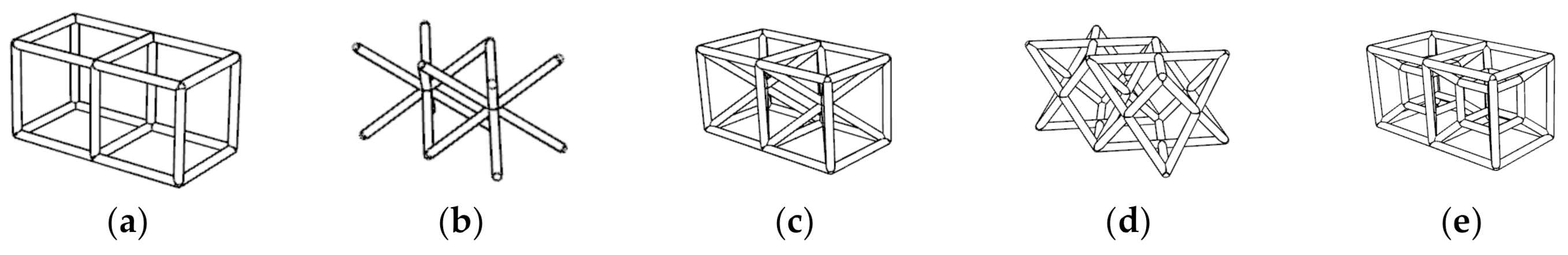
  • The cell structure is initialized according to the characteristics of the wireframe structure in Figure 2, and the truss length data are retrieved from the database.
  • The length, width and height of the bounding box are changed to obtain the distribution of trusses in different spatial orientations.
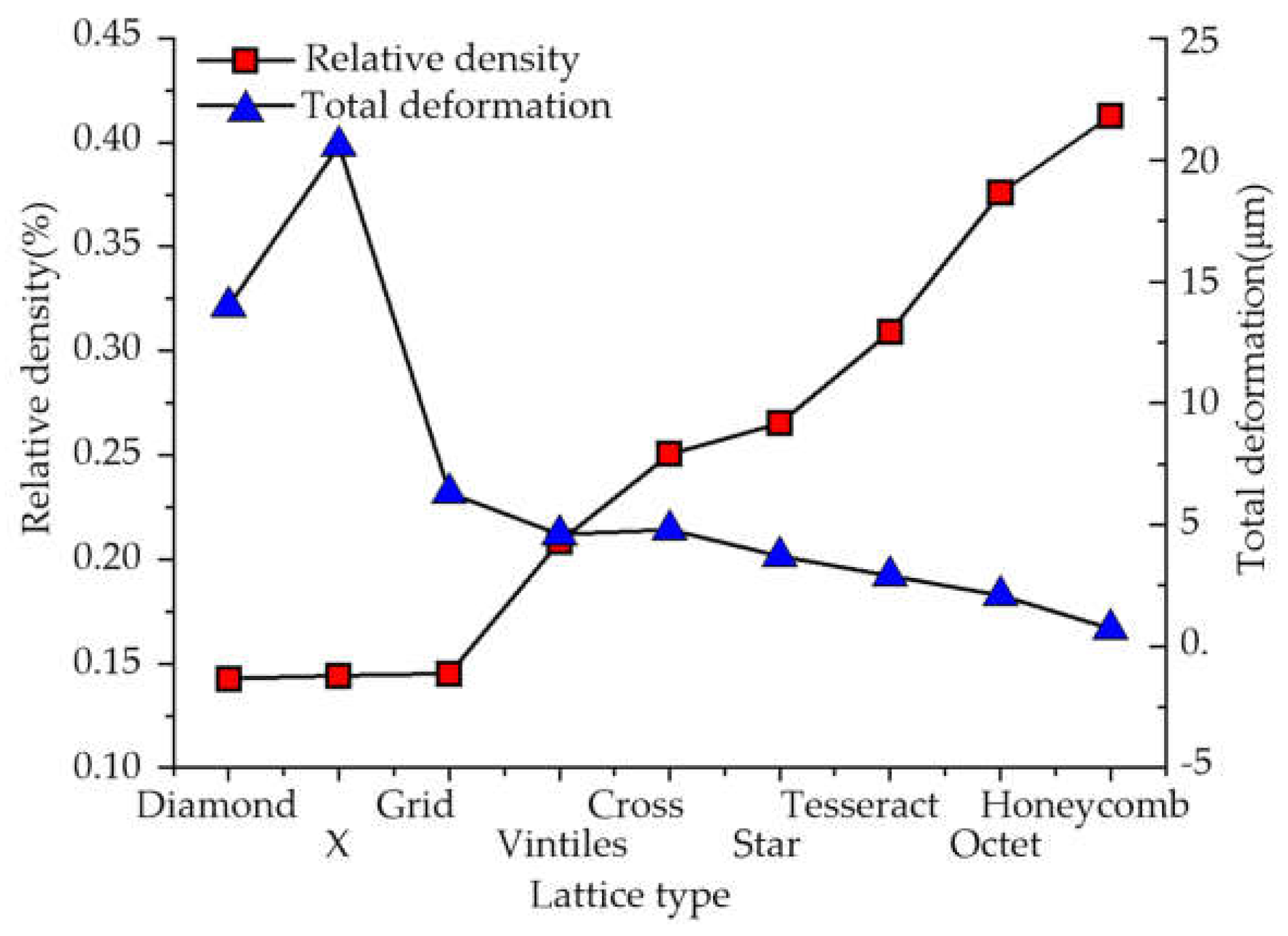
  • The radius of the dot matrix truss is changed to achieve continuous adjustment of relative density.
  • Combined with the numerical results of different structures, the characteristic parameters and mechanical properties of lattice structure are stored in the database for comparison and selection with the subsequent structural data.
According to the design requirements of the parameterized model of the lattice structure, the value range of the radius r of the support rod is set to 0.2–0.55 mm, and the length of the characteristic hexahedron is 2 mm. When the lattice type is unchanged, the compressive capacity of the lattice structure increases with the increase of the radius of the support rod. To further analyze the load-bearing performance of different lattice structures, the radius of the support rod was kept constant, and different relative densities were obtained by changing the lattice type. The eight lattice structures in Figure 2 were subjected to finite element analysis with a compressive load of 200 N, and all lattice types were restrained with a fixed bottom surface. The relative density of each lattice structure increases with the increase of the support rod radius, and the compression deformation decreases with the increase of the support rod radius except for the X-shaped lattice structure, as shown in Figure 3. The X-shaped lattice is directly crushed under a pressure of 200 N, resulting in greater deformation. The diamond type lattice has the smallest deformation and can withstand larger compressive loads.

3. Analysis of Fluid–Solid Coupling Heat Transfer

To study the influence of different lattice structures on heat transfer performance, thermal structure response calculation and flow heat transfer analysis were carried out, and the influence of unit cell parameters on lattice heat transfer performance was analyzed.

3.1. Calculation Model and Boundary Conditions

Since the distance between the inner and outer walls of the engine heat exchanger is 12 mm, the bounding box of the unit cell lattice structure has a side length of 12 mm, and the support truss radius is 0.5 mm. The lattice type is shown in Figure 3. Assuming that the number of lattices arranged in the height and width directions is 1 and 10, respectively, the cross-sectional size of the heat exchanger is 1440 mm2. Therefore, the hydraulic diameter Dh of the inner fluid is:
D h = 4 A C = 2 W H W + H
The Reynolds number Re is:
R e = ρ o m s D h μ
where ρo is the density of liquid oxygen, ms is the mass flow, and μ is the dynamic viscosity of the liquid oxygen.
The k-ω STT two-equation model proposed by Menter FR is used to calculate the flow and heat transfer of liquid oxygen in the lattice structure [24]. This hybrid model uses the original k-ω calculation model near the wall, considering the restriction and shear flow of liquid oxygen on the wall, and approximates the k-ε calculation model in the area away from the wall, which can reflect the local turbulence. The k equation and ω equation, as well as the calculation of eddy viscosity coefficient, are as follows:
( ρ o k ) t = P k ρ o k 3 / 2 l k ω + x i [ ( μ + μ t σ k ) k x i ]
( ρ o ω ) t = α 2 ω k P ω β 2 ρ o ω 2 + x i [ ( μ + μ t σ ω 2 ) ω x i ] + 2 ρ o ( 1 F 1 ) σ ω 2 1 ω k x i ω x i
μ t = ρ 0 a 1 k max ( a 1 ω , Ω F 2 )
where Pω and Pk are turbulence generation terms, F1 and F2 are mixing functions, α2, β2, σk, and σω2 are empirical coefficients, μt is the eddy viscosity coefficient, a1 is a constant coefficient, and Ω is the vorticity.
The internal geometry of the lattice structure is complex, and in order to improve the calculation efficiency, the following assumptions are made for the model: the liquid oxygen in the inner fluid is a viscous incompressible fluid. The numerical calculation process satisfies the three laws of conservation of mass, conservation of energy and conservation of momentum. To accurately capture the flow details of liquid oxygen, the VOF method is used to track the gas–liquid free interface. When the fluid volume fraction in the grid is 1, the fluid is liquid, and less than 1 means the fluid is gaseous.
The heat transfer boundary conditions of the wall are as follows:
Q = m s c o ( T o u t T i n )
where mS is the mass flow rate, CO is the constant pressure specific heat of liquid oxygen, tout and tin are the inlet boundary temperature and outlet boundary temperature, respectively.
Since the lattice structure is periodically arranged in the three-dimensional space, in order to improve the calculation efficiency and the quality of the grid division after the extraction of the inner fluid, the number of repetitions of each lattice cell in the x and y directions is two. By setting the symmetry plane, the final model consists of two lattice cells, as shown in Figure 4.
ANSYS Fluent is used to analyze the transient heat transfer process of liquid oxygen flowing through the lattice structure. Take the grid-type lattice as an example; the inner fluid is shown in Figure 5. SDCEF is the pressure outlet, the outlet temperature is 380 K, and the opposite surface is the mass flow inlet. The flow direction is AD, the mass flow rate is 0.02 kg/s, and the inlet temperature is 114 K. SABCD and its opposite surface are symmetrical surfaces, SGADF is the cold end wall surface with a temperature of 300 K, and the opposite surface is the hot end wall surface with a temperature of 750 K. The semi-implicit pressure–velocity coupling method is used to discretize the control equations. At the same time, the second-order upwind model is used to discretize the values before and after the grid nodes and transfer them to the next node for solution. Because the lattice structure is more complicated, the initial pressure field and velocity field are calculated by the hybrid initialization method. When the calculation fails to converge, a steady-state calculation of about 10 steps is performed before the transient analysis to maintain a stable value for the initial temperature, pressure, and velocity. Yu Z Q et al. [25,26,27] conducted grid independence tests on various lattice structures composed of cylindrical support rods and found that 1.5 million grids are enough for the mesh independence. Therefore, this paper uses tetrahedral elements to mesh the fluid area. The grid size is set to 3.58 × 10⁻⁵ m, and the Curvature Normal Angle is defined as 14. The 10 layers of boundary layer grid is added near the lattice wall, and the height of the first layer grid is 1 × 10⁻⁵ m. The grid number of the final grid lattice runner is 1.83 million, as shown in Figure 5.

3.2. Discussion

Yan H et al. [28] studied the flow and heat transfer characteristics of the X-shaped lattice structure. They found that vortex in different directions would impact the surface of the lattice structure to enhance the local heat transfer effect. The same flow characteristics are shown in Figure 6. However, it can be seen from Figure 3 that the X-type lattice has poor load-bearing characteristics. Considering the requirements of force and load, a star-type lattice with longitudinal support rods should be selected. When the liquid oxygen passes through the star lattice, the hot end temperature remains constant throughout the calculation process. Due to the different lattice structure, especially the change in the position distribution of the support trusses, the instantaneous velocity and flow direction of the liquid oxygen passing through the support trusses will change suddenly, driving the fluid near the hot end to flow upwards and increasing the liquid oxygen temperature in the center of the fluid.
From Figure 6a,b, it can be seen that the support trusses have an obvious obstructive effect on the fluid, and the fluid separates around the support trusses, forming a circular cylindrical flow behind it, which drives the high-temperature liquid at the bottom to move upwards, causing the temperature at the bottom of the fluid to conduct upwards, and the temperature behind the support trusses is significantly higher than in other areas. After 0.45 s, the flow reaches a quasi-steady state, as shown in Figure 6c,g. The temperature conduction distribution state at z = 0.006 m does not change much before and after the model enters the quasi-steady state, because there are no support trusses at the center of the fluid, and the heat is mainly transferred upwards in the form of conduction. There are support rods in the y and z directions, and the heat is transferred upwards by flow and conduction. Figure 6g presents the isovolume of fluid with a temperature less than 120 K. Since the temperature of the hot end (T = 750 K) is greater than the temperature of the cold end (T = 300 K), the bottom temperature of the high-temperature fluid is greater than that of the top, and the isovolume shows an asymmetric distribution that is large on the top and small on the bottom. According to the statistical results, it is found that the volume of the isovolume with a temperature greater than 120 K is 2.5523 × 10⁻⁶ m³, and the volume of the entire fluid is 3.56373 × 10⁻⁶ m³, so the proportion of the heated fluid is 28.38%. In the same way, the isovolumes of the remaining four types of lattice structure are shown in Figure 7.
Figure 8 shows the volume ratio and relative density of the heated fluid in each lattice structure. Since the vortex intensities generated by the fluid passing through the cross type lattice and the tesseract type lattice are the lowest, the temperature increase of the fluid is the smallest. Considering the strength of the lattice structure and the temperature conductivity, the star type lattice cell is finally selected as the basic filling structure of the heat exchanger.

3.3. Analysis of Thermal Structure Response of Star Type Lattice Cell

Assuming that the lattice structure uses air as the medium for heat transfer before liquid oxygen is injected, the heat transfer form of the heat exchanger includes three types: heat conduction, convection and heat radiation. The material of the lattice structure is stainless steel, and the geometric size is 2 mm × 2 mm × 2 mm, as shown in Figure 9. The temperature constraint at the bottom of the panel is 750 K, and at the top of the panel is 300 K.
It can be seen from the figure that under the action of uniform temperature load, the temperature will continuously penetrate from the hot end to the cold end until it reaches a stable state, and along the temperature transfer direction, the temperature field of each lattice cell is uniformly distributed. When only the bottom surface is temperature constrained, the heat transfer characteristics of the two structures show obvious differences. The lowest temperature after the star type lattice reaches the steady state is 461.98 K, and the lowest temperature after the X type lattice reaches the steady state is 741.55 K. The main reason for this is that the relative density of the star type lattice is 1.6 times that of the X type lattice, so more heat is transferred to the cold end in the form of heat conduction.

4. Model Design and Flow Heat Transfer Analysis of Heat Exchanger

4.1. Model Design

To increase the liquid oxygen temperature at the outlet of the heat exchanger, baffles and lattice structures are respectively designed in the inner flow area to form a relatively complicated internal flow channel. The heat exchanger is filled with a star-shaped lattice structure with a better heat transfer effect. The specific structure is shown in Figure 10. The red area in the figure is the high-temperature steam, and the cavity area between the heat exchanger skin and the high-temperature steam is the lattice flow channel. The diameter of the inner wall of the fluid is 34 mm, the diameter of the outer wall is 46 mm, the diameter of the mass inlet and the pressure outlet is 4 mm (the hydraulic diameter d is 4 mm), and the diameter of each lattice support truss is 1 mm.

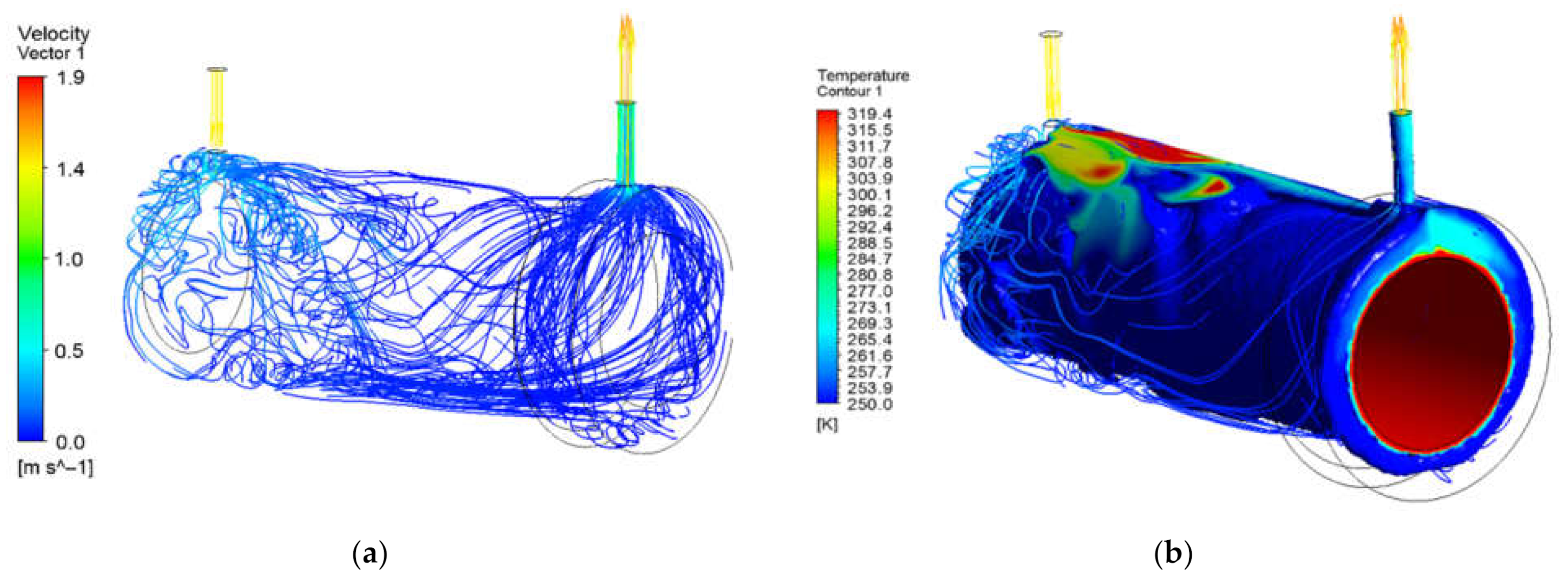
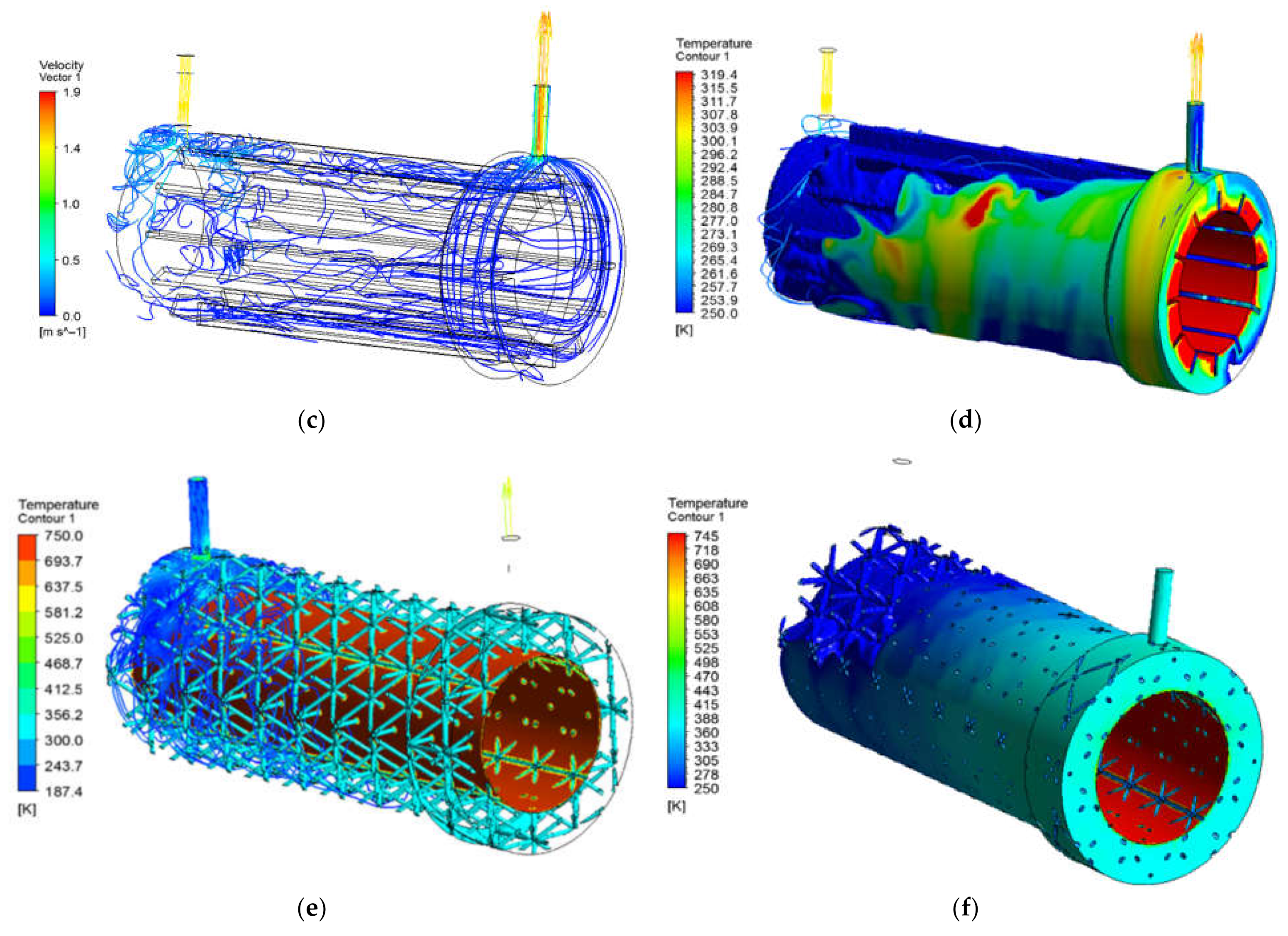
4.2. Numerical Calculation and Discussion

According to the use requirements of the heat exchanger, the liquid oxygen flows into the heat exchanger from the inlet at a rate of 20 g/s to be fully heated and then sent into the combustion chamber through the outlet. When the temperature of the liquid oxygen flowing out of the outlet is higher, the energy required to vaporize the liquid oxygen during combustion is lower. Therefore, the three heat exchanger structures are selected with the highest outlet temperature and the largest heating fluid volume as the selection objective. According to Equations (2) and (3), the Reynolds number of the liquid oxygen at the inlet is far greater than 2000. Therefore, the steady-state solution method is adopted, and the turbulence model adopted is the k-ω model. To ensure the calculation accuracy, the mesh size is set to 3.58 × 10⁻⁵ m.
It can be seen from Figure 11a,b that when there is no baffle or lattice structure in the flow channel, the liquid oxygen is injected from the inlet at a high speed and then moves downward along the wall surface, and then flows along the bottom to the outlet direction. When the flow front reaches the wall surface, a part of the fluid flows upward under the action of thermal buoyancy and surface tension, and finally ejects outward at a speed of about 1.4 m/s under the action of fluid pressure (3354 Pa); another part of the liquid flows back and is brought to the vicinity of the outlet after colliding with the wall, and is ejected along with the previously rising fluid. As the backflow reverses the direction of flow, the speed gradually decreases, and the temperature increases continuously. The model shown in Figure 11c,d is based on the model shown in Figure 11a,b, with 12 1.25-mm-thick baffles added in the direction of the bus bar on the inner wall of the heat exchanger. It can be seen from the streamline diagram that the flow of liquid oxygen is obviously restricted, and there is almost no convection in the fluid between the baffles, and it mainly flows along the baffle toward the outlet. When the flow front reaches the wall near the outlet, it flows upward along the gap between the baffle and the top of the inner fluid under pressure. The temperature distribution in Figure 11d shows the upward flow and heating of liquid oxygen. Due to the restriction of the baffle, it is difficult for the low-temperature fluid under the heat exchanger to move upwards. Under the long-term action of the high-temperature steam, the volume fraction of the high-temperature fluid increases significantly, as shown in Table 1. The uppermost baffle isolates a flow channel between the inlet and the outlet, and quickly transports the cryogenic fluid from the inlet to the outlet. Therefore, among the three structures, the outlet temperature of the heat exchanger with the baffle is the lowest.
On the basis of the above two structures, Figure 11e,f analyze the flow and heat transfer of liquid oxygen in the heat exchanger with the lattice filling. When the fluid passes through the lattice structure, there will be many small-scale disturbances, forming an uneven velocity field, which enhances the flow and heat transfer between different lattice areas. It can be seen from Table 1 that the outlet temperature of the heat exchanger with the lattice filling structure is the highest, and the volume ratio of the high-temperature fluid inside the fluid is much higher than that of the other two structures.

5. Conclusions

To increase the outlet steam temperature of the engine heat exchanger, the vof method is used to track the gas–liquid interface, and the nonlinear changes in the physical parameters of the wall are considered in the calculation process, and then the flow heat transfer analysis results are calculated by thermal indirect structure coupling. The results show:
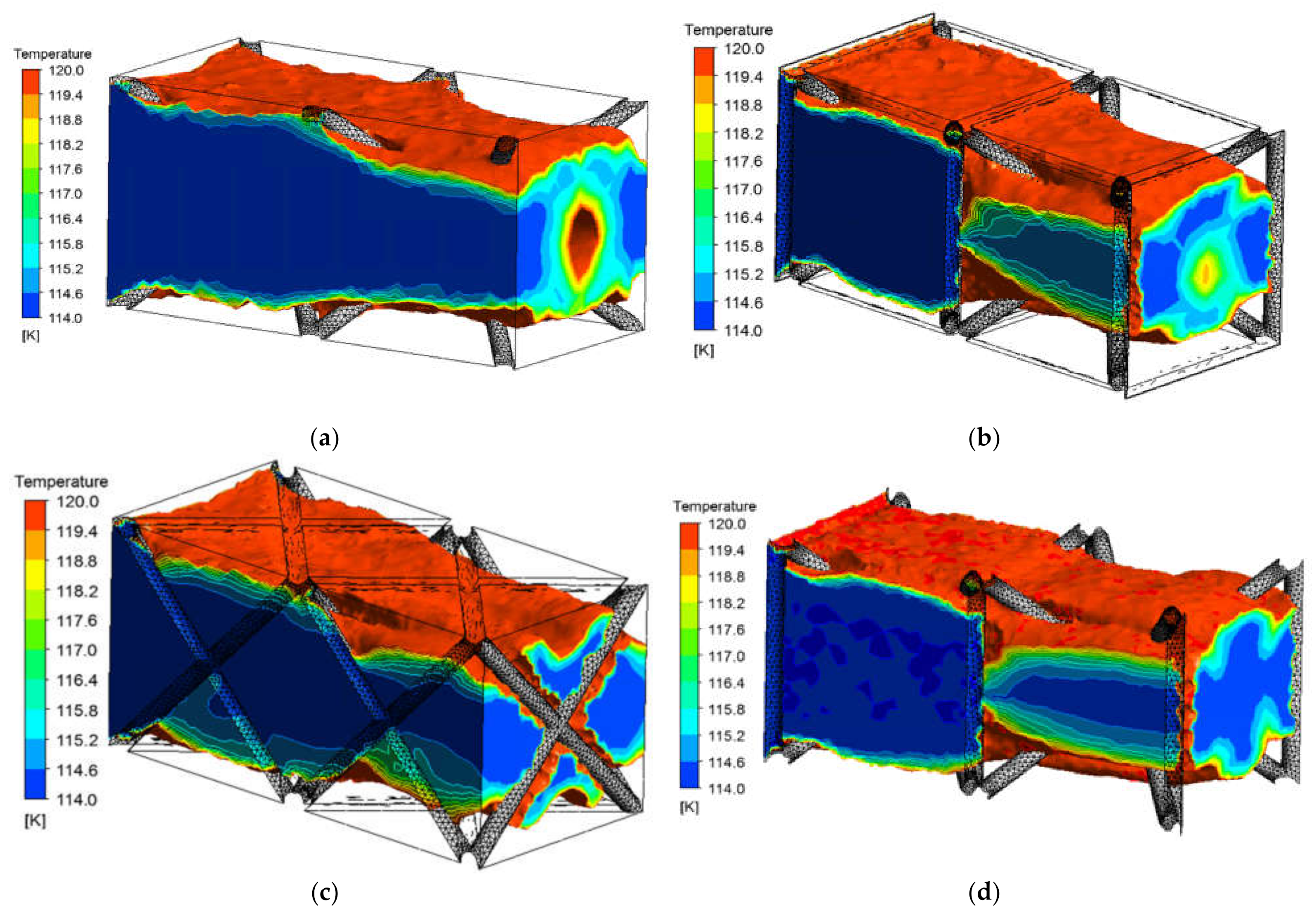
  • The support rod of the lattice structure can be used as a fluid disturbance feature, which is beneficial for driving the heated fluid near the wall to the center of the fluid, thereby improving heat transfer efficiency.
  • The maximum temperature gradient appears at the junction of the support trusses and the heating surface. Considering the strength of the lattice structure and the temperature conductivity, the star type lattice cell is selected as the basic filling structure of the heat exchanger.
  • After the flow is fully developed, the volume of the heated fluid in the star lattice structure accounts for 85.60%, and the heat exchange efficiency is increased by 1.4 times compared with the light pipe structure.

Author Contributions

Conceptualization, Z.W. and X.L.; Investigation, C.W. and H.Y.; Methodology, D.P. and X.L.; Supervision, Z.W. All authors have read and agreed to the published version of the manuscript.

Funding

This research was funded by the Stable Support Project of Military Basic Scientific Research Institutes (2019KGW-YY4007Tm).

Institutional Review Board Statement

Not applicable.

Informed Consent Statement

Not applicable.

Data Availability Statement

Not applicable.

Conflicts of Interest

The authors declare no conflict of interest.

References

  1. Li, H.; Liu, H.; Zou, Z. Experimental study and performance analysis of high-performance micro- channel heat exchanger for hypersonic precooled aero-engine. Appl. Therm. Eng. 2020, 182, 116108. [Google Scholar] [CrossRef]
  2. Xia, G.; Zhuang, D.; Ding, G.; Lu, J.; Han, W.; Qi, H. A distributed parameter model for multi-row separated heat pipe with micro-channel heat exchangers. Appl. Therm. Eng. 2020, 182, 116113. [Google Scholar] [CrossRef]
  3. She, H.; Cui, X.; Weng, J.; Geng, H.; Chang, Z. A combined experimental and numerical approach for printed circuit rectangular microchannel J-T cooler using argon. Appl. Therm. Eng. 2021, 182, 116107. [Google Scholar] [CrossRef]
  4. Ravi, R.; Pachamuthu, S.; Kasinathan, P. Computational and experimental investigation on effective utilization of waste heat from diesel engine exhaust using a fin protracted heat exchanger. Energy 2020, 200, 117489. [Google Scholar] [CrossRef]
  5. Knoke, T.; Kronberg, A.; Glushenkov, M.; Kenig, E.Y. On the design of heat exchanger equipment for novel-type isobaric expansion engines. Appl. Therm. Eng. 2020, 167, 114382. [Google Scholar] [CrossRef]
  6. Kiatpachai, P.; Pikulkajorn, S.; Wongwises, S. Air-side performance of serrated welded spiral fin-and-tube heat exchangers. Int. J. Heat Mass Transf. 2015, 29, 724–732. [Google Scholar] [CrossRef]
  7. Zhicheng, Y.; Lijun, W.; Zhaokuo, Y.; Haowen, L. Shape optimization of welded plate heat exchangers based on grey correlation theory. Appl. Therm. Eng. 2017, 123, 763–769. [Google Scholar] [CrossRef]
  8. Deshpande, V.S.; Ashby, M.F.; Fleck, N.A. Foam topology: Bending versus stretching dominated architectures. Acta Mater. 2001, 49, 1035–1040. [Google Scholar] [CrossRef]
  9. Ali, D.; Ozalp, M.; Blanquer, S.B.; Onel, S. Permeability and fluid flow-induced wall shear stress in bone scaffolds with TPMS and lattice architectures: A CFD analysis. Eur. J. Mech. B Fluid 2020, 79, 376–385. [Google Scholar] [CrossRef]
  10. Bayomy, A.M.; Saghir, M.Z.; Yousefi, T. Electronic cooling using water flow in aluminum metal foam heat sink: Experimental and numerical approach. Int. J. Therm. Sci. 2016, 109, 182–200. [Google Scholar] [CrossRef]
  11. Hossain, S.Z.; Irfan, M.F.; Elkanzi, E.M.; Saif, K.M. Fabrication of a hybrid shell and double pipe heat exchanger by means of design and performance assessment. Chem. Eng. Process. Process Intensif. 2021, 165, 108430. [Google Scholar] [CrossRef]
  12. Abraham, P.; Sharqawy, M.H.; Shawkat, M.E. Thermal and hydraulic characteristics of multiple row spiral finned tube heat exchangers. Int. J. Refrig. 2021, 130, 56–66. [Google Scholar] [CrossRef]
  13. Li, K.; Wen, J.; Yang, H.; Wang, S.; Li, Y. Sensitivity and stress analysis of serrated fin structure in plate-fin heat exchanger on cryogenic condition. Int. J. Therm. Sci. 2019, 145, 106013. [Google Scholar] [CrossRef]
  14. Liu, L.; Ning, D.; Shi, J.; Xu, N.; Guo, W.; Wu, C.L. Failure analysis of tube-to-tubesheet welded joints in a shell-tube heat exchanger. Case Stud. Eng. Fail. Analysis 2016, 7, 32–40. [Google Scholar] [CrossRef] [Green Version]
  15. Kou, H.S.; Lee, J.J.; Chen, C.W. Optimum thermal performance of microchannel heat sink by adjusting channel width and height. Int. Commun. Heat Mass Transf. 2008, 35, 577–582. [Google Scholar] [CrossRef]
  16. Zargoushi, A.; Talebi, F.; Hosseini, S.H. CFD modeling of industrial cold box with plate-fin heat exchanger: Focusing on phase change phenomenon. Int. Commun. Heat Mass Transf. 2019, 147, 118936. [Google Scholar] [CrossRef]
  17. Promvonge, P.; Sripattanapipat, S.; Kwankaomeng, S. Laminar periodic flow and heat transfer in square channel with 45° inline baffles on two opposite walls. Int. J. Therm. Sci. 2010, 49, 963–975. [Google Scholar] [CrossRef]
  18. Goldstein, L.; Sparrow, E.M. Experiments on the transfer characteristics of a corrugated fin and tube heat exchanger configuration. J. Heat Transf. 1976, 98, 26. [Google Scholar] [CrossRef]
  19. Billerot, P.L.; Dufresne, L.; Lemaire, R.; Seers, P. 3D CFD analysis of a diamond lattice-based porous burner. Energy 2020, 207, 118160. [Google Scholar] [CrossRef]
  20. Selimefendigil, F.; Ztop, H.F. Optimization of convective heat transfer performance for fluid flow over a facing step by using an elliptic porous object. Case Stud. Therm. Eng. 2021, 27, 101233. [Google Scholar] [CrossRef]
  21. Jin, N.; Yan, Z.; Wang, Y.; Zhang, H. Effects of heat treatment on microstructure and mechanical properties of selective laser melted Ti-6Al-4V lattice materials. Int. J. Mech. Sci. 2020, 190, 106042. [Google Scholar] [CrossRef]
  22. Kaur, I.; Singh, P. Critical evaluation of additively manufactured metal lattices for viability in advanced heat exchangers. Int. J. Heat Mass Transf. 2021, 168, 120858. [Google Scholar] [CrossRef]
  23. Kaur, I.; Singh, P. Endwall heat transfer characteristics of octahedron family lattice-frame materials. Int. Commun. Heat Mass Transf. 2021, 127, 105522. [Google Scholar] [CrossRef]
  24. Menter, F.R. Two-equation eddy-viscosity turbulence models for engineering applications. AIAA J. 1994, 32, 1598–1605. [Google Scholar] [CrossRef] [Green Version]
  25. Yu, Z.Q.; Feng, Y.L.; Zhou, W.J.; Jin, Y.; Li, M.J.; Li, Z.Y.; Tao, W.Q. Study on flow and heat transfer characteristics of composite porous material and its performance analysis by FSP and EDEP. Appl. Energy 2013, 112, 1367–1375. [Google Scholar] [CrossRef]
  26. Liang, D.; Bai, W.; Chen, W.; Chyu, M.K. Investigating the effect of element shape of the face-centered cubic lattice structure on the flow and endwall heat transfer characteristics in a rectangular channel. Int. J. Heat Mass Transf. 2020, 153, 119579. [Google Scholar] [CrossRef]
  27. Ekade, P.; Krishnan, S. Fluid flow and heat transfer characteristics of octet truss lattice geometry. Int. J. Therm. Sci. 2019, 137, 253–261. [Google Scholar] [CrossRef]
  28. Yan, H.; Yang, X.; Lu, T.; Xie, G. Convective heat transfer in a lightweight multifunctional sandwich panel with X-type metallic lattice core. Appl. Therm. Eng. 2017, 127, 1293–1304. [Google Scholar] [CrossRef]
Figure 1. Partial schematic diagram of the star type lattice structure.
Coatings 11 01089 g001
Figure 2. Unit cell lattice model: (a) grid; (b) vintiles; (c) star; (d) tesseract; (e) X; (f) diamond; (g) octet; (h) honeycomb.
Coatings 11 01089 g002
Figure 3. Relative density and compression deformation of different lattice types.
Coatings 11 01089 g003
Figure 4. Three-dimensional models of different types of lattice structures: (a) grid; (b) X; (c) star; (d) cross; (e) tesseract.
Coatings 11 01089 g004
Figure 5. Inner fluid model of grid lattice structure.
Coatings 11 01089 g005
Figure 6. Distribution of temperature and velocity field of the grid type lattice: (a) temperature (K) and velocity variation (m/s), for z = 0.012 m, t = 0.2 s; (b) temperature (K) and velocity variation (m/s), for z = 0.006 m, t = 0.2 s; (c) temperature variation (K), for z = 0.012 m, t = 0.45 s; (d) velocity variation (m/s), for z = 0.012 m, t = 0.45 s; (e) temperature variation (K), for z = 0.006 m, t = 0.45 s; (f) velocity variation (m/s), for z = 0.006 m, t = 0.45 s; (g) fluid with a temperature greater than 120 K, for t = 0.45 s.
Coatings 11 01089 g006
Figure 7. The isovolumes of the low-temperature fluid of each lattice: (a) X; (b) star; (c) cross; (d) tesseract.
Coatings 11 01089 g007
Figure 8. Relative density and the proportion of the volume of the heated fluid.
Coatings 11 01089 g008
Figure 9. Temperature field distribution of two lattice structures under temperature load: (a) X; (b) star.
Coatings 11 01089 g009
Figure 10. Structure design of the heat exchanger.
Coatings 11 01089 g010
Figure 11. Fully developed flow and high-temperature fluid distribution.
Coatings 11 01089 g011aCoatings 11 01089 g011b
Table 1. Statistics on the proportion of outlet temperature and heating volume.
Type of Heat ExchangerOutlet Temperature/KHigh-Temperature Fluid Volume/m³Total Volume/m³Percentage of High-Temperature Fluid VolumeHeat Exchange Efficiency
Without baffle3224.66 × 10−59.37 × 10−549.73%29.84%
With baffle2826.21 × 10−58.61 × 10−572.13%23.28%
With Star type lattice structure3947.67 × 10−58.96 × 10−585.60%41.64%
Publisher’s Note: MDPI stays neutral with regard to jurisdictional claims in published maps and institutional affiliations.

