Article

Microstructure, Microhardness, Fracture Toughness, and Abrasive Wear of In-Situ Synthesized TiC/Ti-Al Composite Coatings by Cold Spraying Combined with Heat Treatment

1
Xinyu Key Laboratory of Materials Technology and Application for Intelligent Manufacturing, School of Mechanical and Electrical Engineering, Xinyu University, Xinyu 338004, China
2
Jiangxi Province Engineering Research Center of Materials Surface Enhancing & Remanufacturing, School of Mechanical and Materials Engineering, Jiujiang University, Jiujiang 332005, China
3
National Center for International Research of Subsea Engineering Technology and Equipment, Dalian Maritime University, Dalian 116026, China
*
Authors to whom correspondence should be addressed.
Coatings 2021, 11(9), 1034; https://doi.org/10.3390/coatings11091034
Submission received: 8 August 2021 / Revised: 22 August 2021 / Accepted: 24 August 2021 / Published: 27 August 2021
(This article belongs to the Special Issue Friction, Wear Properties and Applications of Coatings)

Abstract

:
TiAl intermetallic compounds, as a new kind of high-performance light-weight structural material, are widely applied in many fields. Titanium carbide (TiC) as the reinforcing phase could improve the mechanical properties, wear resistance, and heat-resistance stability of TiAl intermetallic compounds. Ti(Al, C) mixture powders were deposited by cold spraying at gas temperature of 250 °C, 450 °C, and 550 °C. Then, Ti(Al, C) coatings were annealed at temperatures of 650 °C for different times and following holding at 1100 °C for 3 h. The microstructure, microhardness, fracture toughness, and abrasive wear of Ti-Al composite coatings were investigated. The research results were that the particle size of mixture powders decreased as the ball milling time prolonging. Ti(Al) solid solution appeared in the mixture powders as the milling time increased to 30 h. The average porosity of the coating sprayed at 550 °C was the lowest (0.85%). The as-sprayed coatings exhibited the same phase compositions with the mixture powders. The coating sprayed at gas temperature of 550 °C has the highest microhardness and the lowest weight loss. Ti-Al intermetallic was in-situ synthesized after annealing at 650 °C. The average porosity of the annealed coating (sprayed at 450 °C) was the lowest. The content of Ti-Al intermetallic compounds of the annealed coating sprayed at 450 °C is the highest. The X-ray diffraction (XRD) analysis results are consistent with the EDS analysis of the annealed coatings after annealing at 650 °C. Ti-Al intermetallic compounds were almost completely formed in the three kinds of the coatings after annealing at 650 °C for 20 h and following holding at 1100 °C for 3 h. TiAl and TiAl3 intermetallic phases were in-situ synthesized in the coatings based on the energy dispersive spectroscopy (EDS) and XRD analysis. TiC was also in situ synthesized in the coatings as the annealing temperature increased to 1100 °C. The annealed coating (sprayed at 450 °C) has the highest microhardness, fracture toughness, and wear resistance properties after annealing at 1100 °C for 3 h.

1. Introduction

TiAl intermetallic compounds, as a new kind of high-performance light-weight structural materials are widely applied in fields such as the marine, aerospace, aircraft, and automotive industries, etc. They have advantageous properties such as high melting point, low density, high elastic modulus, good anti-oxidation, high specific strength, and sufficient creep resistance at elevated temperature [1,2,3,4,5,6]. However, the shortcomings of TiAl intermetallic compounds limit their practical applications [7,8,9]. Many researchers have made much effort to overcome the above drawbacks of TiAl intermetallic alloys [10]. The brittleness at room temperature of TiAl intermetallic compounds was improved by additions of alloying elements such as Mo, Cr, Nb, V, and Mn [11,12,13,14,15,16]. Meanwhile, the addition of second ceramic phase particles (e.g., TiB2 [17], Al2O3 [18,19,20], SiC [21], TiC [22,23], Ti2AlC [24], Ti5Si3 [25], and their combination [26,27,28]) to titanium aluminide alloys can further improve the creep resistance, fracture toughness, wear resistance, and heat-resistance stability of TiAl intermetallic compounds. Excellent chemical and mechanical compatibility between ceramic reinforcements and TiAl intermetallic compounds is the key problem to select the reinforcements. Titanium carbide (TiC), due to its unique characteristics such as low density, high microhardness (3000 HV), high melting point (3067 °C), appropriate electroconductivity (21 W/(m K)), low thermal expansivity (7.74 × 10⁻⁶ K−1),and excellent chemical and thermal stability, is often preferentially selected as the reinforcing phase for strengthening TiAl intermetallic compounds [22,23,29]. Therefore, TiC reinforced TiAl composite coatings, which have attracted much attention, were prepared by laser cladding [29,30,31,32]. He et al. [29] have studied the effect of TiC particle size and content on the microstructure and properties of TiC/TiAl composite coating. They found that the coating showed a denser microstructure and better properties with smaller TiC size and a higher concentration. However, the cladding layer with residual stress could induce cracks, and in addition the residual stress of the coating was positively related to the crack rate. Li et al. [30,31] reported that Ti3Al/TiAl+TiC could improve the microhardness and wear resistance of the cladding layer. However, microcracks were also produced by the thermal stress. Thus, it is urgent to select a new and efficient surface technology to reduce the thermal stress and control the composition of the coating.
Cold spraying as a novel surface technology is used to prepared metal (e.g., Ti [33], Cu [34], Al [35], Mg [36], etc), alloy [37], cermet (e.g., WC-Co [38], WC-Ni [39]), ceramic [40], and hydroxyapatite coatings [41]. Therefore, due to its advantages such as low temperature characteristic, high kinetic energy, and compressive stress of the coating [42,43], TiAl or its composite coatings were prepared by cold spraying combined with heat treatment. Novoselova et al. [44] reported that Ti/Al mixture powders were deposited by cold spraying to form Ti/Al coating, and multiple TiAl intermetallic phases (TiAl, TiAl3, Ti3Al, and TiAl2) were generated in the coating after heat treatment at 730 °C. Kong et al. [45] reported that Ti3Al/Al composite coating improved the oxidation resistance of the substrate. Wang et al [46] reported that Al-20 wt% Si powders were deposited on the γ-TiAl substrate by cold spraying process, and then the as-sprayed specimens were annealed at 750 °C for 12 h under the argon gas protection. They also found that TiAl3 intermetallic phase was in-situ synthesized in the Ti (Al, Si)3 diffusion coating, and the diffusion coating was degraded after isothermal and cyclic oxidation tests. However, in previous studies, researchers only focused on the microstructure and oxidation resistance of TiAl coating; there are few reports on the mechanical property of TiAl coatings.
Hence, in order to further analyze the microstructure, microhardness, fracture toughness, and abrasive wear of ceramic phase reinforced Ti-Al composite coating, in situ synthesized TiC reinforced Ti-Al composite coatings have been prepared in this study. The novelty of the study is as follows: (1) in order to avoid the oxidation of spraying materials and the generation of thermal stress in the coating, cold spraying technology was adopted in this study; and (2) based on the characteristics of cold spraying technology, Ti-Al intermetallic phases and TiC were in situ synthesized in the coatings by heat treatment.

2. Materials and Methods

2.1. Powder and Coating Preparation

The surface morphologies of the powders were shown in Figure 1. The commercially available Ti (99.9 wt%, D10 = 2.47 μm, D50 = 11.5 μm, D90 = 41.9 μm; Baoji First Titanium Industry Co., Ltd., Baoji, China), Al (99.99 wt%, D10 = 13.2 μm, D50 = 21.4 μm, D90 = 35.0 μm; Baohang Advanced Materials Co., Ltd., Beijing, China), and C (99.99 wt%, D10 = 29.3 μm, D50 = 41.0 μm, D90 = 56.9 μm; Advanced Corporation for Materials &Equipments Co., Ltd., Changsha, China) were used as raw materials to make a powder mixture. The particle size distribution of Ti, Al, and C powders (as shown in Figure 2) was measured by a laser diffraction meter (GSL-1020, Liaoning Instrument Research Institute Co., Ltd., Liaoning, China). The pure Ti, Al, and C powders were ball-milled for different milling time (6, 12, 18, 24, 30, and 36 h) by a mechanical alloying method to form Ti(Al, C) mixture powders. A planetary ball mill (QM-3SP2, Nanjing Nanda Instrument Plant, Jiangsu, China) was used for ball milling, and the selection of ball milling parameters is a ball-to-powder weight ratio of 10:1 at a rotational speed of 180 rpm. In this study, the atomic ratio of Ti and Al particles in the mixture was 1:1, and the volume fraction of C particle in the mixture was 15 vol%.
A self-made cold spray system (CS-2000, Xi’an Jiaotong University, Xi’an, China) was used to deposite the coatings. A schematic diagram of cold spray system is illustrated in Figure 3. 316 L stainless steel is selected as the substrate. The parameters of cold spraying are listed in Table 1. Prior to spraying, the ball-milled spraying powders were dried in a DZF-6020 vacuum drying oven (Beijing ZhongkeBoda Instrument Technology Co., Ltd., Beijing, China) at 95 °C for 1 h. The rotation rate of scraper powder feeder (Guangzhou Sanxin Metal S & T Co., Ltd., Guangzhou, China) was 100 r/min.

2.2. Annealing Treatment

The as-sprayed specimens were annealed in a 1400 multi-channel mixed pipe furnace (SG-GL1400K, Shanghai Institute of Optics and Fine Mechanics, CAS, Chinese Academy, Shanghai, China) at temperatures of 650 °C for 10, 20, and 30 h. The details heating rate from room temperature to 650 °C are listed in Table 2. And then, in order to further analyze the microstructure evolution of the coatings annealed at higher temperature, the specimens after annealing at 650 °C would be further annealed at 1100 °C for 3 h at a heating rate of 5 °C/min.

2.3. Microhardness, Fracture Toughness, and Abrasive Wear Testing

A digital microhardness tester (HXD-1000 TM/LCD, ShanghaiPrecision Instruments Co., Ltd., Shanghai, China) was applied to measure the microhardness of as-sprayed and annealed coatings. The applied load and dwell time were 2.94 N and 20 s, respectively. The final microhardness value of the coatings was in the mean of 10 random indents. The plain strain fracture toughness (i.e. KIC) of the coatings was evaluated using a Vickers indentation technique at 3 kgf load and 20 s dwell time. An average fracture toughness value was recorded based on five indentations. Fracture toughness (KIC) was calculated by applying the following equation proposed by Niihara [48]:
K I C = 0.0193 ( H v d ) ( E H v ) 2 / 5 ( a ) 1 / 2
where, KIC is the fracture toughness, Hv is the Vickers hardness, d is the half-diagonal of the Vickers indentation, E is the elastic modulus, and a is the indentation crack length.
The elastic modulus of the coatings was determined according to the following formula as established in [49]:
( b a ) = ( b a ) α ( H v E )
where, a and b are the diagonal dimensions of Knoop indenter, a’ and b’ are the long and short diagonal dimensions measured on residual Knoop indentation impression, α is a constant equal to 0.45, and Hv is the Vickers hardness.
The abrasive wear test was carried out according to the literature [47]. The parameters of wear test are listed in Table 3.

2.4. Microstructure Characterization of Powders and Coatings

The mixture powders and polished coating cross sections were analyzed with a scanning electron microscope (SEM; VEGA II-LSU, TESCAN, Brno, Czech Republic). Electron dispersive x-ray spectroscopy (EDS, VEGA II-LSU, TESCAN, Brno, Czech Republic) was used to analyze the elemental composition of the annealed coatings. The phase compositions were determined by X-ray diffraction (XRD; Bruker D8 Advance, Karlsruhe, Germany) using Cu-Kα radiation (λ = 1.5418 Å, 35 kV and 35 mA)a 2θ range from 20° to 90°. The average porosity content (% area) of the coatings, the average content of Ti (% area) in the as-sprayed coatings, and the average content of Ti-Al intermetallic compounds (% area) in the annealed coatings were calculated by Software Image J, performed five SEM micrographs from cross-section morphologies in back-scattered electron (BSE) image mode.

3. Results and Discussion

3.1. XRD Patterns, Morphologies, and Size Distribution of Mixture Powders

Figure 4 shows the XRD patterns of mixture powders. It can be observed that the main compositions of all mixture powders were Ti, Al, and C phases, but the intensity of Ti and Al phase decreased when the ball milling time increased to 18 h. Moreover, Ti(Al) solid solution generated in the mixture powder. This illustrates that after ball milling for a certain time, the diffusion occurred between Ti and Al phases. As the further increase in ball milling time, the intensity of Ti and Al phase continuously decreased. This reveals that the diffusion degree between Ti and Al phases increased during ball milling.
Figure 5 and Figure 6 show the surface and cross-sectional morphologies of mixture powders at different ball milling times, respectively. Since it is difficult to distinguish C phase in the mixture powder, C phase was not marked in the morphologies. It can be seen that the mixture powders ball-milled for 6 h presented nearly spherical morphology (as shown in Figure 5a and Figure 6a), and the various phases were simply mixed together. As the increasing ball milling time, it can be found that the obvious plastic deformation occurred for Al particle, and the microstructure of Ti particle changed from irregular to strip (as shown in Figure 6b indicated by red arrow). Meanwhile, the content of strip Ti particle increased as the ball milling time increased to 18 h (as shown in Figure 6c). The strip structure of the Ti particle would increase the contact area with Al phase, which was beneficial to the mutual diffusion between phases to form Ti(Al) solid solution. The particle size of mixture powders decreased, and the strip Ti particles distributed in the Al phase were brittle broken into short strip particles (as shown in Figure 6d). As the ball milling time was further prolonged, the flocculent structure Ti(Al) solid solution (as indicated by yellow arrow in Figure 6e,f) appeared obviously in mixture powders, and the particle size of mixture powders was also further decreased. The size distribution (D50) of mixture powders after ball milling for different milling time (6, 12, 18, 24, 30, and 36 h) was 68.4 μm, 78.9 μm, 46.4 μm, 35.8 μm, 15.4 μm, and 10.8 μm, respectively.

3.2. Microstructure and XRD Patterns of As-Sprayed Coatings

The quality of cold spray deposits mainly depends on the conditions of powder particles. The particles having an optimum size range could result in high-quality deposits [33]. Ang et al [50] also reported that the properties and performance of the coatings are attributed to powder characteristics. Hence, in order to obtain better coating performance and adapt to the powder characteristics of cold spraying system in this study, the mixture powders ball-milled for 18 h were used to deposit the coating. The cross-sectional morphologies of the coatings were shown in Figure 7. It can be seen that the coatings presented a denser microstructure with no obvious gap or micro-crack. The average porosity of the coatings sprayed at different gas temperatures (250, 450, and 550 °C) was 1.23%, 1.11%, and 0.85%, respectively. It can also be found that Al particles have experienced large plastic deformation upon impact. However, Ti particles underwent only little or no plastic deformation. Meanwhile, Ti and C were dispersed in Al matrix. The average thickness of the coatings sprayed at different gas temperatures (250, 450, and 550 °C) was 615.26 ± 10.16, 911 ± 13.45, and 1167 ± 5.67 μm, respectively. Yin et al [51] reported that increasing gas temperature would increase the particle velocity and facilitate the particle deformation, which would reduce the porosity of the coating and obtain high deposition efficiency. Hence, the porosity of as-sprayed coatings decreased and the thickness increased as the gas temperature increased in this study. In addition, the average content of Ti in the coatings at different gas temperatures (250, 450, and 550 °C) was 28.89 ± 1.06, 41.31 ± 0.97, and 47.74 ± 1.14 vol%, respectively. This illustrates that the content of Ti increased as the gas temperature increased. Meanwhile, the successive flying particles with higher microhardness impact the deposited coating to obtain dense deposits [52]. Hence, the lower porosity of the coating could be obtained owing to the tamping effect by the more content of the Ti particles.
Figure 8 shows the XRD patterns of the coatings. The coatings exhibited the same phase compositions with the mixture powders. Meanwhile, no oxides of Ti and Al were observed in the coatings attributed to the low temperature characteristics of cold spraying. The intensity of phase compositions increased as the gas temperature increased. This also further illustrates that the content of Ti, Al, C, and Ti(Al) phases increased as the gas temperature increased.

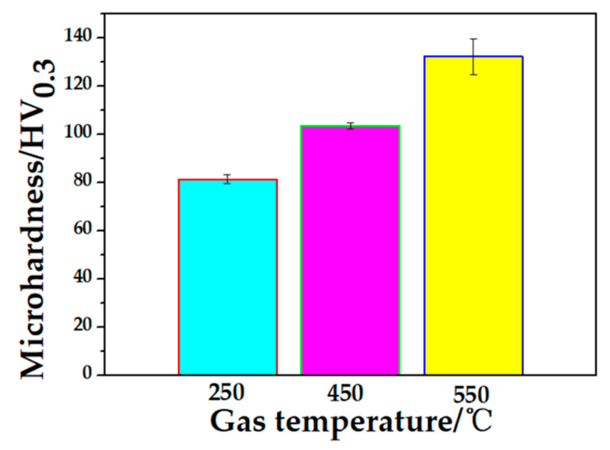
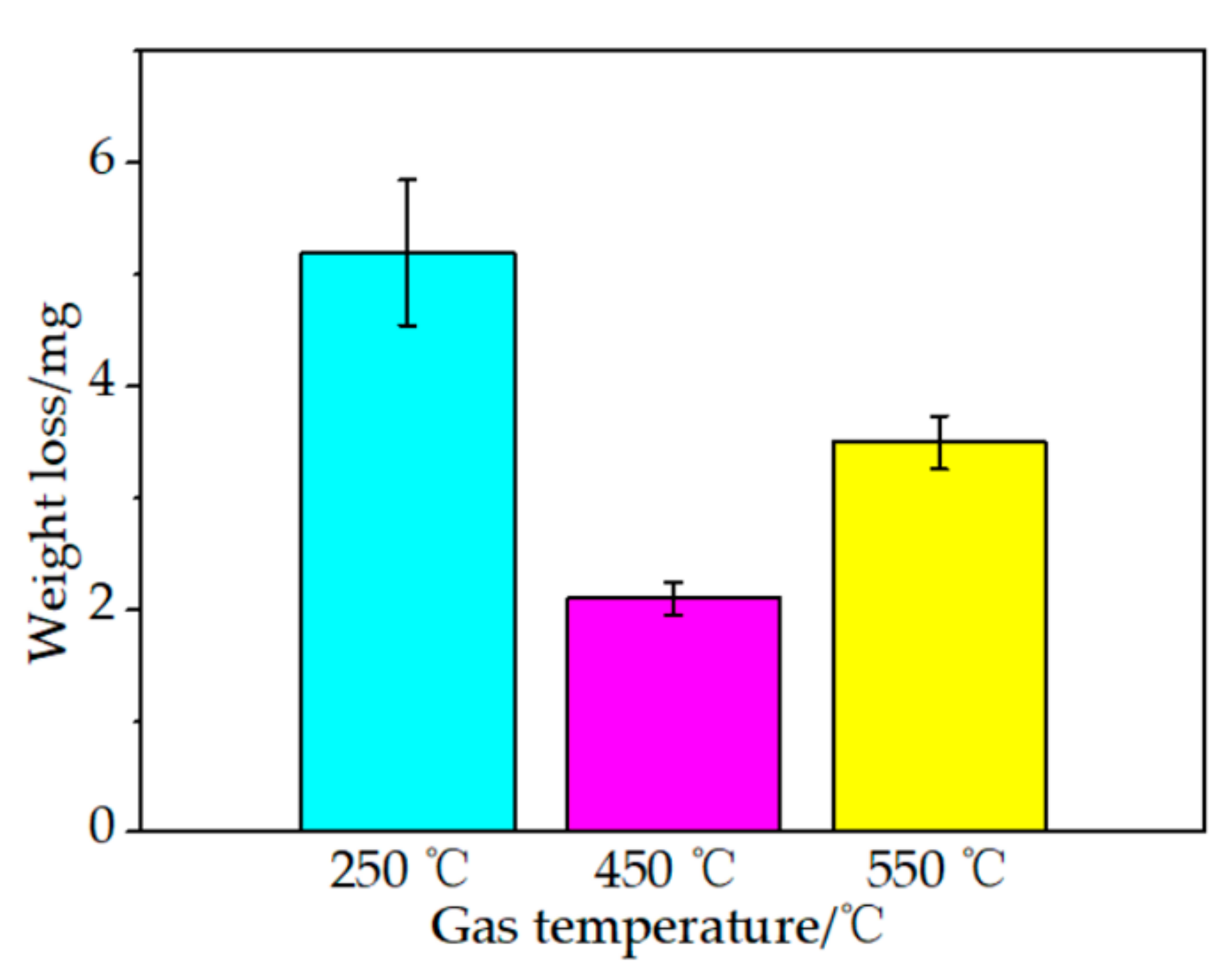
3.3. Microhardness, Fracture Toughness, and Abrasive Wear Behavior of As-Sprayed Coatings

Figure 9 shows the mean microhardness of the coatings at different gas temperature. The highest microhardness of the coating sprayed at gas temperature of 550 °C was 134 ± 7.3 HV0.3. This reveals that the microhardness of the coatings increased as the content of Ti increased. As can be seen from Figure 10, the average fracture toughness value of the coatings was 0.72 ± 0.069, 1.02 ± 0.078, and 1.26 ± 0.031 MPa∙m−1/2, respectively. Hence, increasing the content of Ti could be beneficial to the fracture toughness of the coatings. The weight loss of the coatings at different temperature (250, 450, and 550 °C) was 16.2 ± 0.7, 15.47 ± 0.25, and 12.93 ± 0.23 mg, respectively (as shown in Figure 11). This reveals that, compared with the other coatings, the coating sprayed at 550 °C had the lowest weight loss owing to its highest microhardness and fracture toughness properties.

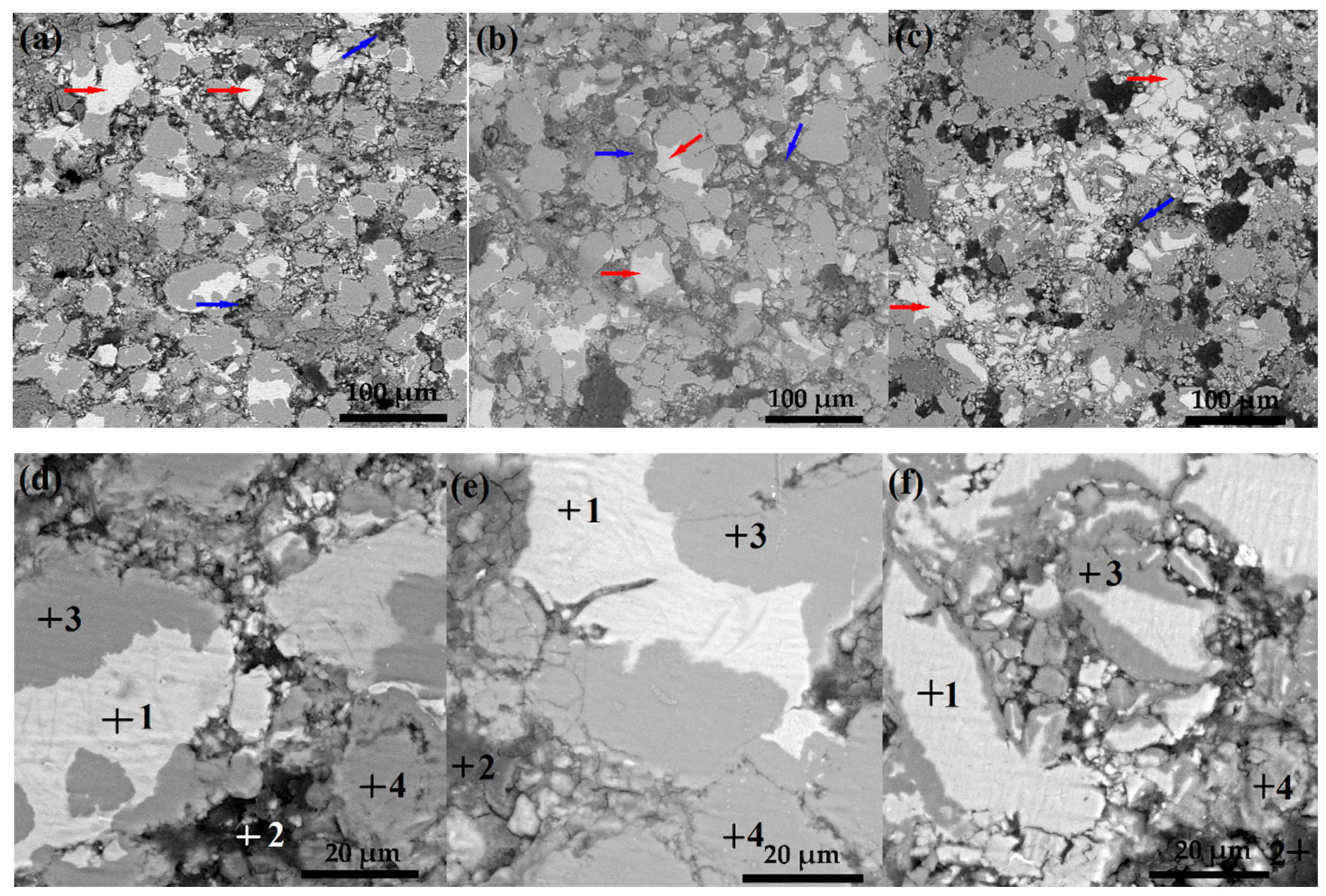
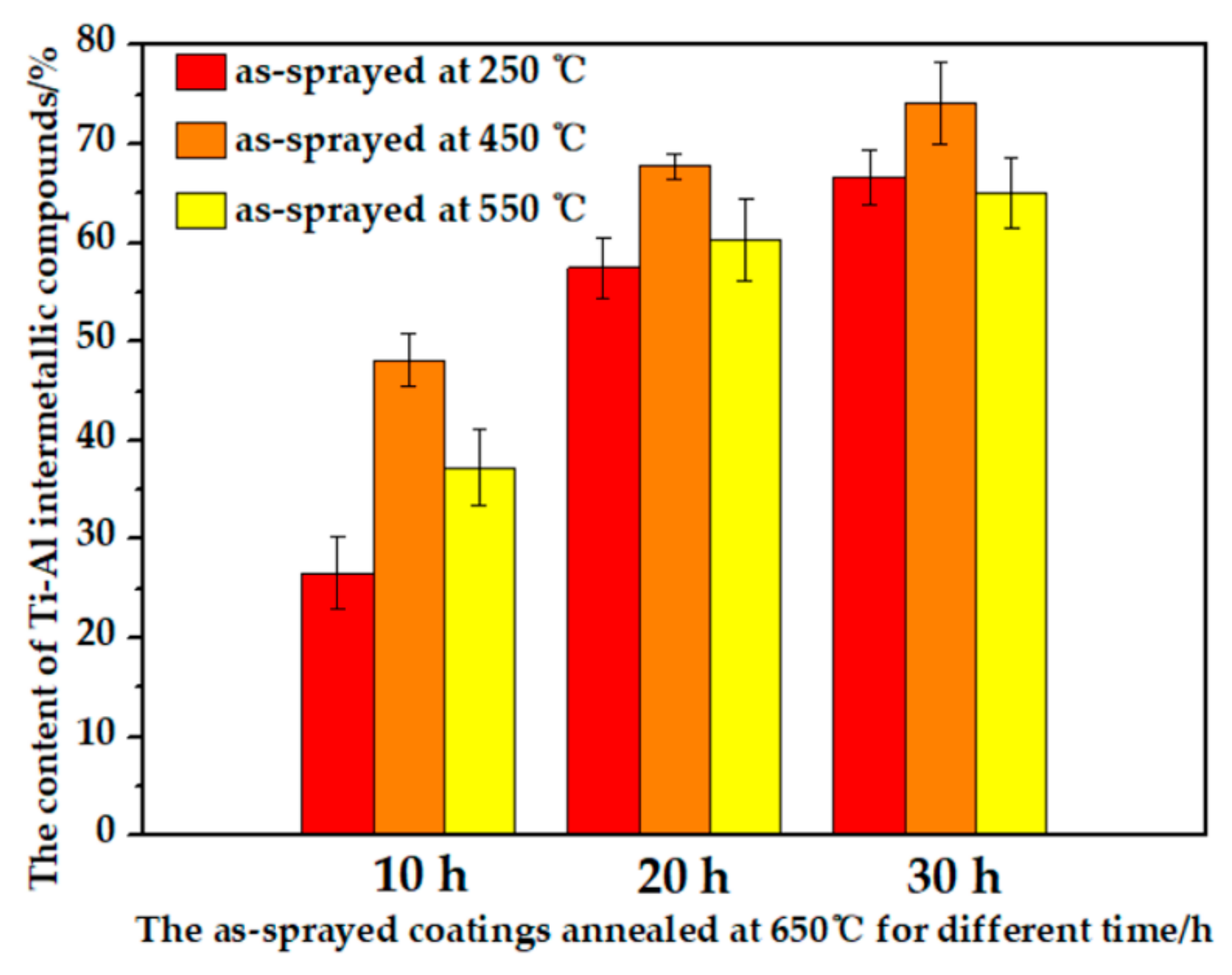
3.4. Microstructure and Composition of Annealed Coatings at 650 °C for Different Time

The cross-sectional morphologies and compositions of as-sprayed coatings annealed at 650 °C for 10, 20, and 30 h were shown in Figure 12, Figure 13 and Figure 14 and Table 4, Table 5 and Table 6, respectively. It can be seen from Figure 12 and Table 4 that the diffusion phenomenon occurred between Ti and Al phases to form TiAl3 intermetallic phase in the coating after annealing at 650 °C for 10 h. Furthermore, there were no cracks or pores between the interface of Ti, Al, and TiAl3 phases. However, a certain Ti (as indicated by the red arrow in Figure 12) and Al (as indicated by the blue arrow in Figure 12) phases remained in the annealed coatings, this illustrates that the diffusion reaction was not completely occurred between Ti and Al at 650 °C for annealing 10 h. After annealing at 650 °C for 20 h, Ti-Al intermetallic compounds were also formed in the coatings (as shown in Figure 13). Meanwhile, TiAl3 intermetallic was also only in situ synthesized in the coatings based on the EDS analysis (as show in Table 5). However, the content of Ti and Al phases decreased in the annealed coatings. This indicates that the reaction diffusion of Ti and Al was more sufficient by prolonging the annealing time. By increasing the annealing time at 650 °C to 30 h, it can be found that Ti and Al in the three kinds of the coatings almost reacted completely to form Ti-Al intermetallic compounds (as shown in Figure 14). Furthermore, Ti3Al, TiAl, and TiAl3 were in situ synthesized in the coatings (as shown in Table 6). This illustrates that, with further increasing the annealing time, the reaction and diffusion between the phases was more sufficient, and more kinds of Ti-Al intermetallic compounds were in-situ synthesized.
By comparing all of the coatings at different annealing time, it also can be found that, due to the content of Ti phase in the coating as-sprayed at 550 °C, thus there was much more Ti phase remained in the coatings after the shorter annealing time (10 h and 20 h, as shown in Figure 12c and Figure 13c). Meanwhile, the interface among the phases of the coatings annealed at 650 °C for 10 h was also well without obvious cracks or pores. However, by increasing the annealing time, the cracks or pores appeared in the coatings by annealing time for 20 h, especially the coatings annealed for 30 h (as shown in Figure 14a–c). The reasons of the cracks or pores formation were reported in [52,53], firstly, the Kirkend all effect induced by the rapid diffusion of Al into the Ti would form the pores in the coatings. Secondly, due to the difference in the density between Ti-Al intermetallic compounds and the original Ti/Al mixture powders, the internal stress increased by the volume change would lead to the formation of cracks. Figure 15 shows the porosity of as-sprayed coatings before and after annealing. Compared with the porosity of as-sprayed coatings, it can be found that the porosity of the coatings annealed at 650 °C for 10 h was similar to that of as-sprayed coatings. However, the porosity of the coatings annealed at 650 °C for 20 h increased, and the average porosity of the annealed coatings (as-sprayed at gas temperature of 250 °C, 450 °C, and 550 °C) was 2.84%, 1.57%, and 3.71%, respectively. Furthermore, the porosity of the annealed coatings remarkably increased (the annealing time for 30 h). The average porosity of the annealed coatings (as-sprayed at 250 °C, 450 °C, and 550 °C) was 8.52%, 7.13%, and 11.4%, respectively. The content of Ti-Al intermetallic compounds in the annealed coatings was shown in Figure 16. The content of Ti-Al intermetallic compounds increased as the annealing time increasing. Meanwhile, it also can be found that, compared with the other annealed coatings as-sprayed at 250 °C and 550 °C, the content of Ti-Al intermetallic compounds of the annealed coating (as-sprayed at 450 °C) is the highest. The decrease of the content of Ti-Al intermetallic compounds in the annealed coating (as-sprayed at 550 °C) is owing to the highest porosity. A small number of particles fell off from the coating during the sample preparation process, which also led to the highest porosity of the coating. Hence, it can reveal that appropriate cold-spraying gas temperature is beneficial to obtain appropriate Ti content in the as-sprayed coating and better microstructure of the annealed coating.
Figure 17 shows the XRD patterns of as-sprayed coatings annealed at 650 °C for different time. This also reveals that TiAl3, Ti, and Al phases appeared in the coatings as the annealing time for 10 h (as shown in Figure 17a). Meanwhile, it can be further found that the intensity of Al phase of the annealed coatings decreased as the cold-spray gas temperature increased. After annealing at 650 °C for 20 h (as shown in Figure 17b), the content of TiAl3 phase was in situ synthesized in the coatings due to the more Al phase reacted with Ti phase. As the annealing time increased to 30 h (as shown in Figure 17c), the XRD patterns of the annealed coatings consisted of TiAl, Ti3Al, and TiAl3 phases. Furthermore, because of the content of Ti phase in the coating sprayed at 550 °C more than the other coatings, the intensity of TiAl and Ti3Al phases was higher than that of the coatings sprayed at as temperature of 250 °C and 450 °C. However, due to the low annealing temperature, TiC phase was not found in the XRD patterns of all of the annealed coatings.

3.5. Microstructure and Composition of Annealed Coatings at 1100 °C for 3 h

Based on the analysis of the research results of as-sprayed coatings annealed at 650 °C, it can be found that the annealed coatings at 650 °C for 20 h has low porosity and moderate content of Ti-Al intermetallic compounds. Therefore, in order to further analyze the microstructure evolution of the coating annealed at higher temperature, the coating after annealing at 650 °C for 20 h was further annealed at 1100 °C for 3 h. The cross-sectional morphologies and compositions of as-sprayed coatings after annealing at 650 °C for 20 h and following holding at 1100 °C for 3 h were shown in Figure 18 and Table 7, respectively. Ti-Al intermetallic compounds were almost completely formed in the three kinds of the coatings by the diffusion between Ti and Al phases. Meanwhile, TiAl (as indicated by the yellow arrow in Figure 18) and TiAl3 (as indicated by the green arrow in Figure 18) intermetallic phases were in-situ synthesized in the coatings based on the EDS analysis (as show in Table 7). Compared with the other annealed coatings (as shown in Figure 18), the coating sprayed at 450 °C gas temperature has denser microstructure after annealing at 1100 °C for 3 h. The average porosity of the annealed coatings (as-sprayed at 250 °C, 450 °C, and 550 °C) was 2.92%, 0.589%, and 1.56%, respectively.
Figure 19 shows the XRD patterns of as-sprayed coatings after annealing at 650 °C for 20 h and following holding at 1100 °C for 3 h. This also reveals that the annealed coatings were composed of TiAl3 and TiAl intermetallic compounds (as shown in Figure 19). Meanwhile, TiC phase (as indicated by the purple arrow in Figure 18) was also in-situ synthesized in the annealed coatings. Compared with the other annealed coatings (as shown in Figure 19a,c), the intensity of TiC phase in the annealed coating (as-sprayed at 450 °C) is the highest (as shown in Figure 19b).

3.6. Microhardness, Fracture Toughness, and Abrasive Wear Behavior of Annealed Coatings at 1100 °C for 3 h

Figure 20 shows the mean microhardness of as-sprayed coatings after annealing at 650 °C for 20 h and following holding at 1100 °C for 3 h. The mean microhardness of the coatings (as-sprayed at 250 °C, 450 °C, and 550 °C) after annealing at 1100 °C for 3 h was 581.8 ± 8.3, 808.0 ± 27.8 HV0.3, and 671.0 ± 16.4, respectively. Compared with the microhardness of as-sprayed coatings (as shown in Figure 9), the microhardness of the coatings after annealing at 1100 °C for 3 h obviously increased. The highest microhardness of the annealed coating (as-sprayed at 450 °C) is about eight times than that of the coating sprayed at 450 °C (103.6 ± 1.32 HV0.3). As can be seen from Figure 21, the average fracture toughness value of the annealed coatings (as-sprayed at 250 °C, 450 °C, and 550 °C) was 11.6 ± 0.85, 14.8 ± 0.37, and 13.7 ± 0.25 MPa∙m−1/2, respectively. This also indicates that the fracture toughness of the annealed coatings was about 12–16 times than that of as-sprayed coatings (as shown in Figure 9). The fracture toughness of the annealed coating (as-sprayed at 450 °C) was slightly higher than that of sintered TiAl intermetallic compound (12.1 MPa∙m−1/2), but lower than that of sintered TiC-TiAl composite material (16.8 MPa∙m−1/2) [54]. The weight loss of the annealed coatings (as-sprayed at 250 °C, 450 °C, and 550 °C) after annealing at 1100 °C for 3 h was 5.2 ± 0.65, 2.1 ± 0.15, and 3.5 ± 0.24 mg, respectively (as shown in Figure 22). This reveals that the wear resistance property of the annealed coating (as-sprayed at gas temperature of 450 °C) after annealing at 1100 °C for 3 h enhanced about 7 times than that of the coating sprayed at 450 °C (15.47 ± 0.25 mg). The main reasons for these phenomena are that, the dense microstructure with lower porosity and in-situ synthesized TiAl, TiAl3, TiC phases are beneficial to improve the microhardness, fracture toughness, and wear resistance of the annealed coatings.
The comprehensive analysis reveals that, the annealed coating (as-sprayed at 450 °C) has the highest microhardness, fracture toughness, and wear resistance properties after annealing at 1100 °C for 3 h. This is mainly attributed to the densest microstructure with the lowest porosity and the highest content of TiC phase in the annealed coating (as-sprayed at 450 °C).

4. Conclusions

Ti(Al, C) mixture powder ball-milled for 18 h was successfully deposited by cold spraying process at different gas temperature to form Ti(Al, C) coatings. Then, the coatings were annealed at 650 °C for different time, and the coating after annealing at 650 °C for 20 h was further annealed at 1100 °C for 3 h. The microstructure, microhardness, fracture toughness, and abrasive wear of in-situ synthesized TiC reinforced Ti-Al composite coatings were investigated. The main conclusions are as follows:
(1) According to the XRD results of the mixture powders, the main compositions of all mixture powders were Ti, Al, and C phases; the intensity of Ti and Al phase decreased, and Ti(Al) solid solution began to generate at the ball milling time for 18 h.
(2) According to the SEM and particle size analysis results of the mixture powders, as the ball milling time increased, the obvious plastic deformation occurred for the Al particle, and the microstructure of the Ti particle changed from irregular to strip. The size distribution (D50) of mixture powders (ball milling time was increased at 6, 12, 18, 24, 30, and 36 h) was 68.4 μm, 78.9 μm, 46.4 μm, 35.8 μm, 15.4 μm, and 10.8 μm, respectively.
(3) The average porosity of the coatings (as-sprayed at 250, 450, and 550 °C) was 1.23%, 1.11%, and 0.85%, respectively. The average thickness of the coatings (as-sprayed at 250, 450, and 550 °C) was 615.26 ± 10.16, 911 ±13.45, and 1167 ± 5.67 μm, respectively. The average content of Ti in the coatings (as-sprayed at 250, 450, and 550 °C) was 28.89 ± 1.06, 41.31 ± 0.97, and 47.74 ± 1.14 vol%, respectively.
(4) The highest microhardness of the coating sprayed at 550 °C was 134 ± 7.3 HV0.3. The average fracture toughness value of as-sprayed coatings was 0.72 ± 0.069, 1.02 ± 0.078, and 1.26 ± 0.031 MPa∙m−1/2, respectively. The weight loss of as-sprayed coatings at different temperature (250, 450, and 550 °C) was 16.2 ± 0.7, 15.47 ± 0.25, and 12.93 ± 0.23 mg, respectively.
(5) TiAl3 intermetallic phase was in situ synthesized in the coatings after annealing at 650 °C for 10 h and 20 h, and there were no cracks or pores between the interface of Ti, Al, and TiAl3 phases. Ti3Al, TiAl, and TiAl3 were in situ synthesized in all of the annealed coatings as the annealing time increased to 30 h.
(6) The average porosity of the annealed coatings (as-sprayed at 250 °C, 450 °C, and 550 °C) after annealing at 650 °C for 10 h was 1.37%, 1.26%, and 1.48%, respectively. The average porosity of the annealed coatings (as-sprayed at 250 °C, 450 °C, and 550 °C) after annealing at 650 °C for 20 h was 2.84%, 1.57%, and 3.71%, respectively. The average porosity of the annealed coatings (as-sprayed at 250 °C, 450 °C, and 550 °C) after annealing at 650 °C for 30 h was 8.52%, 7.13%, and 11.4%, respectively. The content of Ti-Al intermetallic compounds of the annealed coating (as-sprayed at 450 °C) is the highest.
(7) The annealed coatings were composed of TiAl3, Ti, and Al phases as the annealing time for 10 h and 20 h, TiAl, Ti3Al, and TiAl3 phases generated in the coatings as the annealing time for 30 h. Due to the low annealing temperature (650 °C), TiC phase was not found in the annealed coatings.
(8) The average porosity of the coatings (as-sprayed at 250 °C, 450 °C, and 550 °C) after annealing at 650 °C for 20 h and following holding at 1100 °C for 3 h was 2.92%, 0.589%, and 1.56%, respectively.
(9) According to the XRD results of as-sprayed coatings after annealing at 650 °C for 20 h and following holding at 1100 °C for 3 h, the annealed coatings were composed of TiAl3, TiAl, and TiC. The intensity of TiC phase in the annealed coating (as-sprayed at 450 °C) is the highest.
(10) The mean microhardness of the annealed coatings (as-sprayed at 250 °C, 450 °C, and 550 °C) after annealing at 1100 °C for 3 h was 581.8 ± 8.3, 808.0 ± 27.8 HV0.3, and 671.0 ± 16.4, respectively. The highest microhardness of the annealed coating (as-sprayed at 450 °C) is about eight times than that of the coating sprayed at 450 °C (103.6 ± 1.32 HV0.3).
(11) The average fracture toughness value of the annealed coatings (as-sprayed at 250 °C, 450 °C, and 550 °C) after annealing at 1100 °C for 3 h was 11.6 ± 0.85, 14.8 ± 0.37, and 13.7± 0.25 MPa∙m−1/2, respectively. The fracture toughness of the annealed coatings after annealing at 1100 °C for 3 h was about 12–16 times than that of the as-sprayed coatings.
(12) The weight loss of the annealed coatings (as-sprayed at 250 °C, 450 °C, and 550 °C) after annealing at 1100 °C for 3 h was 5.2 ± 0.65, 2.1 ± 0.15, and 3.5 ± 0.24 mg, respectively. The wear resistance property of the annealed coating (as-sprayed at 450 °C) after annealing at 1100 °C for 3 h enhanced about seven times more than that of the coating sprayed at 450 °C (15.47 ± 0.25 mg).
(13) Cold spraying combined with heat treatment is a good and feasible method to prepare TiC/Ti-Al composite coating during controlling the process parameters.

Author Contributions

Conceptualization, X.C.; methodology, X.C. and C.L.; software, Y.H.; validation, X.C. and H.L.; formal analysis, X.C.; investigation, H.L.; resources, X.C.; data curation, X.C. and S.X.; writing—original draft preparation, X.C.; writing—review and editing, X.B.; visualization, X.B.; supervision, S.X.; project administration, X.C.; funding acquisition, X.C. All authors have read and agreed to the published version of the manuscript.

Funding

This research was funded by National Science Foundation of China, grant No. 51861012, the National Natural Science Foundation of JiangXi, grant number 20202BABL204005, the Science and Technology Project of Jiangxi Educational Bureau, grant No. GJJ191049 and GJJ191068, and the Science Technology Project of Jiujiang City, grant No. [2015] No.64.

Institutional Review Board Statement

Not applicable.

Informed Consent Statement

Not applicable.

Data Availability Statement

Not applicable.

Conflicts of Interest

The authors declare no conflict of interest.

References

  1. Tian, Y.S.; Chen, C.Z.; Li, S.T.; Huo, Q.H. Research progress on laser surface modification of titanium alloys. Appl. Surf. Sci. 2007, 242, 177–184. [Google Scholar] [CrossRef]
  2. Clemens, H.; Kestler, H. Processing and applications of intermetallic γ-TiAl-based alloys. Adv. Eng. Mater. 2000, 2, 551–570. [Google Scholar] [CrossRef]
  3. Cheng, J.; Li, F.; Zhu, S.Y.; Yu, Y.; Qiao, Z.H.; Yang, J. Electrochemical corrosion and tribological evalution of TiAl alloy for marine application. Tribol. Int. 2017, 115, 483–549. [Google Scholar] [CrossRef]
  4. Appel, F.; Brossmann, U.; Christoph, U.; Eggert, S.; Janschek, P.; Lorenz, U.; Müllauer, J.; Oehring, M.; Paul, J.D.H. Recent progress in the development of gamma titanium aluminide alloys. Adv. Eng. Mater. 2000, 2, 699–720. [Google Scholar] [CrossRef]
  5. Yamaguchi, M.; Inui, H.; Ito, K. High-temperature structural intermetallics. Acta Mater. 2000, 48, 307–322. [Google Scholar] [CrossRef]
  6. Wu, X. Review of alloy and process development of TiAl alloys. Intermetallics 2006, 14, 1114–1122. [Google Scholar] [CrossRef]
  7. Sauthoff, G. Multiphase intermetallic alloys for structural applications. Intermetallics 2000, 8, 1101–1109. [Google Scholar] [CrossRef]
  8. Wang, T.; Zhang, J. Thermoanalytical and metallographical investigations on the synthesis of TiAl3 from elementary powders. Mater. Chem. Phys. 2006, 99, 20–25. [Google Scholar] [CrossRef]
  9. Lasalmonie, A. Intermetallics: Why is it so difficult to introduce them in gas turbine engines? Intermetallics 2006, 14, 1123–1129. [Google Scholar] [CrossRef]
  10. Ai, T.T.; Deng, Z.F.; Li, W.H.; Dong, H.F.; Zou, X.Y.; Jing, R. Bioinspired design and toughening mechanism of the TC4-(γ-TiAl/α2-Ti3Al) laminated composite fabricated by spark plasma sintering. Mater. Lett. 2020, 273, 1–5. [Google Scholar]
  11. Zhou, Y.; Sun, D.L.; Wang, Q.; Han, X.L. Effect of fabrication parameters on the microstructure and mechanical properties of unidirectional Mo-fiber reinforced TiAl matrix composites. Mater. Sci. Eng. A 2013, 575, 21–29. [Google Scholar] [CrossRef]
  12. Neelam, N.S.; Banumathy, S.; Bhattacharjee, A.; Rao, G.V.S.N.; Alam, M.Z. Comparison of the isothermal and cyclic oxidation behavior of Cr and Mo containing γ-TiAlNb alloys. Corros. Sci. 2019, 163, 108300. [Google Scholar] [CrossRef]
  13. Chenga, T.T.; Willis, M.R.; Jones, I.P. Effects of major alloying additions on the microstructure and mechanical properties of γ-TiAl. Intermetallics 1999, 7, 89–99. [Google Scholar] [CrossRef]
  14. Pilone, D.; Felli, F.; Brotzu, A. High temperature oxidation behaviour of TiAl–Cr–Nb–Mo alloys. Intermetallics 2013, 43, 131–172. [Google Scholar] [CrossRef]
  15. Sun, F.S.; Cao, C.X.; Kim, S.E.; Lee, Y.T.; Yan, M.G. Alloying mechanism of beta stabilizers in a TiAl alloy. Metall. Mater. Trans. A 2001, 32, 1573–1589. [Google Scholar] [CrossRef]
  16. Nansaarng, S.; Srichandr, P. Microstructure and transformation characteristics of a TiAlNb alloy with Cr and Mo addition. Mater. Res. 2012, 15, 63–69. [Google Scholar] [CrossRef] [Green Version]
  17. Yeh, C.; Su, S. In situ formation of TiAl-TiB2 composite by SHS. J. Alloy. Compd. 2006, 407, 150–156. [Google Scholar] [CrossRef]
  18. Li, Z.; Gao, W.; Zhang, D.; Cai, Z. High temperature oxidation behavior of a TiAl-Al2O3 intermetallic matrix composite. Corros. Sci. 2004, 46, 1997–2007. [Google Scholar] [CrossRef]
  19. Amirian, B.; Li, H.Y.; Hogan, J.D. The mechanical response of a α2(Ti3Al)+γ(TiAl)-submicron grained Al2O3 cermet under dynamic compression: Modeling and experiment. Acta Mater. 2019, 181, 291–308. [Google Scholar] [CrossRef]
  20. Li, H.Y.; Motamedi, P.; Hogan, J.D. Characterization and mechanical testing on novel (γ+α2)-TiAl/Ti3Al/Al2O3 cermet. Mater. Sci. Eng. A 2019, 750, 152–163. [Google Scholar] [CrossRef]
  21. Tan, Y.M.; Chen, R.R.; Fang, H.Z.; Liu, Y.L.; Ding, H.S.; Su, Y.Q.; Guo, J.J.; Fu, H.Z. Microstructure evolution and mechanical properties of TiAl binary alloys added with SiC fibers. Intermetallics 2018, 98, 69–78. [Google Scholar] [CrossRef]
  22. Fu, Z.Z.; Mondal, K.C.; Koc, R. Sintering, mechanical, electrical and oxidation properties of ceramic intermetallic TiC-Ti3Al composites obtained from nano-TiC particles. Ceram. Int. 2016, 42, 9995–10005. [Google Scholar] [CrossRef] [Green Version]
  23. Fattahi, M.; Pazhouhanfar, Y.; Delbari, S.A.; Shaddel, S.; Namini, A.S.; Asl, M.S. Strengthening of novel TiC-AlN ceramic with in-situ synthesized Ti3Al intermetallic compound. Ceram. Int. 2020, 46, 14105–14113. [Google Scholar] [CrossRef]
  24. Fang, H.Z.; Chen, R.R.; Liu, Y.L.; Tan, Y.M.; Su, Y.Q.; Ding, H.S.; Guo, J.J. Effects of niobium on phase composition and improving mechanical properties in TiAl alloy reinforced by Ti2AlC. Intermetallics 2019, 115, 106630. [Google Scholar] [CrossRef]
  25. Wu, H.; Leng, J.F.; Teng, X.Y.; Fan, G.H.; Geng, L.; Liu, Z.H. Strain partitioning behavior of in situ Ti5Si3/TiAl composites. J. Alloy. Compd. 2018, 744, 182–186. [Google Scholar] [CrossRef]
  26. Shu, S.; Qiu, F.; Lin, Y.; Wang, Y.; Wang, J.; Jiang, Q. Effect of B4C size on the fabrication and compression properties of in situ TiB2-Ti2AlC/TiAl composites. J. Alloy. Compd. 2013, 551, 88–91. [Google Scholar] [CrossRef]
  27. Shu, S.; Xing, B.; Qiu, F.; Jin, S.; Jiang, Q. Comparative study of the compression properties of TiAl matrix composites reinforced with nano-TiB2 and nano-Ti5Si3 particles. Mater. Sci. Eng. A 2013, 560, 596–600. [Google Scholar] [CrossRef]
  28. Hu, L.F.; Chen, D.M.; Meng, Q.S.; Zhang, H. Microstructure characterization and mechanical properties of (TiC-TiB2)-Ni/TiAl/Ti functionally gradient materials prepared by FAPAS. J. Alloy. Compd. 2015, 636, 298–303. [Google Scholar] [CrossRef]
  29. He, X.; Song, R.G.; Kong, D.J. Effects of TiC on the microstructure and properties of TiC/TiAl composite coating prepared by laser cladding. Opt. Laser Technol. 2019, 112, 339–348. [Google Scholar] [CrossRef]
  30. Li, J.N.; Chen, C.Z.; Squartini, T.; He, Q.S. A study on wear resistance and microcrack of the Ti3Al/TiAl+TiC ceramic layer deposited by laser cladding on Ti-6Al-4V alloy. Appl. Surf. Sci. 2010, 257, 1550–1555. [Google Scholar] [CrossRef]
  31. Li, J.N.; Chen, C.Z.; Zong, L. Microstructure characteristics of Ti3Al/TiC ceramic layer deposited by laser cladding. Int. J. Refract. Met. Hard Mater. 2011, 29, 49–53. [Google Scholar]
  32. Liu, X.B.; Yu, R.L. Microstructure and high-temperature wear and oxidation resistance of laser clad γ/W2C/TiC composite coatings. J. Alloy. Compd. 2007, 439, 279–286. [Google Scholar] [CrossRef]
  33. Li, W.Y.; Cao, C.C.; Yin, S. Solid-state cold spraying of Ti and its alloys: A literature review. Prog. Mater. Sci. 2020, 110, 100633. [Google Scholar] [CrossRef]
  34. Feng, Y.; Li, W.Y.; Guo, C.W.; Gong, M.J.; Yang, K. Mechanical property improvement induced by nanoscaled deformation twins in cold-sprayed Cu coatings. Mater. Sci. Eng. A 2018, 727, 119–122. [Google Scholar] [CrossRef]
  35. Li, W.Y.; Huang, C.J.; Yu, M.; Liao, H.L. Investigation on mechanical property of annealed copper particles and cold sprayed copper coating by a micro-indentation testing. Mater. Des. 2013, 46, 219–226. [Google Scholar] [CrossRef]
  36. Suo, X.K.; Guo, X.P.; Li, W.Y.; Planche, M.P.; Bolot, R.; Liao, H.L.; Coddet, C. Preparation and characterization of magnesium coating deposited by cold spraying. J. Mater. Process. Technol. 2012, 212, 100–105. [Google Scholar] [CrossRef] [Green Version]
  37. Bala, N.; Singh, H.; Prakash, S. Accelerated hot corrosion studies of cold spray Ni-50Cr coating on boiler steels. Mater. Des. 2010, 46, 219–226. [Google Scholar] [CrossRef]
  38. Chen, X.; Wang, H.T.; Ji, G.C.; Bai, X.B.; Dong, Z.X. Deposition behavior of nanostructured WC-23Co particles in cold spraying process. Mater. Manuf. Process. 2016, 31, 1507–1513. [Google Scholar] [CrossRef]
  39. Lioma, D.; Sacks, N.; Botef, I. Cold gas dynamic spraying of WC-Ni cemented carbide coatings. Int. J. Refract. Met. Hard Mater. 2015, 49, 365–373. [Google Scholar] [CrossRef]
  40. Yang, G.J.; Liao, K.X.; Li, C.J.; Fan, S.Q.; Li, C.X.; Li, S. Formation of pore structure and its influence on the mass transport property of vacuum cold sprayed TiO2 coatings using strengthened nanostructured powder. J. Therm. Spray Technol. 2012, 21, 505–513. [Google Scholar] [CrossRef]
  41. Chen, X.; Ji, G.C.; Bai, X.B.; Yao, H.L.; Chen, Q.Y.; Zou, Y.L. Microstructures and properties of cold spray nanostructured HA coatings. J. Therm. Spray Technol. 2018, 27, 1344–1355. [Google Scholar] [CrossRef]
  42. Lupoi, R.; O’Neill, W. Deposition of metallic coatings on polymer surfaces using cold spray. Surf. Coat. Technol. 2010, 205, 2167–2173. [Google Scholar] [CrossRef] [Green Version]
  43. Yin, S.; Suo, X.K.; Guo, Z.W.; Liao, H.L.; Wang, X.F. Deposition features of cold sprayed copper particles on preheated substrate. Surf. Coat. Technol. 2015, 268, 252–256. [Google Scholar] [CrossRef]
  44. Novoselova, T.; Fox, P.; Morgan, R.; O’Neill, W. Experimental study of titanium/aluminium deposits produced by cold gas dynamic spray. Surf. Coat. Technol. 2006, 200, 2775–2783. [Google Scholar] [CrossRef]
  45. Kong, L.Y.; Shen, L.; Lu, B.; Yang, R.; Cui, X.Y.; Li, T.F.; Xiong, T.Y. Preparation of TiAl3-Al composite coating by cold spray and its high temperature oxidation behavior. J. Therm. Spray Technol. 2010, 19, 1206–1210. [Google Scholar] [CrossRef]
  46. Wang, J.Q.; Kong, L.Y.; Li, T.F.; Xiong, T.Y. High temperature oxidation behavior of Ti (Al, Si)3 diffusion coating on γ-TiAl by cold spray. Trans. Nonferrous Met. Soc. China 2016, 26, 1155–1162. [Google Scholar] [CrossRef]
  47. Chen, X.; Li, C.D.; Xu, S.J.; Hu, Y.; Ji, G.C.; Wang, H.T. Microstructure and microhardness of Ni/Al-TiB2 composite coatings prepared by cold spraying combined with postannealing treatment. Coatings 2019, 9, 565. [Google Scholar] [CrossRef] [Green Version]
  48. Niihara, K.; Morena, R.; Hasselman, D.P.H. Evaluation of KIc of brittle solids by the indentationmethod with low crack-to-indent ratios. J. Mater. Sci. Lett. 1982, 1, 13–16. [Google Scholar] [CrossRef]
  49. Marshall, D.B.; Noma, T.; Evans, A.G. A simple method for determining elastic-modulus-to-hardness ratios using Knoop indentation measurements. J. Am. Ceram. Soc. 1982, 65, 175–176. [Google Scholar] [CrossRef]
  50. Ang, A.S.M.; Berndt, C.C.; Cheang, P. Deposition effects of WC particle size on cold sprayed WC-Co coatings. Surf. Coat.Technol. 2011, 205, 3260–3267. [Google Scholar] [CrossRef]
  51. Yin, S.; Suo, X.; Liao, H.; Guo, Z.; Wang, X. Significant influence of carrier gas temperature during the cold spray process. Surf. Eng. 2014, 30, 443–450. [Google Scholar] [CrossRef]
  52. Yang, G.J.; Zhao, S.N.; Li, C.X.; Li, C.J. Effect of phase transformation mechanism on the microstructureof cold-sprayed Ni/Al-Al2O3 composite coatings during post-spray annealing treatment. J. Therm. Spray Technol. 2013, 22, 398–405. [Google Scholar] [CrossRef]
  53. Susan, D.F.; Misiolek, W.Z.; Marder, A.R. Reaction synthesis of Ni-Al-based particle composite coatings. Matell. Mater. Trans. A 2001, 32, 379–390. [Google Scholar] [CrossRef] [Green Version]
  54. Yue, Y.L. Investgation on the Synthesis and Performance of TiC Particulates Reinforced TiAl Intermetallic Matrix Composites. Master’s Thesis, Jinan University, Jinan, China, May 2003. [Google Scholar]
Figure 1. The surface morphologies of the powders (a) Ti, (b) Al, and (c) C.
Coatings 11 01034 g001
Figure 2. The particle size distribution of the powders (a) Ti, (b) Al, and (c) C.
Coatings 11 01034 g002
Figure 3. Schematic diagram of cold spray system: 1, console cabinet; 2, valve; 3, gas heater; 4, accelerating gas pipe; 5, spray gun; 6, powder feeder; 7, thermal couples; 8, display panel; 9, carrier gas; 10, powder feeder gas inlet; 11, accelerating gas inlet.
Coatings 11 01034 g003
Figure 4. The X-ray diffraction (XRD) patterns of mixture powders.
Coatings 11 01034 g004
Figure 5. The surface morphologies of mixture powders (a) 6 h; (b) 12 h; (c) 18 h; (d) 24 h; (e) 30 h; and (f) 36 h.
Coatings 11 01034 g005
Figure 6. The cross-sectional morphologies of mixture powders (a) 6 h; (b) 12 h; (c) 18 h; (d) 24 h; (e) 30 h; and (f) 36 h.
Coatings 11 01034 g006
Figure 7. The cross-sectional morphologies of the as-sprayed coatings (a) 250 °C; (b) 450 °C; and (c) 550 °C.
Coatings 11 01034 g007
Figure 8. XRD patterns of the as-sprayed coatings.
Coatings 11 01034 g008
Figure 9. The microhardness of the as-sprayed coatings.
Coatings 11 01034 g009
Figure 10. The fracture toughness of the as-sprayed coatings.
Coatings 11 01034 g010
Figure 11. Abrasive weight loss of the as-sprayed coatings.
Coatings 11 01034 g011
Figure 12. The cross-sectional morphologies of the as-sprayed coatings after annealing at 650 °C for 10 h; (a,d) 250 °C; (b,e) 450 °C; and (c,f) 550 °C.
Coatings 11 01034 g012
Figure 13. The cross-sectional morphologies of the as-sprayed coatings after annealing at 650 °C for 20 h; (a,d) 250 °C; (b,e) 450 °C; and (c,f) 550 °C.
Coatings 11 01034 g013
Figure 14. The cross-sectional morphologies of the as-sprayed coatings after annealing at 650 °C for 30 h; (a,d) 250 °C; (b,e) 450 °C; and (c,f) 550 °C.
Coatings 11 01034 g014
Figure 15. The porosity of as-sprayed coatings before and after annealing.
Coatings 11 01034 g015
Figure 16. The content of Ti-Al intermetallic compounds in the annealed coatings.
Coatings 11 01034 g016
Figure 17. XRD patterns of as-sprayed coatings annealed at 650 °C for different time: (a) 10 h; (b) 20 h; and (c) 30 h.
Coatings 11 01034 g017
Figure 18. The cross-sectionalmorphologies of as-sprayed coatings after annealing at 650 °C for 20 h and following holding at 1100 °C for 3 h. (a) 250 °C; (b) 450 °C; and (c) 550 °C.
Coatings 11 01034 g018
Figure 19. XRD patterns of as-sprayed coatingsannealedafter annealing at 650 °C for 20 h and following holding at 1100 °C for 3 h. (a) 250 °C; (b) 450 °C; (c) 550 °C.
Coatings 11 01034 g019
Figure 20. The microhardness of as-sprayed coatings annealed after annealing at 650 °C for 20 h and following holding at 1100 °C for 3 h.
Coatings 11 01034 g020
Figure 21. The fracture toughness of as-sprayed coatings annealed after annealing at 650 °C for 20 h and following holding at 1100 °C for 3 h.
Coatings 11 01034 g021
Figure 22. Abrasive weight loss of as-sprayed coatings annealed after annealing at 650 °C for 20 h and following holding at 1100 °C for 3 h.
Coatings 11 01034 g022
Table 1. The parameters of cold spraying [47].
Accelerating GasPowder-Feeding GasAccelerating Gas Pressure (MPa)Powder-Feeding Gas
(MPa)
Standoff Distance
(mm)
Traverse Speed
(mm/s)
Gas Temperature
(°C)
NitrogenNitrogen1.82.02010250, 450, 550
Table 2. The details heating rate from room temperature to 650 °C.
TemperatureHeating Rate (°C/min)
Room temperature—200 °C15
200–300 °C10
300–400 °C8
400–500 °C5
500–650 °C3
Table 3. The parameters of wear test.
ParametersValues
The diameter of specimen (mm)6
SiC abrasive paper600 grit size
Applied load (N)6
Sliding distance (mm)16
Table 4. The compositions of the as-sprayed coatings after annealing at 650 °C for 10 h.
Gas TemperatureSpectrumTi K(at.%)Al K(at.%)Phase
250 °CSpectrum 11000Ti
Spectrum 20100Al
Spectrum 325.1974.81TiAl3
Spectrum 424.0875.92TiAl3
450 °CSpectrum 11000Ti
Spectrum 20100Al
Spectrum 325.7474.26TiAl3
Spectrum 426.1373.87TiAl3
550 °CSpectrum 11000Ti
Spectrum 223.1576.85TiAl3
Spectrum 330.5569.45TiAl3
Spectrum 428.3171.69TiAl3
Table 5. The compositions of the as-sprayed coatings after annealing at 650 °C for 20 h.
Gas TemperatureSpectrumTi K(at.%)Al K(at.%)Phase
250 °CSpectrum 11000Ti
Spectrum 20100Al
Spectrum 320.4579.55TiAl3
Spectrum 426.2773.73TiAl3
450 °CSpectrum 11000Ti
Spectrum 20100Al
Spectrum 328.7671.24TiAl3
Spectrum 427.8372.17TiAl3
550 °CSpectrum 11000Ti
Spectrum 20100Al
Spectrum 327.4672.54TiAl3
Spectrum 437.2062.80TiAl3
Table 6. The compositions of the as-sprayed coatings after annealing at 650 °C for 30 h.
Gas TemperatureSpectrumTi K(at.%)Al K(at.%)Phase
250 °CSpectrum 11000Ti
Spectrum 20100Al
Spectrum 325.1974.81TiAl3
Spectrum 424.0875.92TiAl3
450 °CSpectrum 11000Ti
Spectrum 20100Al
Spectrum 325.7474.26TiAl3
Spectrum 426.1373.87TiAl3
550 °CSpectrum 11000Ti
Spectrum 223.1576.85TiAl3
Spectrum 330.5569.45TiAl3
Spectrum 428.3171.69TiAl3
Table 7. The compositions of the as-sprayed coatings after annealing at 650 °C for 20 h and following holding at 1100 °C for 3 h.
Gas TemperatureSpectrumTi K(at.%)Al K(at.%)Phase
250 °CSpectrum 11000Ti
Spectrum 243.0556.95TiAl
Spectrum 324.5275.48TiAl3
450 °CSpectrum 11000Ti
Spectrum 248.3051.70TiAl
Spectrum 325.5074.50TiAl3
550 °CSpectrum 11000Ti
Spectrum 248.6051.40TiAl
Spectrum 325.3675.64TiAl3
Publisher’s Note: MDPI stays neutral with regard to jurisdictional claims in published maps and institutional affiliations.

