Article

Carbonated Hydroxyapatite-Based Honeycomb Scaffold Coatings on a Titanium Alloy for Bone Implant Application—Physicochemical and Mechanical Properties Analysis

1
Department of Physics, Faculty of Mathematics and Natural Science, Universitas Gadjah Mada, Yogyakarta 55281, Indonesia
2
Department of Dental Biomedical Sciences, Faculty of Dentistry, Universitas Gadjah Mada, Yogyakarta 55281, Indonesia
*
Author to whom correspondence should be addressed.
Coatings 2021, 11(8), 941; https://doi.org/10.3390/coatings11080941
Submission received: 8 July 2021 / Revised: 24 July 2021 / Accepted: 31 July 2021 / Published: 5 August 2021
(This article belongs to the Special Issue Hydroxyapatite Based Coatings for Biomedical Applications)

Abstract

:
In this work, carbonated hydroxyapatite (CHA) based on abalone mussel shells (Haliotis asinina) is synthesized using the co-precipitation method. The synthesized CHA was mixed with honeycomb (HCB) 40 wt.% for the scaffold fabrication process. CHA and scaffold CHA/HCB 40 wt.% were used for coating a Titanium (Ti) alloy using the electrophoretic deposition dip coating (EP2D) method with immersion times of 10, 20, and 30 min. The synthesized B-type CHA with a stirring time of 45 min could have lower transmittance values and smaller crystallite size. Energy dispersive X-ray spectroscopy (EDS) showed that the Ca/P molar ratio was 1.79. The scaffold CHA/HCB 40 wt.% had macropore size, micropore size, and porosity of 102.02 ± 9.88 μm, 1.08 ± 0.086 μm, and 66.36%, respectively, and therefore it can also be applied in the coating process for bone implant applications due to the potential scaffold for bone growth. Thus, it has the potential for coating on Ti alloy applications. In this study, the compressive strength for all immersion time variations was about 54–83 MPa. The average compression strengths of human cancellous bone were about 0.2–80 MPa. The thickness obtained was in accordance with the thickness parameters required for a coating of 50–200 μm.

Graphical Abstract

1. Introduction

For several years, there has been an increased demand for bone replacement or hard tissue damaged from various factors such as osteoarthritis, osteoporosis, dentistry, war-related injuries, and traffic accidents [1]. Currently in Indonesia, bone implants are imported, but with increasing numbers of patients requiring bone replacements there is a need for biomaterials that can be used to regenerate skeletal tissue [1,2,3].
The treatment for bone damage is to use metals such as 316L stainless steel (316L SS) to replace damaged bones. However, this treatment creates problems due to the low level of biocompatibility of the metal, which causes pain and bruising in the surrounding tissue [4]. The 316L SS devices can also result in problems from galvanic corrosion, crevices, and the release of dangerous Cl and Fe ions into tissues. Therefore, because these surfaces are not bioactive, they must be modified using osteoconductive materials such as bioceramics, including hydroxyapatite (HA). These new alternatives are used because they can effectively reconstruct human bone tissue [5,6,7].
HA (Ca10(PO4)6(OH)2) is an alternative material used in biomedical applications [2]. HA has the lattice parameters of a = 9.433Å and c = 6.875Å, and a variable Ca/P mol ratio of 1.67 [8,9]. HA’s advantages are its bioactivity, biocompatibility, and non-corrosiveness. Currently, HA is deposited as a coating on metal coating materials to help suppress the release of harmful metallic ions [10]. Accordingly, HA works as a bioceramic, which has excellent biological characteristics that facilitate bone repair and reconstruction [11].
A recent study was conducted to develop minerals similar to natural bone in terms of crystallinity, chemical composition, and microstructure. Natural bone consists of the mineral carbonate (CO3)2−, which varies based on age, approximately 2%–8% [11] by total weight, in addition to other bone-forming elements. The combination of HA and carbonate minerals from external sources and natural bone is called carbonated hydroxyapatite (CHA). CHA shows better biological properties due to its low crystallinity and increased surface area; consequently, it indicates better bioactivity and is applicable in biomedical applications [12].
CHA (Ca10−x(PO4)6−x(CO3)x(OH)2−x with 0 ≤ x ≤ 2), as a bioceramics candidate for bone implants, consist of three types: B-type (the carbonate ion substitutes the phosphate ion), A-type (the carbonate ion substitutes the hydroxyl ion), and AB-type (the carbonate ion covers the phosphate and hydroxyl ions simultaneously). B-type CHA is the most widely used in biomedical applications [13]. Generally, B-type CHA can reabsorb osteoclasts and is highly soluble in apatite lattices in clinical tests [14]. The combination of carbonate ions and tetrahedral phosphates in B-type CHA causes alterations in the lattice parameters of the crystal structure of CHA [15].
Synthetic CHA can be produced through the reaction of synthetic compounds and the reaction of natural compounds. Natural compounds such as biogenic materials can be obtained from some shells and bones [8]. In this work, the CHA was fabricated using abalone mussel shells (Haliotis asinina) as the natural ingredient and source of calcium from Indonesia because of the higher content of calcium carbonate (CaCO3), which is 90%–95% [16].
CHA can be synthesized using several techniques, including co-precipitation [12,17,18], nano emulsion [19,20], sol-gel [21], mechanical alloying [22], and mechanochemical-hydrothermal methods [23,24]. In this work, the co-precipitation method was selected based on specific considerations: several CHA synthesis approaches do not require any organic solvent, thereby making the process cost-effective; the co-precipitation method is simple as well as cost-effective with a high throughput (87%), which makes it suitable for large-scale production [9].
Biopolymers are increasingly used in biomedical applications due to their chemical similarities with the extracellular matrix of many tissues and their beneficial biological performance [25]. To refine the mechanical and biological behavior of inorganic composite materials, a great deal of interest has focused on organic polymer coatings [1]. As a biopolymer, HCB is interesting for its fully interconnected pores of uniform size and high mechanical strength in the direction of the pores [26]. The HCB architecture is identified by orderly unidirectional macropore or channel that penetrate the materials. Moreover, as a natural polymeric porogen and non-toxic pore-forming agent in a scaffold, HCB structures offer great strength with low weight and less material [27].
Presently, the biomaterials used for dental and orthopedic applications are Ti alloys, stainless steel, magnesium-based alloys, and cobalt-chromium alloys [1,28,29]. Ti and its alloys have become the most popular biomaterials for orthopedic and dental implants [30]. Ti-alloys have proven to be relevant for their excellent corrosion resistance, suitable mechanical properties, attractive biocompatibility, non-toxicity, perfect antibacterial character, average elastic modulus, good strength-to-weight ratio, and superior photocatalysis [1,11,29]. Various methods for the coating process on metal surfaces have also been developed, including dip coating [29], electrophoretic deposition (EPD) [1,3,30,31], sol-gel coating [6,32], and plasma spraying [10]. Among such methods, dip coating and EPD are the easiest; however, the EPD method has a greater chance of cracking due to manual withdrawal of the coating. The presence of cracking in the layer greatly affects the characteristics when implanted in the body [3]. In addition, the coating process using the dip-coating method requires more time [29]. Therefore, it is necessary to combine the two methods in order to have an impact in controlling surface morphology, layer thickness, free cracking, and the formation of a homogeneous layer relatively quickly. The combination of the two methods results in an electrophoretic deposition dip coating (EP2D). This tool is a combination of a series of dip coater devices and EP2D tools that were integrated on the computer. This tool is used for the coating process of CHA and the scaffold CHA/HCB to Ti alloy.
In this work, CHA was fabricated via co-precipitation using calcium carbonate (CaCO3) from abalone mussel shells with stirring time variations. The characteristics of CHA were characterized, including its effect on crystallographic properties, Ca/P molar ratio, its thermal properties, and the functional groups of CHA samples. The best synthesized CHA was mixed with HCB porogen at a concentration of 40 wt.% for the scaffold fabrication treatment. The physicochemical properties of the scaffold CHA/HCB were analyzed using scanning electron microscopy energy dispersive X-ray spectroscopy (SEM-EDS), X-ray diffractometer (XRD), and Fourier transform infrared spectroscopy (FTIR). This study has added the HCB from Indonesia as a biopolymer and porous agent scaffold to CHA. The CHA/HCB confirms the non-toxicity scaffold as shown in previous research [33]. Therefore, the authors tried to coat the Titanium (Ti) alloy with the scaffold CHA/HCB to create CHA/HCB/Ti coatings. CHA and the scaffold CHA/HCB 40 wt.% were used to coat the Ti alloy using the EP2D method developed by the authors with immersion times of 10, 20, and 30 min. The physicochemical properties of CHA/Ti and CHA/HCB/Ti coatings were characterized using SEM and XRD. Evaluation based on compressive strength parameters of CHA/Ti and CHA/HCB/Ti used a universal testing machine (UTM).

2. Materials and Methods

The fabrication was divided into four main steps: synthesis of CHA from abalone mussel shells, fabrication of the scaffold CHA/HCB, CHA/Ti coating, and the CHA/HCB/Ti coating procedure. The schematic procedure for this study can be seen in Figure 1.

2.1. Materials

The abalone mussel shells used as a source of calcium carbonate (CaCO3) were obtained from Bali, Indonesia [9,33]. The precursors of diammonium hydrogen phosphate ([NH4]2HPO4), ammonium bicarbonate (NH4HCO3), and ammonium hydroxide (NH4OH) 25% solution were purchased from Merck (Kenilworth, NJ, USA) [9,33]. Ethanol 96% solution was obtained from Material Physics and Electronics Laboratory, Universitas Gadjah Mada, Yogyakarta, Indonesia. HCB was obtained from Sentra Madu, Yogyakarta, Indonesia. Ti plate (ASTM B265-GR.1) was purchased from NET ARTIDAYA as Engineering and Industrial Support Company, Bekasi, Indonesia.

2.2. Synthesis of CHA

The CaO and CHA were fabricated during prior research, so this study used those samples [9,33]. An amount of 6.048 g of CaO powder was mixed with 60 mL of distilled water for 1 h with a stirring velocity of 350 rpm at room temperature until the solution formed calcium hydroxide (Ca(OH)2. Then, an amount of 8.5536 g (NH4)2HPO4 was mixed with 70 mL of distilled water for 1 h with a stirring velocity of 350 rpm at room temperature. The pH was controlled by adding 15–30 mL of NH4OH 25% into the (NH4)2HPO4 solution while still stirring, until an (NH4)2HPO4 solution was formed in alkaline phase. An amount of 5.1192 g NH4HCO3 was mixed with 50 mL of distilled water for 1 h with a stirring velocity of 350 rpm at room temperature. Then, the NH4HCO3 solution was added dropwise to the (NH4)2HPO4 solution at a rate of 1 mL/min at room temperature while stirring, until the carbonate-phosphate solution was formed. The carbonate-phosphate solution was added dropwise at 1 mL/min to the Ca(OH)2 solution. The solution was stirred at a velocity of 350 rpm for 15 min. In this work, the pH of the mixture was kept above 9 by adding ammonium hydroxide (NH4OH, 25%) 3 M. The compound was stirred at a velocity of 350 rpm for stirring times of 15, 30, and 45 min at a temperature of 60 °C. The solution was subjected to an aging treatment for 24 h and was filtered for 24 h to get the samples’ precipitate. After the filtering process, each sample was purified using 30 mL of distilled water for 20 min at a velocity of 4000 rpm. The sample was dried in an oven at a temperature of 100 °C for 24 h to reduce the moisture content until a dry CHA compound was formed. Finally, CHA was calcined at a temperature of 1050 °C for 2 h.

2.3. Synthesis of Porous CHA-Based HCB Scaffolds

HCB was mixed with the best synthesized CHA to produce the scaffold. Based on previous research [33], the scaffold was fabricated using the HCB wax concentration of 40 wt.% to obtain the pore structure.

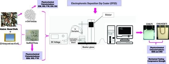
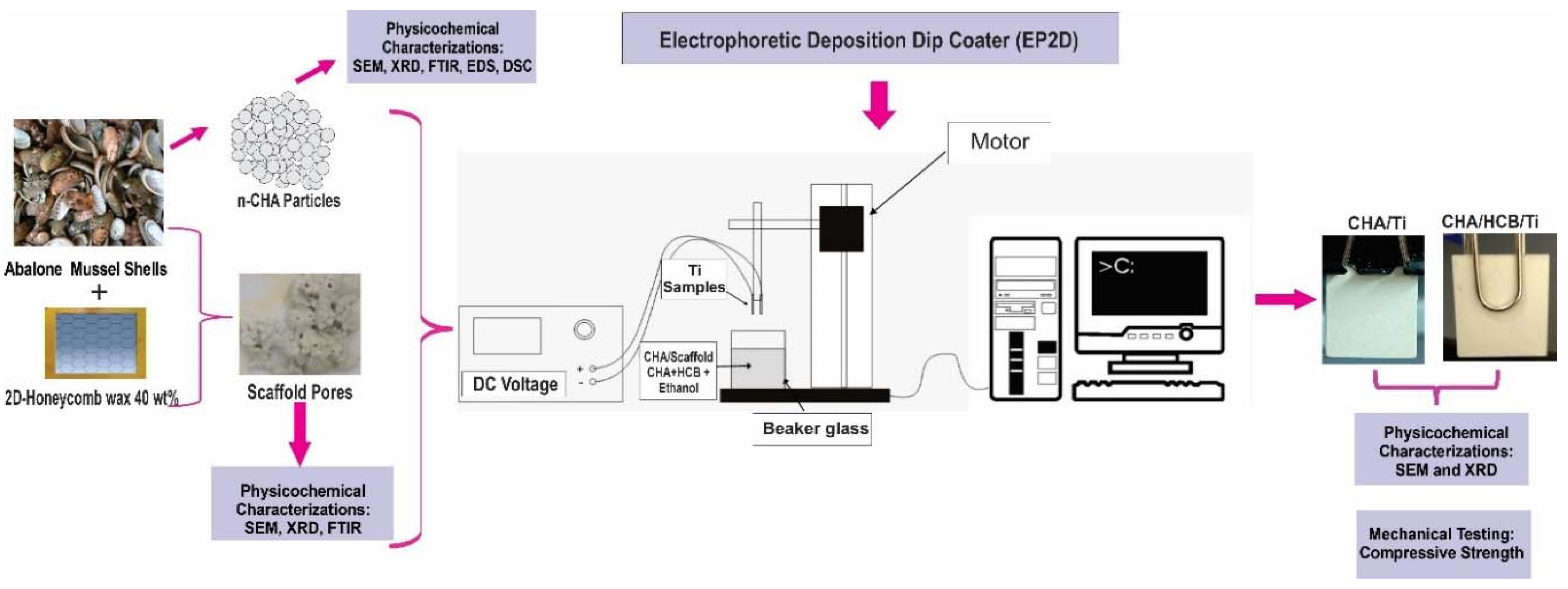
2.4. Coating Procedure for CHA/Ti and CHA/HCB/Ti

2.4.1. Preparation of Substrate for Coating Procedure

The substrate used was Ti alloy cut to 2 cm × 1 cm dimensions and a thickness of 1 mm. The substrate was soaked in acetone solution overnight to omit adhered dirt. All samples were sanded with 1500 grit sandpaper and soaked in acetone again for one night so that they were sterile.

2.4.2. Preparation of CHA and Scaffold CHA/HCB Solutions

An amount of 0.4 g CHA and CHA/HCB was dissolved in 40 mL ethanol 96%. CHA/ethanol and CHA/HCB/ethanol solutions were stirred for 60 min at a temperature of 60 °C. HA has the ability to act as a catalyst, and it has the unusual property of containing an acidic site and a basic site in a single crystal lattice [34]. The stoichiometric HA (Ca10(PO4)6(OH)2) with hexagonal lattice symmetry (P63/m) has structural flexibility [35]. Thus, the HA lattice can undergo considerable distortion by incorporating Ca2+ and PO43− ions of different sizes [35]. Therefore, it is possible to change the acid-base properties of HA by modifying its catalytic activity. By adding OH and/or PO43− ions with CO32− anions to HA, CHA can be produced. Therefore, CHA also has the ability to act as a catalyst that can bind acidic materials (ethanol) and alkaline materials [35]. Thus, CHA is completely soluble in ethanol.

2.4.3. Coatings and Calcination Processes for CHA/Ti and CHA/HCB/Ti

CHA/Ti and CHA/HCB/Ti coatings were applied using EP2D, with two titanium substrates used as the cathode and anode. The CHA/Ti and CHA/HCB/Ti substrates were put into CHA/ethanol and CHA/HCB/ethanol, respectively, and were stirred with a magnetic stirrer (Thermo Fisher Scientific, Waltham, MA, USA) with a DC source voltage of 50 V. The EPD treatment was carried out with immersion time variations of 10, 20, and 30 min. The two substrates were withdrawn from the CHA/ethanol and CHA/HCB/ethanol solution at a velocity of 0.1 mm/s, which was controlled by a stepper motor (PT. Swayasa Prakarsa, Yogyakarta, Indonesia) via computer, as shown in Figure 1. The CHA/Ti and CHA/HCB/Ti were dried at room temperature before being calcinated at 900 °C for 3 h using a furnace (Vulcan, Yucaipa, CA, USA).

2.5. Characterization of CHA Particles, CHA/Ti Coating, and CHA/HCB/Ti Coating

2.5.1. Morphology, Particle Size Distribution, Thickness, and Composition Analysis

The morphology of the CHA and the thickness of CHA/Ti and CHA/HCB/Ti coatings were characterized by SEM-EDS (JEOL JSM-6510LA-1400, Tokyo, Japan). The EDS included in the SEM performed was used to specify the element compositions of the CHA powders. The particle size distribution of the CHA was computed based on the measurements of 100 randomly selected particles using ImageJ software version 2006 (National Institutes of Health (NIH), Bethesda, MD, USA) [36,37].

2.5.2. Crystallographic Analysis

The crystallographic properties of CHA, scaffold CHA/HCB 40 wt.%, and CHA/Ti and CHA/HCB/Ti coatings were analyzed by XRD (PAN analytical Type X’Pert Pro, Tokyo, Japan). The XRD pattern was recorded in the range of 2 θ : 10 80 ° using Cu K α radiation at λ = 0.154   nm [9,33].

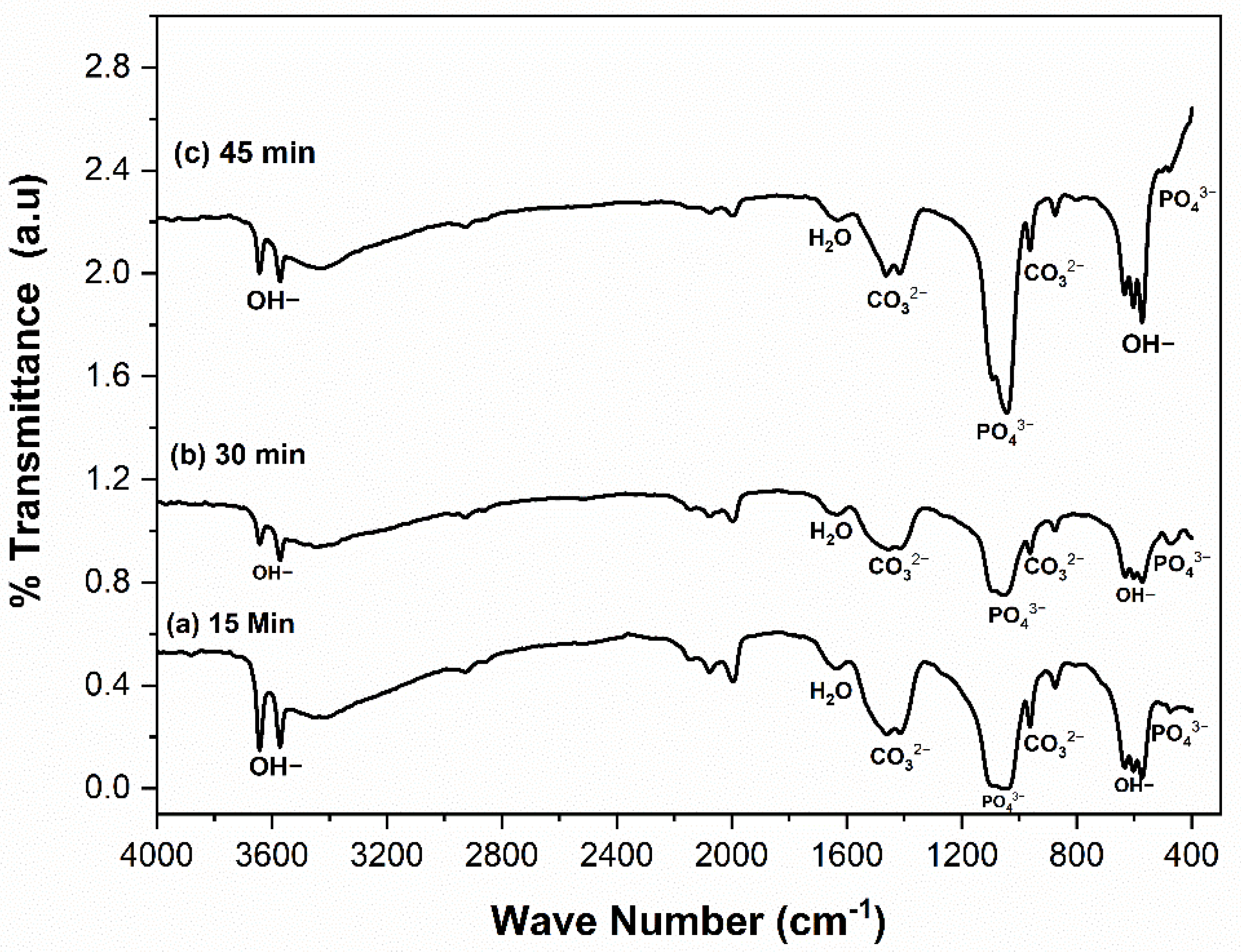
2.5.3. FTIR Analysis

FTIR (Thermo Nicolet iS10, Tokyo, Japan) was used to analyze the functional groups of CHA with stirring time variations and scaffold CHA/HCB 40 wt.%. Separately, the powder and scaffold were milled and mixed with potassium bromide and pressed into compact tablets. The FTIR instrument was operated in the range of 400 4000 cm−1 [33].

2.5.4. Thermal Properties

Differential scanning calorimetry (DSC-60 Plus Shimadzu, Tokyo, Japan) was used to analyze the temperature fusion of the best CHA sample. The CHA measurement was taken using a flow rate of 20 mL/min, starting at room temperature and increasing to 600 °C [33].

2.5.5. Compressive Strength Test and Its Statistical Analysis

Evaluation based on compressive strength parameters used the universal testing machine (TN20MD, Controlab, Paris, France). All compressive strength data were presented as means ± standard deviation (SD) and one-way analysis of variance (ANOVA) was used to analyze the obtained results, followed by Tukey’s test, with p-values < 0.05 considered statistically significant.

3. Results

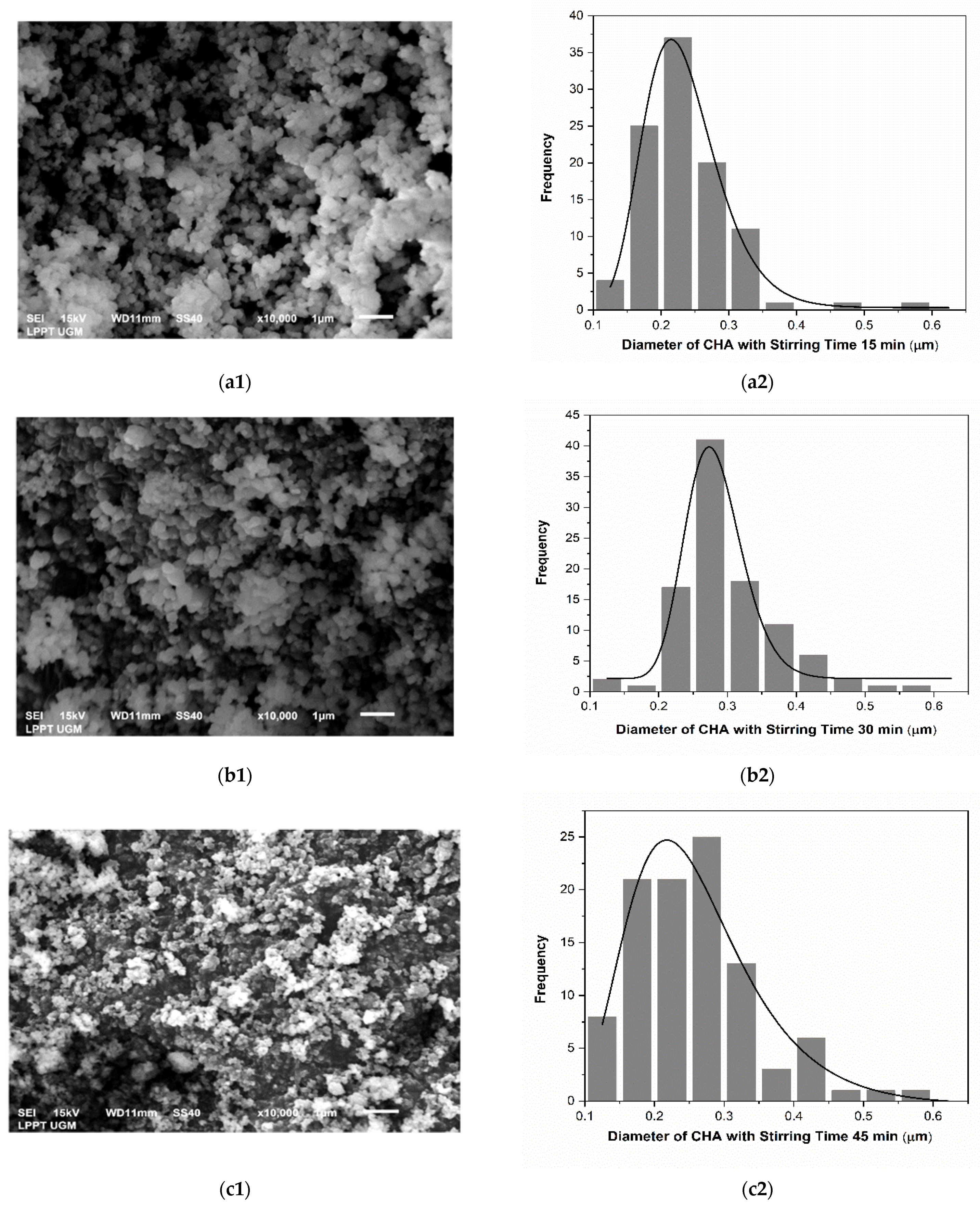
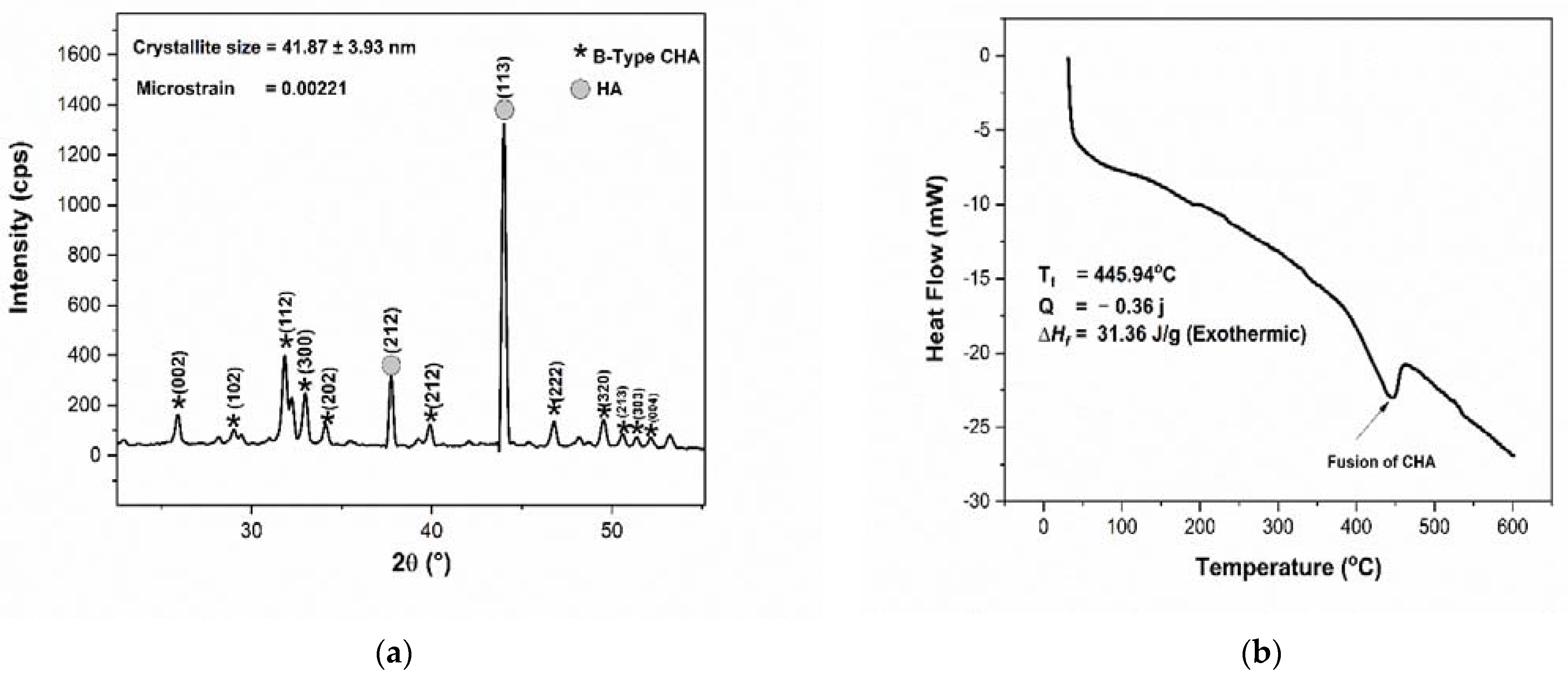
3.1. Physicochemical Analysis of CHA

The morphology and particle size distribution of the CHA with different stirring times are shown in Figure 2. CHA with a stirring time of 30 min had a small agglomerate shape and even structure. CHA with stirring times of 15 and 45 min had a form with large and uneven clumps. These samples were spherical and showed more regular shape at sizes below 1 μm [33]. The morphology results were supported by particle size distribution analysis (Table 1). These data indicate that the variation in stirring time caused the CHA particle sizes to increase.
FTIR analysis is used to identify characteristic CHA function groups, namely PO43−, CO32−, and OH. The FTIR test results (Figure 3) show that the CHA with stirring times of 15, 30, and 45 min exhibited the functional groups of B-type CO32 at 876–875 cm−1 and 1415 1413 cm1. The characteristics of B-type CHA were formed when the carbonate ions switched the phosphate ions in the HA structure [12]. The PO43− absorption was shown at 603 572 and 1050 962 cm−1 for all stirring times. The characterization results showed OH stretching functional groups at 3642 and 3571 cm−1 for all stirring times. The absorption of H2O and mode OH was shown at 1635–1631 and 633–631 cm−1.
Based on data in Table 2, the Ca/P molar ratio tended to increase when the stirring time increased. The EDS analysis for CHA with a stirring time of 45 min revealed a Ca/P molar ratio of 1.79, which approach that of natural bone of 1.71. This result was expected from CHA because the carbonate ions substituted some phosphate ions in their crystal structure [33].
In this study, CHA with a stirring time of 45 min was demonstrated to be the best bioceramic material by its morphology, particle size distribution, and composition characteristics. The crystallographic properties analysis and temperature fusion studies were carried out using XRD and DSC, respectively. Based on the XRD analysis, shown in Figure 4a, the pattern formed was characteristic of B-type CHA and HA. Characteristic HA and CHA peaks are identified (JCPDS No.09-0432) and (JCPDS No. 19-0272), respectively. They formed three characteristic peaks at diffraction angles of 31.83°, 32.92°, and 34.07° with diffraction planes of (112), (300), and (202), respectively. CHA with a stirring time of 45 min had a crystallite size (s) and microstrain ( ε )   of 41.87 ± 3.93 nm and 0.0021, respectively. The results of the DSC analysis can be shown in Figure 4b: it had a fusion temperature of 445.94 °C and an enthalpy of −31.36 j/g. According to DSC analysis, CHA with a stirring time of 45 min underwent an oxidation process. The physicochemical analysis of CHA with a stirring time of 45 min shows that it can be applied in coating processes for bone implant applications.

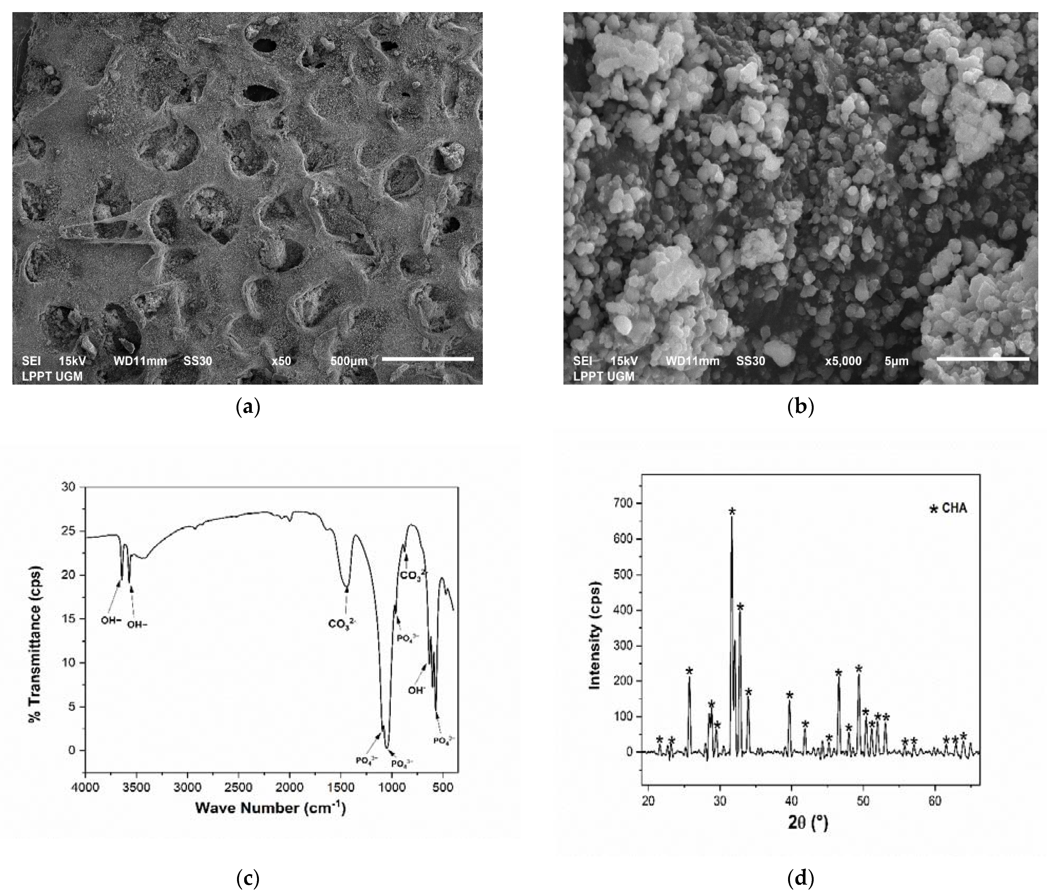
3.2. Physicochemical Analysis of Scaffold CHA/HCB/40 wt.%

The physicochemical properties of scaffold CHA/HCB 40 wt.% were characterized through SEM, XRD, and FTIR. According to the SEM results shown in Table 3 and Figure 5a,b, scaffold CHA/HCB 40 wt.% had macropore and micropore sizes of 102.02 ± 9.88 and 1.08 ± 0.086 μm, respectively. As shown in previous research, scaffold CHA/HCB 40 wt.% also had a porosity of 66.36% [33]. The chemical changes during the fabrication process and crystallographic properties of scaffold CHA/HCB 40 wt.% were investigated by FTIR and XRD, respectively. The FTIR spectra data (Figure 5c) and Table 3 show that scaffold CHA/HCB 40 wt.% showed the functional groups of B-type CO3-HCB v 3   vibration [1]. The XRD pattern of the scaffold (Figure 5d) indicates that the HCB used was completely degraded from the scaffold because it contrasted with the diffraction pattern of the synthesized CHA sample; no other diffraction peaks appeared in each scaffold CHA/HCB 40 wt.% fabrication process [33,38].

3.3. Electrophoretic Deposition Dip Coating (EP2D) of CHA/Ti and CHA/HCB/Ti Coatings

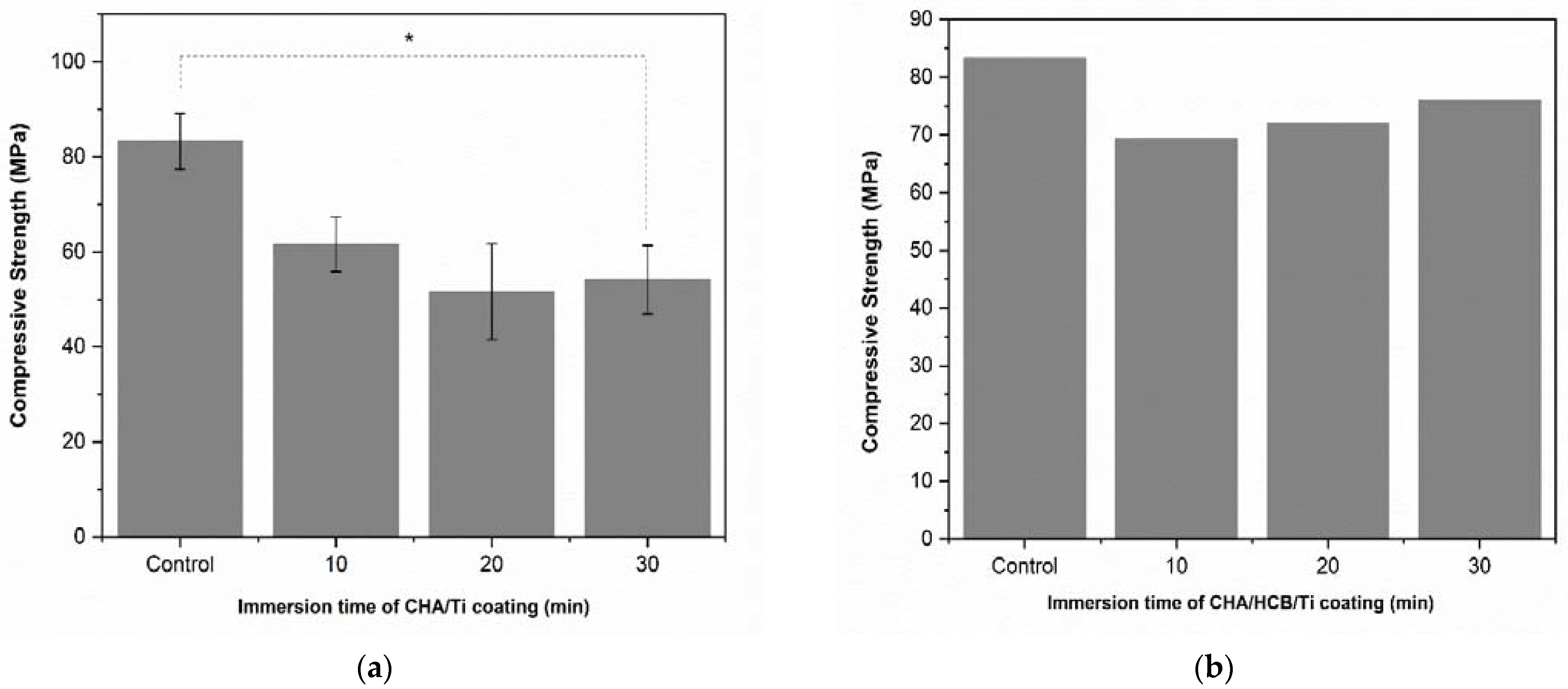
3.3.1. Compressive Strength
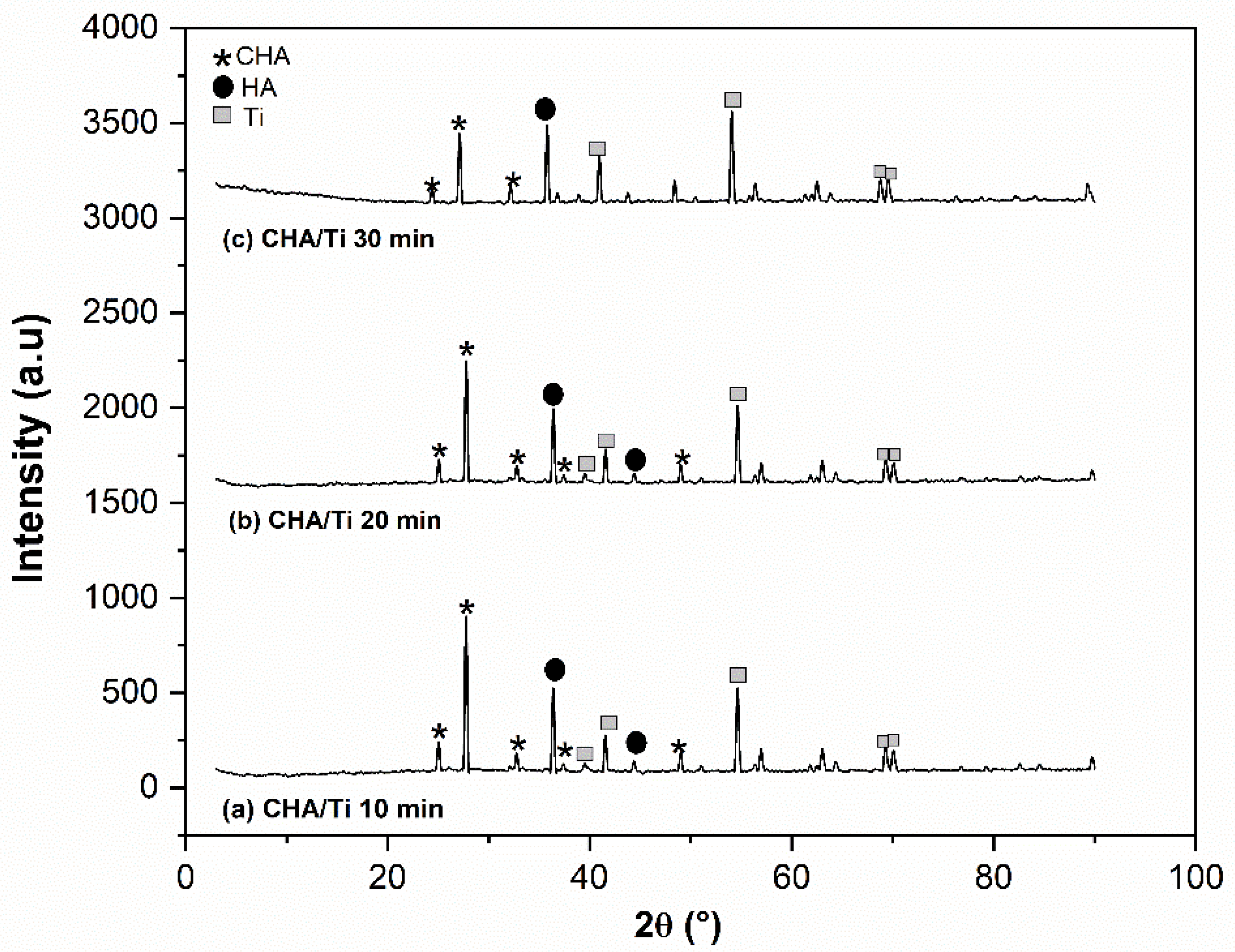
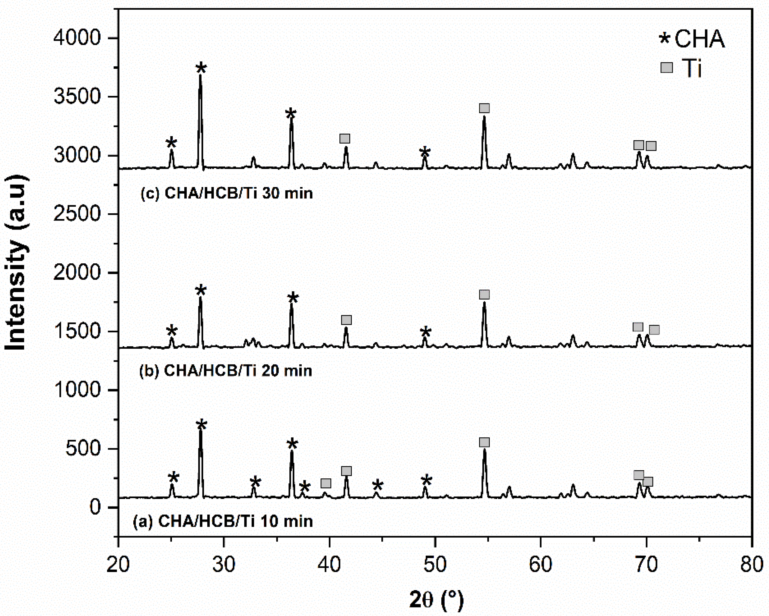
The compressive strength of CHA/Ti and CHA/HCB/Ti with immersion times of 10, 20, and 30 min were investigated, and the results are represented in Table 4 (CHA/Ti coating) and Figure 6a,b. Based on these results, immersion time affected the mechanical properties, including compressive strength [4]. The longer the immersion time, the thicker the bioceramic layer deposited on the substrate surface. The compressive strength tended to increase, as shown in the compressive strength for CHA/HCB/Ti (Figure 6b). However, the CHA/Ti coating for an immersion time of 20 min tended to decrease. This was influenced by the low crystalline characteristic of CHA and the effect of reduced rotation, which caused the stirring velocity to decrease. Therefore, the CHA layer was imperfectly deposited. Based on the one-way ANOVA (Figure 6a) to specify the effect of immersion time on the compressive strength value of CHA/Ti, the p-value was 0.059 (p > 0.05). In this study, no repetition of the CHA/HCB/Ti coating was carried out, so no statistical analysis was done for CHA/HCB/Ti. In this study, the compressive strength value for the control group (Ti alloy) was higher than the experimental group. This is because during the testing process, the Ti plate coated with CHA and scaffold CHA/HCB 40 wt.% was broken after being subjected to pressure from the compressive strength testing tool, so that its compressive strength was reduced.

3.3.2. XRD Analysis

The XRD pattern of the CHA and CHA/HCB layers on Ti alloy for immersion times of 10, 20, and 30 min are shown in Figure 7 and Figure 8. Each XRD pattern showed the CHA, HA, and Ti phases (Figure 7). The XRD pattern of the CHA/Ti and CHA/HCB/Ti coatings was compared with the characteristics of Ti (JCPDS No.89-5009), HA (JCPDS No.09-0432), and CHA (JCPDS No. 19-0272). The XRD pattern only showed the CHA and Ti phases for the scaffold CHA/HCB layer on Ti alloy (Figure 7). Overall, the peak of the CHA phase was more intense for CHA/HCB/Ti than for CHA/Ti, which can be connected to the different thicknesses of the coating [30]. These results will be confirmed through SEM analysis for the thickness of CHA/Ti and CHA/HCB/Ti.
Immersion time treatment of CHA/Ti and CHA/HCB/Ti caused changes in crystallographic properties, including crystallite size, microstrain, and lattice parameter, as shown in Table 5. The immersion time treatment in the coating process of CHA/Ti and CHA/HCB/Ti caused the crystal behavior to increase, so that the width of the diffraction peaks was reduced. Consequently, the crystallite size increased rapidly, while the microstrain decreased as in the CHA/HCB/Ti coatings for all immersion time treatments. As explained in previous research [9,33], the microstrain was a form of crystal imperfection that caused a dislocation. A big microstrain value showed a more significant number of defects in the crystal. However, the CHA/Ti coating with an immersion time of 20 min caused a decrease in crystallite size and an increase in microstrain. This is thought to be related to the intensity of the Ti alloy phase, which was still less intense on the CHA/Ti coating. This was supported by the presence of the HA phase that still appeared on the results of the CHA/Ti coating.
As shown in Table 5, the lattice parameters of the CHA/Ti and CHA/HCB/Ti coatings effected a transformation in value, where the a and c lattice parameters of the samples increased with the length of immersion time. Changes in lattice parameters occurred due to the calcination process during the sample densification process [11,33]. This also resulted in a contraction of the lattice in bioceramic and scaffolded CHA/HCB.

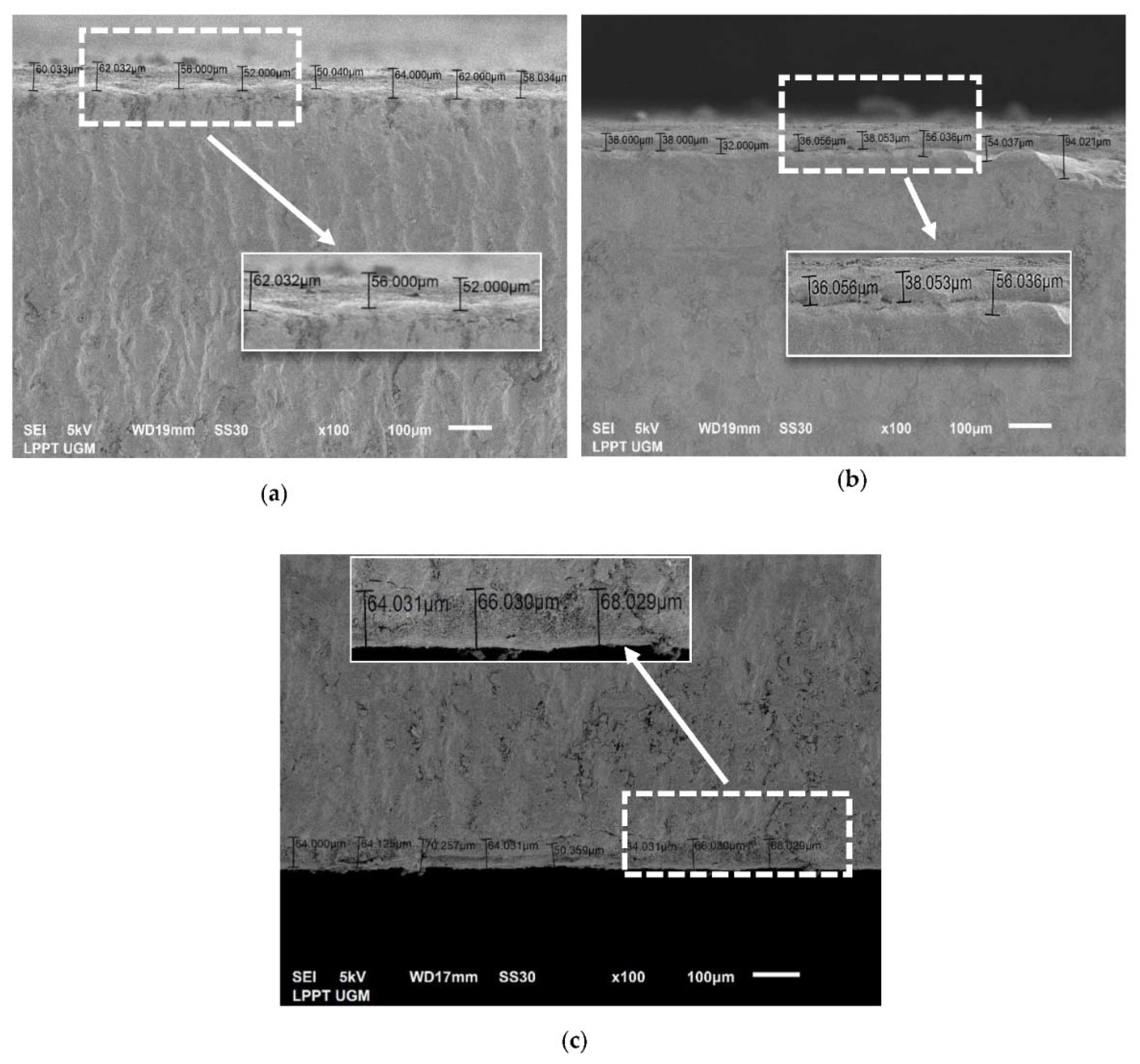
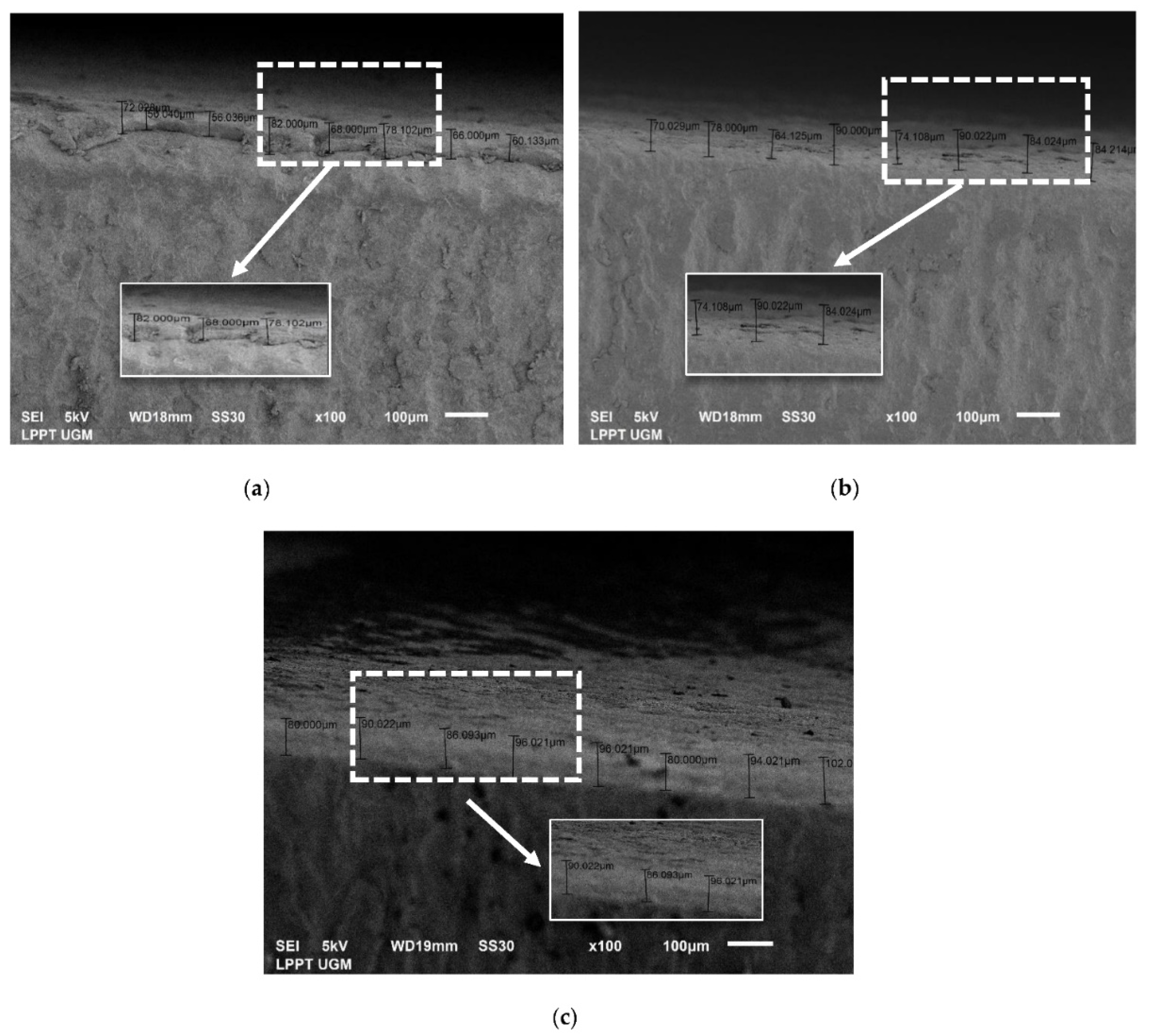
3.3.3. Thickness Analysis by SEM

The thickness of the CHA/Ti and CHA/HCB/Ti coatings for immersion time variations of 10, 20, and 30 min are shown in Figure 9 and Figure 10. In this study, the coating process also used a constant high voltage of 50 V. In the first period of EPD at a constant voltage, thickness increased with time [30,39], but over a more extended period, this effect was not observed, as shown in CHA/Ti for immersion time of 20 min. In this sample, the thickness value decreased (Figure 9 and Table 6).
The immersion time could increase coating thickness, even after a short immersion time of 10 min, as shown in the CHA/HCB/Ti coating (Figure 10 and Table 6). A longer immersion time treatment means the Ti alloy and the CHA and scaffold CHA/HCB suspension are longer. It also affected the increase of CHA and scaffold CHA/HCB deposited on the surface, so the thickness also increases. This will cause more and more samples to stick so that the thickness will increase. Based on the data shown in Table 6, the thickness values for all samples were about 41–88 μm.

4. Discussion

4.1. CHA Synthesized from Abalone Mussel Shells and Scaffold CHA/HCB 40 wt.%

SEM-EDS, XRD, and FTIR were used to investigate the physicochemical properties of CHA with stirring-time variations. Based on SEM analysis (Figure 2 and Table 1), the longer stirring time can cause more agglomeration, thus stirring-time treatment also affects the level of aggregation of the CHA [33,40]. All data pertaining to particle size showed a more normal distribution, while the degree of agglomeration tended to increase (Table 1). Based on the FTIR data (Figure 3), there was a shift in the transmittance value of the carbonate and phosphate groups that tended to be lower and higher values along with the longer stirring times. Therefore, stirring time affected the intensity of the functional group, based on the FTIR [41]. In this result, CHA with the stirring time of 45 min could have a lower transmittance value, thus the carbonate content of this CHA was indicated to be high. The higher carbonate content in CHA also caused the smaller crystallite size of this sample, as shown in Figure 4a. Based on thermal analysis in Figure 4b, CHA with a stirring time of 45 min displayed the OH stretching mode, which is supported by FTIR data [33]. Therefore, it has the potential for coating on Ti alloy applications.
The physicochemical properties of scaffold CHA/HCB 40 wt.% were investigated by using SEM, XRD, and FTIR. According to the SEM results shown in Table 3 and Figure 5a,b, the scaffold CHA/HCB 40 wt.% had the potential scaffold for bone growth and cellular growth orientation. Generally, when the pore size of the scaffold is 1–20 μm, it can be media for cellular growth, while the good macropore size for bone growth is 100–1000 μm [33,42]. Overall, the FTIR spectra provided in Figure 5c show the characteristic spectrum of CHA. The XRD pattern of the scaffold (Figure 5d) indicates the lower crystallinity, which must be lower because it effected dislocations, making it easier for cells to differentiate [9,33]. Based on these analyses, scaffold CHA/HCB 40 wt.% can also be applied in the coating process for bone-implant applications.

4.2. Electrophoretic Deposition Dip Coating (EP2D) of CHA/Ti and CHA/HCB/Ti Coatings

In the EPD process, positively charged CHA and scaffold CHA/HCB 40 wt.% particles moved toward the cathode due to the influence of the electric field, generating an electrostatic force [43]. The layer formed was deposited on the cathode, thus this process was called cathodic electrophoretic deposition. The formation of this layer was caused by the adhesion force that is the source of the bond between the surface of the Ti alloy substrate and the CHA and scaffold CHA/HCB 40 wt.%. This adhesion force caused a bond between the hydrogen atoms of the sample and the substrate. Adhesion was considered the bond strength, which also implied the capacity of an adhesive to stick to the surface and subsequently bond the two surfaces together [3]. In addition, electrostatic forces also encouraged the formation of van der Waals bonds that united the CHA and scaffold CHA/HCB 40 wt.% with Ti alloy [44].
In this study, the compressive strength for all immersion time variations (Figure 6) was about 54–83 MPa, which was within the normal range of human cancellous bone (0.2–80 MPa) [42]. Mechanical properties were highly influenced by the surface morphology and the coating composition [28]. In this study, it was also greatly affected by CHA decomposition, which suppresses densification [11].
The XRD patterns of the CHA and CHA/HCB layers on the Ti alloy are shown in Figure 7 and Figure 8, respectively. As identified from this pattern, the intensity of the CHA peaks increased with increasing contents. HA was still detected in the CHA/Ti layer (Figure 7) because applying the high calcination temperature at 900 °C made this B-type carbonate apatite deposit slightly decompose [3]. Thus, the purity of HA in the formed layer was increasing. Based on Figure 7, the HCB was completely degraded from the scaffold material, so there are no other diffraction peaks in the scaffold CHA/HCB 40 wt.%. Therefore, the absence of different phases besides Ti and scaffold CHA/HCB indicated no reaction between them [11]. In addition, the change in the Ti phase transformation occurred at a temperature of 900 °C, so that it affected the scaffold CHA/HCB layer [3]. Based on SEM analysis (Figure 9 and Figure 10, and Table 6), the thickness obtained was in accordance with the thickness parameters required for coating, namely 50–200 μm. If the coating result is less than 50 μm, it will be absorbed. Conversely, if the upper limit is more than 200 μm, then sufficient maintenance is required [45]. The cross-section for CHA/Ti and CHA/HCB/Ti coatings represented that both layers were directly adjacent to the Ti alloy substrate, with no delamination. The analysis of a porous network in the CHA coatings will be assessed in further research.

5. Conclusions

This work presents a successful fabrication of CHA based on abalone mussel shells with stirring times of 15, 30, and 45 min and the scaffold CHA/HCB 40 wt.%. The morphology of samples showed a high aggregation and more regular shape with sizes below 1 μm. The synthesized CHA formed the same phase as B-type CHA. CHA with the stirring time of 45 min could have lower transmittance values and smaller crystallite sizes. The scaffold CHA/HCB 40 wt.% exhibited the potential scaffold for bone growth and lower crystallinity. Therefore, CHA and the scaffold CHA/HCB 40 wt.% have the potential for coating on the Ti alloy.
This study also presents a successful CHA/Ti and CHA/HCB/Ti coating process using the EP2D method with immersion time variations of 10, 20, and 30 min. The longer the immersion time, the thicker is the bioceramic layer deposited on the substrate surface so that the compressive strength tended to increase, as shown in the compressive strength for CHA/HCB/Ti. However, the compressive strength of the CHA/Ti coating for the immersion time of 20 min tended to decrease. The XRD pattern showed the CHA, HA, and Ti phases for the CHA/Ti coating, but the CHA/HCB/Ti coating only had the CHA and Ti phases. As shown in the SEM analysis, the thickness value of CHA/Ti for an immersion time of 20 min decreased because in the first period of EPD at a constant voltage, thickness increased with time. Still, over a more extended period, this effect was not observed. However, the immersion time could result in an increase in coatings’ thickness, even after a short immersion time of 10 min, as shown in the CHA/HCB/Ti coating. Based on these preliminary results, CHA and scaffold CHA/Ti can potentially be applied to coatings with the Ti alloy.
The development of the EP2D is expected to impact controlling surface morphology, layer thickness, free cracking, and the formation of a homogeneous layer relatively quickly. These results can be seen on layer thickness for CHA/HCB/Ti coatings with immersion times of 10, 20, and 30 min at 71–88 μm. Additionally, the compressive strength for all immersion time variations for CHA/HCB/Ti coatings was about 54–83 MPa, which was within the average of human cancellous bone (0.2–80 MPa). The layer thickness and compressive strength that meet the requirements for bone implant applications are obtained quickly. Therefore, it can attain the goal of developing an electrophoretic deposition dip coating (EP2D) tool integrated into the computer and the use of HCB for CHA/HCB/Ti coating.

Author Contributions

Conceptualization, M.S., C., I.D.A. and Y.Y.; methodology, M.S., N.A.K. and Y.Y.; software, M.S. and Y.Y.; validation, M.S., C., I.D.A. and Y.Y.; formal analysis, M.S., C., I.D.A. and Y.Y.; investigation, M.S., N.A.K. and Y.Y.; resources, M.S. and Y.Y.; data curation, M.S., C., I.D.A. and Y.Y.; writing—original draft preparation, M.S.; writing—review and editing, M.S., C., I.D.A. and Y.Y.; visualization, M.S. and Y.Y.; supervision, C., I.D.A. and Y.Y.; project administration, M.S., N.A.K. and Y.Y.; funding acquisition, Y.Y. All authors have read and agreed to the published version of the manuscript.

Funding

This research was funded by Ministry of Education, Culture, Research, and Technology, 2218/UN1/DITLIT/DIT-LIT/PT/2021 and the Indonesian Endowment Fund for Education (LPDP), KET-1890/LPDP.4/2019.

Institutional Review Board Statement

Not applicable.

Informed Consent Statement

Not applicable.

Data Availability Statement

The data presented in this study are available on request from the corresponding author.

Conflicts of Interest

The authors declare no conflict of interest.

References

  1. Singh, S.; Singh, G.; Bala, N. Electrophoretic deposition of hydroxyapatite-iron oxide-chitosan composite coatings on Ti–13Nb–13Zr alloy for biomedical applications. Thin. Solid. Film. 2020, 697, 137801. [Google Scholar] [CrossRef]
  2. Syafaat, F.Y.; Yusuf, Y. Effect of Ca:P concentration and calcination temperature on hydroxyapatite (HAp) powders from quail eggshell (Coturnix Coturnix). Int. J. Nanoelectron. Mater. 2018, 11, 51–58. [Google Scholar]
  3. Kriswanto, M.; Khairurrijal, M.; Wajong, D.L.J.; Kadarismanto, T.M.; Yusuf, Y. Stainless steel 316 L metal coating with capiz shell hydroxyapatite using electrophoretic deposition method as bone implant candidate. Key Eng. Mater. 2020, 840, 336–344. [Google Scholar] [CrossRef]
  4. Mulya, N.; Fadli, A.; Amri, A. Pengaruh penambahan hidroksiapatit dan waktu pencelupan terhadap pelapisan logam stainless steel 316L dengan metode dip coating. JOM Fteknik 2016, 3, 1–7. [Google Scholar]
  5. Gopi, D.; Ramya, S.; Rajeswari, D.; Kavitha, L. Corrosion protection performance of porous strontium hydroxyapatite coating on polypyrrole coated 316L stainless steel. Coll. Surf. B Biointerfaces 2013, 107, 130–136. [Google Scholar] [CrossRef]
  6. Ahmadi, R.; Afshar, A. In vitro study: Bond strength, electrochemical and biocompatibility evaluations of TiO2/Al2O3 reinforced hydroxyapatite sol–gel coatings on 316L SS. Surf. Coat. Technol. 2021, 405, 126594. [Google Scholar] [CrossRef]
  7. Ana, I.D.; Satria, G.A.P.; Dewi, A.H. Bioceramics for Clinical Application in Regenerative Dentistry; Springer: Singapore, 2018; pp. 309–316. [Google Scholar]
  8. Sari, M.; Yusuf, Y. Synthesis and characterization of hydroxyapatite based on green mussel shells (Perna viridis) with calcination temperature variation using the precipitation method. Int. J. Nanoelectron. Mater. 2018, 11, 357–370. [Google Scholar]
  9. Sari, M.; Hening, P.; Chotimah; Ana, I.D.; Yusuf, Y. Bioceramic hydroxyapatite-based scaffold with a porous strructure using honeycomb as a natural polymeric porogen for bone tissue engineering. Biomater. Res. 2021, 25, 1–13. [Google Scholar] [CrossRef]
  10. Singh, A.; Singh, G.; Chawla, V.J. Characterization and mechanical behaviour of reinforced hydroxyapatite coatings deposited by vacuum plasma spray on SS-316L alloy. J. Mech. Behav. Biomed. Mater. 2018, 79, 273–282. [Google Scholar] [CrossRef]
  11. Permatasari, H.A.; Supii, A.I.; Suparta, G.B.; Yusuf, Y. Characteristics of abalone mussel shells (Halioitis asinina) with calcination temperature variations as a basic material for synthesis of carbonated hydroxyapatite. Key Eng. Mater. 2019, 818, 31–36. [Google Scholar] [CrossRef]
  12. Youness, R.A.; Taha, M.A.; Ibrahim, M.A. Effect of sintering temperatures on the in vitro bioactivity, molecular structure and mechanical properties of titanium/carbonated hydroxyapatite nanobiocomposites. J. Mol. Struct. 2017, 1150, 188–195. [Google Scholar] [CrossRef]
  13. Safarzadeh, M.; Ramesh, S.; Tan, C.Y.; Chandran, H.; Noor, A.F.M.; Krishnasamy, S.; Alengaram, U.J.; Ramesh, S. Effect of multi-ions doping on the properties of carbonated hydroxyapatite bioceramic. Ceram. Int. 2019, 45, 3473–3477. [Google Scholar] [CrossRef]
  14. Permatasari, H.A.; Yusuf, Y. Characteristics of carbonated hydroxyapatite based on abalone mussel shells (Halioitis asinina) synthesized by precipitation method with aging time variations. IOP Conf. Ser. Mater. Sci. Eng. 2019, 546, 042031. [Google Scholar] [CrossRef]
  15. Almukarrama; Yusuf, Y. Development carbonated hydroxyapatite powders from oyster shells (Crassostrea gigas) by sintering time controlling. IOP Conf. Ser. Mater. Sci. Eng. 2019, 546, 042001. [Google Scholar] [CrossRef]
  16. Laonapakul, T. Synthesis of hydroxyapatite from biogenic wastes. KKU Eng. J. 2015, 42, 269–4275. [Google Scholar]
  17. Wati, R.; Yusuf, Y. Effect of sintering temperature on carbonated hydroxyapatite derived from common cockle shells (Cerastodermaedule): Composition and crystal characteristics. Key Eng. Mater. 2019, 818, 37–43. [Google Scholar] [CrossRef]
  18. Anggraini, R.M.; Supii, A.I.; Suparta, G.B.; Yusuf, Y. The effect of pH on the characteristics of carbonate hydroxyapatite based on pearl shell (Pinctada maxima). Key Eng. Mater. 2019, 818, 44–49. [Google Scholar] [CrossRef]
  19. Zhou, W.Y.; Wang, M.; Cheung, W.L.; Guo, B.C.; Jia, D.M. Synthesis of carbonated hydroxyapatite nanospheres through nanoemulsion. J. Mater. Sci. Mater. Med. 2008, 19, 103–110. [Google Scholar] [CrossRef]
  20. Ezekiel, I.; Kasim, S.R.; Ismail, Y.M.B.; Noor, A.F.M. Nanoemulsion synthesis of carbonated hydroxyapatite nanopowders: Effect of variant CO32−/PO43− molar ratios on phase, morphology, and bioactivity. Ceram. Int. 2018, 44, 13082–13089. [Google Scholar] [CrossRef]
  21. Rajabi-Zamani, A.H.; Behnamghader, A.; Kazemzadeh, A. Synthesis of nanocrystalline carbonated hydroxyapatite powder via nonalkoxide sol–gel method. Mater. Sci. Eng. C 2008, 28, 1326–1329. [Google Scholar] [CrossRef]
  22. Lala, S.; Brahmachari, S.; Das, P.K.; Das, D.; Kar, T.; Pradhan, S.K. Biocompatible nanocrystalline natural bonelike carbonated hydroxyapatite synthesized by mechanical alloying in a record minimum time. Mater. Sci. Eng. C 2014, 42, 647–656. [Google Scholar] [CrossRef]
  23. Kumar, T.S.; Manjubala, I.; Gunasekaran, J. Synthesis of carbonated calcium phosphate ceramics using microwave irradiation. Biomaterials 2000, 21, 1623–1629. [Google Scholar] [CrossRef]
  24. Kong, W.; Zhao, K.; Gao, C.; Zhu, P. Synthesis and characterization of carbonated hydroxyapatite with layered structure. Mater. Lett. 2019, 255, 126552. [Google Scholar] [CrossRef]
  25. Avcu, E.; Bastan, F.E.; Abdullah, H.Z.; Rehman, M.A.U.; Avcu, Y.Y.; Boccaccini, A.R. Electrophoretic deposition of chitosan-based composite coatings for biomedical applications: A review. Prog. Mater. Sci. 2019, 103, 69–108. [Google Scholar] [CrossRef]
  26. Ishikawa, K.; Munar, M.L.; Tsuru, K.; Miyamoto, Y. Fabrication of carbonate apatite honeycomb and its tissue response. J. Biomed. Mater. Res. Part A 2019, 107, 1014–1020. [Google Scholar] [CrossRef]
  27. Thomas, T.; Tiwari, G. Crushing behaviour of honeycomb structure: A review. Int. J. Crashworthiness 2019, 24, 1–25. [Google Scholar] [CrossRef]
  28. Ananth, K.P.; Suganya, S.; Mangalara, D.; Ferreira, J.M.F.; Balamurugan, A. Electrophoretic bilayer deposition of zirconia and reinforced bioglass system on Ti6Al4V for implant applications: An in vitro investigation. Mater. Sci. Eng. C 2013, 33, 4160–4166. [Google Scholar] [CrossRef] [PubMed]
  29. Aminatun; Apsari, R.; Yusuf, Y.; Suhariningsih. Synthesis and characterization of hydroxyapatite layer on cobalt alloys through dip coating method as a prosthetic bone implant candidate. J. Optoelectron. Biomed. Mater. 2015, 7, 11–18. [Google Scholar]
  30. Bartmanski, M.; Cieslik, B.; Glodowska, J.; Kalka, P.; Pawlowski, L.; Pieper, M.; Zielinski, A. Electrophoretic deposition (EPD) of nanohydroxyapatite-nanosilver coatings on Ti13Zr13Nb alloy. Ceram. Int. 2017, 43, 11820–11829. [Google Scholar] [CrossRef]
  31. Li, M.; Xiong, P.; Mo, M.; Cheng, Y.; Zheng, Y. Electrophoretic-deposited novel ternary silk fibroin/graphene oxide/hydroxyapatite nanocomposite coatings on titanium substrate for orthopedic applications. Front. Mater. Sci. 2016, 10, 270–280. [Google Scholar] [CrossRef]
  32. Balaji, J.; Oh, T.W.; Sethurahman, M.G. Effects of pH on inhibitor-doped hybrid protective sol–gel coatings on the copper electrode surface. J. Taiwan Inst. Chem. Eng. 2021, 119, 2–11. [Google Scholar] [CrossRef]
  33. Sari, M.; Hening, P.; Chotimah; Ana, I.D.; Yusuf, Y. Porous structure of bioceramics carbonated hydroxyapatite-based honeycomb scaffold for bone tissue engineering. Mater. Today Commun. 2021, 26, 102135. [Google Scholar] [CrossRef]
  34. Tsuchida, T.; Kubo, J.; Yoshioka, T.; Sakuma, S.; Takeguchi, T.; Ueda, W. Reaction of ethanol over hydroxyapatite affected by Ca/P ratio of catalyst. J. Catal. 2008, 259, 183–189. [Google Scholar] [CrossRef]
  35. Lovon-Quintana, J.J.; Rodriguez-Guerrero, J.K.; Valenca, P.G. Carbonated Hydroxyapatite as a catalyst for ethanol conversion to hydrocarbon fuels. Appl. Catal. A Genera 2017, 542, 136–145. [Google Scholar] [CrossRef]
  36. Igathinathane, C.; Pordesimo, L.O.; Columbus, E.P.; Batchelor, W.D.; Methuku, S.R. Shape identification and particles size distribution from basic shape parameters using ImageJ. Comp. Electron. Agric. 2008, 63, 168–182. [Google Scholar] [CrossRef]
  37. Writing ImageJ Plugins-A Tutorial. Available online: https://imagej.nih.gov/ij/index.html (accessed on 20 July 2021).
  38. Heimann, R.B. Materials Science of Crystalline Bioceramics: A Review of Basic Properties and Applications. CMU J. 2002, 1, 23–46. [Google Scholar]
  39. Abdeltawab, A.A.; Shoeib, M.A.; Mohamed, S.G. Electrophoretic deposition of hydroxyapatite coatings on titanium from dimethylformamide suspensions. Surf. Coat. Technol. 2011, 206, 43–50. [Google Scholar] [CrossRef]
  40. Mawuntu, V.J.; Yusuf, Y. Porous structure engineering of bioceramic hydroxyapatite-based scaffolds using PVA, PVP, and PEO as polymeric porogens. J. Asian Ceram. Soc. 2019, 7, 1–9. [Google Scholar] [CrossRef] [Green Version]
  41. Sari, M.; Yusuf, Y. Synthesis and characterization of hydroxyapatite based on green mussel shells (perna viridis) with the variation of stirring time using the precipitation method. IOP Conf. Ser. Mater. Sci. Eng. 2018, 432, 012046. [Google Scholar] [CrossRef] [Green Version]
  42. Cheng, M.; Wahafu, T.; Jiang, G.; Liu, W.; Qiao, Y.; Peng, X.; Cheng, T.; Zhang, X.; He, G.; Liu, X. A novel open-porous magnesium scaffold with controllable microstructures and properties for bone regeneration. Nat. Publ. Gr. 2016, 6, 1–14. [Google Scholar] [CrossRef] [Green Version]
  43. Besra, L.; Liu, M. A review on fundamentals and applications of electrophoretic deposition (EPD). Prog. Mater. Sci. 2007, 52, 1–61. [Google Scholar] [CrossRef]
  44. Harun, W.S.W.; Asri, R.I.M.; Alias, J.; Zulkifli, F.H.; Kadirgama, K.; Ghani, S.A.C.; Shariffuddin, J.H.M. A comprehensive review of hydroxyapatite-based coatings adhesion on metallic biomaterials. Ceram. Int. 2018, 44, 1250–1268. [Google Scholar] [CrossRef]
  45. Sánchez-Salcedo, S.; Arcos, D.; Vallet-Regi, M. Upgrading calcium phosphate scaffolds for tissue engineering applications. Key Eng. Mater. 2008, 377, 19–42. [Google Scholar] [CrossRef]
Figure 1. Schematic of methods used for CHA/Ti and CHA/HCB/Ti coatings procedures.
Coatings 11 00941 g001
Figure 2. Morphology and particle size distribution of CHA with stirring times of: (a1,a2) 15 min; (b1,b2) 30 min; (c1,c2) 45 min.
Coatings 11 00941 g002
Figure 3. FTIR spectra of CHA with stirring times of: (a) 15 min; (b) 30 min; (c) 45 min.
Coatings 11 00941 g003
Figure 4. (a) Analysis of CHA with stirring time of 45 min: (a) XRD pattern; (b) temperature of fusion.
Coatings 11 00941 g004
Figure 5. Physicochemical analysis of carbonated hydroxyapatite-honeycomb composite: (a) macropore structure; (b) micropore structure; (c) FTIR spectra; (d) XRD pattern [33].
Coatings 11 00941 g005
Figure 6. Average compressive strength values of: (a) CHA/Ti coating (*: p > 0.05); (b) CHA/HCB/Ti.
Coatings 11 00941 g006
Figure 7. XRD pattern of CHA/Ti coating with immersion times variation (min).
Coatings 11 00941 g007
Figure 8. XRD pattern of CHA/HCB/Ti with immersion times variation (min).
Coatings 11 00941 g008
Figure 9. Cross-section of CHA/Ti coating with immersion times of: (a) 10 min; (b) 20 min; (c) 30 min (the white arrow indicates a cross-section of the CHA/Ti coating).
Coatings 11 00941 g009
Figure 10. Cross-section of CHA/HCB/Ti coating with immersion times variation of: (a) 10 min; (b) 20 min; (c) 30 min (the white arrow indicates a cross-section of the CHA/HCB/Ti coating).
Coatings 11 00941 g010
Table 1. Particle size distribution of CHA.
No.CHA with Stirring Time Variations (min)Particle Size (μm)
1150.227 ± 0.002
2300.280 ± 0.003
3450.247 ± 0.012
Table 2. Composition of CHA.
No.CHA with Stirring Time Variations (min)Ca and P (%)Molar Ratio of Ca/P
PCa
11514.8131.911.67
23011.7227.521.81
34513.7931.871.79
Table 3. Properties of carbonated hydroxyapatite-honeycomb composite [33].
CompositeMacropore Size (μm)Micropore Size (μm)FTIR AnalysisXRD Analysis
Transmittance (cm−1)DescriptionS ± ∆s (nm)Microstrain (ε)Lattice Parameter (Å)X-ray Density (g/cm3)
ac
CHA/HCB 40 wt.%102.02 ± 9.881.08 ± 0.086602–570 and 1091–962PO43− Absorption30.48 ± 2.970.00429.4556.9167.892
1446–876B-type CO3-HCB
3643–3571 and 633OH Absorption
Table 4. Average compressive strength of CHA/Ti coating.
No.Immersion Times of CHA/Ti (min)Compressive Strength (MPa)p-Value
Mean ± SD
1Control83.30 ± 10.150.059
21061.60 ± 9.920.059
32051.59 ± 17.470.059
43054.17 ± 12.510.059
Table 5. Crystallography properties of CHA/Ti and CHA/HCB/Ti coatings.
No.CHA/Ti and CHA/HCB/Ti Coatings with Immersion Times Variation (min)S ± ∆s (nm)Microstrain (ε)Lattice Parameter (Å)
acc/a
1CHA/Ti 1016.65 ± 2.000.00879.457.100.75
2CHA/Ti 2016.31 ± 2.010.00889.467.100.74
3CHA/Ti 3018.15 ± 2.850.00429.637.290.76
4CHA/HCB/Ti 1016.99 ± 2.110.0859.447.090.75
5CHA/HCB/Ti 2017.83 ± 2.510.0049.477.100.75
6CHA/HCB/Ti 3020.39 ± 2.460.0079.507.110.74
Table 6. Average thickness value of CHA/Ti and CHA/HCB/Ti coatings.
No.CHA/Ti and CHA/HCB/Ti Coatings with Immersion Times Variation (min)Average Thickness Value (μm)
1CHA/Ti 1056.80 ± 4.82
2CHA/Ti 2041.73 ± 8.66
3CHA/Ti 3063.86 ± 5.54
4CHA/HCB/Ti 1071.04 ± 7.35
5CHA/HCB/Ti 2077.79 ± 8.36
6CHA/HCB/Ti 3088.88 ± 6.49
Publisher’s Note: MDPI stays neutral with regard to jurisdictional claims in published maps and institutional affiliations.

